
PC-1860 - Loudspeaker TOA - Free user manual and instructions
Find the device manual for free PC-1860 TOA in PDF.


| Product Type | Passive PA Speaker |
| Brand | TOA |
| Model | PC-1860 |
| Speaker Configuration | 2-way, bass reflex |
| Woofer Size | 15 inches |
| High-Frequency Driver | 1-inch compression driver |
| Power Handling (RMS) | 350 W |
| Power Handling (Peak) | 1400 W |
| Impedance | 8 ohms |
| Frequency Response | 50 Hz - 20 kHz |
| Sensitivity | 100 dB SPL (1W/1m) |
| Dimensions (W x H x D) | 480 x 680 x 420 mm |
| Weight | 24 kg |
| Input Connectors | Neutrik NL4MP Speakon |
| Enclosure Material | Birch plywood with durable coating |
| Grille Material | Powder-coated steel with foam backing |
| Rigging Points | M10 threaded inserts for flying |
| Pole Mount | 36 mm integrated pole socket |
| Recommended Amplifier | 300 - 700 W RMS into 8 ohms |
| Application | Portable PA, fixed installations, live sound |
| Cleaning | Wipe with a dry, soft cloth; avoid solvents |
| Storage | Dry environment, temperature 0-40°C |
Frequently Asked Questions - PC-1860 TOA
User questions about PC-1860 TOA
0 question about this device. Answer the ones you know or ask your own.
Ask a new question about this device
Download the instructions for your Loudspeaker in PDF format for free! Find your manual PC-1860 - TOA and take your electronic device back in hand. On this page are published all the documents necessary for the use of your device. PC-1860 by TOA.
USER MANUAL PC-1860 TOA
CEILING MOUNT FIRE DOME SPEAKER PC-1860F, PC-1860BS, PC-1860BS-C
Thank you for purchasing TOA's Ceiling Mount Fire Dome Speaker.
Please carefully follow the instructions in this manual to ensure long, trouble-free use of your equipment.
1. SAFETY PRECAUTIONS
- Before installation or use, be sure to carefully read all the instructions in this section for correct and safe operation.
- Be sure to follow all the precautionary instructions in this section, which contain important warnings and/or cautions regarding safety.
• After reading, keep this manual handy for future reference.
WARNING
Indicates a potentially hazardous situation which, if mishandled, could result in death or serious personal injury.
- Use only the specified amplifier output voltage and impedance, as exceeding the specified limits could result in fire or other failures (high-impedance applications).
- To avoid accidental air explosions, do not use the unit around gasoline, thinner or other combustibles.
- Install the unit only in a location that can structurally support the weight of the unit and the mounting bracket. Doing otherwise may result in the unit falling down and causing personal injury and/or property damage.
- Do not use other methods than specified to mount the unit. Extreme force is applied to the unit and the unit could fall off, possibly resulting in personal injuries.
- Tighten each nut and bolt securely. Ensure that the bracket has no loose joints after installation to prevent accidents that could result in personal injury.
- Avoid mounting the unit in locations exposed to constant vibration. The mounting bracket can be damaged by excessive vibration, potentially causing the speaker to fall, which could result in personal injury.
CAUTION
Indicates a potentially hazardous situation which, if mishandled, could result in moderate or minor personal injury, and/or property damage.
- To avoid electric shocks, be sure to switch off the amplifier power when connecting the speaker.
- Avoid installing the unit in humid or dusty locations, or in locations exposed to heaters, solvents, acid, alkali, smoke, or steam, as excessive exposure to these factors could result in the speaker falling off, electric shock or fire.
- Do not operate the unit for an extended period of time with the sound distorting. This is an indication of a malfunction, which in turn can cause heat to generate and result in a fire.
- Have the unit periodically checked by the shop from where it was purchased. Failure to do so could result in the speaker falling off due to damage or corrosion to the speaker or its mounts, and possible personal injury.
2. GENERAL DESCRIPTION
TOA's PC-1860F, PC-1860BS, and PC-1860BS-C Ceiling Mount Fire Dome Speakers feature an iron-made dome that prevents the fire from spreading in the ceiling in case of fire.
The speaker can be easily installed using the speaker mounting spring, and the dome can also be easily mounted in the speaker mounting hole in the ceiling panel.
The PC-1860F comes with a push-in type input terminal block that permits one-touch cable connection as well as bridging and branch wiring, while the PC-1860BS/PC-1860BS-C are provided with a steatite terminal block of screw type.
The PC-1860BS/PC-1860BS-C are certified according to the European Standard EN 54-24: 2008 and compliant with the British Standard BS 5839-8: 2008.
Traceability Information for Europe
Manufacturer:
TOA Corporation
7-2-1, Minatojima-Nakamachi, Chuo-ku, Kobe, Hyogo, Japan
Authorized representative:
TOA Electronics Europe GmbH
Suederstrasse 282, 20537 Hamburg, Germany
3. INSTALLATION
Step 1. Using the supplied paper pattern as a guide, open a 156 mm (6.14") ±3 mm (0.12") mounting hole in the ceiling panel.
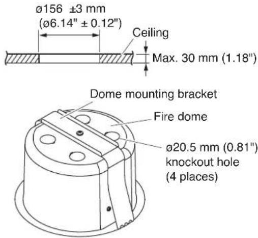
Step 2. Punch out the knockout hole in the fire dome, then install the supplied cable entry rubber grommet in the knockout hole.
Note: The grommet's cable entry hole is covered with a thin membrane. Cut a hole in the membrane to match the size of the speaker cable used.
Step 3. Loosen the wing nut.
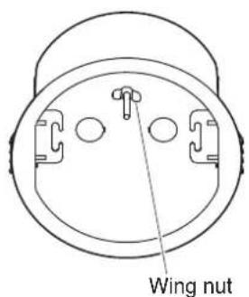
![[Cross-Section View] [Interior View] Dome mounting bracket Fire dome Important Unscrew the wing nut until it reaches the end of the screw shaft.](/content/2026/05/979504/images/76a36351c592e788391c1c6aad8e9e0062726171a4e97bf8f9c87848634ba610.jpg)
Step 4. Feed the speaker cable through the rubber grommet into the dome interior.
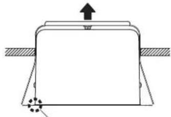
Step 5. Press the fire dome assembly into the previously prepared hole in the ceiling.
natural_image
Simple line drawing of a mechanical component with an upward arrow and force indicators (no text or symbols)Each leg should settle on the collar.
Push up the dome assembly.

Caution
Since the dome mounting bracket is not placed on the ceiling panel at this stage, as shown in the above figure, the dome could fall if released, so continue to provide manual support.
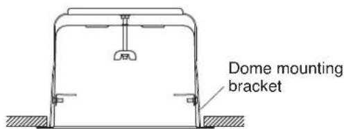
Step 6. Push in the dome mounting wing nut.
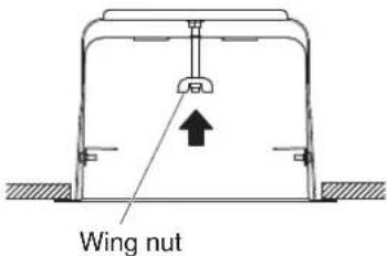
Firmly push the wing nut and screw shaft in the direction indicated by the arrow.

natural_image
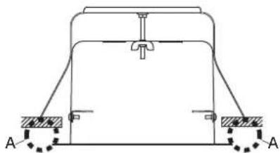
Pure mechanical diagram showing a frame structure with supports and a central component, no text or symbols present.The legs of the dome mounting bracket will pop open and settle on the back surface of the ceiling panel, providing the dome with partial support. If released, a gap behind the collar of the dome will result (A).
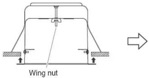
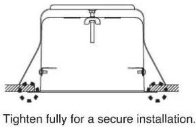
Step 7. Turn the dome mounting wing nut clockwise to tighten and firmly secure the dome to the ceiling panel.
Step 8. Make wiring.
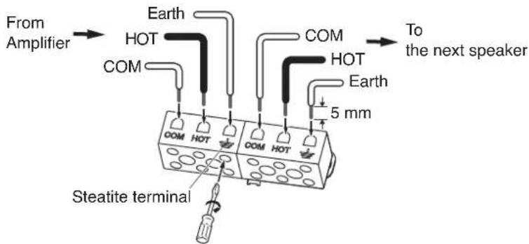
8-1. Insert the lead-in cables (cables from the amplifier) and lead-out cables (cables to other speakers) into the input connector according to the terminal indication.
Note: Hook the two ends of one of the speaker mounting springs into the hooks in the fire dome during connection.
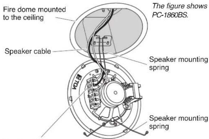
Terminal block
- PC-1860F: Push-in type input terminal
• PC-1860BS: Steatite terminal
- PC-1860BS-C: Steatite terminal
[PC-1860F terminal block]
When making a bridge connection:
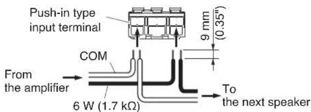
Wiring diagram
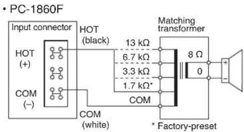
• PC-1860BS
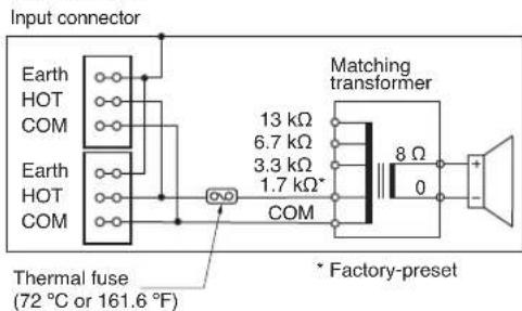
- PC-1860BS-C

[PC-1860BS/1860BS-C terminal block]
When making a bridge connection:
8-2. Change the input impedance as needed.
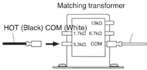
The speaker's input is factory-preset to 1.7k . When changing the input impedance, detach the blank wire connected to the matching transformer, and reinsert it into the desired input tap referring to the table below.
| Impedance 1 | .7 kΩ 3.3 | kΩ 6.7 | kΩ 13 kΩ | |
| 100 V line | 6 W | 3 W | 1.5 W | 0.8 W |
| 70 V line | 3 W | 1.5 W | 0.8 W | 0.4 W |
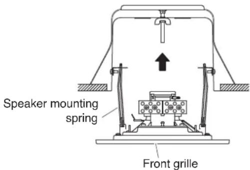
Step 9. Hook the remaining speaker mounting spring into its corresponding hook in the dome, then push the speaker up into the fire dome.
Caution
Do not press directly on the front grille, as the grille could become dented or damaged.
Note
See to it that the speaker cable is not pinched between the fire dome and the front grille.
4. INSTALLING THE SAFETY WIRE (prepared separately by the installer)
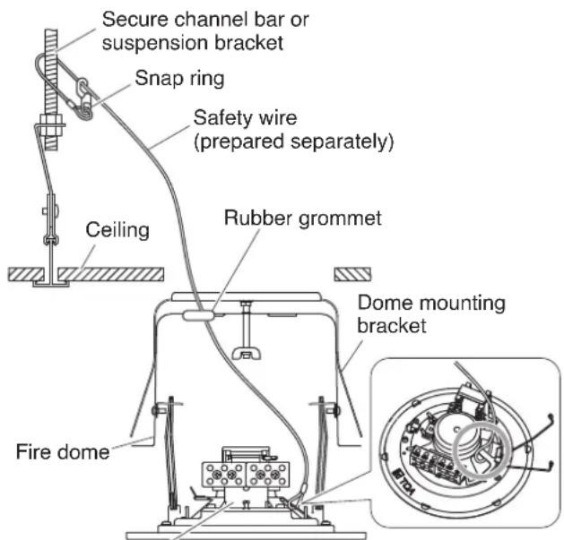
Step 1. Tie one end of the safety wire around the speaker frame.
Note: When using a bare safety wire, wrap insulation tape around it to prevent electrical contact with the connection terminals, transformer taps, or other electric parts.
Step 2. Make a cut in the rubber grommet with a knife or a screwdriver, then run the safety wire through it.
Step 3. Tie snap ring around a secure channel bar or suspension bracket.
Step 4. Feed the speaker cable through the rubber grommet into the dome interior.
Step 5. Secure the fire dome assembly in the ceiling, then connect the speaker cable to the terminal block.
Step 6. Attach the speaker to the fire dome.
Speaker frame
Note: If the speaker cable and safety wire are too long, to prevent them from being tangled inside the fire dome, gently push them back out of the fire dome so the rubber grommet does not get removed.
5. SPECIFICATIONS
5.1. PC-1860F
| Rated Input 6 W (100 V line), 3 W (70 V line) | |
| Rated Impedance 100 V line: | .7 kΩ (6 W), 3.3 kΩ (3 W), 6.7 kΩ (1.5 W), 13 kΩ (0.8 W) |
| 70 V line: 1.7 kΩ (3 W), 3.3 kΩ (1.5 W), 6.7 kΩ (0.8 W), 13 kΩ (0.4 W) | |
| Sensitivity 95 dB (1 W, 1 m) (500 Hz – 5 kHz, pink noise) | |
| Frequency Response 170 Hz – 20 kHz (peak –20 dB) | |
| Speaker Component 12 cm (5") cone-type | |
| Dimensions for Fixing Hole | Mounting hole: ø156±3 mm (ø6.14"±0.12"), Ceiling thickness: 5 – 25 mm (ø0.2" – 0.98") |
| Speaker Mounting Method | Spring catch |
| Operating Temperature | -10 to +50 °C (14 to 122 °F) |
| Applicable Cable | Solid wire: 0.5 – 3 mm2 (AWG 20 – 12) |
| Connection | Push wire connection (Bridging terminal-2 branch type) |
| Finish | Frame: Steel plate, white (RAL 9016 equivalent), paintGrille: Steel net, white (RAL 9016 equivalent), paintFire dome: Steel plate, black, paint |
| Dimensions | ø180 x 5 (exposed section) + 100 (d) mm (ø7.09" x 0.2" + 3.94") |
| Weight | 1 kg (2.2 lb) |
| Accessories | Rubber grommet ...... 2, Paper pattern ...... 1 |
Note: The design and specifications are subject to change without notice for improvement.
5.2. PC-1860BS, PC-1860BS-C
| Model No. | PC-1860BS | PC-1860BS-C |
| Standards | Certified to the European Standard EN 54-24: 2008Loudspeaker for voice alarm systems for fire detection and fire alarm systemsCE1438 | |
| In compliance with the British Standard BS-5839-8: 2008 | ||
| Rated Input | 6 W (100 V line), 3 W (70 V line) | |
| Rated Impedance | 100 V line: 1.7 kΩ (6 W), 3.3 kΩ (3 W), 6.7 kΩ (1.5 W), 13 kΩ (0.8 W)70 V line: 1.7 kΩ (3 W), 3.3 kΩ (1.5 W), 6.7 kΩ (0.8 W), 13 kΩ (0.4 W) | |
| Sensitivity | 95 dB (1 W, 1 m) (500 Hz – 5 kHz, pink noise)93 dB (1 W, 1 m) (100 Hz – 10 kHz, pink noise)81 dB (1 W, 4 m) (100 Hz – 10 kHz, pink noise) | 94 dB (1 W, 1 m) (500 Hz – 5 kHz, pink noise)92 dB (1 W, 1 m) (100 Hz – 10 kHz, pink noise)80 dB (1 W, 4 m) (100 Hz – 10 kHz, pink noise) |
| Maximum Sound Pressure Level | 100 dB (6 W, 1 m)(100 Hz – 10 kHz, pink noise)88 dB (6 W, 4 m) (100 Hz – 10 kHz, pink noise) | 99 dB (6 W, 1 m) (100 Hz – 10 kHz, pink noise)87 dB (6 W, 4 m) (100 Hz – 10 kHz, pink noise) |
| Frequency Response | 170 Hz – 20 kHz (peak –20 dB) | |
| Coverage Angle (-6 dB) Horizontal and Vertical:165° (500 Hz), 175° (1 kHz), 165° (2 kHz), 70° (4 kHz) according to EN 54-24 | ||
| Environmental type | A (indoor applications) | |
| Speaker Component | 12 cm (5") cone-type | |
| Operating Temperature | -10 to +50 °C (14 to 122 °F) | |
| Dimensions for Fixing Hole | Mounting hole: ø156 ±3 mm (ø6.14" ±0.12"), Ceiling thickness: 5 – 25 mm (0.2" – 0.98") | |
| Speaker Mounting Method | Spring catch | |
| Applicable Cable | Solid wire: 0.8 – 6 mm2 (AWG 18 – 10) | |
| Connection | 2-Steatite connector (3 pole) | |
| DC Blocking Capacitor | —— | 1.0 μF |
| Finish | Frame: Steel plate,white (RAL 9016 equivalent),paintGrille: Steel net, white (RAL 9016 equivalent), paintFire dome: Steel plate, black, paint | |
| Dimensions | ø180 x 5 (exposed section) + 100 (d) mm (ø7.09" x 0.2" + 3.94") | |
| Weight | 1.1 kg (2.43 lb) | |
| Accessories | Rubber grommet ...... 2, Paper pattern ...... 1 | |
Notes: • The design and specifications are subject to change without notice for improvement.
- The Specifications data was measured in an anechoic chamber.
- Reference axis: Axis is on the center of grill surface and perpendicular to the grill surface.
- Reference plane: Plane is on the grill surface and perpendicular to the reference axis.
• Horizontal plane: Plane is containing the reference axis and perpendicular to the reference plane.
- Other technical data: See the specification sheet PC-1860BS/PC-1860BS-C.
عند تركيب الوحدة
- CEILING MOUNT FIRE DOME SPEAKER PC-1860F, PC-1860BS, PC-1860BS-C
- SAFETY PRECAUTIONS
- WARNING
- CAUTION
- GENERAL DESCRIPTION
- Traceability Information for Europe
- INSTALLATION
- Step 8. Make wiring.
- 8-2. Change the input impedance as needed.
- Note
- INSTALLING THE SAFETY WIRE (prepared separately by the installer)
- SPECIFICATIONS
- PC-1860F
- PC-1860BS, PC-1860BS-C
- عند تركيب الوحدة
Brand : TOA
Model : PC-1860
Category : Loudspeaker