
MaxiSYS MS908S II - Car diagnostics Autel - Free user manual and instructions
Find the device manual for free MaxiSYS MS908S II Autel in PDF.


| Product Type | Automotive Diagnostic Tool |
| Brand | Autel |
| Model | MaxiSYS MS908S II |
| Dimensions (Tablet) | 300 mm x 220 mm x 50 mm (11.81" x 8.66" x 1.97") |
| Weight (Tablet) | Net: 1.42 kg (3.13 lb); Gross: 8.655 kg (19.08 lb) |
| Operating System | Android™ 10 |
| Processor | Qualcomm octa-core (2.2 GHz quad-core A73 + 1.8 GHz quad-core A53) |
| Memory | 4 GB RAM & 128 GB onboard memory |
| Display | 9.7-inch LCD capacitive touchscreen, 2048 x 1536 resolution |
| Connectivity | Wi-Fi 802.11 a/b/g/n/ac, Bluetooth v5.0 + EDR, USB 2.0, HDMI, SD card (up to 64 GB) |
| Battery | 11000 mAh 3.7 V Lithium-polymer, up to 7.5 hours continuous operation |
| Input Voltage (Tablet) | 12 V DC (9–24 V) |
| Power Consumption (Tablet) | 6.5 W |
| Operating Temperature | 0 to 50 °C (32 to 122 °F) |
| Storage Temperature | -20 to 60 °C (-4 to 140 °F) |
| Diagnostic Protocols | ISO 9142-2, ISO 14230-2, ISO 15765-4, K/L-Line, SAE-J1850, CAN, J1939, J1708, etc. |
| Service Functions | Oil Reset, EPB, TPMS, BMS, SAS, DPF, Immobilizer and more |
| VCI Connectivity | Bluetooth v2.1 + EDR and USB 2.0; range ~210 ft (70 m) |
| Main Cable Length | 1.5 m (4.9 ft) |
| Included Accessories | Main cable, AC/DC power adapter, auxiliary power outlet adapter, spare fuses (x2), clamp cable, USB to Ethernet adapter |
| Safety Compliance | FCC, CE, RoHS |
| Maintenance | Clean with soft cloth and mild detergent; keep dry; do not disassemble |
| Reparability | Battery factory replaceable only; repair service available via Autel authorized centers |
Frequently Asked Questions - MaxiSYS MS908S II Autel
User questions about MaxiSYS MS908S II Autel
0 question about this device. Answer the ones you know or ask your own.
Ask a new question about this device
Download the instructions for your Car diagnostics in PDF format for free! Find your manual MaxiSYS MS908S II - Autel and take your electronic device back in hand. On this page are published all the documents necessary for the use of your device. MaxiSYS MS908S II by Autel.
USER MANUAL MaxiSYS MS908S II Autel
Autel ^® , MaxiSys ^® , MaxiDAS ^® , MaxiScan ^® , MaxiTPMS ^® , MaxiRecorder ^® , and MaxiCheck ^® are trademarks of Autel Intelligent Technology Corp., Ltd., registered in China, the United States, and other countries. All other marks are trademarks or registered trademarks of their respective holders.
Copyright Information
No part of this manual may be reproduced, stored in a retrieval system or transmitted in any form or by any means electronic, mechanical, photocopying, recording, or otherwise without the prior written permission of Autel.
Disclaimer of Warranties and Limitation of Liabilities
All information, specifications and illustrations in this manual are based on the latest information available at the time of printing.
Autel reserves the right to make changes at any time without notice. While information of this manual has been carefully checked for accuracy, no guarantee is given for the completeness and correctness of the contents, including but not limited to the product specifications, functions, and illustrations.
Autel will not be liable for any direct, special, incidental, or indirect damages, or for any economic consequential damages (including lost profits) as a result of using this product.
IMPORTANT
Before operating or maintaining this unit, please read this manual carefully, paying extra attention to the safety warnings and precautions.
For Services and Support:

pro.autel.com
www.autel.com

1-855-288-3587/1-855-AUTELUS (North America)
0086-755-86147779 (China)

support@autel.com
For details, please refer to the Service Procedures in this manual.
Safety Information
For your own safety and the safety of others, and to prevent damage to the device and vehicles upon which it is used, it is important that the safety instructions presented throughout this manual be read and understood by all persons operating or coming into contact with the device.
There are numerous procedures, techniques, tools, and parts required for servicing vehicles, as well as the skills of the person doing the work. Because of the vast number of test applications and variations in the products that can be tested with this equipment, we cannot possibly anticipate or provide advice or safety messages to cover every circumstance. It is the automotive technician's responsibility to be knowledgeable of the system being tested. It is crucial to use proper service methods and test procedures. It is essential to perform tests in an appropriate and acceptable manner that does not endanger your safety, the safety of others in the work area, the device being used, or the vehicle being tested.
Before using the device, always refer to and follow the safety messages and applicable test procedures provided by the manufacturer of the vehicle or equipment being tested. Use the device only as described in this manual. Be sure to read, understand, and follow all safety messages and instructions in this manual.
Safety Messages
Safety messages are provided to help prevent personal injury and equipment damage. All safety messages are introduced by a signal word indicating the hazard level.

DANGER
Indicates an imminently hazardous situation which, if not avoided, will result in death or serious injury to the operator or to bystanders.

WARNING
Indicates a potentially hazardous situation which, if not avoided, could result in death or serious injury to the operator or to bystanders.
Safety Instructions
The safety messages herein cover situations Autel is aware of at the time of publication. Autel cannot know, evaluate or advise you as to all of the possible hazards. You must be certain that any condition or service procedure encountered does not jeopardize your personal safety.

DANGER
When an engine is operating, keep the service area WELL VENTILATED or attach a building exhaust removal system to the engine exhaust system. Engines produce carbon monoxide, an odorless, poisonous gas that causes slower reaction time and can lead to serious personal injury or loss of life.

Do Not Turn the Volume Up Too Loud When Using Headphones
Listening at high volumes that over-stimulate the ear for long periods of time may result in loss of hearing.

SAFETY WARNINGS:
● Always perform automotive testing in a safe environment.
- Wear safety eye protection that meets ANSI standards.
- Keep clothing, hair, hands, tools, test equipment, etc., away from all moving or hot engine parts.
- Operate the vehicle in a well-ventilated work area.
- Put the transmission in PARK (for automatic transmission) or NEUTRAL (for manual transmission) and make sure the parking brake is engaged.
- Put blocks in front of the drive wheels and never leave the vehicle unattended while testing.
- Be extra cautious when working around the ignition coil, distributor cap, ignition wires and spark plugs. These components create hazardous voltages when the engine is running.
- Keep a fire extinguisher suitable for gasoline, chemical, and electrical fires nearby.
- Do not connect or disconnect any test equipment while the ignition is on or the engine is running.
- Keep the test equipment dry, clean, and free from oil, water, and grease. Use a mild detergent on a clean cloth to clean the outside of the equipment as necessary.
- Do not drive the vehicle and operate the test equipment at the same time. Any distraction may cause an accident.
- Refer to the service manual for the vehicle being serviced and adhere to all diagnostic procedures and precautions. Failure to do so may result in personal injury or damage to the test equipment.
- To avoid damaging the test equipment or generating false data, make sure the vehicle battery is fully charged and the connection to the vehicle DLC is clean and secure.
- Do not place the test equipment on the distributor of the vehicle. Strong electromagnetic interference can damage the equipment.
CONTENTS
SAFETY INFORMATION......II
SAFETY INSTRUCTIONS......II
1 USING THIS MANUAL ....1
CONVENTIONS....1
2 GENERAL INTRODUCTION ....3
MAXISYS TABLET 3
VCI — WIRELESS DIAGNOSTIC INTERFACE....7
ACCESSORIES KIT 8
3 GETTING STARTED....11
POWER UP 11
POWER DOWN....14
4 DIAGNOSTICS....16
ESTABLISH VEHICLE COMMUNICATION 16
GETTING STARTED 20
VEHICLE IDENTIFICATION....21
NAVIGATION 26
MAIN MENU 30
DIAGNOSIS....30
GENERIC OBDII OPERATIONS ....44
EXIT DIAGNOSTICS 48
5 SERVICE....50
OIL RESET SERVICE ....50
ELECTRIC PARKING BRAKE (EPB) SERVICE 51
TIRE PRESSURE MONITORING SYSTEM (TPMS) SERVICE ....51
BATTERY MANAGEMENT SYSTEM (BMS) SERVICE....52
STEERING ANGLE SENSOR (SAS) SERVICE ....52
DIESEL PARTICLE FILTER (DPF) SERVICE....53
IMMOBILIZER (IMMO) SERVICE 54
6 ADAS....55
7 DATA MANAGER....56
VEHICLE HISTORY....57
WORKSHOP INFORMATION ....59
CUSTOMER 59
IMAGE 60
PDF FILES....62
REVIEW DATA 62
UNINSTALL APPS 63
DATA LOGGING....63
8 SETTINGS....64
OPERATIONS....64
9 UPDATE....68
10 VCI MANAGER....70
VCI CONNECTION VIA BLUETOOTH ....70
BAS CONNECTION VIA BLUETOOTH....72
VCI UPDATE 72
BAS UPDATE....73
11 REMOTE DESKTOP 75
OPERATIONS....75
12 SUPPORT 77
PRODUCT REGISTRATION ....77
SUPPORT SCREEN LAYOUT....77
13 BATTERY TEST 81
MAXIBAS BT506 TESTER....81
TEST PREPARATION 83
IN-VEHICLE TEST 84
OUT-VEHICLE TEST....90
14 MAXIVIEWER....92
15 QUICK LINK 94
16 USER FEEDBACK 95
17 MAXISCOPE 96
18 MAXIVIDEO....97
ADDITIONAL ACCESSORIES 98
OPERATIONS....101
19 MAINTENANCE AND SERVICE 103
MAINTENANCE INSTRUCTIONS....103
TROUBLESHOOTING CHECKLIST 103
ABOUT BATTERY USAGE 104
SERVICE PROCEDURES 105
20 COMPLIANCE INFORMATION....108
21 WARRANTY....110
12-MONTH LIMITED WARRANTY 110
1 Using This Manual
This manual contains device usage instructions.
Some illustrations shown in this manual may make reference to modules and optional equipment that are not included in your system.
Conventions
The following conventions are used:
Bold Text
Bold text is used to highlight selectable items such as buttons and menu options.
Example:
- Tap OK.
Notes and Important Messages
Notes
A NOTE provides helpful information such as additional explanations, tips, and comments.
Example:
NOTE
New batteries reach full capacity after approximately 3 to 5 charging and discharging cycles.
Important
IMPORTANT indicates a situation which, if not avoided, may result in damage to the tablet or vehicle.
Example:
IMPORTANT
Keep the cable away from heat, oil, sharp edges and moving parts. Replace damaged cables immediately.
Hyperlink
Hyperlinks are available in electronic documents. Blue italic text indicates a selectable hyperlink and blue underlined text indicates a website link or an email address link.
Illustrations
Illustrations used in this manual are samples, and the actual testing screen may vary for each vehicle being tested. Observe the menu titles and on-screen instructions to make correct option selection.
Procedures
An arrow icon indicates a procedure.
Example:
To use the camera:
- Tap the Camera icon. The camera screen opens.
- Focus the image to be captured in the viewfinder.
- Tap the inner blue circle. The viewfinder now shows the captured picture and auto-saves the taken photo.
- Tap the thumbnail image on the top-right corner of the screen to view the stored image.
- Tap the Back or Home button to exit the camera application.
2 General Introduction
The MaxiSys® MS908S II Diagnostics Platform is an evolutionary smart solution for specialized automotive diagnostics. Utilizing the powerful octa-core processor (Qualcomm Kryo 260 CPU), and a 9.7-inch LED capacitive touchscreen, combined with the best possible coverage of OE-level diagnostics, and based on the revolutionary multitask-capable Android 10 Operating system, the MaxiSys organizes information with test instrumentation to help you diagnose symptoms, codes, and customer complaints easily, quickly and efficiently.
There are two main components to the MaxiSys system:
● MaxiSys Tablet — the central processor and monitor for the system.
● Vehicle Communication Interface (VCI) — the device for accessing vehicle data.
This manual describes the construction and operation of these devices and how they work together to deliver diagnostic solutions.
MaxiSys Tablet
Function Descriptions

Figure 2-1 MaxiSys Tablet, Front View
① 9.7" LED Capacitive Touchscreen
② Ambient Light Sensor — detects ambient light brightness
3 Microphone

Figure 2-2 MaxiSys Tablet, Back View
① Audio Speaker
② Collapsible Stand — extends from the back to allow hands-free viewing of the tablet
③ Camera Lens
4 Camera Flash

Figure 2-3 MaxiSys Tablet, Left Side
① Mini SD (Secure Digital) Card Slot
2 Mini USB (Universal Serial Bus) Port (it cannot be used at the same time with the No. 4 USB Port in Figure 2-4 MaxiSys Tablet, Top View)
3 Headphone Jack
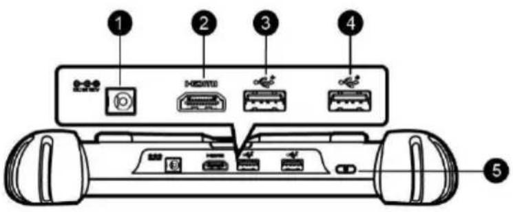
Figure 2-4 MaxiSys Tablet, Top View
① DC Power Supply Input Port
② HDMI (High-definition Multimedia Interface) Port
③ USB Port
4 USB Port (it cannot be used at the same time with the Mini USB Port in Figure 2-3 MaxiSys Tablet, Left Side)
5 Lock/Power Button — long press to turn the tablet on and off, or short press to lock the screen
Power Sources
The tablet can receive power from any of the following sources:
- Internal battery pack
- AC/DC power supply
- Vehicle power
IMPORTANT
Please charge the battery with the ambient temperature between 0^ C and 45^ C. If charge the battery when the temperature is out of range, the battery may catch on fire.
Internal Battery Pack
The tablet can be powered with its internal rechargeable battery pack, which if fully charged can provide sufficient power for about 7.5 hours of continuous operation.
AC/DC Power Supply
The tablet can be powered from a wall socket using the AC/DC power adapter. The AC/DC power supply also charges the internal battery pack.
Vehicle Power
The tablet can be powered from the auxiliary power outlet adapter or other suitable power port on the test vehicle through a direct cable connection. The vehicle power cable connects to the DC power supply port on the top side of the tablet.
Technical Specifications
Table 2-1 Tablet Specifications
| Item | Description |
| Operating System | Android^TM 10 |
| Processor | Qualcomm octa-core processor (2.2 GHz quad-core A73 + 1.8 GHz quad-core A53) |
| Memory | 4 GB RAM & 128 GB On-board memory |
| Display | 9.7-inch LCD capacitive touchscreen with 2048 x 1536 resolution |
| Connectivity | Wi-Fi (802.11 a/b/g/n/ac)USB 2.0Bluetooth v5.0 + EDRSD card (support up to 64 GB)HDMI |
| Camera (Rear) | 16.0 megapixel, auto focus with flashlight |
| Sensors | Gravity accelerometer, ambient light sensor (ALS) |
| Audio Input/Output | MicrophoneDual speakers3-band 3.5 mm stereo/standard headset jack |
| Power and Battery | 11000 mAh 3.7 V Lithium-polymer batteryCharging via 12 V AC/DC power supply with a temperature between 0 °C and 45 °C |
| Input Voltage | 12 V (9–24 V) |
| Power Consumption | 6.5 W |
| Operating Temp. | 0 to 50 °C (32 to 122 °F) |
| Storage Temp. | -20 to 60 °C (-4 to 140 °F) |
| Dimensions (WxHxD) | 300 mm (11.81") x 220 mm (8.66") x 50 mm (1.97") |
| Weight | ● NW: 1.42 kg (3.13 lb.)● GW: 8.655 kg (19.08 lb.) |
| Protocols | ISO 9142-2, ISO 14230-2, ISO 15765-4, K/L-Line, Flashing Code, SAE-J1850 VPW, SAE-J1850 PWM, CAN ISO 11898, Highspeed, Middlespeed, Lowspeed and Singlewire CAN, GM UART, UART Echo Byte Protocol, Honda Diag-H Protocol, TP 2.0, TP 1.6, SAE J1939, SAE J1708, Fault-Tolerant CAN |
VCI — Wireless Diagnostic Interface
Function Descriptions
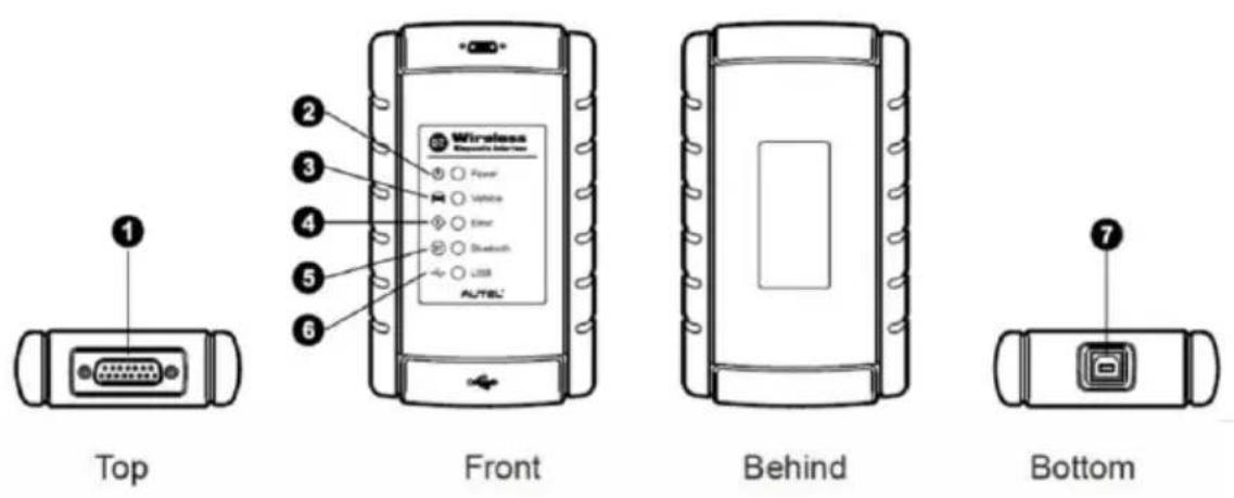
Figure 2-5 Wireless Diagnostic Interface
① Vehicle Data Connector (DB15-pin)
② Power LED — lights solid green when the device is powered on
③ Vehicle LED — blinks green when the device is communicating with the vehicle's network
4 Error LED — lights solid red when serious hardware failure occurs; also blinks red when the device is updating software/firmware
5 Bluetooth LED — lights solid green when the device is connected with the tablet through Bluetooth communication
6 USB LED — lights solid green when the device is properly connected and communicating with the tablet via the USB cable
⑦ USB Port
Communication
The Wireless Diagnostic Interface supports both Bluetooth and USB communication. It can transmit vehicle data to the tablet with or without a physical connection. The working range of the transmitter through Bluetooth communication is about 210 feet (about 70 m). A signal lost due to moving out of range automatically restores itself when the tablet is brought closer to the VCI.
Power Sources
The Wireless Diagnostic Interface operates on 12-volt vehicle power, which it receives through the vehicle data connection port. The device powers on whenever it is connected to an OBDII/EOBD compliant Data Link Connector (DLC).
Technical Specifications
Table 2-2 Wireless Diagnostic Interface Specifications
| Item | Description |
| Communications | Bluetooth v2.1 + EDR; USB 2.0 |
| Wireless Frequency | 2.4 GHz |
| Input Voltage Range | 12 V DC |
| Supply Current | 200 mA @ 12 V DC |
| Operating Temp. | 0 °C to 50 °C (ambient) |
| Storage Temp. | -20 °C to 70 °C (ambient) |
| Dimensions (LxWxH) | 147.5 mm (5.80") x 85.5 mm (3.37") x 29.0 mm (1.14") |
| Weight | 215 g (0.473 lb.) |
Accessories Kit
Main Cable
The VCI can be powered through the Main Cable when connected to an OBDII/EOBD compliant vehicle. The Main Cable connects the VCI to the vehicle's Data Link Connector (DLC), through which the VCI can transmit vehicle data to the tablet.
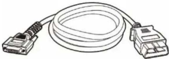
natural_image
Line drawing of a broadband cable with two connectors (no text or symbols)Figure 2-6 Main Cable — 1.5 m in length
OBDI Adapters (Optional)
The optional OBDI adapters are for Non-OBDII vehicles. The adapter used depends on the type of vehicle being tested. The most common adapters are shown.

Benz-14

Chrysler-16

BMW-20
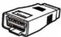
Nissan-14

Kia-20

Fiat-3

PSA-2

Mazda-17

Volkswagen/
Audi-2+2

Benz-38

Mitsubishi/
Hyundai-12+16
Other Accessories


Standard 2.0 USB Cable
Connects the tablet to the VCI.
Mini USB Cable
Connects the tablet to the Windows-based PC.

natural_image
Simple line drawing of a rectangular device with coiled wires attached (no text or symbols)AC/DC External Power Adapter
Connects the tablet to the external DC power port for power supply.

Auxiliary Power Outlet Adapter
Supplies power to the tablet or the VCI through connection to the vehicle's auxiliary power outlet, as some non-OBDII vehicles cannot provide power via the DLC connection.

Spare Fuse x2
A safety device for the auxiliary power outlet adapter.

Clamp Cable
Provides power to the tablet or the VCI through connection to the vehicle battery.

USB to Ethernet Adapter
Network connection function can be realized through this device.
3 Getting Started
Make sure the tablet has sufficient power or is connected to an external power supply (see Power Sources on page 5).
Power Up
Long press the Lock/Power button on the top right side of the tablet to switch the unit on. The power LED will illuminate green. The system boots up and displays the lock screen. Press and drag the inner ring to the edge of the circle to unlock the screen; the MaxiSys Job Menu displays.

Figure 3-1 Sample MaxiSys Job Menu
① Application Buttons
② Locator and Navigation Buttons
③ Status Icons

NOTE
The screen is locked by default upon startup. We recommend that you lock the screen when not in use to protect private information in the system and conserve power.
Almost all operations on the tablet are controlled through the touch screen. The touch screen navigation is menu-driven, which allows you to quickly locate the test procedure or data that you need through a series of choices and questions. Detailed descriptions of the menu items are found in the chapters for each application.
Application Buttons
The table below briefly describes each of the applications in the MaxiSys system.
Table 3-1 Applications
| Name | Button | Description |
| Diagnostics |  | Accesses the unit's diagnostics functions. See Diagnostics on page 16. |
| Service |  | Accesses special functions menu. See Service on page 50 for details. |
| ADAS |  | Accesses ADAS systems menu. See ADAS on page 55. |
| Data Manager |  | Accesses the saved repair shop, customer and vehicle data including detailed vehicle diagnostics and test records. See Data Manager on page 56. |
| Settings |  | Accesses the system settings menu and general tablet menu. See Settings on page 64. |
| Update |  | Accesses system software update menu. See Update on page 68. |
| VCI Manager |  | Accesses VCI connection menu. See VCI Manager on page 70. |
| Remote Desktop |  | Configures your unit to receive remote support using the TeamViewer application. See Remote Desktop on page 75. |
| Support |  | Launches the Support platform that synchronizes Autel's online service base station with the MaxiSys tablet. See Support on page 77. |
| Battery Test |  | Accesses the Battery Test menu with two functions, including in-vehicle test and out-vehicle test. See Battery Test on page 81. |
| MaxiViewer |  | Provides a quick search for supported functions and/or vehicles. See MaxiViewer on page 92. |
| Quick Link |  | Provides associated website bookmarks to allow quick access to product update, service, support and other information. See Quick Link on page 94. |
| User Feedback |  | Allows you to submit questions related to this product. See User Feedback on page 95. |
| MaxiScope |  | Configures the unit to operate as an automotive oscilloscope to perform electrical and electronic circuit tests and monitor signal activities. See MaxiScope on page 96. |
| MaxiVideo |  | Configures the unit to operate as a video scope device by connecting to an Imager head cable for close vehicle inspections. See MaxiVideo on page 97. |
Page Control and Navigation Buttons
Operations of the page control and navigation buttons are described as below:
Table 3-2 Page Control and Navigation Buttons
| Name | Button | Description |
| Page Control |  | Indicates the location of the current screen. Swipe screen left or right to view previous or next screen. |
| Back |  | Returns to the previous screen. |
| MaxiSys Home |  | Returns to the MaxiSys Job Menu. |
| Android Home |  | Returns to the Android system Home screen. |
| Recent Apps |  | Displays a list of currently running applications. Tap an app icon to launch. To remove an app, swipe it to the right. |
| Browser |  | Launches the Google Chrome browser. |
| Camera |  | Tap to launch camera. Press and hold to capture a screenshot of the display screen. Saved files are stored in the Data Manager application for later review. See Data Manager on page 56. |
| Display & Sound |  | Allows you to adjust the brightness of the screen and the volume of the audio output. |
| VCI |  | Opens the VCI Manager application. A green BT or USB cable icon at the bottom-right corner indicates the VCI device is connected via Bluetooth or USB cable, while a red “x” indicates no connection. |
| MaxiSys Shortcut |  | Returns to the Diagnostics screen. |
| Service |  | Returns to the Service screen. |
To use the camera:
- Tap the Camera icon. The camera screen opens.
- Focus the image to be captured in the viewfinder.
- Tap the inner blue circle. The viewfinder now shows the captured picture and auto-saves the taken photo.
- Tap the thumbnail image on the top right corner of the screen to view the stored image.
- Tap the Back or Home button to exit the camera application.
System Status Icons
These icons are the standard status icons of the Android operating system. Your MaxiSys tablet is a fully functional Android Pad.
Power Down
All vehicle communications must be terminated before shutting down the tablet. A warning message appears if a shutdown is attempted while the tablet is communicating with the vehicle. Forcing a shut down while the tablet is communicating may lead to ECU (Electronic Control Unit) problems on some vehicles. Please fully exit the Diagnostics application before shutting off the tablet.
To power down the MaxiSys tablet:
- Long press the Lock/Power Button.
- Tap Power Off.
- Tap OK.
Reboot System
In case of a system crash, long press the Lock/Power button and tap Reboot to restart the system.
4 Diagnostics
The Diagnostics application can access the electronic control unit of various vehicle control systems, such as engine, transmission, antilock brake system (ABS), airbag system (SRS) and more.
Establish Vehicle Communication
The Diagnostics operations require connecting the MaxiSys MS908S II Diagnostics Platform to the test vehicle through the VCI using the main cable and test adapters (for non-OBDII vehicles). To establish proper vehicle communication to the tablet, you need to perform the following steps:
- Connect the VCI to the vehicle's DLC for both communication and power source.
- Connect the VCI to the tablet via Bluetooth pairing, or USB connection.
- When the above steps are completed, check the VCI navigation button at the bottom bar on the screen, if a green badge displays at the lower right corner, the MaxiSys MS908S II Diagnostics Platform is ready to start vehicle diagnosis.
Vehicle Connection
The method used to connect the VCI to a vehicle's DLC depends on the vehicle's configuration as follows:
● A vehicle equipped with an On-board Diagnostics Two (OBDII) management system supplies both communication and 12-volt power through a standardized J-1962 DLC.
- A vehicle not equipped with an OBDII management system supplies communication through a DLC connection, and in some cases supplies 12-volt power through the auxiliary power outlet or a connection to the vehicle battery.
OBDII Vehicle Connection
This type of connection only requires the main cable without any additional adapter.
To connect to an OBDII vehicle
- Connect the main cable's female adapter to the Vehicle Data Connector on the VCI, and tighten the captive screws.
- Connect the cable's male adapter to the vehicle's DLC, which is generally located under the vehicle dashboard.

NOTE
The vehicle's DLC is not always located under the dashboard. Refer to the user manual of the test vehicle for additional connection information.
Non-OBDII Vehicle Connection
This type of connection requires both the main cable and a required OBDI adapter for the specific vehicle being serviced.
There are three possible scenarios for Non-OBDII vehicle connection:
● DLC connection supplies both communication and power.
- DLC connection supplies communication and power is to be supplied via the vehicle's auxiliary power outlet.
- DLC connection supplies communication and power is to be supplied via connection to the vehicle battery.
To connect to a Non-OBDII Vehicle
- Connect the main cable's female adapter to the Vehicle Data Connector on the VCI, and tighten the captive screws.
- Locate the required OBDI adapter and connect its jack to the main cable's male adapter.
- Connect the attached OBDI adapter to the vehicle's DLC.

NOTE
Some vehicles may have more than one adapters or may have test leads instead of an adapter. Whatever the case, make the proper connection to the vehicle's DLC as required.
To connect the auxiliary power outlet adapter
- Plug the DC power connector of the auxiliary power outlet adapter into the DC power supply input port on the device.
- Connect the male connector of the auxiliary power outlet adapter to the vehicle's auxiliary power outlet.

NOTE
After the VCI is successfully connected to the vehicle, the Power LED on the device illuminates, and a brief beeping sound will be heard.
VCI Connection
After the VCI is properly connected to the vehicle, the Power LED on the VCI illuminates solid green, and is ready to establish communication with the tablet.
The Wireless Diagnostic Interface supports 2 communication methods with the tablet: Bluetooth and USB.
Bluetooth Connection
Among all methods, Bluetooth (BT) pairing is recommended as the first choice for the communication between the tablet and the VCI. The working range for Bluetooth communication is about 210 feet (70 m); this means you can perform vehicle diagnosis freely around the workshop with greater convenience.
To expedite multi-vehicle diagnostics, more than one VCI can be used in busy repair shops enabling technicians to quickly pair (via Bluetooth) their diagnostic tablets to each VCI separately and therefore eliminating the need to physically connect the VCI to each vehicle.
To pair up the tablet with the VCI via Bluetooth
- Power up the tablet.
- Select the VCI Manager application from the MaxiSys Job Menu.
- When the VCI Manager application is opened, the device automatically starts scanning for available VCIs around for Bluetooth pairing. Available VCIs are listed in the Settings section on the right side of the screen.

NOTE
If no VCI is found, this may indicate that the signal strength of the transmitter is too weak to be detected. In this case try to get closer to the device, or reposition the VCI, and remove all possible objects that may cause signal interference. When done, tap the Scan button at the top-right corner to start searching again.
- The VCI name appears as "Maxi" suffixed with the device serial number. Select the required device for pairing. (If more than one VCIs is used in the shop, ensure the correct VCI is selected to pair.)
- When pairing is successfully done, the connection status displayed to the right of the device name reads "Connected."
- Wait for a few seconds, and the VCI button on the system navigation bar on the bottom of the screen shall appear as a green circle badge, indicating the tablet is connected to the VCI, and is ready to perform vehicle diagnosis.
Refer to VCI Connection via Bluetooth on page 70 for additional information.
USB Cable Connection
The USB cable connection is a simple way to establish communication between the tablet and the VCI. After properly connecting the USB cable from the tablet to the VCI, the VCI navigation button on the bottom bar of the screen shows a green circle badge in a few seconds, and the USB LED on the VCI illuminates solid green, indicating the connection between the devices is successful.
The MaxiSys diagnostic platform is now ready to perform vehicle diagnosis.
No Communication Message
A. If the tablet is not connected to the VCI, an error message displays. An error message indicates the tablet is not communicating with the VCI, and so cannot gain access to the vehicle control module. In this case, you need to do the following check-ups:
- Check if the VCI is powered on.
- In case of wireless connection, check if the network is configured correctly, or if the right device has been paired.
- If during the diagnosis process, communication is suddenly interrupted due to the loss of signal, check if there are any objects that causes signal interruption.
- Check if the VCI is properly positioned. It is recommended to put the VCI with the front-side up.
- Try standing closer to the VCI to obtain more stable signals, and faster communication speed. In case of wired connection, check the cable connection between the tablet and the VCI.
- Check if the green LED on the VCI is illuminated for Bluetooth or USB.
- Check if the Error LED on the VCI is on, this may indicate there is a communication error between the devices, in this case try re-establishing the connection again; if this does not work, there may be a hardware problem with the device, in this case contact Autel or local distributor for technical support.
B. If the VCI is unable to establish a communication link, a prompt message displays with check instructions. The following conditions are the possible causes for this massage to display:
● The VCI is unable to establish a communication link with the vehicle.
- You've selected a system for testing that the vehicle is not equipped with.
● There is a loose connection.
● There is a blown vehicle fuse.
● There is a wiring fault on the vehicle, or the data cable or adapter.
● There is a circuit fault in the data cable or adapter.
- Incorrect vehicle identification was entered.
Prior to first use of the Diagnostics application, the VCI must be synchronized with the tablet to establish a communication link. See VCI Manager on page 70.
Vehicle Menu Layout
When the VCI is properly connected to the vehicle, and paired to the tablet, the platform is ready to start vehicle diagnosis. Tap on the Diagnostics application button on the MaxiSys Job Menu, the screen then opens the Vehicle Menu.

Figure 4-1 Sample Vehicle Menu Screen
① Top Toolbar Buttons
② Automobile Manufacturer Buttons
Top toolbar Buttons
The operations of the Toolbar buttons at the top of the screen are listed and described in the table below:
Table 4-1 Top Toolbar Buttons
| Name | Button | Description |
| Home |  | Returns to the MaxiSys Job Menu. |
| VID Scan |  | Opens a drop-down list. Tap Auto Detect for auto VIN detection. Tap Manual Input to manually enter a VIN or license number. Tap Scan VIN/License to scan the VIN/license number by camera. |
| All |  | Displays all the vehicle makes in the vehicle menu. |
| Favorites |  | Displays user-selected favorite vehicle makes. |
| History |  | Displays stored test vehicle records. This option provides direct access to previously tested vehicle records. See Vehicle History on page 57. |
| America |  | Displays the American vehicle menu. |
| Europe |  | Displays the European vehicle menu. |
| Asia |  | Displays the Asian vehicle menu. |
| China |  | Displays the Chinese vehicle menu. |
| Search |  | Tap inside the search field to display the virtual keyboard and enter a vehicle manufacturer to test. |
| Cancel |  | Exits the search screen or cancel an operation. |
Automobile Manufacturer Buttons
The Automobile Manufacturer buttons display the various vehicle logos and the brand names. Select an automobile manufacturer button after the VCI is properly connected to the test vehicle to start a diagnostics session.
Vehicle Identification
The MaxiSys diagnostics system supports five methods for Vehicle Identification.
- Auto VIN Scan
- Manual VIN Input
- Scan VIN/License
- Manual Vehicle Selection
- OBD Direct Entry
Auto VIN Scan
The MaxiSys diagnostics system features the latest VIN-based Auto VIN Scan functions to identify vehicles with just one tap, which allows the technician to quickly detect vehicles,
scan all the diagnosable ECUs on every vehicle and run diagnostics on the selected system.
To perform an Auto VIN Scan
- Tap the Diagnostics application button from the MaxiSys Job Menu. The Vehicle Menu appears.
- Tap the VID Scan button on the top toolbar.
- Select Auto Detect. The tester starts VIN scanning on the vehicle's ECU. Once the test vehicle is successfully identified, the system will guide you to the Vehicle Diagnostics screen directly.

Figure 4-2 Sample Vehicle Diagnostics Screen
In some cases, the Auto VIN function is still available for some vehicle makes after being selected.
Select Automatic Selection and the system will proceed to acquire VIN information automatically or allow users to manually input the VIN.

Figure 4-3 Sample Vehicle Selection Screen
Manual VIN Input
For some vehicles that do not support the Auto VIN Scan function, the MaxiSys diagnostics system allows you to enter the vehicle VIN manually, or simply take a photo of the VIN sticker for quick vehicle identification.
To perform Manual VIN Input
- Tap the Diagnostics application button from the MaxiSys Job Menu. The Vehicle Menu appears.
- Tap the VID Scan button on the top toolbar.
- Select Manual Input.
- Tap the input box and enter the correct VIN or license number.
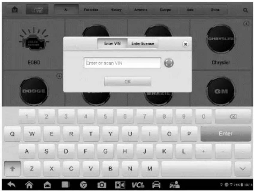
Figure 4-4 Manual VIN Input
-
Tap OK. The vehicle will be identified in a few seconds, and once the matching is successful, the system will guide you to the Vehicle Diagnostics screen directly.
-
Tap "x" to exit Manual Input.
Scan VIN/License
Tap Scan VIN/License (Figure 4-1) in the drop-down list. The camera will launch. On the right side of the screen, three options are available: Scan Bar Code, Scan VIN, and Scan License.

NOTE
The Scan License option is supported in certain countries and areas. If not available, manually enter the license number.
Select one of three options and position the tablet to align the VIN or license number within the scanning window, the result appears in the Recognition result dialog box after scanned. Tap OK to confirm the result, and then the vehicle information confirmation screen will appear on the tablet. If all the vehicle information is correct, tap the icon on the middle of the screen to confirm the VIN of the test vehicle. Tap OK to continue.

Figure 4-5 Sample Scan VIN Code 1
If the VIN/License number cannot be scanned, manually enter it after tapping the pen-shape icon. Tap OK to continue. Manually enter the license number and select a vehicle brand in the vehicle information confirmation screen. Tap the icon on the middle of the screen to confirm the VIN of the test vehicle. Tap OK to continue.
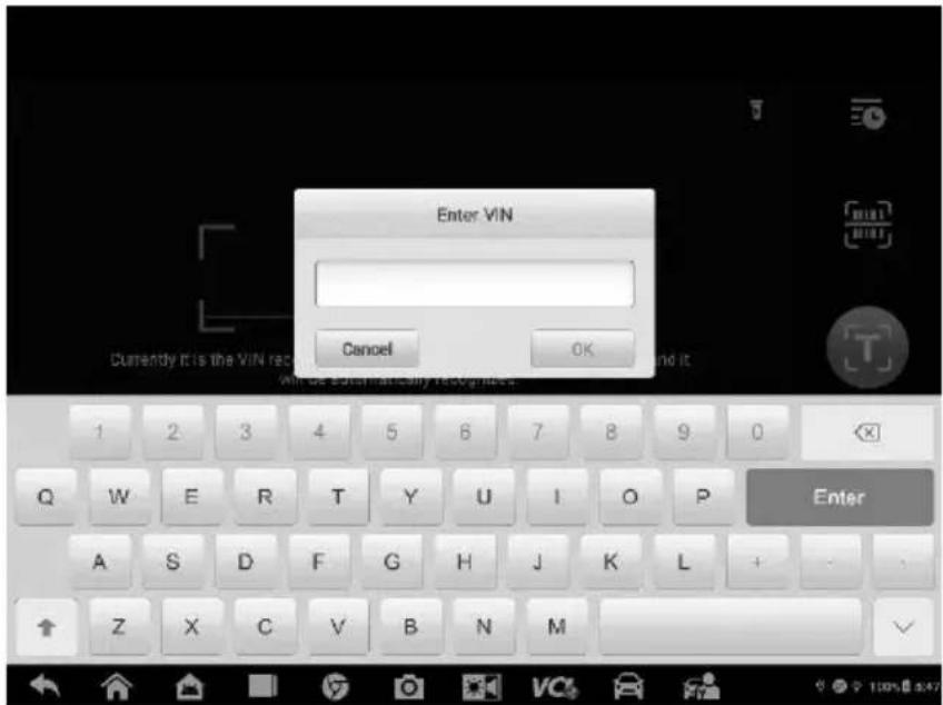
Figure 4-6 Sample Scan VIN Code 2
Manual Vehicle Selection
When the vehicle's VIN is not automatically retrievable through the vehicle's ECU, or when the specific VIN is unknown, you can choose to select the vehicle manually.
Step-by-step Vehicle Selection
This mode of vehicle selection is menu driven. Select the Manufacturer icon on the Vehicle Menu screen and the 'Select Diagnostic Type' screen appears. Then tap the Manual selection button. Select the vehicle information (e.g., the brand, model, capacity, engine type and model year) on the same screen. Tap the Reset button to reselect the vehicle information, if needed. The Esc button at the lower-right corner of the screen will bring you back to the previous screen.

Figure 4-7 Sample Manual Vehicle Selection Screen
Alternative Vehicle Identification
Occasionally, you may identify a test vehicle that the tester does not recognize; the database does not support, or has some unique characteristics that prevent it from communicating with the tester through the normal channels. In these instances, you are provided with the OBD direct entry, through which you can perform generic OBDII or EOBD tests. See Generic OBDII Operations for additional information.
Navigation
This section describes how to navigate the Diagnostics interface and select test options.
Diagnostics Screen Layout
The Diagnostics screens typically include four sections.
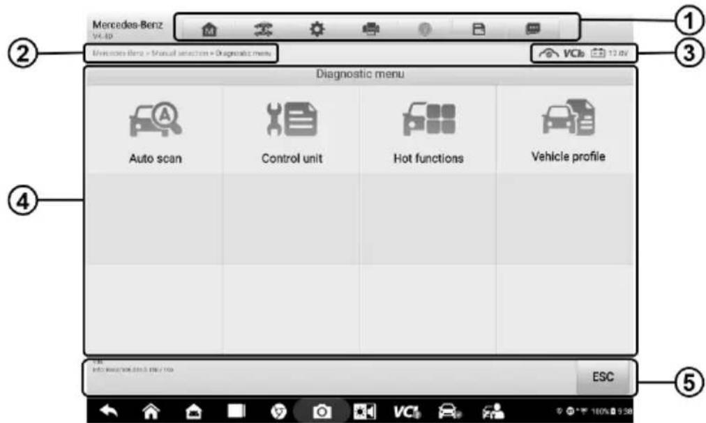
Figure 4-8 Sample Diagnostics Screen
① Diagnostics Toolbar
② Current Directory Path
③ Status Information Bar
④ Main Section
⑤ Function Buttons
Diagnostics Toolbar
The Diagnostics Toolbar contains a number of buttons that allow you to print or save the displayed data and make other controls. The table below provides a brief description for the operations of the Diagnostics toolbar buttons:
Table 4-2 Diagnostics Toolbar Buttons
| Name | Button | Description |
| Home |  | Returns to the MaxiSys Job Menu. |
| Vehicle Swap |  | Exits the diagnostic session and returns to the vehicle menu screen to select another vehicle for testing. |
| Settings |  | Opens the Settings screen. See Settings on page 64. |
 | Saves and prints a copy of the displayed data. See Printing Settings on page 65. | |
| Help |  | Provides instructions or tips for operations of various diagnostic functions. |
| Save |  | Opens a submenu for the 2 options to save data.Tap Save This Page to take a screenshot image.Tap Save All Data to save a PDF file (use this save option when data displays on multiple screens).These files are stored in Data Manager application for later reviews. See Data Manager on page 56. |
| Data Logging |  | Tap to display the error options. Select a specific abnormal type, and a submission form will appear to let you enter the report information. |
To print data in Diagnostics
- Tap the Diagnostics application button from the MaxiSys Job Menu. The Print button on the diagnostic toolbar is available throughout the whole Diagnostics operations.
- Tap Print and a drop-down menu appears.
a) Print This Page — prints a screenshot copy of the current screen.
b) Print All Page — prints a PDF copy of all displayed data.
- A temporary file will be created and sent to the computer for printing.
- When the file is transferred successfully, a confirmation message displays.

NOTE
Make sure the tablet is connected to the computer network, either via Wi-Fi or LAN, before printing. For more instructions on printing, see Printing Settings on page 65.
To submit Data Logging reports in Diagnostics
- Tap the Diagnostics application button from the MaxiSys Job Menu. The Data Logging button on the diagnostics toolbar is available throughout all Diagnostics operations.
- Tap the Options button to display the error options. Select a specific error, and a submission form will appear to let you enter the report information.
- Tap the Send button in the upper-right corner of the screen to submit the report via the Internet. A confirmation message appears when sent successfully.
Current Directory Path
The Directory Path shows all directory names to access the current page.
Status Information Bar
The Status Information Bar at the top of the Main Section displays the following items:
- Network Status Icon — indicates whether a network is connected.
- VCI Icon — indicates the communication status between the tablet and the VCI.
- Battery Icon — indicates the battery status of the vehicle.
Main Section
The Main Section of the screen varies depending on the stage of operations. The Main Section can show vehicle identification selections, the main menu, test data, messages, instructions and other diagnostic information.
Function Buttons
The displayed Function Buttons at this section of the screen vary depending on the stage of operations. They can be used to navigate, save or clear the diagnostic data, exit scanning as well as make other functional controls. The functions of these buttons will be introduced respectively in the following sections of the corresponding test operations.
Screen Messages
Screen messages appear when additional input is needed before proceeding. There are mainly three types of on-screen messages as to their purposes: Confirmation, Warning, and Error.
Confirmation Messages
These usually appear as an “Information” screen, which informs you when you are about to perform an action that cannot be reversed or when an action has been initiated and your confirmation is needed to continue.
When a user-response is not required to continue, the message appears briefly before disappearing.
Warning Messages
These appear when completing the selected action may result in an irreversible change or loss of data. The typical example for this is the “Erase Codes” message.
Error Messages
These appear when a system or procedural error has occurred. Examples of possible errors include a disconnected cable or communication interruption due to certain reasons.
Making Selections
The Diagnostics application is a menu driven program that presents a series of choices one at a time. As you select from a menu, the next menu in the series appears. Each selection narrows the focus and leads to the desired test. Use your fingertip or the stylus pen to make menu selections.
Main Menu
The Diagnostics application allows you to establish a data link to the electronic control system of the test vehicle via the VCI for vehicle diagnosis, service or programming. You can operate functional tests, retrieve vehicle diagnostic information such as trouble codes, event codes and live data, and perform ECU reprogramming, for various vehicle control systems, such as engine, transmission, ABS and more.
The Vehicle Diagnostics screen has two main parts:
- Diagnosis — a comprehensive section which includes all available functions: reading, clearing, saving and printing diagnostic information, as well as performing active tests and special functions.
- Hot functions — a separate section designed to perform vehicle scheduled service and maintenance, such as to reset the service lights and perform calibration for various systems.
After a section is selected and the tablet establishes communication with the vehicle via the VCI, the corresponding function menu or selection menu displays.
Diagnosis
There are two main functions of the Diagnosis section:
- Auto scan — starts auto scanning for all the available systems on the vehicle
- Control unit — displays a selection menu of all available control units of the test vehicle.
Auto Scan
The Auto Scan function performs a comprehensive scan of all the systems on the vehicle's ECU in order to locate fault systems and retrieve DTCs. A sample operation interface of Auto Scan appear as below:

Figure 4-9 Sample Auto Scan Operation Screen
① Navigation Bar
② Main Section
③ Function Buttons
Navigation Bar
- List Tab — displays the scanned data in list format
- Progress Bar — indicates the test progress
Main Section
■ Column 1 — displays the system numbers.
■ Column 2 — displays the scanned systems.
■ Column 3 — displays the diagnostic marks indicating different conditions of the test result.
- -!:- Indicates that the scanned system may not support the code reading function, or there is a communication error between the tester and the control system.
- -?:- Indicates that the vehicle control system has been detected, but the tester cannot accurately locate it.
✿ Fault | #: Indicates there is/are detected fault code(s) present; “#” indicates the number of the detected faults.
✿ Pass | No Fault: Indicates the system has passed the scanning process and no fault has been detected.
Not Scanned: Indicates the system has not been scanned.
✿ No Response: Indicates the system has not received a response.
■ Column 4 — performs further diagnosis and other test activities. A Function Menu screen (Figure 4-10) shall display when you tap the button.
Function Buttons
The table below provides a brief description of how the function buttons operate:
Table 4-3 Function Buttons in Auto Scan
| Name | Description |
| Report | Displays the diagnostics data in the report form. |
| Quick erase | Deletes codes. A warning message screen will appear to inform you of possible data loss when this function is selected. |
| Pause | Suspends scanning and changes to show the Continue button. |
| Enter system | Enters the ECU system. |
| ESC | Returns to the previous screen or exit Auto Scan. |
Control Unit
This option allows you to manually locate a required control system for testing through a series of choices. Follow the menu-driven procedure, the program will guide you to the Function menu screen.
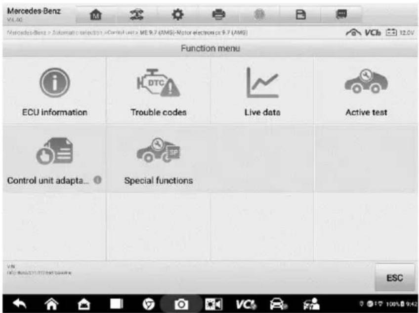
Figure 4-10 Sample Function Menu Screen
The Function menu options vary slightly for different vehicles. The Function menu may include:
- ECU information — provides the retrieved ECU information in detail. Selecting it opens an information screen.
- Trouble codes — contains Read Codes and Erase Codes. The former displays detailed DTC information retrieved from the vehicle control module, the latter facilitates you to erase DTCs and other data from the ECU.
- Live data — retrieves and displays live data and parameters from the vehicle's ECU.
● Active test — provides specific subsystem and component tests. This selection may appear as Actuators, Actuator Test, or Function Tests and the tests options vary depending on the vehicle manufacturer and model. - Special functions — provides component adaptation or variant coding functions for custom configurations, and also allows you to reprogram adaptive values for certain components after making repairs. Depending on the test vehicle, this selection may sometimes appear as Control Unit Adaptations, Variant Coding, Configuration or something similar.
NOTE
With the diagnostic toolbar on top of the screen throughout the whole diagnostic procedures, you are allowed to make various controls of the diagnostic information at any time, such as print and save the displayed data, get help information, or perform data logging.
To perform a diagnostic function
- Establish communication with the test vehicle via the VCI.
- Identify the test vehicle by selecting from the menu options.
- Locate the required system for testing by Auto scan or through menu driven selections in Control unit.
- Select the desired test from the Function menu screen.
ECU Information
This function retrieves and displays the specific information for the tested control unit, including unit type, version numbers and other specifications.

Figure 4-11 Sample ECU Information Screen
① Diagnostics Toolbar Buttons — see Table 4-2 Diagnostics Toolbar Buttons on page 27 for detailed descriptions of the operations for each button.
② Main Section — the left column displays the item names, and the right column displays the specifications or descriptions.
③ Function Button — in this case, only the ESC button is available. Tap it to exit after viewing.
Trouble Codes
Read Codes
This function retrieves and displays DTCs from the vehicle's control system. The Read Codes screen varies for each vehicle being tested, on some vehicles, freeze frame data can also be retrieved for viewing. The sample Read Codes screen appears as below:

Figure 4-12 Sample Read Codes Screen
① Diagnostics Toolbar Buttons — see Table 4-2 Diagnostics Toolbar Buttons on page 27 for details.
② Main Section
- Code Column — displays the retrieved codes from the vehicle.
- Status Column — indicates the status of the retrieved codes.
● Description Column — provides detailed descriptions for the retrieved codes. - Snowflake Icon — only displays when Freeze Frame data is available for viewing; Selecting it displays a data screen, which looks very similar to the Read Codes interface, therefore same operation methods may be applied.
③ Function Button
Table 4-4 Function Buttons in Trouble Codes
| Name | Description |
| DTC guide | Checks the related help information. |
| Freeze frame | Displays when freeze frame data is available for viewing; Tap the icon to display data screen. The Freeze Frame interface is similar to that of the Read Codes interface and share similar operations. |
| Search | Searches the selected DTC for additional information on the Internet. |
| Erase codes | Erases codes from the ECU. It is recommended that DTCs are read and needed repairs are performed before erasing codes. |
| Read codes | Retrieves and displays the DTCs from the vehicle control system. The Read Codes screen varies for each vehicle being tested. |
| ESC | Returns to the previous screen or exit Trouble Code. |
Erase Codes
After reading the retrieved codes from the vehicle and making repairs, you can erase the codes from the vehicle using this function. Before performing this function, make sure the vehicle's ignition key is in the ON (RUN) position with the engine off.
To erase codes
- Tap Trouble Codes from the Function Menu.
- Tap Erase Codes. A warning message appears to inform you of data loss when this function is applied.
a) Tap Yes to continue. A confirming screen appears when the operation is successfully done.
b) Tap No to exit.
- Tap ESC on the confirmation screen to exit Erase Codes.
- Check the Read Codes function again to ensure the operation is successful.
Live Data
When this function is selected, the screen displays the data list for the selected module. The parameters appear in the order that they are transmitted by the ECU, so expect variation among vehicles.
Gesture scrolling allows you to quickly move through the data list. Drag your finger up or down on the screen to reposition the parameters being displayed if the data occupies more than one screen. The figure below displays a typical Live Data screen:
![Mercedes-Benz 14.02 Mercedes-Benz + Automatic selections + Control unit > ECM/Vkor Electronics (ME) WESP for combustion engine (W372) > Live data 12.1V Name 0 items selected Engine speed 895.75 >=500.00 Rpm Alternator ID 1792 Terminal 61 status Off Battery voltage 14.04 [11.00...15.00] V Calculated alternator torque 0 Nm Electrical fault in alternator No No Mechanical fault in alternator No No Cancel All Browse selected Graph merge To top Setting Clear data Freeze Record Balance Back](/content/2026/05/979487/images/55ffe7cdc526751346e37470ad2ca6ba3e4b238dc9538c2c579d65cc4c9cb97f.jpg)
Figure 4-13 Sample Live Data Screen
① Diagnostics Toolbar Buttons — see Table 4-2 Diagnostics Toolbar Buttons for detailed descriptions of each button.
② Main Section
- Name Column — displays the parameters.
a) Check Box — tap the check box to the left of a parameter to select the item. Tap the check box again to deselect it.
b) Drop-down Menu — tap the drop-down menu to the right of the parameter to open a submenu, and view data display-mode options.
- Value Column — displays the values of the parameters.
- Range Column — displays the range of the parameters.
- Unit Column — displays the units of the parameter values.
To change the Unit mode, tap the Settings button in the top toolbar and select a required mode. See Unit.
Display Mode
There are four display modes available for data viewing, allowing you to view various parameters in the mode best suited to represent the data.
Tap the drop-down menu to the right of the parameter name to open a submenu. A total of 7 buttons will be displayed: The 4 buttons on the left represent different data display modes, plus an Information button (active when additional information is available), an Unit Change button (for switching the unit of displayed data), and a Trigger button (tap to open the "Trigger Settings" window).
![Mercedes-Benz V4.51 Mercedes-Benz > Automatic selection > Control unit > ECM Motor Electronics (ME) 'ME97 for combustion engine 'M272' >Live data VCB 12.1V Name 0 items selected Value Range Unit Engine speed 895.75 >=500.00 Rpm Battery voltage 14.04 [11.00...15.00] V Calculated alternator torque 0 Nm Electrical fault in alternator No No Mechanical fault in alternator No No Cancel All Show selected Graph merge To tap Setting Clear data Freeze Record Review Back](/content/2026/05/979487/images/e27a4afe55e316bced5f979713373af1eaded2c850b894016e61d4860d56be76.jpg)
Figure 4-14 Sample Display Mode Screen
Each parameter displays the selected mode independently.
✿ Analog Gauge Mode — displays the parameters in gauge charts.
✿ Text Mode — the default mode that displays the parameters as a text list.

NOTE
Some status parameters, such as a switch reading like ON, OFF, ACTIVE, and ABORT, can only be displayed in Text Mode. Others, such as a sensor reading, can be displayed in both text and graph modes.
✨ Waveform Mode — displays the parameters in waveform graphs.
In this mode, five control buttons will appear to the right of the parameter, allowing you to manipulate the display status.
![Mercedes-Benz > Automatic selection > Dental and > ECM(Motor Electronics (ME): MERT for combustion engine: MS72) > Live data V4.51 Mercedes-Benz > Automatic selection > Dental and > ECM(Motor Electronics (ME): MERT for combustion engine: MS72) > Live data V4.51 Name 1 items selected Value Range Unit Engine speed (Rpm) SutY 895.75 Alternator ID 1792 Terminal 61 status Off Battery voltage 14.04 [11.00...15.00] V Calculated alternator torque 0 Nm Electrical fault in alternator No No Mechanical fault in alternator No No Cancel All Show selected Graph merge To top Setting Clear data Freeze Record Review Quick](/content/2026/05/979487/images/14115fc01201d9d931f271702a5306a5c343fd8edf65729b568985da34cbb482.jpg)
Figure 4-15 Sample Waveform Graph Mode Screen
- Settings Button (SetY) — sets the minimum and maximum value of the Y-axis.
- Scale Button — changes the scale values.
There are two scale buttons displaying above the waveform graph to the right, which can be used to change the scale values of the X-axis and Y-axis of the graph. There are four scales available for the X-axis: x1, x2, x4 and x8, and three scales available for the Y-axis: x1, x2, and x4.
- Edit Button — edit the waveform color and line thickness.
- Zoom-in Button — tap once to display the selected data graph in full screen.
- Exit Button — tap to exit waveform mode.
Full Screen Display — this option is only available in waveform mode, and is mostly used in Graph Merge status for data comparison. There are three control buttons available on the top right side of the screen under this mode.
- Scale Button — tap to change the scale values below the waveform graph. There are four scales available for the X-axis: x1, x2, x4 and x8. There are three scales available for the Y-axis: x1, x2, and x4.
-
Edit Button — tap to open an edit window, in which you can set the waveform color and the line thickness displayed for the selected parameter.
-
Zoom-out Button — tap to exit full screen display.
- Exit Button — tap to exit waveform mode.
To edit the waveform color and line thickness in a data graph
- Select parameters to display in waveform mode.
- Tap the Edit button and an edit window will appear.

Figure 4-16 Sample Waveform Edit Screen
- The parameter is selected automatically in the left column.
- Select a color from the second column.
- Select a line thickness from the right column.
- Tap Done to save the settings and exit, or tap Cancel to exit without saving.

NOTE
In full screen display mode, you can edit the waveform color and line thickness by tapping the Edit button on the upper-right side of the screen.
Trigger Settings
Tap the drop-down button to the right of the parameter to open a submenu. The Trigger button is the last one in the submenu. Tap to display the Trigger Settings window.
On the Trigger Settings screen, you can set a standard range by filling in minimum and maximum values. When exceeding these values, the trigger function will be executed and the device will automatically record and save the generated data. You can review the saved live data by tapping the Review button at the bottom of the screen.
![Mercedes-Benz VCA 103 Mercedes-Benz Anti scale: BAN-Monier Cladexion (ME) VENF (or combustion engine MZ/2) > Live Date Name 1 items selected Engine speed Alternator ID Terminal 61 status Battery voltage Calculated alternator t Electrical fault in alter Mechanical fault in al Trigger Settings Trigger OK Buzzer alarm ON MIN 500.0 MAX 900.0 Cancel OK >=500.00 Rpm 1.00...15.00] V Nm No No Cancel All Show selected Glush merge To top Setting Clean data Flange Record Environ Im](/content/2026/05/979487/images/07a7904ab6e834a38816d1163232972d8d418315684a62750637531509c18d1e.jpg)
Figure 4-17 Sample Trigger Settings Screen
Two buttons and two input boxes are available in the Trigger Settings window.
a) Trigger — switches the trigger on and off. The trigger is ON by default.
b) Buzzer alarm — switches the alarm on and off. The alarm function makes a beeping sound as an alert when the data reading reaches the preset minimum or maximum point. The buzzer alarm will only sound at the first trigger.
c) MIN — tap this input box to display a virtual keyboard to enter a lower threshold value.
d) MAX — tap this input box to display a virtual keyboard to enter an upper threshold value.
To set a trigger
- Tap the drop-down button to the right of the parameter to open a submenu.
- Tap the Trigger button to the right of the submenu to open the Trigger Settings window.
- Tap the MIN input box and enter the minimum threshold value.
- Tap the MAX input box and enter the maximum threshold value.
- Tap OK to save the settings and return to the Live Data screen, or tap Cancel to exit without saving.
When the trigger is set, a trigger mark appears in front of the parameter. The mark is gray when it is not triggered, and turns orange when triggered. Moreover, two horizontal lines appear on each of the data graphs (when Waveform Mode is applied) to indicate the alarm point. The threshold lines are shown in different colors to differentiate them from the parameter waveforms.
Digital Gauge Mode — displays the parameters in the form of a digital gauge graph.
③ Function Buttons
The operations of the function buttons on the Live Data screen are described below:
✿ Cancel All — tap to cancel all selected parameters. Up to 50 parameters can be selected at one time.
Show Selected/Show All — tap to toggle between the two options; one displays the selected parameters, the other displays all the available items.
✿ Graph Merge — tap to merge selected data graphs (for Waveform Mode only). This function is very useful when comparing different parameters.

NOTE
This mode supports a Graph Merge of 2 to 5 digital parameters. Non-digital parameters are note supported.
To merge selected data graphs
1) Select parameters to be merged.
2) Tap the Graph Merge button at the bottom of the Live Data screen.
a) This mode only supports parameters that can be represented digitally. If non-digital parameters are selected, a message will display advising the user that the selected parameters are not supported in this mode and to select 2 to 5 digital parameters. Tap Got It button to return to the previous screen and select supported parameters.
b) When unsupported parameters are selected, a message will appear advising the user to selected only parameters that are supported. A message will also appear if more than 5 parameters have been selected. Please select 2 to 5 of the supported parameters and tap OK button to merge.
3) Tap Cancel Merging button at the bottom of the Live Data screen to cancel merge.
To Top — moves a selected data item to the top of the list.
Setting — tap to set the recording duration.
To set live data record duration
- Tap Setting button at the bottom of the Live Data screen.
- Tap the > button to the right of Recording Time After Trigger Bar and select a time length.
-
Tap OK to save the settings and return to the Live Data Settings screen; or tap the "X" button on the upper-right corner to exit without saving.
-
Tap Done at the upper-right corner of the Live Data Setting screen to confirm and save the settings, and return to the Live Data screen, or tap Cancel to exit without saving.
✨ Clear Data — tap to clear all cached live data.
✨ Freeze — displays a still capture retrieved data.
- Previous Frame – moves to the previous frame of frozen data.
● Next Frame — moves to the next frame of frozen data.
● Play/Pause — tap to play/pause the frozen data. - Resume — tap to exit the freeze data mode and return to normal data display.
Record — starts recording the live data of the selected data items. Tap the Record button at the bottom of the Live Data screen. A message will display prompting user to select parameters to record. Tap the Got It button to confirm. Scroll down and select data to record. Tap the Record button to start recording. Tap the Resume button to stop recording. The recorded live data can be viewed in the Review section at the bottom of the Live Data screen or in the Data Manager.
- Resume — tap to stop data recording and to return to normal data display.
- Flag — appears when the Record function is applied. Tap to set flags to note points of interest when recording data. Notes can be added during playback in Review or Data Manager. Select the preset flag to open a popup window and display a virtual keyboard to input notes.
Review — reviews the recorded data. Tap to display a recording list, and select an item to review.

NOTE
Only data recorded during the current operation can be reviewed on the Live Data screen. All historical recorded data can be reviewed in "Review Data" in the Data Manager application.
● Previous Frame — switches to the previous frame of recorded data.
● Next Frame — switches to the next frame of recorded data.
● Play/Pause — tap to play/pause recorded data.
● Show Selected — displays the selected parameters.
● Graph Merge — merges selected data graphs.
● Back — exits the Review screen and returns to the Live Data screen.
✨ Back — returns to the previous screen or exits the function.
Active Test
The Active Test function is used to access vehicle-specific subsystem and component tests. Available test vary by vehicle manufacturer, year, and model, and only the available tests display in the menu.
During an active test, the tester outputs commands to the ECU in order to drive the actuators. This test determines the integrity of the system or parts by reading the engine ECU data or by monitoring the operation of the actuators, such as toggling a solenoid, relay, or switch, between two operating states.
Selecting Active Test opens a menu of test options that varies by vehicle make and model. Selecting a menu option activates the test. Follow all screen instructions while performing tests. How and what information is presented on the screen varies according to the type of test being performed. Some toggle and variable control tests display Active Test Controls at the top of the screen with data stream information below, or vice versa.

Figure 4-18 Sample Active Test Screen
The function buttons at the lower-right corner of the Active Test screen manipulate the test signals. The operational instructions are displayed on the main section of the test screen. Simply follow the on-screen instructions and make appropriate selections to complete the tests. Each time when an operation is successfully executed, message such as “Command Finished,” “Activation Successful,” or something similar displays.
Tap the ESC function button to exit the test when finished.
Special Functions
These functions perform various component adaptations, allowing you to recalibrate or configure certain components after making repairs or replacement.
The main section of the Adaptation Operation screen displays a list of operational and vehicle status information, which mainly consists of three parts:
- The first part shows the preconditions or requirements for executing the operation being selected.
- The second part displays the current conditions of the vehicle control module being learned for comparison to the preconditions suggested by the second part. If the current condition of the control module is out of the suggested limit value, you must adjust the vehicle condition to meet the requirement.
- The last part displays the instruction of how to use the function button at the lower right corner of the screen to manipulate the teach-in operations.

Figure 4-19 Sample Adaptation Operation Screen
Read the information carefully and check the vehicle condition accordingly, when you are sure that the vehicle is ready to perform the adaptation, simply follow the instructions provided to make appropriate selections. When the operation is done, an execution status message, such as Completed, Finished or Successful, appears.
Tap the ESC button to exit the function.
Generic OBDII Operations
A fast-access option for OBDII/EOBD vehicle diagnosis is available on the Vehicle Menu screen. This option presents a quick way to check for DTCs, isolate the cause of an illuminated Malfunction Indicator Lamp (MIL), check monitor status prior to emissions certification testing, verify repairs, and perform a number of other services that are emissions-related. The OBD direct access option is also used for testing OBDII/EOBD compliant vehicles that are not included in the diagnostics database. Functions of the diagnostics toolbar buttons at the top of the screen are the same as those available for
specific vehicle diagnostics. See Table 4-2 Diagnostics Toolbar Buttons on page 27 for details.
General Procedure
To access the OBDII/EOBD diagnostics functions
- Tap the Diagnostics application button from the MaxiSys Job Menu. The Vehicle Menu appears.
- Tap the EOBD button. There are two options to establish communication with the vehicle.
● Auto Scan — select to establish communication using each protocol in order to determine which one the vehicle is broadcasting on.
- Protocol — select to open a submenu of various protocols. A communication protocol is a standardized way of data communication between an ECU and a diagnostic tool. Global OBD may use several different communication protocols.
- Select a specific protocol if the Protocol option is selected. Wait for the Function menu screen to appear.

Figure 4-20 Sample Function Menu
-
Select a function option to continue.
-
DTC & FFD
- I/M Readiness
- Live Data
- O2 Sensor Monitor
- On-Board Monitor
- Component Test
● Vehicle Information
- Vehicle Status

NOTE
Some functions are supported only on certain vehicles.
Function Descriptions
This section describes the various functions of each diagnostics option:
DTC & FFD
When this function is selected, the screen displays a list of Stored Codes and Pending Codes. When the Freeze Frame data of certain DTCs are available for viewing, a snowflake button will display on the right side of the DTC item. The Erase Codes function can be applied by tapping the function button at the lower bottom of the screen.

Figure 4-21 Sample DTC & FFD Screen
- Stored Codes
Stored codes are the current emission related DTCs from the ECU of the vehicle. OBDII/EOBD Codes have a priority according to their emission severity, with higher priority codes overwriting lower priority codes. The priority of the code determines the illumination of the Malfunction Indicator Light (MIL) and the codes erase procedure. Manufacturers rank codes differently, so expect to see differences between vehicles.
- Pending Codes
These are codes for which setting conditions were met during the last drive cycle, but need to be met on two or more consecutive drive cycles before the DTC actually sets. The intended use of this service is to assist the service technician after a vehicle repair and after clearing diagnostic information, by reporting test results after
a single driving cycle.
a) If a test failed during the driving cycle, the DTC associated with that test is reported. If the pending fault does not occur again within 40 to 80 warm-up cycles, the fault is automatically cleared from memory.
b) Test results reported by this service do not necessarily indicate a faulty component or system. If test results indicate another failure after additional driving, then a DTC is set to indicate a faulty component or system, and the MIL is illuminated.
- Freeze Frame
In most cases the stored frame is the last DTC that occurred. Certain DTCs, those that have a greater impact on vehicle emission, have a higher priority. In these cases, the highest priority DTC is the one for which the freeze frame records are retained. Freeze frame data includes a “snap shot” of critical parameter values at the time the DTC is set.
- Erase Codes
This option is used to clear all emission related diagnostic data such as, DTCs, freeze frame data and manufacturer specific enhanced data from the vehicle's ECU, and resets the I/M Readiness Monitor Status for all vehicle monitors to Not Ready or Not Complete status.
A confirmation screen displays when the clear codes option is selected to prevent accidental loss of data. Select Yes on the confirmation screen to continue, or No to exit.
I/M Readiness
This function is used to check the readiness of the monitoring system. It is an excellent function to use prior to having a vehicle inspected for compliance to a state emissions program. Selecting I/M Readiness opens a submenu with two choices:
- Since DTCs Cleared — displays the status of monitors since the last time the DTCs were erased.
- This Driving Cycle — displays the status of monitors since the beginning of the current drive cycle.
Live Data
This function displays the real time PID data from ECU. Displayed data includes analog inputs and outputs, digital inputs and outputs, and system status information broadcast on the vehicle data stream.
Live data can be displayed in various modes, see Live Data for detailed information.
O2 Sensor Monitor
This option allows retrieval and viewing of O2 sensor monitor test results for the most recently performed tests from the vehicle's on-board computer.
The O2 Sensor Monitor test function is not supported by vehicles that communicate using a controller area network (CAN). For O2 Sensor Monitor tests results of CAN-equipped vehicles, refer to On-Board Monitor.
On-Board Monitor
This option allows you to view the results of On-Board Monitor tests. The tests are useful after servicing or after erasing a vehicle's control module memory.
Component Test
This service enables bi-directional control of the ECU so that the diagnostic tool is able to transmit control commands to operate the vehicle systems. This function is useful in determining how well the ECU responds to a command.
Vehicle Information
The option displays the vehicle identification number (VIN), the calibration identification, and the calibration verification number (CVN), and other test vehicle information.
Vehicle Status
This item is used to check the current condition of the vehicle, including communication protocols of OBDII modules, retrieved codes amount, status of the Malfunction Indicator Light (MIL), and other additional information may be displayed.
Exit Diagnostics
The Diagnostics application remains open as long as there is an active communication with the vehicle. You must exit the diagnostics operation interface to stop all communications with the vehicle before closing the Diagnostics application.

NOTE
Damage to the vehicle Electronic Control Module (ECM) may occur if communication is disrupted. Make sure the all connections, such as data cable, USB cable, and wireless or wired network, are properly connected at all times during testing. Exit all tests before disconnecting the test cable or powering down the tool.
To exit the Diagnostics application
-
From an active diagnostic screen, tap the Back or ESC functional button to exit a diagnostic session step-by-step; Or
-
Tap the Vehicle Swap button on the diagnostics toolbar to return to the Vehicle
Menu screen.
From the vehicle menu screen, tap the Home button on the top toolbar; or tap the Back button on the navigation bar at the bottom of the screen. Or
- Tap the Home button on the diagnostics toolbar to exit the application directly to the MaxiSys Job Menu.
Now, the Diagnostics application is no longer communicating with the vehicle and it is safe to open other MaxiSys applications, or exit the MaxiSys Diagnostics System and return to the Android system's home screen.
5 Service
The Service section is specially designed to provide quick access to the vehicle systems for various scheduled service and maintenance tasks. The typical service operation screen is a series of menu driven executive commands. Follow on-screen instructions to select appropriate execution options, enter correct values or data, and perform necessary actions. The application will display detailed instructions to complete selected service operations.
After entering each special function, the screen will display two application parts: Diagnosis and Hot Functions. The Diagnosis enables the reading and clearing of codes which is sometimes necessary after completing certain special functions. Hot Functions consists of sub functions of the selected special function.
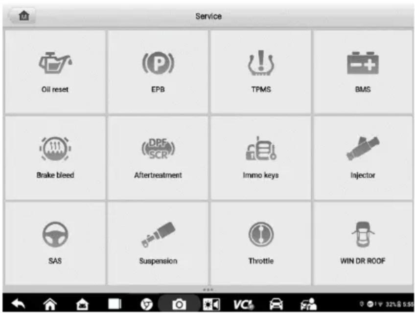
Figure 5-1 Sample Service Menu
In this chapter, we will discuss several of the most commonly used services.
Oil Reset Service
This function performs reset of the Engine Oil Life system, which calculates the optimal oil life change interval depending on the vehicle driving conditions and climate. The Oil Life Reminder must be reset each time the oil is changed, so the system can calculate when the next oil change is required.

NOTE
- Always reset the engine oil life to 100% after every oil change.
- All required work must be carried out before the service indicators are reset. Failure to do so may result in incorrect service values and cause DTCs to be stored by the relevant control module.
- For some vehicles, the scan tool can reset additional service lights such as the maintenance cycle and service interval. On BMW vehicles for example, service resets include engine oil, spark plugs, front/rear brakes, coolant, particle filter, brake fluid, micro filter, vehicle inspection, exhaust emissions inspection and vehicle checks.
Electric Parking Brake (EPB) Service
This function has a multitude of ways to maintain the electronic braking system safely and effectively. The applications include deactivating and activating the brake control system, assisting with brake fluid control, opening and closing brake pads, and setting brakes after disc or pad replacement.
EPB Safety
It can be dangerous to perform Electric Parking Brake (EPB) system maintenance, so before you begin the service work, please keep these rules in mind.
√ Ensure that you are fully familiar with the braking system and its operation before commencing any work.
√ The EPB control system may be required to be deactivated before carrying out any maintenance/diagnostic work on the brake system. This can be done from the tool menu.
√ Only perform maintenance work when the vehicle is stationary and on level ground.
√ Ensure that the EPB control system is reactivated after the maintenance work has been completed.

NOTE
Autel accepts no responsibility for any accident or injury arising from the maintenance of the Electric Parking Brake system.
Tire Pressure Monitoring System (TPMS) Service
This function allows you to quickly look up the tire sensor IDs from the vehicle's ECU, as well as to perform TPMS replacement and reset procedures after tire sensors are replaced.
Battery Management System (BMS) Service
The Battery Management System (BMS) allows the tool to evaluate the battery charge state, monitor the close-circuit current, register the battery replacement, activate the rest state of the vehicle, and charge the battery via the diagnostic socket.

NOTE
- This function is not supported by all vehicles.
- The sub functions and actual test screens of the BMS may vary by vehicle, please follow the on-screen instructions to make correct option selection.
The vehicle may use either a sealed lead-acid battery or an AGM (Absorbed Glass Mat) battery. Lead acid battery contains liquid sulphuric acid and can spill when overturned. AGM battery (known as VRLA battery, valve regulated lead acid) also contains sulphuric acid, but the acid is contained in glass mats between terminal plates.
It is recommended that the replacement aftermarket battery has the same specifications, such as capacity and type, as the exiting battery. If the original battery is replaced with a different type of battery (e.g. a lead-acid battery is replaced with an AGM battery) or a battery with a different capacity (mAh), the vehicle may require reprogramming of the new battery type, in addition to, performing the battery reset. Consult the vehicle manual for additional vehicle-specific information.
Steering Angle Sensor (SAS) Service
Steering Angle Sensor Calibration permanently stores the current steering wheel position as the straight-ahead position in the steering angle sensor EEPROM. Therefore, the front wheels and the steering wheel must be set exactly to the straight-ahead position before calibration. In addition, the vehicle identification number (VIN) is also read from the instrument cluster and stored permanently in the steering angle sensor EEPROM. On successful completion of calibration, the steering angle sensor fault memory is automatically cleared.
Calibration must always be carried out after the following operations:
- Steering wheel replacement
● Steering angle sensor replacement - Any maintenance that involves opening the connector hub from the steering angle sensor to the column
- Any maintenance or repair work on the steering linkage, steering gear or other related mechanism
● Wheel alignment or wheel track adjustment - Accident repairs where damage to the steering angle sensor, SAS assembly, or any part of the steering system may have occurred

NOTE
- Autel accepts no responsibility for any accident or injury arising from servicing the SAS system. When interpreting DTCs retrieved from the vehicle, always follow the manufacturer's recommendation for repair.
- All software screens shown in this manual are examples, actual test screens may vary by test vehicle. Pay attention to the menu titles and onscreen instructions to make correct option selections.
- Before starting any procedure, make sure vehicle has an ESC button. Look for button on dash.
Diesel Particle Filter (DPF) Service
The Diesel Particle Filter (DPF) function manages DPF regeneration, DPF component replacement teach-in and DPF teach-in after replacing the engine control unit.
The ECM monitors driving style and selects a suitable time to employ regeneration. Cars driven a lot at idling speed and low load will attempt to regenerate earlier than cars driven more with higher load and speed. In order for regeneration to take place, a prolonged high exhaust temperature must be obtained.
In the event of the car being driven in such a way that regeneration is not possible, i.e., frequent short journeys, a diagnostic trouble code will eventually be registered in addition to the DPF light and “Check Engine” indicators displaying. A service regeneration can be requested in the workshop using the diagnostic tool.
Before performing a forced DPF regeneration using the tool, check the following items:
● The fuel light is not on.
- No DPF-relevant faults are stored in system.
● The vehicle has the specified engine oil.
● The oil for diesel is not contaminated.

IMPORTANT
Before diagnosing a problem vehicle and attempting to perform an emergency regeneration, it is important to obtain a full diagnostic log and read out relevant measured value blocks.

NOTE
- The DPF will not regenerate if the engine management light is on, or there is a faulty EGR valve.
-
The ECU must be re-adapted when replacing the DPF and when topping up the fuel additive Eolys.
-
If the vehicle needs to be driven in order to perform a DPF service, a second person is needed for the function. One person should drive the vehicle while the other person observes the screen on the Tool. Do not attempt to drive and observe the scan tool at the same time. This is dangerous and puts your life and the lives of other motors and pedestrians at risk.
Immobilizer (IMMO) Service
An immobilizer is an anti-theft mechanism that prevents an automobile's engine from starting unless the correct ignition key or other device is present. This device prevents thieves from starting the car by a method known as hot wiring. Most new vehicles have an immobilizer as standard equipment. An important advantage of this system is that it doesn't require the car owner to activate it; it operates automatically. An immobilizer is considered as providing much more effective anti-theft protection than an audible alarm alone; many auto insurance companies offer lower rates for vehicles that are equipped with an immobilizer.
As an anti-theft device, an immobilizer disables one of the systems needed to start a car's engine, usually the fuel supply or the ignition. This is accomplished by radio frequency identification between a transponder in the ignition key and a radio frequency reader in the steering column. When the key is placed in the ignition, the transponder sends a signal with a unique identification code to the reader, which relays it to a receiver in the vehicle's computer control module. If the code is correct, the computer allows the fuel supply and ignition systems to operate and start the engine. If the code is incorrect or absent, the computer disables the system, and the engine will be unable to start until the correct key is placed in the ignition.
The IMMO service can disable a lost vehicle key and program the replacement key fob. One or more replacement key fobs can be programmed.
6
ADAS
Advanced Driver Assistance Systems (ADAS) is an array of vehicle systems that aid the driver either through passive alerts or by active control of the vehicle to drive safer and with greater awareness and precision.
Cameras, sensors, ultrasound, radar and LIDAR are some of the systems used to capture the driving environment data, including travelling or static vehicles position, pedestrian location, road sign, driving lane and intersection detection, road (curves) and driving conditions (poor visibility or evening driving). Use that information to instruct the vehicle to take its predetermined action. Cameras, sensors and sensing systems are typically located in front and rear bumpers, windshield, front grill, and side and rear view mirrors.
Autel ADAS Calibration Tool provides comprehensive and precise ADAS calibration.
- Covers many vehicle makes, including Benz, BMW, Audi, Volkswagen, Porsche, Infiniti, Lexus, GM, Ford, Volvo, Toyota, Nissan, Honda, Hyundai, and Kia.
-
Supports the calibration of multiple driver assistant systems, including Adaptive Cruise Control (ACC), Night Vision System (NVS), Lane Departure Warning (LDW), Blind Spot Detection (BSD), Around View Monitoring (AVM), Rear Collision Warning (RCW) and Heads-up Displays (HUD).
-
Provides graphic illustrations and step-by-step instructions.
-
Provides demos to guide the technician through the calibration.

Figure 6-1 Autel ADAS Introduction Screen
7 Data Manager
The Data Manager allows you to store, print, and review saved files, manage the workshop information, customer information records and store test vehicle records.
Tap the Data Manager to open the file system menu. There are eight functions available.

Figure 7-1 Sample Data Manager Main Screen
The table below describes each of the function buttons in the Data Manager.
Table 7-1 Buttons in Data Manager
| Button | Name | Description |
 | Vehicle History | Tap to view the diagnostic records. |
 | Workshop Information | Tap to view or edit the workshop profile information. |
 | Customer | Tap to create a new customer account file. |
 | Image | Tap to view saved screenshots. |
 | Tap to view diagnostic reports. | |
 | Review Data | Tap to view recorded data. |
 | Uninstall Apps | Tap to uninstall applications. |
 | Data Logging | Tap to view communications with Autel support service and ECU information for the test vehicle. The saved data can be reported and sent to the technical center via the Internet. |
Vehicle History
This function stores vehicle test records, including vehicle information and the retrieved DTCs from previous diagnostic sessions. Test information is summarized and displayed in an easy-to-read table listing. The Vehicle History also provides direct access to the previously tested vehicle and allows you to directly restart a diagnostic session without needing to perform auto or manual vehicle selection.

Figure 7-2 Sample Vehicle History Screen
① Top Toolbar Buttons — navigation and application controls.
② Main Section — displays all the test records.
To activate a test session for a recorded vehicle
- Tap Data Manager on the MaxiSys Job Menu.
- Select Vehicle History to open the screen. Tap Diagnostics or Service to select diagnostic test records or service test records.
-
Tap Diagnostics icon at the bottom of the thumbnail of a vehicle record item.
-
The Diagnostics screen of the vehicle displays and a new diagnostics session is activated (See Diagnostics for detailed instructions on vehicle diagnostics operations), or select a vehicle thumbnail to select a record. A Test Records window appears. Review the recorded information of the test vehicle, and tap the Diagnostics button on the upper-right corner to continue diagnostics.
Test Records
A Test Record is a detailed data form of the tested vehicle, which includes general vehicle information, service record, customer information, and the diagnostic trouble codes retrieved from previous test sessions. Technician Notes will also display if present.

NOTE
The MaxiSys tablet must establish a connection to the VCI to restart test sessions on a previously tested vehicle.

Figure 7-3 Sample Test Records Sheet
To edit a previous Test Record
- Tap Data Manager in the MaxiSys main screen.
- Select Vehicle History.
- Select the specific vehicle history record thumbnail from the main section. The test record will display.
- Tap the Edit button (the pen icon) to start editing.
- Tap each item to enter information or attach files or images.
-
Tap Add a Customer to associate the Test Records sheet to an existing customer account, or add a new account to be associated with the test vehicle record. See Customer for more information.
-
Tap Done to save the updated record, or tap Cancel to exit without saving.

NOTE
The vehicle VIN, license number and customer account are associated by default. Vehicle records will automatically be associated using this vehicle and customer identification.
Workshop Information
Workshop Information allows you to enter, edit, and save detailed workshop profile information, such as shop name, address, phone number and other remarks, which, when printing vehicle diagnostics reports and other associated test files, will appear as the header of your printed documents.

Figure 7-4 Sample Workshop Information Sheet
To edit the Workshop information sheet
- Tap Data Manager on the MaxiSys Main Screen.
- Select Workshop Information.
- Tap on each field to enter the corresponding information.
- Tap Done to save the updated workshop information, or tap Cancel to exit without saving.
Customer
The Customer function allows you to create and edit customer accounts. It helps you to save and organize all customer accounts associated with the test vehicle records.
To create a customer account
- Tap the Data Manager application on the MaxiSys main screen.
- Select Customer.
- Tap the Add a customer button. A blank information form appears. Tap each field to enter the appropriate information.

NOTE
Required fields are denoted by an asterisk.
- For customers with more than one vehicle for service, tap Add New Vehicle Information. To delete the added vehicle information, tap the ✗ button.
- Tap OK on the upper-right corner of the screen to save the customer information, or tap Cancel to exit without saving.
To edit a customer account
- Tap Data Manager on the MaxiSys Job Menu.
- Select Customer.
- Select a customer account by tapping the corresponding name card. The Customer Information record displays.
- Tap Edit on the top toolbar to start editing.
- Tap on the input field to edit the information.
- Tap Complete to save the updated information, or tap Cancel to exit without saving.
To delete a customer account
- Tap Data Manager on the MaxiSys Job Menu.
- Select Customer.
- Select a customer account by tapping the corresponding name card. The Customer Information record appears.
- Tap Edit on the top toolbar to start editing.
- Tap Delete button on the top of the screen. A reminder message appears.
- Tap OK to confirm the command, and delete the account. Tap Cancel to cancel the request.
Image
The Image section is a database containing all captured screenshots in .png file format.
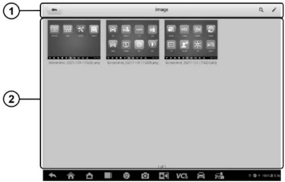
Figure 7-5 Sample Image Database Screen
- Toolbar Buttons — edits, prints or deletes the image files. See Table 7-2 Toolbar Buttons Description for detailed information.
- Main Section — displays the stored images.
Table 7-2 Toolbar Buttons Description
| Name | Button | Description |
| Back |  | Return to the previous screen. |
| Search |  | Enter the search page. |
| Edit |  | Display the editing toolbar to print, delete or view image. |
| Cancel |  | Close the editing toolbar or cancel file search. |
| Search |  | Quickly searches the image by entering the time of the screenshot. |
 | Print the selected image. | |
| Delete |  | Delete the selected image. |
 | Send the selected image via email. |
To edit/delete image(s)
- Select Data Manager from the MaxiSys Job Menu.
-
Select Image to access the image database.
-
Tap Edit on the top-right corner of the window. The editing screen appears.
- Select the image(s) you want to edit by tapping the check box at the bottom-right corner of the image.
- Tap Delete to delete the selected images or delete all images. Tap Print icon to print the selected image(s). Tap Email to attach the selected image(s) to an email.
PDF Files
The PDF section stores and displays all PDF files of saved data. After entering the PDF database, select a file to view.
This section uses the standard Adobe Acrobat Reader application for file viewing and editing. Please refer to the Adobe Acrobat Reader manual for more detailed instructions.
Review Data
The Review Data function allows you to play back the recorded data frames from live data streams.
On the Review Data main screen, select a record to play back.

Figure 7-6 Sample Data Playback Screen
① Main Section — displays the recorded data frames.
② Navigation Toolbar — allows you to operate data playback.
Use the Navigation Toolbar buttons to play back the record data from frame to frame.
Tap Back to exit data playback.
Uninstall Apps
This section allows you to manage the firmware application installed on the MaxiSys Diagnostics System. Selecting this section opens a management screen, on which you can check all the available vehicle diagnostics applications.
Select the vehicle firmware you want to delete by tapping on the vehicle brand icon, after which the selected item will display a blue check mark on the upper-right corner. Tap the Delete button on the top bar to delete the firmware from the system database.
Data Logging
The Data Logging section allows you to launch the Support platform to view records with or without feedback (saved) data logs on the diagnostics system. For more information, please refer to Data Logging.
8 Settings
Selecting Settings application opens a setup interface, on which you can adjust default setting and view information about the MaxiSys system. The following options are available for the MaxiSys system settings:
- Unit
- Language
- Printing Settings
- Auto Update
- ADAS Settings
- Vehicle List
- System Settings
- About
Operations
This section describes the operation procedures for the settings.
Unit
This option allows you to adjust the unit of measurement for the diagnostics system.
To adjust the unit setting
- Tap the Settings application on the MaxiSys Job Menu.
- Tap the Unit option on the left column.
- Select the appropriate unit of measurement (metric unit or imperial unit). A check mark will display to the right of the selected unit.
- Tap the Home button on the top-left corner to return to the MaxiSys Job Menu, or select another settings option for further system setup.
Language
This option allows you to adjust the display language of the MaxiSys system.
To adjust the language setting
- Tap the Settings application on the MaxiSys Job Menu.
-
Tap the Language option on the left column.
-
Select the required language. A check mark will display to the right of the selected language.
- Tap the Home button on the top left corner to return to the MaxiSys Job Menu, or select another setting option for further system setup.
Printing Settings
This option allows you to print any data or information anywhere and anytime either via PC network or Wi-Fi.
To setup a printer connection
- Tap Settings on the MaxiSys Job Menu.
- Tap Printing Settings on the left column.
- Tap the Print via Network item to activate the printing function, which enables the device to send files to the printer through the PC via Wi-Fi or Ethernet connection.
- Tap Home on the top-left corner to return to the MaxiSys Job Menu, or select another setting option for further system setup.
Printing Operations
To install the MaxiSys Printer driver
- Download Maxi PC Suite from www.autel.com > Support > Downloads > Autel Update Tools, and install to a Windows-based computer.
- Double click on Setup.exe item.
- Select the installation language to launch the installation wizard.
- Follow the instructions on the screen and Click Next to continue.
- Click Install and the printer driver will be installed onto the computer.
- Click Finish to complete the installation.
NOTE
The MaxiSys Printer runs automatically after the installation.
This section describes how to receive file from the MaxiSys tablet and perform printing through the computer:
To print from a computer
- Install the printer driver to the computer.
- Before printing, make sure the tablet is connected to the computer network, either via Wi-Fi or LAN.
- Run the MaxiSys Printer program on the computer.
-
Click Test Print to make sure the printer is working successfully.
-
Tap the Print button on the toolbar of the tablet. A test document will be sent to the computer.
- If the Auto Print option in the MaxiSys Printer is selected, the MaxiSys Printer will print the received document automatically.
- If the Auto Print option is not selected, click Open PDF File button to view all the temporary files. Select the file(s) to print and click Print.

NOTE
Make sure the computer with the Printing Services program installed is connected to a printer.
Auto Update
This option allows you to set the specific time for updating software automatically. There are three update options: OS Update, MaxiSys Update and Vehicle Update.
Tap ON/OFF to enable Auto Update. If the connectivity is enabled the button turns blue, or if disabled the button turns gray. Then set the time of the day for updating. If a specific time is set, the selected software will be automatically updated at this specific time.
ADAS Settings
This option allows you to perform ADAS calibrations with the MaxiSys tablet. Prior to using this function, please make sure that you have purchased an ADAS application card, and one of the Autel ADAS packages with the ADAS calibration frame.
To adjust the ADAS settings
-
Confirm that updates for the registered MaxiSys tablet are available.
-
Tap the Settings application on the MaxiSys Job Menu.
-
Make sure that the internet is available. Select ADAS Settings on the left column.
-
Scan the QR code on the ADAS frame to bind, or manually input frame serial number when QR code is not available.
-
Enter the verification code from the ADAS Calibration Card.
-
The system will reset and the main screen will display once registration has been completed.
Vehicle List
This option allows you to sort the vehicles either by alphabetic order or by frequency of use.
To adjust the vehicle list setting
- Tap the Settings application on the MaxiSys Job Menu.
- Select Vehicle List on the left column.
- Select the desired sort order. A check mark will display on the right of the selected sort type.
- Tap the Home button on the top-left corner to return to the MaxiSys Job Menu, or select another setting option for further system setup.
System Settings
This option provides you a direct access to the Android background system settings interface, on which you can adjust various system settings for the Android operating system, regarding wireless and networks settings, various device settings such as sound and display, as well as system security settings, and check the associated information about the Android system. Refer to your Android documentation for additional information.
About
The About option provides information about the MaxiSys diagnostics device including the product name, version, hardware, and serial number.
To check the MaxiSys product information in About
- Tap the Settings application on the MaxiSys Job Menu.
- Tap the About option on the left column. The product information screen displays on the right.
- Tap the Home button on the top left corner to return to the MaxiSys Job Menu, or select another setting option for further system setup.
9 Update
The Update application allows you to download the latest released software. The updates can improve the MaxiSys applications' capabilities, typically by adding new tests, new models, or enhanced applications to the database.
The tablet automatically searches for available updates for all of the MaxiSys software when it is connected to the Internet. Any updates that are found can be downloaded and installed on the device. This section describes installing an update to the MaxiSys Diagnostics System.

Figure 9-1 Sample Update Screen
① Navigation and Controls
- Home Button — returns to the MaxiSys Job Menu.
- Update All — displays available updates for all tablet systems.
● Show Recent — shows recent updates. - Refresh — refreshes the available update list.
- Search — searches specific update item by entering the file name, for example: a specific vehicle make.
② Status Bar
● Left Side — displays the MaxiSys device model information and serial number.
● Right Side — displays an update progress bar indicating the completion status.
③ Main Section
● Left Column — displays vehicle logos and update software version information.
- Middle Column — displays a brief introduction about the new changes to the software operation or capabilities. Tap the ⓘ button to view more details, and tap the dim area outside the information box to close the window.
- Right Column — depending on the operation status of each software item, the button displays differently:
a) Tap Update to update the selected item.
b) Tap Pause to suspend the updating procedure.
c) Tap Continue to continue updating a paused update.
To update the software
- Power up the tablet and ensure that it is connected to a power source and has a steady Internet connection.
- Tap the Update application button from the MaxiSys Job Menu; or tap the update notification message when received. The Update application screen appears.
-
Check all available updates:
-
If you decide to update all the items, tap the Update All button.
-
If you only want to update some individual items, tap the Update button on the right column of the specific item.
-
Tap the Pause button to suspend the updating process. Tap Continue to resume the update and the process will continue from the pause point.
-
When the updating process is completed, the software will be installed automatically. The new version will replace the older version.
10 VCI Manager
The VCI Manager is for connecting the MaxiSys tablet with a VCI through Bluetooth. This application allows you to pair the tablet with the VCI and to check its communication status.

Figure 10-1 Sample VCI Manager Screen
VCI Connection via Bluetooth
The VCI needs to be either connected to a vehicle or to an available power source, so that it is powered up during the synchronization procedure. Make sure the tablet has a fully charged battery or is connected to an external power supply.

Figure 10-2 Sample VCI Bluetooth Pairing Screen
To pair the VCI with the tablet via Bluetooth
- Power on the tablet.
- Connect one end of the main cable to the VCI's vehicle data connector.
- Connect the other end of the main cable to the vehicle Data Link Connector (DLC).
- Tap VCI Manager on the MaxiSys Job Menu of the tablet.
- Select VCI BT (short for VCI Bluetooth), from the connection mode list.
- Toggle Bluetooth ON. The device will start searching for available units for pairing.
- Depending on the VCI you use, the device name may appear as "Maxi" suffixed with the serial number. Select the appropriate device for pairing.
- When paired successfully, the connection status reads as "Connected."
- After a few seconds, the VCI button on the system Navigation Bar at the bottom of the screen will display a green badge, indicating that the tablet is connected to the VCI.
- To disconnect the device, tap the connected device again.
- Tap Back icon on the top-left to return to the MaxiSys Job Menu.

NOTE
A VCI can be paired with only one tablet at a time, and once it's been paired, the device will not be discovered by any other unit.
BAS Connection via Bluetooth
The MaxiBAS BT506 device needs to be either connected to a vehicle or to an available power source, so that it is powered up during the synchronization procedure. Make sure the tablet is fully charged or is connected to an external power supply.

Figure 10-3 Sample Battery Tester Bluetooth Pairing Screen
To pair the BT506 series tester with the tablet
- Press and hold the Power Button to turn on the MaxiSys tablet. Ensure that the unit is sufficiently charged before using.
- Power on the MaxiBAS BT506.
- Tap VCI Manager on the MaxiSys Job Menu of the tablet.
- Select BAS BT from the connection mode list.
- Toggle Bluetooth ON. The tablet automatically scans for an available battery tester for Bluetooth pairing. The device name will appear as "Maxi" suffixed with a serial number.
- Check the serial number of your BT506 series tester and select the desired device on the tablet for pairing.
- When paired successfully, the connection status will read as "Connected."
- To disconnect the device, tap the connected device again.
- Tap Back icon on the top-left to return to the MaxiSys Job Menu.
VCI Update
The VCI Update module provides the latest update for the VCI. Before updating the VCI, please make sure your tablet network is stable.

Figure 10-4 Sample VCI Update Screen
To update the VCI
- Power on the tablet.
- Connect the VCI to the tablet via Bluetooth or USB.
- Tap VCI Manager on the MaxiSys Job Menu of the tablet.
-
Select VCI Update from the connection mode list.
-
The current version and the latest version of the VCI will appear. Tap Update Now to update the VCI.
BAS Update
The BAS Update module provides the latest update for the MaxiBAS BT506. Before updating the BT506 series tester, please make sure your tablet network is stable.

Figure 10-5 Sample BAS Update Screen
To update the MaxiBAS BT506
- Power on the tablet and the MaxiBAS BT506.
- Connect the MaxiBAS BT506 device to the tablet via Bluetooth or USB.
- Tap VCI Manager on the MaxiSys Job Menu of the tablet.
- Select BAS Update from the connection mode list.
- The current version and the latest version of the MaxiBAS BT506 will appear. Tap Update Now to update the MaxiBAS BT506.
11 Remote Desktop
The Remote Desktop application launches the TeamViewer Quick Support program, which is a simple, fast, and secure remote-control interface. You can use the application to receive ad-hoc remote support from Autel's support center, colleagues, or friends by allowing them to control your MaxiSys tablet on their PC via the TeamViewer software.
Operations
If you think of a TeamViewer connection as a phone call, the TeamViewer ID would be the phone number under which all TeamViewer Clients can be reached separately. Computers and mobile devices that run TeamViewer are identified by a unique global ID. The first time the Remote Desktop application is started, this ID is generated automatically based on the hardware characteristics and will not change.
Make sure the tablet is connected to the Internet before launching the Remote Desktop application, so that the tablet is able to receive remote support from the third party.
Figure 11-1 Sample Remote Desktop Screen
To receive remote support from a partner
- Power on the tablet.
- Tap the Remote Desktop application on the MaxiSys Job Menu. The TeamViewer interface appears and the device ID is generated and displayed.
- Your partner must install the Remote Control software to their computer by downloading the TeamViewer program (full version) online (http://www.teamviewer.com). Start the software on their computer at the same
time, in order to provide support and take control of the tablet remotely.
- Provide your ID to the partner, and wait for them to send you a remote control request.
- A message displays to ask for your confirmation to allow remote control on your device.
- Tap Allow to accept, or tap Deny to reject.
Refer to the associated TeamViewer documents for additional information.
12 Support
This application launches the Support platform which synchronizes Autel's online service base station with the MaxiSys tablet. In order to synchronize the device to your online account, you need to register the product through the Internet when you use it for the first time. The Support application is connected to Autel's service channel and online communities that provides the quickest way for problem solutions, allowing you to submit complaints or send help requests to obtain direct service and support.
Product Registration
In order to get access to the Support platform and obtain update and other services from Autel, you are required to register the MaxiSys Diagnostic Device the first time you use it.
To register the diagnostic device
- Visit the website: http://pro.autel.com.
- On the Sign In page, enter your account ID and other information to log in, if you already have an account.
- If you are a new member to Autel and do not have an account yet, tap the Create an Autel ID button on the left side.
- Enter the required information in the input fields and tap the Get Verification Code button to get the verification code for email validation.
- The online system will automatically send a verification code to the registered email address. Enter the code in the Verification Code field and fill in the other input fields. Read through Autel's Terms and Conditions and tap Agree, and then tap Create an Autel ID at the bottom. A product registration screen opens.
- Find out the device's serial number and password from the About section of the Settings application on the tablet.
- Select your product model, enter the product serial number and password on the Product Registration screen, and tap Submit to complete the registration procedure.
Support Screen Layout
The main section of the Support screen is divided into two sections. The narrow column on the left is the main menu; selecting one subject from the main menu displays the corresponding functional interface on the right.

Figure 12-1 Sample Support Application Screen
My Account
The My Account screen displays the comprehensive information of the user and the product, which is synchronized with the online registered account, including User Info, Device Info, Update Info and Service Info.
Personal Info
The User information and Device information are both included under the Personal Info section.
- User information — displays detailed information of your registered online Autel account, including your Autel ID, Real name, Country/District, Town/City, Company/Institute, Address and Post code.
● Device information — displays the registered product information, including the Product serial number, Registration time, Expire time, and Warranty period.
Update Info
The Update Info tab displays a detailed record list of the product's software update history, including the product serial number, software version or name, and the update time.
Service Info
The Service Info tab displays a detailed record list of the device's service history information. Every time the device has been sent back to Autel for repair, the device's serial number and the detailed repair information, including Service date, Type of faults, and Repair content, will be recorded and updated to the associated online product account, which will be synchronized to the Service Info section.
Training
The Training section provides quick links to Autel's online video library. Select a video channel by language to see all available Autel online tutorial videos on such topics as product usage techniques and vehicle diagnostics practices.
Data Logging
The Data Logging screen keeps records of all Feedback (submitted), No feedback (saved) or History (up to the latest 20 test records) data loggings on the diagnostic system. The support personnel receive and process the submitted reports through the Support platform, and send back problem solutions within 48 hours to the corresponding Data Logging session, on which you are also allowed to have a direct conversation with the support personnel.
![2021-12-19_17-29-56[Other errors] Open D080 Dec 19th,2021 12:30](/content/2026/05/979487/images/3ac90a7a926ed2f8421e2e7b694ca31fc4433cdeb5153f02ec1c77059b856725.jpg)
Figure 12-2 Sample Data Logging Screen
To make a reply in a Data Logging session
- Tap Feedback tab to view the list of submitted data loggings.
- Select a specific item to view the latest update of the processing progress.
- Tap the text field at the bottom of the screen and enter the texts. Additionally, you may tap the Audio button to record a voice message or tap the Camera button to take a picture.
- Tap Send to deliver your message to the technical center.
FAQ
The FAQ section provides you comprehensive and abundant references for all questions frequently asked and answered about the use of Autel's online member account, shopping and payment procedures.
- Account — displays questions and answers about the use of Autel's online user account.
- Shopping & Payment — displays questions and answers about online product purchases and payment methods or procedures.
13 Battery Test
The MaxiBAS BT506 is a battery and electrical system analysis tool that uses Adaptive Conductance, an advanced battery analysis method to produce a more accurate examination of the battery's cold cranking ability and reserve capacity, which is vital to determining a battery's true health. The MaxiBAS BT506 enables technicians to view the health status of the vehicle's battery and electrical system. Together with the MaxiBAS BT506, this application can complete battery & starting and charging system tests and display the test results.
MaxiBAS BT506 Tester
Function Descriptions

Figure 13-1 MaxiBAS BT506 Tester
① Power Button
② Status LED
③ Power LED
4 USB Port
⑤ Battery Clamp Cable
Table 13-1 LED Description
| LED | Color | Description |
| Status LED | Flashing Green | The tester is communicating via USB cable. |
| Flashing Blue | The tester is communicating via Bluetooth. | |
| Flashing Red | Battery clamps are connected to the wrong battery terminals. | |
| Power LED | Solid Green | The tester is powered on and the battery is sufficiently charged. |
| Flashing Green | The tester is charging. (Becomes solid green when battery is fully charged.) | |
| Solid Red | The device is in boot mode. | |
| Flashing Red | The battery level is low. Please charge. |
Power Sources
The MaxiBAS BT506 tester can receive power from the following sources:
- Internal battery pack
- AC/DC power supply
IMPORTANT
Do not charge the battery when the temperature is below 0^ (32°F) or above 45^ (113°F).
Internal Battery Pack
The MaxiBAS BT506 tester can be powered with the internal rechargeable battery.
AC/DC Power Supply — Using Power Adapter
The MaxiBAS BT506 tester can be powered from an electrical outlet using the AC/DC power adapter. The AC/DC power supply also charges the internal battery pack.
Technical Specifications
Table 13-2 Technical specifications
| Item | Description |
| Connectivity | ● USB 2.0, type C● Bluetooth 4.2 |
| Input Voltage | 5 V DC |
| Working Current | < 150 mA at 12 V DC |
| Internal Battery | 3.7 V/800 mAh Lithium-ion polymer battery |
| CCA Range | 100 to 2000 A |
| Voltage Range | 6 to 36 V |
| Working Temperature | -10 to 50 °C(14 to 122 °F) |
| Storage Temperature | -20 to 60 °C (-4 to 140 °F) |
| Dimension (L x W x H) | 107 mm (4.21") x 75 mm (2.95") x 26 mm (1.02") (clamp cable not included) |
| Weight | 320 g (0.7 lb.) |
Test Preparation
Inspect the Battery
Before starting a test, observe the battery for:
- Cracking, buckling or leaking (If you see any of these defects, replace the battery.)
- Corroded, loose or damaged cables and connections (Repair or replace as needed.)
- Corrosion on the battery terminals, and dirt or acid on the case top (Clean the case and terminals using a wire brush and a mixture of water and baking soda.)
Connect the Battery Tester
To pair the BT506 with the MaxiSys tablet
- Press and hold the Power Button to turn on both MaxiSys tablet and BT506. Ensure that the unit is sufficiently charged before using.
- Enable Bluetooth on the MaxiSys tablet by tapping VCI Manager > BAS BT, and the tablet automatically scans for an available tester for Bluetooth pairing. The device name will appear as "Maxi" suffixed with the device serial number.
-
Check the serial number of your BT506 series tester and select the desired device for pairing.
-
When paired successfully, the connection status will read as "Connected" and the Status LED will flash blue.

Figure 13-2 Connecting with the Tablet
To connect to a battery
Connect the red clamp to the positive (+) terminal and the black clamp to the negative (-) terminal of the battery.

natural_image
Technical line drawing of a device connected to a clamp device (no text or symbols present)Figure 13-3 Connecting to a Battery
In-vehicle Test
In-vehicle Test is used for testing batteries that are installed in a vehicle. An in-vehicle test includes Battery Test, Starter Test, and Generator Test. These tests help determine the health status of the battery, the starter, and the generator.
IMPORTANT
Before using the diagnostic functions, download the desired vehicle software on the Update screen.

NOTE
The complete in-vehicle test includes battery test, starter test and generator test, in sequence.
▶ Confirm Vehicle Information
- Select In-vehicle Test.
- Confirm your vehicle information and make sure the VIN information is filled.
- Confirm your battery information, including voltage, type, standard, and capacity. Tap Next to continue.
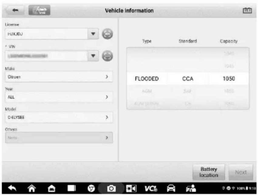
Figure 13-4 Sample Battery information Screen
Please refer to the table below for a list of buttons that may appear when accessing the functions:
Table 13-3 Top Toolbar Buttons
| Name | Button | Description |
| Battery Connection |  | The value on the icon indicates the real-time voltage of the tested battery. In the battery test, the button will turn green if the battery is good; otherwise, it will turn red. |
| Next |  | Tap to proceed. |
| Home |  | Returns to the MaxiSys Job Menu. |
| Back |  | Returns to the previous screen. |
| Exit |  | Returns to the Job Menu. |
Battery Test
- Follow the on-screen instructions. Check the boxes once all required tasks are completed, and tap Start Testing.
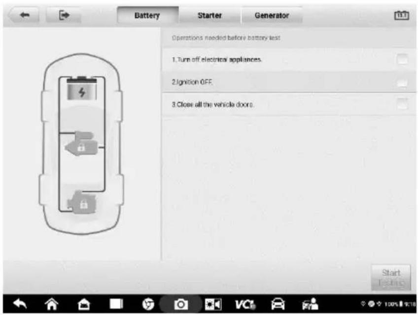
Figure 13-5 Sample Battery Screen
- Wait until the test is completed. The test results will be displayed on the tool.
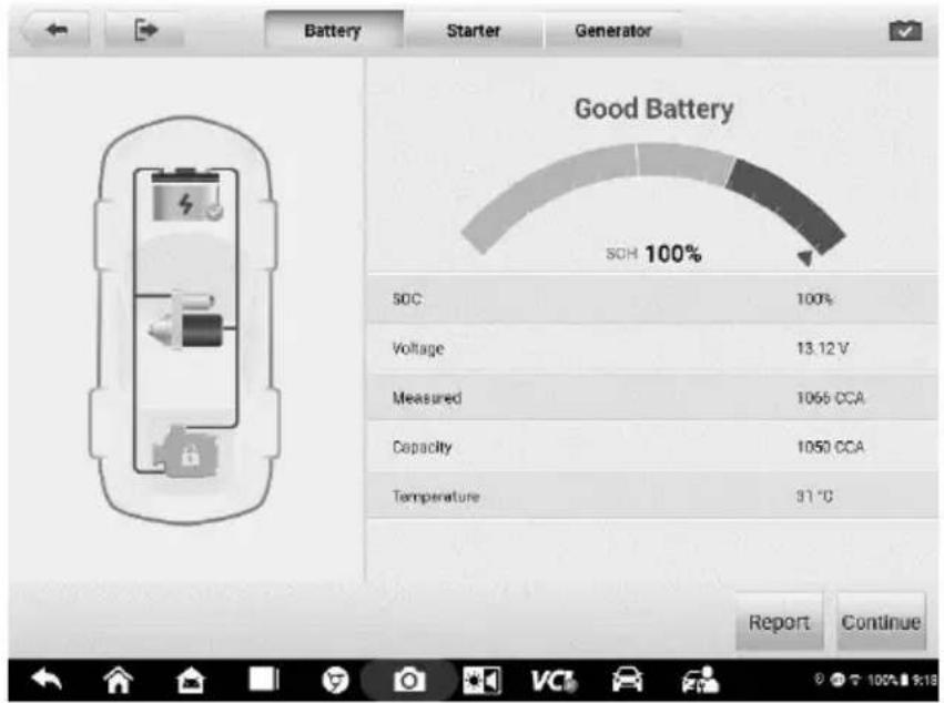
Figure 13-6 Sample Battery Test Results Screen
Battery Test Results
The battery test results include a color-coded results summary, a list of test data, and repair tips.
Table 13-4 Test Results
| Result | Repair Tip |
| Good Battery | Battery is good. |
| Good & Recharge | Battery is good but insufficiently charged. Recharge the battery. |
| Charge & Retest | Battery requires charge to determine its condition. |
| Bad Cell | Replace the battery. |
| Replace Battery | Replace the battery. |

NOTE
Please always complete the battery test before you proceed to the starter and generator tests.
Starter Test
Follow the on-screen instructions to complete the test. Start the engine and let it idle. The test results will appear as follows:
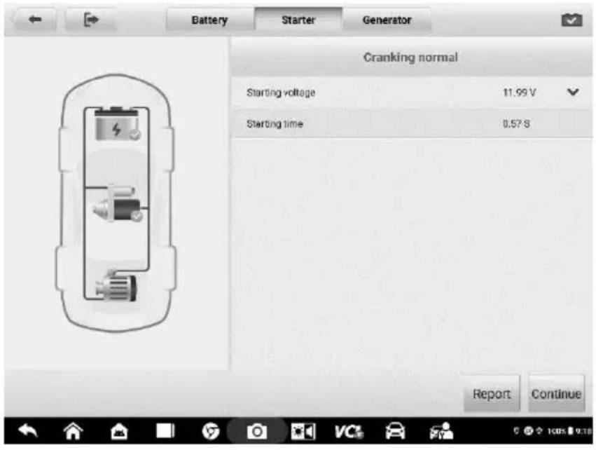
Figure 13-7 Sample Starter Test Result Screen
Table 13-5 Starter Test Results
| Result | Description |
| Cranking Normal | The starter is good. |
| Current Too Low | Low momentary discharge capacity. |
| Voltage Too Low | Low battery storage capacity. |
| Not Started | The starter is not detected for starting. |
Generator Test
Follow the on-screen instructions to complete the test. The test results will appear as follows:

Figure 13-8 Sample Generator Test Results Screen
Table 13-6 Generator Test Results
| Result | Description |
| Charging Normal | The generator is functioning normally. |
| Output Too Low | ● The belt linking the starter and the generator is loose;● The cable linking the starter and battery is loose or corroded. |
| Output Too High | ● The generator is not properly connected to the ground;● The voltage adjuster is broken and needs replacement. |
| Ripple Too Large | The commutation diode is broken. |
| No Output | ● The cable is loose;● Some vehicles with power management systems do not provide path for charging due to the sufficient load capacity of the battery;● The generator or the voltage adjuster is broken and needs replacement. |

NOTE
To measure the current, connect the current clamp. Tap the Settings button on the main menu to enter the application. Swipe the Current Clamp toggle to turn it ON.
Out-vehicle Test
Out-vehicle Test is used to test the conditions of batteries that are not connected to a vehicle. This function aims to check the health status of the battery only.
Test Procedure
To start the out-vehicle test
- Select Out-vehicle Test.
- Connect the tester clamps to the battery terminals.
- Select the appropriate battery type, rating standard, and CCA value. Tap Start Testing to start the test.
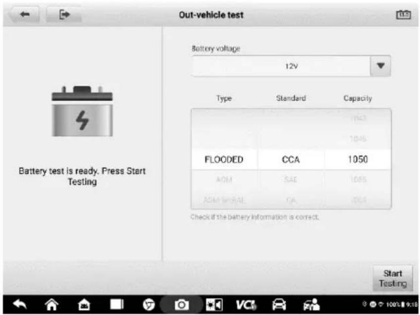
Figure 13-9 Sample Out-vehicle Test Screen
- The test results will display in a few seconds.
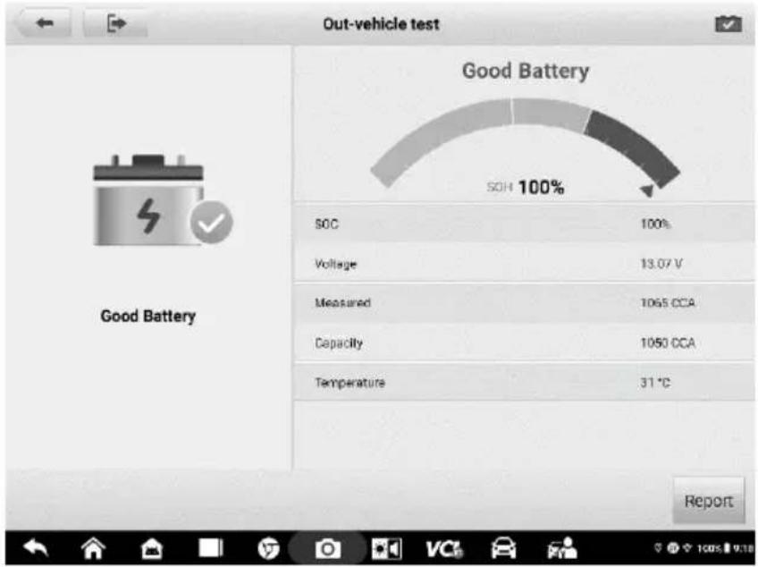
Figure 13-10 Sample Out-vehicle Test Results Screen
Test Results
Icons are color-coded to indicate status.
Table 13-7 Out-vehicle Test Results
| Result | Description |
| Good Battery | Battery meets required standards. |
| Good & Recharge | Battery is good, but low on charge. Fully charge the battery. Check for causes of low charge. |
| Charge & Retest | Battery requires charge to determine its condition. |
| Replace Battery | Battery fails to meet industry-accepted standards. |
| Bad Cell | Battery fails to meet industry-accepted standards. |
14 MaxiViewer
MaxiViewer allows you to search functions and the version information supported by our tools. There are two ways of searching, either by searching the tool and the vehicle or searching the functions.
To search by vehicle
- Tap the MaxiViewer application on the MaxiSys Job Menu. The MaxiViewer application screen appears.
- Tap the tool name on the top-left to drop down the tool list and tap the one you want to search.
- Tap the vehicle brand, model, and year you want to search.

Figure 14-1 Sample MaxiViewer Screen 1
- All functions supported by the selected tool for the selected vehicle are displayed with vehicle's system, type, function, sub function, and version.
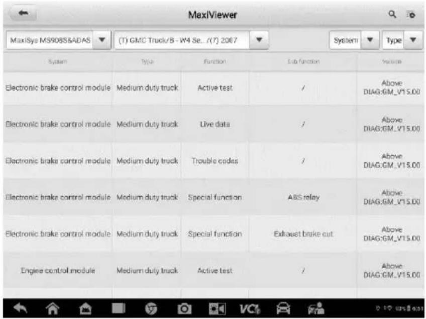
Figure 14-2 Sample MaxiViewer Screen 2
To search by the functions
- Tap the MaxiViewer application on the MaxiSys Job Menu. The MaxiViewer application screen displays.
- Tap the tool name on the top-left to drop down the tool list, and tap the one you want to search.
- Enter the function you want to search in the top-right search box. The screen will display all vehicles that support this function, along with information such as the vehicles' year, system, capacity, type, function, sub-function, and version.
NOTE
Partial search is supported: type in any part of the function-related keywords to find all available information.
15 Quick Link
The Quick Link application provides you with convenient access to Autel's official website and many other well-known sites in the automotive service industry to provide technical help, knowledgebase, forums, training, and expertise consultations.

Figure 15-1 Sample Quick Link Screen
To open a quick link
- Tap Quick Link on the MaxiSys Job Menu. The Quick Link application screen appears.
- Select a website thumbnail from the main section. The browser is launched and the selected website is opened.
- Now you can start exploring the website.
16 User Feedback
The User Feedback feature allows you to submit questions related to this product.

Figure 16-1 Sample User Feedback Screen
To send new user feedback
- Register the product online. See Product Registration for detailed information.
- Tap User Feedback on the MaxiSys Job Menu. The device information is automatically synchronized with the online account.
- Enter your telephone number/email address, feedback type, theme, and problem description. You can also attach a voice recording, photo, photo album, screen captures, image or PDF files to the form. To help us resolve the issue more efficiently, we recommend you complete the form with as detailed as possible.
- Tap Submit to send the completed form to Autel's online service center. The submitted feedback will be carefully read and handled by our service personnel.
17 MaxiScope
The MaxiScope application configures the MaxiSys Diagnostics Device to operate as an automotive oscilloscope when used in combination with the MaxiScope module. This function provides all the features needed for performing electrical and electronic circuit tests as well as monitoring signal activities on any modern vehicles, which shows you what is really going on with a vehicle's electrical system.
Please download the latest user manual for Autel MaxiScope device from www.autel.com > Specialty Tools > MORE PRODUCTS > MaxiScope MP408 > Downloads.
18 MaxiVideo
The MaxiVideo application configures the MaxiSys Diagnostics Device to operate as a digital video scope by simply connecting the tablet to a MaxiVideo Camera. This function allows you to examine difficult-to-reach areas normally hidden from sight, with the ability to record digital still images and videos, which offers you an economical solution to inspect machinery, facilities, and infrastructure in a safe and quick way.

WARNINGS:
Follow these instructions to reduce the risk of injury from electric shock, entanglement and other causes and prevent tool damage.
- Do not place the image head and cable into anything or anywhere that may contain a live electric charge or moving parts, which increases the risk of electric shock or entanglement injuries.
- Do not use the image head cable to modify surroundings, clear pathways or clogged areas.
- When inspection is completed, carefully withdraw the imager head cable from the inspection area.
- The image head cable are waterproof to a depth of 3 m (10'), greater depths may cause leakage into the imager head cable and cause electric shock or damage the tool.
- The working temperature of the imager head is between 32 °F (0 °C) and 113 °F (45 °C).
Check-Ups:
√ FOR AUTOMOBILES: Ensure the automobile is not running during inspection. Metal and liquid under the hood may be hot. Don't get oil or gas on the imager head.
√ FOR PIPES: If you suspect a metal pipe could contain an electric charge, have a qualified electrician to check the pipe before using.
√ FOR WALLS: For inspecting the inside walls, be sure to shut off the circuit breaker to the whole house before using the tool.
√ WORK AREA: Ensure the work area has sufficient light.
Additional Accessories
The MaxiVideo Camera and its fittings are the additional accessories. Both sizes (8.5 mm and 5.5 mm) of the imager head are optional and available for purchase along with the standard MaxiSys tool kit.
MaxiVideo Camera

Figure 18-1 MaxiVideo Camera
- Removable Imager Head Cable — connects to the tool when performing digital inspections for image and video viewing.
- Handgrip — ergonomically designed handle for comfortable grips and agile operation.
- USB Cable — connects the MaxiVideo Camera to MaxiSys tablet.
Imager Head Accessories

Figure 18-2 8.5 mm Imager Head Accessories
-
Mirror — helps to look around corners and see the unreachable areas.
-
Hook — unclogs obstacles and picks up wires in the pipes or confined areas.
-
Magnet — picks up small metal objects, such as dropped rings or screws.

Figure 18-3 5.5 mm Imager Head Accessories
-
Mirror — helps to look around corners and see the unreachable areas.
-
Magnet — picks up small metal objects, such as dropped rings or screws.
Accessory Assembly
For 8.5 mm Imager Head
The three accessories, including the Magnet, Hook, and Mirror, can be attached to the Imager Head with the same manner described below:
- Hold the accessory and the imager head.

natural_image
Diagram of a cylindrical device with an arrow indicating assembly or transformation (no text or symbols)- Slip the end of the accessory over the imager head and then fix the accessory.
For 5.5 mm Imager Head
The two accessories, including the Magnet and Mirror, can be attached to the Imager Head with the same manner described below:

natural_image
Simple line drawing of a cylindrical object with a pointed tip and arrow indicating motion (no text or symbols)- Hold the accessory and the imager head.

natural_image
Diagram of a cylindrical mechanical component with a rotating arrow indicating rotation (no text or symbols)- Screw the thread part of the accessory over the imager head to fix the accessory.

natural_image
Simple line drawing of a cylindrical object with a pointer and spark, no text or symbols present.Technical Specifications
Table 18-1 Specifications
| Item | Description |
| Optimal Viewing Distance | ● 0.79" to 2.36" (2 to 6 cm) with 8.5 mm diameter imager head● 0.79" to 2.36" (2 to 6 cm) with 5.5 mm diameter imager head |
| Image Capture | ● JPG images (640 x 480)● AVI videos (320 x 240) |
| Operating Temperature | ● Main Unit: 0 °C to 55 °C(ambient)● Cable: -10 °C to 70 °C |
| Storage Temperature | -20 °C to 75 °C(ambient) |
| Waterproof | Imager head and cable to 1 m |
| Weight | ● 0.3 kg with 8.5 mm diameter imager head● 0.2 kg with 5.5 mm diameter imager head |
Operations
Before performing the MaxiVideo application, the Imager Head Cable must be connected to the tablet through the USB port. Install the correct imager head accessories for use in the appropriate application.

NOTE
When in operation, the imager head cable can be bent into a certain shape. This may help you operate the cable into confined areas.
To take pictures using the MaxiVideo application
- Connect the Imager Head Cable to the USB port on the top side of the tablet.
- If not already done, power up the tablet.
- Tap the MaxiVideo application on the MaxiSys Job Menu. The MaxiVideo application interface displays, showing a camera operating screen. The default camera is now the Imager head.
- Select the Camera icon at the lower right corner to take photos.
- Focus the image to be captured in the viewfinder by adjusting and properly locating the imager head cable.
- Tap the blue ring on the operating screen. The viewfinder now displays the captured picture and auto-saves the taken photo.
- Tap the thumbnail image on the top right corner of the screen to view the stored image, slide the screen left and right to view the images one by one.
- Tap on the selected image and the edit toolbar instantly displays.
- Tap the appropriate button to share, delete, or edit the image.
- Tap the Back or Home button on the Navigation bar at the bottom of the screen to exit the MaxiVideo application.
To record a video using the MaxiVideo application
- Connect the Imager Head Cable to the USB port on the top side of the tablet.
-
If not already done, power up the tablet.
-
Tap the MaxiVideo application on the MaxiSys Job Menu. The MaxiVideo application interface displays, showing a camera operating screen. The default camera is now the Imager head.
- Select the Video icon at the lower right corner to record a video.
- Properly locate the imager head cable to focus the inspection scene for recording.
- Tap the red ring on the operating screen to start recording.
- Tap the red circle again to stop recording. The recorded video is automatically saved to the system Gallery.
- Tap the thumbnail image on the top right corner to review the recorded video.
- Tap the Play button to play the video.
- Tap on the selected video and the edit toolbar instantly displays.
- Tap the appropriate button to share, delete, or edit the video.
- Tap the Back or Home button on the Navigation bar at the bottom of the screen to exit the Digital Inspection application.
To configure various settings for the work mode of the imager head
- Tap button at the bottom edge of the circle.
- Select each item to make appropriate adjustments.
For more tips and detailed information about the camera application, please refer to associated Android documentations.
19 Maintenance and Service
To ensure that the tablet and the combined VCI unit perform at their optimum level, we advise that the product maintenance instructions covered in this section is read and followed.
Maintenance Instructions
The following shows instructions on how to maintain your devices, together with precautions to take.
- Use a soft cloth and alcohol or a mild window cleaner to clean the touch screen of the tablet.
- Do not use any abrasive cleansers, detergent, or automotive chemicals to the tablet.
- Maintain the devices in dry conditions and keep them within normal operating temperatures.
- Dry your hands before using the tablet. The touch screen of the tablet may not work if the touch screen is moist, or if you tap the touch screen with wet hands.
- Do not store the devices in humid, dusty or dirty areas.
- Check the housing, wiring, and connectors for dirt and damage before and after each use.
- At the end of each work day, wipe the device housing, wiring, and connectors clean with a damp cloth.
- Do not attempt to disassemble your tablet or the VCI unit.
- Do not drop or cause severe impact to the devices.
- Use only authorized battery chargers and accessories. Any malfunction or damage caused by the use of unauthorized battery charger and accessories will void the limited product warranty.
- Ensure that the battery charger does not come in contact with conductive objects.
- Do not use the tablet beside microwave ovens, cordless phones and some medical or scientific instruments to prevent signal interference.
Troubleshooting Checklist
A. When the tablet does not work properly:
● Make sure the tablet has been registered online.
● Make sure the system software and diagnostic application software are properly
updated.
● Make sure the tablet is connected to the Internet.
- Check all cables, connections, and indicators to see if the signal is being received.
B. When battery life is shorter than usual:
- This may happen when you are in an area with low signal strength. Turn off your device if is not in use.
C. When you cannot turn on the tablet:
● Make sure the tablet is connected to a power source or the battery is charged.
D. When you are unable to charge the tablet:
- Your charger maybe out of order. Contact your nearest dealer.
- You may be attempting to use the device in an overly hot/cold temperature. Charge the device in a cooler or warmer area.
- Your device may have not been connected to the charger properly. Check the connector.

NOTE
If the problems persist, please contact Autel's technical support personnel or your local selling agent.
About Battery Usage
Your tablet is powered by a built-in Lithium-ion Polymer battery. This means that, unlike other forms of battery technology, you can recharge your battery while some charge remains without reducing your tablet's autonomy due to the “battery memory effect” inherent in those technologies.

DANGER
The built-in Lithium-ion Polymer battery is factory replaceable only; incorrect replacement or tampering with the battery pack may cause an explosion.
- Do not use a damaged battery charger.
- Do not disassemble or open crush, bend or deform, puncture or shred.
- Do not modify or remanufacture, attempt to insert foreign objects into the battery, expose to fire, explosion or another hazard.
- Use only the included charger and USB cables. Failure to use Autel-authorized charger and/or USB cables, may result in device malfunction or failure.
- Use of an unqualified battery or charger may present a risk of fire, explosion, leakage, or another hazard.
-
Avoid dropping the tablet. If the tablet is dropped, especially on a hard surface, and the user suspects damage, take it to a service center for inspection.
-
The closer you are to your network's wireless router, the longer your tablet usage time because less battery power is consumed for the connection.
● The battery recharging time varies depending on the remaining battery capacity.
● Battery life inevitably shortens over time. - Since overcharging may shorten battery life, remove the tablet from its charger once it is fully charged. Unplug the charger, once charging is complete.
- Leaving the tablet in hot or cold places, especially inside a car in summer or winter, may reduce the capacity and life of the battery. Always keep the battery within normal temperatures.
Service Procedures
This section introduces information for technical support, repair service, and application for replacement or optional parts.
Technical Support
If you have any question or problem on the operation of the product, please contact us.
AUTEL NORTH AMERICA
● Phone: 855-AUTEL-US (855-288-3587) (Monday-Friday 9am-6pm Eastern Time)
Website: www.autel.com
- Email: ussupport@autel.com
- Address: 36 Harbor Park Drive, Port Washington, New York, USA 11050
AUTEL EUROPE
● Phone: 0049 (0) 6103-2000520 (Monday-Friday, 9:00AM-6:00PM Berlin Time)
Website: www.autel.eu
- Email: sales.eu@autel.com, support.eu@autel.com
● Address: Landsberger Str. 408, 81241 München, Germany
AUTEL CHINA HQ
● Phone: 0086-755-86147779
Website: www.auteltech.cn
- Email: support@autel.com
- Address: 7th, 8th and 10th Floor, Building B1, Zhiyuan, Xueyuan Road, Xili, Nanshan, Shenzhen, 518055, China
AUTEL LATIN AMERICA
Website: www.autel.com
- Email: sales.latin@autel.com, latsupport02@autel.com
- Address: Avenida Americas 1905, 6B, Colonia Aldrete, Guadalajara, Jalisco, Mexico
AUTEL APAC
● Phone: +045 5948465
Website: www.autel.com/jp/
- Email: sales.jp@autel.com; support.jp@autel.com
- Address: 719, Nissou Building, 3-7-18, Shinyokohama, Kouhoku, Yokohama, Kanagawa, Japan 222-0033
AUTEL IMEA DMCC
● Phone: +971 585 002709
Website: www.autel.com
- Email: sales.imea@autel.com; imea-support@autel.com
- Address: 906-17, Preatoni Tower (Cluster L), Jumeirah Lakes Tower, DMCC, Dubai, UAE
For technical assistance in other markets, please contact your local selling agent.
Repair Service
If it becomes necessary to return your device for repair, please download the repair service form from www.autel.com, and fill in the form. The following information must be included:
- Contact name
- Return address
- Telephone number
- Product name
- Complete description of the problem
● Proof-of-purchase for warranty repairs - Preferred method of payment for non-warranty repairs

NOTE
For non-warranty repairs, payment can be made with Visa, Master Card, or with approved credit terms.
Send the device to your local agent, or to the below address:
8th Floor, Building B1, Zhiyuan, Xueyuan Road, Xili, Nanshan, Shenzhen, 518055, China
Other Services
You can purchase the optional accessories directly from Autel's authorized tool suppliers, and/or your local distributor or agent.
Your purchase order should include the following information:
- Contact information
● Product or part name - Item description
● Purchase quantity
20
Compliance Information
FCC Compliance
FCC ID: WQ8-MS908S2122
This equipment has been tested and found to comply with the limits for a Class B digital device, pursuant to Part 15 of the FCC Rules. These limits are designed to provide reasonable protection against harmful interference in a residential installation. This equipment generates uses and can radiate radio frequency energy and, if not installed and used in accordance with the instructions, may cause harmful interference to radio communications. However, there is no guarantee that interference will not occur in a particular installation. If this equipment does cause harmful interference to radio or television reception, which can be determined by turning the equipment off and on, the user is encouraged to try to correct the interference by one or more of the following measures:
● Reorient or relocate the receiving antenna.
- Increase the separation between the equipment and receiver.
- Consult the dealer or an experienced radio/TV technician for help.
This device complies with part 15 of the FCC Rules. Operation is subject to the following two conditions:
(1) This device may not cause harmful interference, and
(2) this device must accept any interference received, including interference that may cause undesired operation.
Changes or modifications not expressly approved by the party responsible for compliance could void the user's authority to operate the equipment.
SAR:
The radiated output power of this device is below the FCC radio frequency exposure limits. Nevertheless, the device should be used in such a manner that the potential for human contact is minimized during normal operation.
The exposure standard for wireless devices employs a unit of measurement known as the Specific Absorption Rate, or SAR. The SAR limit set by the FCC is 1.6 W/Kg. Tests for SAR are conducted using standard operating positions accepted by the FCC with the device transmitting at its highest certified power level in all tested frequency bands. Although the SAR is determined at the highest certified power level, the actual SAR level of the device while operating can be well below the maximum value. This is because the device is designed to operate at multiple power levels so as to use only the power
required to reach the network. To avoid the possibility of exceeding the FCC radio frequency exposure limits, human proximity to antenna should be minimized.
CE Compliance
RED Directive 2014/53/EU.
RoHS Compliance
This device is declared to be in compliance with the European RoHS Directive 2011/65/EU.
21 Warranty
12-Month Limited Warranty
Autel Intelligent Technology Corp., Ltd. (the Company) warrants to the original retail purchaser of this MaxiSys Diagnostics Device that should this product or any part thereof during normal usage and under normal conditions be proven defective in material or workmanship that results in product failure within twelve (12) months period from the date of purchase, such defect(s) will be repaired, or replaced (with new or rebuilt parts) with Proof of Purchase, at the Company's option, without charge for parts or labor directly related to the defect(s).
The Company shall not be liable for any incidental or consequential damages arising from the use, misuse, or mounting of the device. Some states do not allow limitation on how long an implied warranty lasts, so the above limitations may not apply to you.
This warranty does not apply to:
a) Products subjected to abnormal use or conditions, accident, mishandling, neglect, unauthorized alteration, misuse, improper installation or repair or improper storage;
b) Products whose mechanical serial number or electronic serial number has been removed, altered or defaced;
c) Damage from exposure to excessive temperatures or extreme environmental conditions;
d) Damage resulting from connection to, or use of any accessory or other product not approved or authorized by the Company;
e) Defects in appearance, cosmetic, decorative or structural items such as framing and non-operative parts.
f) Products damaged from external causes such as fire, dirt, sand, battery leakage, blown fuse, theft or improper usage of any electrical source.
IMPORTANT
All contents of the product may be deleted during the process of repair. You should create a back-up copy of any contents of your product before delivering the product for warranty service.
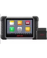

- Copyright Information
- Disclaimer of Warranties and Limitation of Liabilities
- IMPORTANT
- For Services and Support:
- Safety Information
- Safety Messages
- DANGER
- WARNING
- Safety Instructions
- Do Not Turn the Volume Up Too Loud When Using Headphones
- SAFETY WARNINGS:
- CONTENTS
- Using This Manual
- Conventions
- Bold Text
- Notes and Important Messages
- NOTE
- Hyperlink
- Illustrations
- Procedures
- To use the camera:
- General Introduction
- MaxiSys Tablet
- Power Sources
- Vehicle Power
- Technical Specifications
- VCI — Wireless Diagnostic Interface
- Function Descriptions
- Communication
- Accessories Kit
- Main Cable
- OBDI Adapters (Optional)
- Other Accessories
- Standard 2.0 USB Cable
- Mini USB Cable
- AC/DC External Power Adapter
- Auxiliary Power Outlet Adapter
- Spare Fuse x2
- Clamp Cable
- USB to Ethernet Adapter
- Getting Started
- Power Up
- Application Buttons
- Page Control and Navigation Buttons
- System Status Icons
- Power Down
- To power down the MaxiSys tablet:
- Reboot System
- Diagnostics
- Establish Vehicle Communication
- Vehicle Connection
- To connect to an OBDII vehicle
- Non-OBDII Vehicle Connection
- To connect to a Non-OBDII Vehicle
- To connect the auxiliary power outlet adapter
- VCI Connection
- Bluetooth Connection
- To pair up the tablet with the VCI via Bluetooth
- USB Cable Connection
- No Communication Message
- Vehicle Menu Layout
- Automobile Manufacturer Buttons
- Vehicle Identification
- Auto VIN Scan
- To perform an Auto VIN Scan
- Manual VIN Input
- To perform Manual VIN Input
- Scan VIN/License
- Manual Vehicle Selection
- Step-by-step Vehicle Selection
- Alternative Vehicle Identification
- Navigation
- Diagnostics Screen Layout
- Diagnostics Toolbar
- To print data in Diagnostics
- To submit Data Logging reports in Diagnostics
- Current Directory Path
- Status Information Bar
- Main Section
- Function Buttons
- Screen Messages
- Confirmation Messages
- Warning Messages
- Error Messages
- Making Selections
- Main Menu
- Diagnosis
- Navigation Bar
- Control Unit
- To perform a diagnostic function
- ECU Information
- Trouble Codes
- Read Codes
- Figure 4-12 Sample Read Codes Screen
- Erase Codes
- To erase codes
- Live Data
- Display Mode
- To edit the waveform color and line thickness in a data graph
- Trigger Settings
- To set a trigger
- To merge selected data graphs
- To set live data record duration
- Active Test
- Special Functions
- Generic OBDII Operations
- General Procedure
- To access the OBDII/EOBD diagnostics functions
- DTC & FFD
- - Stored Codes
- - Pending Codes
- - Freeze Frame
- - Erase Codes
- I/M Readiness
- O2 Sensor Monitor
- On-Board Monitor
- Component Test
- Vehicle Information
- Vehicle Status
- Exit Diagnostics
- To exit the Diagnostics application
- Service
- Oil Reset Service
- Electric Parking Brake (EPB) Service
- EPB Safety
- Tire Pressure Monitoring System (TPMS) Service
- Battery Management System (BMS) Service
- Steering Angle Sensor (SAS) Service
- Diesel Particle Filter (DPF) Service
- Immobilizer (IMMO) Service
- 6
- ADAS
- Data Manager
- Vehicle History
- Test Records
- To edit a previous Test Record
- Workshop Information
- To edit the Workshop information sheet
- Customer
- To create a customer account
- To edit a customer account
- To delete a customer account
- Image
- To edit/delete image(s)
- PDF Files
- Review Data
- Uninstall Apps
- Data Logging
- Settings
- Operations
- Unit
- To adjust the unit setting
- Language
- To adjust the language setting
- Printing Settings
- To setup a printer connection
- Printing Operations
- To install the MaxiSys Printer driver
- To print from a computer
- Auto Update
- ADAS Settings
- To adjust the ADAS settings
- Vehicle List
- To adjust the vehicle list setting
- System Settings
- About
- To check the MaxiSys product information in About
- Update
- To update the software
- VCI Manager
- VCI Connection via Bluetooth
- To pair the VCI with the tablet via Bluetooth
- BAS Connection via Bluetooth
- To pair the BT506 series tester with the tablet
- VCI Update
- To update the VCI
- BAS Update
- To update the MaxiBAS BT506
- Remote Desktop
- Figure 11-1 Sample Remote Desktop Screen
- To receive remote support from a partner
- Support
- Product Registration
- To register the diagnostic device
- Support Screen Layout
- My Account
- Personal Info
- Update Info
- Service Info
- Training
- To make a reply in a Data Logging session
- FAQ
- Battery Test
- MaxiBAS BT506 Tester
- Test Preparation
- Inspect the Battery
- Connect the Battery Tester
- To pair the BT506 with the MaxiSys tablet
- To connect to a battery
- In-vehicle Test
- ▶ Confirm Vehicle Information
- Battery Test
- Battery Test Results
- Starter Test
- Generator Test
- Out-vehicle Test
- Test Procedure
- To start the out-vehicle test
- Test Results
- MaxiViewer
- To search by vehicle
- To search by the functions
- Quick Link
- To open a quick link
- User Feedback
- To send new user feedback
- MaxiScope
- MaxiVideo
- WARNINGS:
- Check-Ups:
- Additional Accessories
- MaxiVideo Camera
- Imager Head Accessories
- Accessory Assembly
- To take pictures using the MaxiVideo application
- To record a video using the MaxiVideo application
- To configure various settings for the work mode of the imager head
- Maintenance and Service
- Maintenance Instructions
- Troubleshooting Checklist
- About Battery Usage
- Service Procedures
- Technical Support
- AUTEL NORTH AMERICA
- AUTEL EUROPE
- AUTEL CHINA HQ
- AUTEL LATIN AMERICA
- AUTEL APAC
- AUTEL IMEA DMCC
- Repair Service
- Other Services
- 20
- Compliance Information
- FCC Compliance
- FCC ID: WQ8-MS908S2122
- SAR:
- CE Compliance
- RoHS Compliance
- Warranty
- 12-Month Limited Warranty
- This warranty does not apply to:
Brand : Autel
Model : MaxiSYS MS908S II
Category : Car diagnostics