
AP5202 - Network switch APC - Free user manual and instructions
Find the device manual for free AP5202 APC in PDF.


| Type | Network Switch |
| Model | AP5202 |
| Ports | 5 x 10/100 Mbps Ethernet |
| Standards | IEEE 802.3, 802.3u, 802.3x |
| Switching Capacity | 1 Gbps |
| MAC Address Table | 1K entries |
| Dimensions (WxDxH) | 5.0 x 3.5 x 1.5 inches |
| Weight | 0.5 lbs |
| Power Input | 5V DC, 1A (external adapter) |
| Power Consumption | 2.5W maximum |
| LED Indicators | Power, Link/Activity per port |
| Mounting | Desktop or wall-mountable |
| Operating Temperature | 0°C to 40°C |
| Storage Temperature | -20°C to 70°C |
| Humidity | 10% to 90% non-condensing |
| Enclosure | Metal chassis |
| Cooling | Fanless |
| Certifications | FCC, CE, RoHS |
| Warranty | 2 years |
Frequently Asked Questions - AP5202 APC
User questions about AP5202 APC
0 question about this device. Answer the ones you know or ask your own.
Ask a new question about this device
Download the instructions for your Network switch in PDF format for free! Find your manual AP5202 - APC and take your electronic device back in hand. On this page are published all the documents necessary for the use of your device. AP5202 by APC.
USER MANUAL AP5202 APC
Installation and Quick Start
Coaxial Analog KVM Switch Coaxial Analog KVM Console Extender
AP5201
AP5202
AP5203
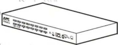
This manual is available in English on the enclosed CD.
Coaxial Analog KVM Switch 1
Product Description and Inventory....1
Overview.... 1
Inventory 1
Hardware requirements ....1
Additional documentation .... 3
Front panel of Coaxial Analog KVM Switch
(AP5202 shown) 4
Rear panel of Coaxial Analog KVM Switch
(AP5202 shown) 6
How to Mount the Coaxial Analog KVM Switch....7
Mounting options. 7
How to Install a Single Coaxial Analog KVM Switch. 8
Pre-installation 8
Single-station installation 8
How to Install Multiple Coaxial Analog KVM Switches ..... 9
Pre-installation 9
Serial connection 9
How to Apply Power....11
Turning off and restarting the Coaxial
Analog KVM Switch 11
Operation—Coaxial Analog KVM Switch ..... 12
Hot Key mode 12
Selecting the active port 12
Hot Key summary table .....13
On Screen Display (OSD) operation .....14
OSD navigation 14
OSD functions .....15
Specifications 16
Coaxial Analog KVM Console Extender 17
Product Description and Inventory....17
Overview 17
Inventory 17
Hardware requirements .....17
Front view of Coaxial Analog KVM
Console Extender 18
How to Install the Coaxial Analog KVM Console Extender . . . 19
Pre-installation 19
Installation.... 19
Operation—Coaxial Analog KVM Console Extender ..... 20
Specifications 21
Product Description and Inventory
Overview
Use the Coaxial Analog KVM Switch to control multiple servers with only one monitor, keyboard, and mouse. Control up to 256 servers with a daisy chain of 32 AP5201 Coaxial Analog KVM Switches, or control up to 512 servers with a daisy chain of 32 AP5202 Coaxial Analog KVM Switches.
Inventory
Quantity Item
| 1 | Coaxial Analog KVM SwitchAP5201 (8 ports) orAP5202 (16 ports) |
| 1 | Configuration cable |
| 1 | L5-15 to IEC power cable |
| 2 | Mounting brackets for a 19-inch enclosure |
| 1 | Installation and Quick Start manual |
| 1 | Coaxial Analog KVM Switch Utility CD |
| 1 | Warranty card |
Hardware requirements
Console. To use the Coaxial Analog KVM Switch, you need the following equipment:
- VGA, SVGA, or Multisync monitor capable of the highest resolution that you plan to use on any server in the installation
- PS/2-style mouse
- PS/2-style keyboard
Server. To access the Coaxial Analog KVM Switch, your server requires the following:
• VGA, SVGA, or Multisync card
- 6-pin mini-DIN (PS/2-style) mouse port

Note: The Coaxial Analog KVM Switch does not support serial mice. You cannot use serial-to-PS/2 adapters with the cables.
- Keyboard port:
- 6-pin mini-DIN (PS/2-style) keyboard port with +5 Vdc on pin 4 and ground on pin 3, or
- 5-pin DIN (AT-style) keyboard port with +5 Vdc on pin 5 and ground on pin 4

Note: If your server uses an AT-style keyboard socket, purchase a PS/2-to-AT keyboard adapter to plug the cable into the keyboard port on the server.
Cable. To use the Coaxial Analog KVM Switch, connect the proper cables to the switch. APC offers the following cable types for your switch:
APC Part Number Cable Type Cable Length
| AP5264 PS/2 cable 3 ft (0.9 m) |
| AP5250 PS/2 cable 6 ft (1.8 m) |
| AP5254 PS/2 cable 12 ft (3.6 m) |
| AP5258 PS/2 cable 25 ft (7.6 m) |
| AP5253 USB cable 6 ft (1.8 m) |
| AP5257 USB cable 12 ft (3.6 m) |
| AP5261 USB cable 25 ft (7.6 m) |
| AP5251 SUN (13W3) cable 6 ft (1.8 m) |
| AP5255 SUN (13W3) cable 12 ft (3.6 m) |
| AP5259 SUN (13W3) cable 25 ft (7.6 m) |
| AP5252 SUN (VGA) cable 6 ft (1.8 m) |
| AP5256 SUN (VGA) cable 12 ft (3.6 m) |
| AP5260 SUN (VGA) cable 25 ft (7.6 m) |
| AP5262 Daisy chain cable for serial connection 2 ft (0.6 m) |
| AP5263 Daisy chain cable for serial connection 6 ft (1.8 m) |

Warning: Incorrect installation can cause improper functioning of the device or damage to hardware. Substandard cables can produce toxic fumes if a fire occurs.
Additional documentation
The Coaxial Analog KVM Switch User's Guide is available on the supplied CD and on the APC Web site (www.apc.com). The User's Guide contains additional information about the following topics related to the Coaxial Analog KVM Switch:
- On-Screen Display (OSD) and the menu-driven interface
- User accounts
- Hot-plugging
- Hot Key operation
Front panel of Coaxial Analog KVM Switch (AP5202 shown)
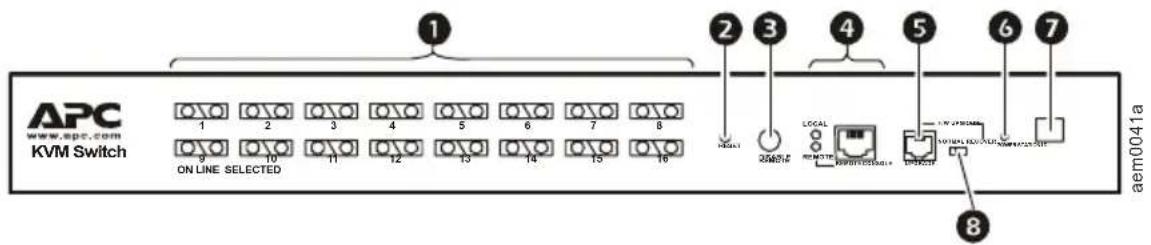
Item Description
| 1 | Port LEDs | Each port has a left (Online) and right (Selected) LED pair that provides status information about a corresponding server port.A GREEN Online LED indicates the corresponding attached server port is operating correctly.An ORANGE Selected LED indicates the corresponding attached server has the KVM focus. Under normal conditions, the LED is steady. When accessing its port under Auto Scan Mode, the LED flashes.Each time the Coaxial Analog KVM Switch begins to provide power, it performs a self-test. The Online LED and then the Selected LED blink once during the self-test. |
| 2 | Reset switch Allows you to perform a system reset by pressing the recessed Reset switch with a thin object (such as the end of a paper clip or ballpoint pcn). | |
| 3 | Disable Remote button Enables or disables remote access to the console. | |
| 4 | Remote console To use a remote console, plug a CAT-5 cable (not included) into the RJ-45 connector. When both a local and remote console are present, both can access the Analog KVM Switch (but not simultaneously).Push the Disable Remote button to toggle between “Remote access allowed” and “Remote access disabled.”When the remote console is accessing the switch, you can view input data through the local console, but can only make changes through the remote console. When the local console is accessing the switch, you can view input data through the remote console, but can only make changes through the local console.The Local and Remote LEDs indicate which console is currently in use. When a remote extension unit is attached and is receiving power, the two LEDs alternately light when no one is accessing either console. | |
| 5 | Upgrade port The firmware upgrade cable plugs into the RJ-11 connector and transfers firmware upgrade data from the administrator's server to the Coaxial Analog KVM Switch. | |
Item Description
| 6 | Power LED Indicates that the Coaxial Analog KVM Switch is receiving power. | |
| 7 | Station ID LED Displays the two-digit station number of the Coaxial Analog KVM Switch. The station number indicates the Analog KVM Switch's position in the daisy-chain sequence. | |
| 8 | Firmware upgrade reset switch | The Reset switch is in the NORMAL position during normal operation or while performing a firmware upgrade. If the firmware upgrade does not succeed:Slide the Reset switch to the RECOVER position.Remove and then restore power to the Coaxial Analog KVM Switch.Slide the Reset switch back to the NORMAL position.Turn the Coaxial Analog KVM Switch off and then on. |
Rear panel of Coaxial Analog KVM Switch (AP5202 shown)
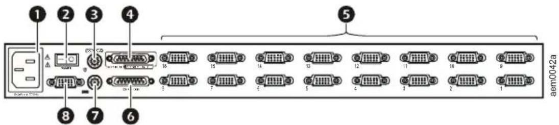
Item Description
① Power inlet 3-pin, AC power inlet.
2 Power switch Rocker-style switch for turning the Coaxial Analog KVM Switch on or off.
③ Mouse connector Connects to a PS/2-style mouse.
4 Chain In port Serially connects one Coaxial Analog KVM Switch to another. (This port is not used for the primary [Station 01] Coaxial Analog KVM Switch in a daisy-chain setup.)
5 Server connections Monitor connected servers; the AP5201 model can monitor up to eight, and the AP5202 model can monitor up to sixteen.
6 Chain Out port Serially connects one Coaxial Analog KVM Switch to another switch.
⑦ Keyboard connector Connects to a PS/2-style keyboard.
8 Monitor connector Connects to a VGA, SVGA, or Multisync monitor capable of the highest resolution that you plan to use on any server in the installation.
How to Mount the Coaxial Analog KVM Switch
Mounting options
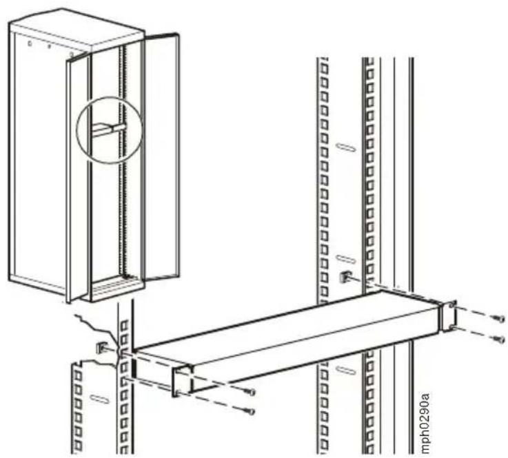
You can install the Coaxial Analog KVM Switch in the front or the rear of the rack or enclosure. To mount the Coaxial Analog KVM Switch horizontally in a NetShelter ^® or any other standard EIA-310 rack or enclosure:
-
Attach the mounting brackets to the front or rear of the Coaxial Analog KVM Switch, using flat-head screws (provided).
-
Insert cage nuts (provided with the NetShelter enclosure) on the vertical mounting rails above a number at the top of a U-space in your enclosure and below the same number at the bottom of the U-space.
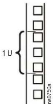
- Align the mounting holes on the brackets with the cage nuts you installed in step 2, and insert four mounting screws (provided with the rack) to secure the brackets to the enclosure.
natural_image
Technical line drawing of a wall-mounted cabinet and shelf assembly (no text or symbols)How to Install a Single Coaxial Analog KVM Switch
Pre-installation
Turn off power to all devices that you plan to connect. To prevent damage to your equipment because of static-electric discharge, ground all devices involved in the installation.

Warning: For safety and grounding instructions, consult your device manuals or contact the customer support department of the device manufacturer.
Single-station installation
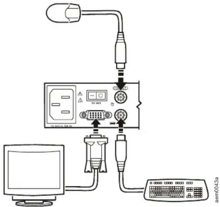
To install a single-station system, in which no additional Coaxial Analog KVM Switches are serially connected to the first Switch:
- Plug your keyboard, mouse, and monitor into the correct ports on the rear of the Coaxial Analog KVM Switch.
flowchart
graph TD
    A["Computer"] --> B["Power Bank"]
    B --> C["Router"]
    C --> D["PC"]
    D --> E["Monitor"]
    E --> F["Control Panel"]
    style A fill:#f9f,stroke:#333
    style B fill:#ccf,stroke:#333
    style C fill:#cfc,stroke:#333
    style D fill:#fcc,stroke:#333
    style E fill:#cff,stroke:#333
    style F fill:#ffc,stroke:#333
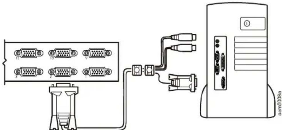
- For each server that you are connecting to the Coaxial Analog KVM Switch, use a custom cable set (see “Cable” on page 2) to connect any available server port on the rear of the Coaxial Analog KVM Switch to the Keyboard, Video, and Mouse ports of the server.
-
Plug the power cable into the port marked Power on the rear of the Coaxial Analog KVM Switch, and then plug the power cable into an AC power source.
-
Apply power to the servers.
How to Install Multiple Coaxial Analog KVM Switches
Pre-installation
Turn off power to all devices that you plan to connect. To prevent damage to your equipment because of static-electric discharge, ground all devices involved in the installation.

Warning: Consult your device manuals or contact the manufacturer's customer support department for safety and grounding instructions.
Serial connection
To control additional servers from a single console, you can connect up to 31 Coaxial Analog KVM Switches serially (in a daisy-chain setup) to the first Coaxial Analog KVM Switch. Control up to 256 servers with a daisy chain of 32 AP5201 Coaxial Analog KVM Switches, or control up to 512 servers with a daisy chain of 32 AP5202 Coaxial Analog KVM Switches.
-
Turn off power to all devices that you plan to connect.
-
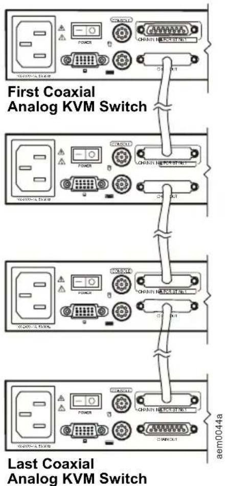
Use a custom cable set (see “Cable” on page 2) to connect the Coaxial Analog KVM Switches. Connect the Chain Out port of the first Coaxial Analog KVM Switch to the Chain In port of the second Coaxial Analog KVM Switch, connect the Chain Out port of the second Coaxial Analog KVM Switch to the Chain In port of the third Coaxial Analog KVM Switch, etc.

Note: Do not use the Chain In port of the first Coaxial Analog KVM Switch. Chain In ports are only used on Coaxial Analog KVM Switches that have a station number of 2 or higher.
Chain In ports are used to connect to the parent Coaxial Analog KVM Switch, which has a lower station ID number.
Do not use the Chain Out port of the last Coaxial Analog KVM Switch.
The following figure shows four Coaxial Analog KVM Switches in a daisy-chain configuration.
flowchart
graph TD
    A["First Coaxial Analog KVM Switch"] --> B["Last Coaxial Analog KVM Switch"]
    B --> C["Power"]
    B --> D["POWER"]
    B --> E["POWER"]
    B --> F["POWER"]
    B --> G["POWER"]
    B --> H["POWER"]
    B --> I["POWER"]
    B --> J["POWER"]
    B --> K["POWER"]
    B --> L["POWER"]
    B --> M["POWER"]
    B --> N["POWER"]
    B --> O["POWER"]
    B --> P["POWER"]
    B --> Q["POWER"]
    B --> R["POWER"]
    B --> S["POWER"]
    B --> T["POWER"]
    B --> U["POWER"]
    B --> V["POWER"]
    B --> W["POWER"]
    B --> X["POWER"]
    B --> Y["POWER"]
    B --> Z["Power"]
- For each server you are connecting to the daisy-chain setup, use a custom cable set (see “Cable” on page 2) to connect an available server port on one of the Coaxial Analog KVM Switches to the Keyboard, Video, and Mouse ports of the server.
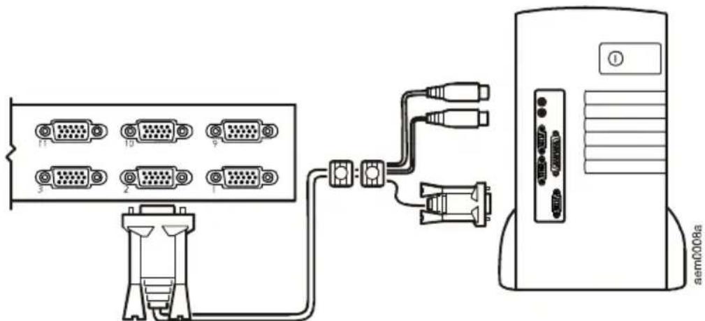
- Apply power to the system. See “How to Apply Power” on this page to complete the multi-switch installation.
How to Apply Power
To apply power for a multiple-switch system:
-
Plug in the power cable for the first KVM station. Wait for the Analog KVM Switch to discover and display its station ID on the Station ID LED. The station ID for the first station is 01.
-
Plug in the power cables for each Coaxial Analog KVM Switch on the system in order of second station, third station, and so on. In each case, wait for the station ID to be discovered and displayed on the current Coaxial Analog KVM Switch before plugging in the next one. The ID for the second station is 02, the ID for the third station is 03, etc.
-
After all the Coaxial Analog KVM Switches are running, apply power to the servers.
Turning off and restarting the Coaxial Analog KVM Switch
Always follow this procedure after removing power to the Coaxial Analog KVM Switch.
- Remove power from all connected servers.

Note: Unplug the power cord of any server with the Keyboard Power On function enabled; otherwise, the station continues to receive power from the servers.
-
Wait 10 seconds, and then plug in the Coaxial Analog KVM Switch.
-
Apply power to the servers only after the Coaxial Analog KVM Switch is running.
Operation—Coaxial Analog KVM Switch
Select ports using one of the following two methods: entering Hot Key combinations from the keyboard or using the On-Screen Display (OSD).
Hot Key mode
To activate or deactivate Hot Key mode, pressNUM LOCK and the hyphen (-) key at the same time.

Note: Release the hyphen (-) key within 1/2 second. Otherwise Hot Key activation stops and has no effect.
When Hot Key mode is active, the following changes occur:
- Caps Lock and Scroll Lock LEDs on the keyboard flash in succession. These stop flashing and revert to normal status after you exit Hot Key mode.
- The screen displays HotKey: and all subsequent keyed-in Hot Key information.
- Ordinary keyboard and mouse functions have no effect. You can input only Hot Key-compliant keystrokes and mouse clicks.
Press ESC to exit Hot Key mode.
See the User's Guide on the provided Coaxial Analog KVM Switch Utility CD for additional information about Hot Key functions.
Selecting the active port
Each server port is assigned a Port ID. Directly access any server connected to your Coaxial Analog KVM Switch System with a Hot Key combination that specifies the Station ID and the Port ID of the connected server's port.
To select the active port:
- Activate Hot Key mode by pressing NUM LOCK and the hyphen (-) key simultaneously.
- Enter the 2-digit station ID and 2-digit Port ID; do not separate these numbers with a space character.

Note: The Station ID and Port ID are displayed on the command line as you type each number. For example, enter 0305 to switch to Port 5 of the third Coaxial Analog KVM Switch in a multi-station chain. Use BACKSPACE to erase an incorrectly typed number.
- Press ENTER. The Coaxial Analog KVM Switch will focus on the designated server and exit Hot Key mode.
Hot Key summary table
The following table summarizes Hot Key operations on the Coaxial Analog KVM Switch:
See “Hot Key mode” on page 12 for instructions on activating Hot Key Mode.
| Hot Key Operation Description | |
| Station ID and Port ID numbers | Switch access to the server corresponding to the Port ID on the station corresponding to the Station ID. |
| T + number 1–255 | Sets the Auto Scan interval to a number of seconds from 1 to 255. |
| A Activates Auto Scan mode. | |
| P Pauses | Auto Scan. Press P or left-click the mouse.To resume Auto Scan, press any key or left-click the mouse. |
| ← | Activates Skip mode and skips from the current port to the preceding port. |
| → | Activates Skip mode and skips from the current port to the next port. |
| ↑ | Activates Skip mode and skips from the current port to the last port of the previous KVM station. |
| ↓ | Activates Skip mode and skips from the current port to the first port of the next KVM station. |
| B Toggles | the beeper on or off. |
| ESC Exits | Hot Key mode |
On Screen Display (OSD) operation
To activate the OSD main menu:
- Press the pre-assigned Hot Key, SCROLL LOCK, twice in rapid succession if you are already logged on.
Optionally, you can assign the CTRL key as the main menu Hot Key. See the User's Guide on the provided Coaxial Analog KVM Switch Utility CD for additional information.
-
When power is applied to the Coaxial Analog KVM Switch, the KVM Login screen appears. To access the OSD menus, do either of the following:
-
Enter a valid user name in the username field, pressTAB, enter a valid password in the password field, and press ENTER.
- For a first-time KVM OSD activation, or if the user name and password have not been set, leave the user name and password fields blank, and press ENTER.
The OSD main menu appears in Administrator mode (or User mode, if logged in as a user). Administrator mode provides access to both Administrator and User functions and lets you set up operations (including future password authorization).
OSD navigation
Use any of the following methods to navigate the OSD main menu screen:
- To hide the main menu and deactivate the OSD, pressESC, click the X at the upper-right hand corner of the screen, or right-click the mouse.
- To log off the OSD, press F8 or click F8 LOUT or the zZ button at the top of the screen, and answer Y to the prompt.
- To move up or down through the list, one line at a time, press the up or down arrow keys or click the up or down arrow symbols on the right scroll bar of the OSD.
- To move up or down through the list, one screen at a time, press the Page Up (PGUP) or Page Down (PGDN) key.
- To activate a port, double-click its name in the list, or highlight the name and press ENTER.
OSD functions
The OSD provides a series of function keys to configure and control various server operations. For example, you can switch to any port, scan selected ports, and limit the list of ports you want to view. You can also manage port names or make OSD setting adjustments.
To access any OSD function do one of the following:
- Press the desired function key on your keyboard.
- Click a function key menu option located at the top of the main menu screen.
For some functions, a submenu may appear.
Press ESC or click the X button in the upper right corner of the OSD to return to the preceding menu level.
See the User's Guide on the provided Coaxial Analog KVM Switch Utility CD for additional information on the OSD and its functions.
Specifications
Electrical
Power supply 100–240 V; 50 or 60 Hz
Connectors
| Console VGA | HDB-15F |
| Console K/M | 2-pin mini-DIN F (keyboard: purple; mouse: green) |
| CPU Ports | AP5202: (16) SPDB-15F; AP5201: (8) SPDB-15F |
| Serial connection | DB-25 F, 1 x DB-25 M |
| Remote access | RJ-45 |
| Firmware Upgrade | RJ-11 |
| Power | 3-pin AC power jack |
Emulation
| Keyboard | PS/2 |
| Mouse | PS/2 |
Scan interval User specified: 1 to 255 seconds
Power consumption DC 9 V, 8 W (max)
Physical
Switches
| NORMAL RECOVER(Firmware upgrade) | Slide switch |
| RESET | Semi-recessed push-button |
| LOCAL/REMOTE(remote access) | Locking push-button |
LEDs
| ON LINE | AP5202: 16 (Green); AP5201: 8 (Green) |
| SELECTED | AP5202: 16 (Orange); AP5201: 8 (Orange) |
| POWER | 1 (Blue) |
| STATION ID | Double 7 segment |
Video 1920 x 1440, DDC2B
Weight 7.90 lb (3.56 kg)
Dimensions (L x W x H) 17.00 x 8.25 x 1.75 in (431.8 x 209.6 x 44.45 mm)
Environmental
Temperature
| Operating | 0° to 50°C (32° to 122°F) |
| Storage | -20° to 60°C (-4° to 122°F) |
Humidity 0–95% RH
Product Description and Inventory
Overview
Use the Coaxial Analog KVM Console Extender to operate the Coaxial Analog KVM Switch from a remote console that is up to 500 ft (150 m) from the Switch.
Inventory
Quantity Item
| 1 Coaxial Analog KVM Console Extender(AP5203) |
| 1 Power adapter |
| 1 Warranty card |
Hardware requirements
Remote Console. To use the Coaxial Analog KVM Console Extender, you need the following equipment:
- VGA, SVGA, or Multisync monitor capable of the highest resolution that you plan to use on any server in the installation
- PS/2-style mouse
- PS/2-style keyboard

Note: If you plan to connect a DDC monitor to the local unit, the monitor that connects to the remote unit must be able to support the highest video resolution the DDC monitor can provide.
Cables. Use CAT-5e or CAT-6 UTP (Unshielded Twisted Pairs) cable (not included) to connect the Coaxial Analog KVM Console Extender to the Coaxial Analog KVM Switch. Cable of a lesser standard will cause the video signal to degrade. The CAT-5e or CAT-6 cable should be no longer than 500 ft (150 m).
Front view of Coaxial Analog KVM Console Extender
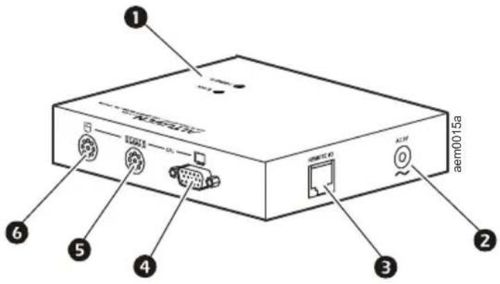
Item Description
| 1 | Port LEDs | Two LEDs (Power and Link) indicate operating status.A steady Power LED indicates the connection to the local unit is operating correctly.A blinking Power LED indicates that there is a problem with the connection to the local unit.When the Link LED is on, the remote console is active.When the Link LED is off, the local console is active or there is a problem with the connection to the local unit. |
| 2 | Power inlet AC power adapter cable inlet. | |
| 3 | Remote I/O port To use a remote console, plug a CAT-5e or CAT-6 cable into this port. | |
| 4 | Monitor port Connects to a VGA, SVGA, or Multisync monitor capable of the highest resolution that you plan to use on any server in the installation. | |
| 5 | Keyboard port Connects to a PS/2-style keyboard. | |
| 6 | Mouse port Connects to a PS/2-style mouse. | |
How to Install the Coaxial Analog KVM Console Extender
Pre-installation
Turn off power to all devices that you plan to connect. To prevent damage to your equipment because of static-electric discharge, ground all devices involved in the installation.

Warning: For safety and grounding instructions, consult your device manuals or contact the customer support department of the device manufacturer.
Installation
To install the Coaxial Analog KVM Console Extender:
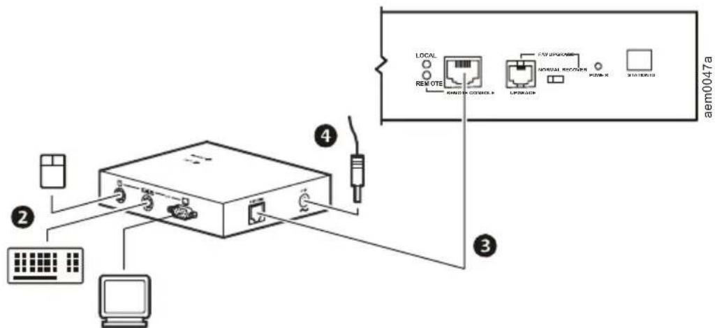
- Place the Coaxial Analog KVM Console Extender on a desk or flat surface within convenient reach of the keyboard, mouse, and monitor cables.
- Plug the keyboard, monitor, and mouse cables for the remote console devices into the appropriate ports of the Coaxial Analog KVM Console Extender (2).
- Plug either end of the CAT-5e or CAT-6 cable into the I/O port. Plug the other end into the Remote Console port of the Coaxial Analog KVM Switch③).
- Plug the power adapter (included) into an AC power source, then plug the power cable of the adapter into the Power Inlet of the Coaxial Analog KVM Console Extender (④).
-
Apply power to the Coaxial Analog KVM Switch by plugging the power cable into the port marked Power on the rear of the Coaxial Analog KVM Switch.
-
Apply power to the servers.
Operation—Coaxial Analog KVM Console Extender
The Coaxial Analog KVM Console Extender provides remote access to the Coaxial Analog KVM Switch. Control of the Coaxial Analog KVM Switch is shared serially; only one station can provide input at a time. The Local and Remote consoles can monitor output simultaneously, unless the Disable Remote option of the Coaxial Analog KVM Switch is activated.
The Local and Remote LEDs on the Coaxial Analog KVM Switch cycle back and forth alternatively when no activity is occurring on either console. When the user begins to type on the keyboard, or moves the mouse, the LED for that station will turn on to indicate which console (Local or Remote) has control. The other station will be locked out while the activity continues, although both consoles may continue to monitor the activity. When the user stops all activity for a period of approximately 5 seconds, the LEDs again begin to cycle and either station can take control.

Note: Two LEDs on the Coaxial Analog KVM Console Extender indicate operating status:
- When the Power LED is on and not blinking, the local connection is active.
- When the Link LED is on, the remote console is active.
See “Port LEDs” on page 18 for more information about the LEDs.
For security purposes, the remote console can be disabled. This prevents the remote console (the Coaxial Analog KVM Console Extender) from accessing the Coaxial Analog KVM Switch or any of the equipment attached to it. To disable the remote console, press the Disable Remote button on the Coaxial Analog KVM Switch. The Remote LED of the Coaxial Analog KVM Switch will turn off when remote access is disabled. To re-enable the remote console, press the Disable Remote button again; the Remote LED will begin to cycle on and off again, alternating with the Local LED, when remote access is enabled.

Note: The Remote console cannot disable the Local console, because only the local user has access to the Disable Remote button.
See “Operation—Coaxial Analog KVM Switch” on page 12 for information about accessing the ports of the Coaxial Analog KVM Switch.
Specifications
Electrical
| Connectors | |
| Console VGA | 1 x 15 pin HDB female |
| Console K/M | 1 x 6 pin mini-DIN female |
| KVM | RJ-45 |
| Power | External 9 V power supply |
| Power consumption AC 9 V 4.0 W (maximum) | |
Physical
| LEDs Power On (1)On Line (1) |
| Video resolution 1284 x 1024DDC; DDC2; DDC2B (local monitor only) |
| Housing Metal |
| Weight 0.44 lb (220 g) |
| Dimensions (L x W x H) 4.0 x 3.2 x 1.4 in (100 x 80 x 35 mm) |
APC Worldwide Customer Support
Customer support for this or any other APC product is available at no charge in any of the following ways:
- Visit the APC Web site to access documents in the APC Knowledge Base and to submit customer support requests.
- www.apc.com (Corporate Headquarters)
Connect to localized APC Web sites for specific countries, each of which provides customer support information.
- www.apc.com/support/
Global support searching APC Knowledge Base and using e-support.
- Contact an APC Customer Support center by telephone or e-mail.
- Regional centers
Direct InfraStruXure (1)(877)537-0607
Customer Support Line (toll free)
APC headquarters U.S., (1)(800)800-4272
Canada (toll free)
Latin America (1)(401)789-5735
(USA)
Europe, Middle East, (353)(91)702000
Africa (Ireland)
Western Europe (inc. +800 0272 0272
Scandinavia)
Japan (0) 36402-2001
Australia, New Zealand, (61) (2) 9955 9366
South Pacific area (Australia)
- Local, country-specific centers: go to www.apc.com/support/contact for contact information.
Contact the APC representative or other distributor from whom you purchased your APC product for information on how to obtain local customer support.
Entire contents copyright 2007 American Power Conversion Corporation. All rights reserved. Reproduction in whole or in part without permission is prohibited. APC, the APC logo, InfraStruXure, and NetShelter are trademarks of American Power Conversion Corporation. All other trademarks, product names, and corporate names are the property of their respective owners and are used for informational purposes only.
- Installation and Quick Start
- Coaxial Analog KVM Switch Coaxial Analog KVM Console Extender
- Coaxial Analog KVM Switch 1
- Product Description and Inventory....1
- How to Mount the Coaxial Analog KVM Switch....7
- How to Install a Single Coaxial Analog KVM Switch. 8
- How to Install Multiple Coaxial Analog KVM Switches ..... 9
- How to Apply Power....11
- Operation—Coaxial Analog KVM Switch ..... 12
- Specifications 16
- Coaxial Analog KVM Console Extender 17
- Product Description and Inventory....17
- How to Install the Coaxial Analog KVM Console Extender . . . 19
- Operation—Coaxial Analog KVM Console Extender ..... 20
- Specifications 21
- Product Description and Inventory
- Overview
- Inventory
- Hardware requirements
- Additional documentation
- Front panel of Coaxial Analog KVM Switch (AP5202 shown)
- Item Description
- Rear panel of Coaxial Analog KVM Switch (AP5202 shown)
- How to Mount the Coaxial Analog KVM Switch
- Mounting options
- How to Install a Single Coaxial Analog KVM Switch
- Pre-installation
- Single-station installation
- How to Install Multiple Coaxial Analog KVM Switches
- Serial connection
- How to Apply Power
- Turning off and restarting the Coaxial Analog KVM Switch
- Operation—Coaxial Analog KVM Switch
- Hot Key mode
- Selecting the active port
- Hot Key summary table
- On Screen Display (OSD) operation
- OSD navigation
- OSD functions
- Specifications
- Electrical
- Physical
- Environmental
- Front view of Coaxial Analog KVM Console Extender
- How to Install the Coaxial Analog KVM Console Extender
- Installation
- Operation—Coaxial Analog KVM Console Extender
- APC Worldwide Customer Support
Brand : APC
Model : AP5202
Category : Network switch