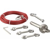
ZB0055 - Industrial accessory IFM - Free user manual and instructions
Find the device manual for free ZB0055 IFM in PDF.


| Product Type | Inductive Proximity Sensor |
| Brand | IFM |
| Model | ZB0055 |
| Dimensions (L x W x H) | 50 mm x 30 mm x 20 mm |
| Weight | 50 g |
| Power Supply | 24 V DC |
| Operating Temperature | -25°C to 70°C |
| Protection Rating | IP67 |
| Output Type | NPN or PNP (configurable) |
| Connection | M12 connector, 4-pin |
| Detection Range | 0-8 mm |
| Housing Material | Brass nickel-plated |
| Display | None |
| Functions | Non-contact metal detection, switching output |
| Maintenance | Clean housing with dry cloth; avoid solvents |
| Safety Instructions | Disconnect power before installation; observe ESD precautions |
| Spare Parts | Contact IFM for replacement connectors or mounting accessories |
| Certifications | CE, RoHS, cULus |
Frequently Asked Questions - ZB0055 IFM
User questions about ZB0055 IFM
0 question about this device. Answer the ones you know or ask your own.
Ask a new question about this device
Download the instructions for your Industrial accessory in PDF format for free! Find your manual ZB0055 - IFM and take your electronic device back in hand. On this page are published all the documents necessary for the use of your device. ZB0055 by IFM.
USER MANUAL ZB0055 IFM
Operating instructions Rope Tension Kit
UK
ZB0054 / ZB0055 ZB0056 / ZB0057 ZB0058 / ZB0059 ZB0060
1 Preliminary note
- An instruction is indicated by „▶“. Example: ▶ Mount the unit as shown.
• A reaction to the action is indicated by „>“.

Important note
Non-compliance can result in malfunction or interference.

Information
Supplementary note.
2 Safety instructions
- Please read the operating instructions prior to set-up of the device. Ensure that the product is suitable for your application without any restrictions.
- Improper or non-intended use may lead to malfunctions of the unit or to unwanted effects in your application.
• Installation, set-up, operation and maintenance of the unit must only be carried out by qualified personnel authorised by the machine operator.
3 Items supplied
| Description | Rope | Eyebolts | Tensioner | Allen Key |
| ZB0054 5m 3 1 1 | ||||
| ZB0055 10m 5 1 1 | ||||
| ZB0056 20m 9 1 1 | ||||
| ZB0057 50m 20 1 1 | ||||
| ZB0058 80m 30 2 1 | ||||
| ZB0059 100m 37 2 1 | ||||
| ZB0060 126m 45 2 1 |
4 Installation
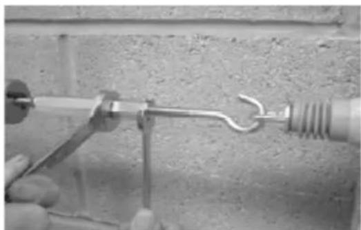
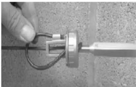
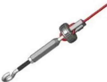
Installation of the rope and setting of the pull force are extremely simplified using the stainless steel rope tension kit. Just push the end of the rope through the holes on the rope tensioner and tighten with the Allen screw. Then set the correct pull force via the setting thread. Advantage: This setting is directly made on the safety rope e-stop switch so that the adjustment for the correct rope tension is directly indicated on the rope status display of the switch. Insert the free end of the rope into the intended clip.
▶
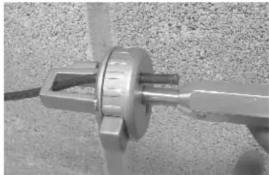
natural_image
Close-up of a metallic mechanical component with a central hub and mounting bracket, mounted on a textured surface (no visible text or symbols)1.

natural_image
Close-up of a hand holding a coiled cable or wire with a metallic connector (no visible text or symbols)2.
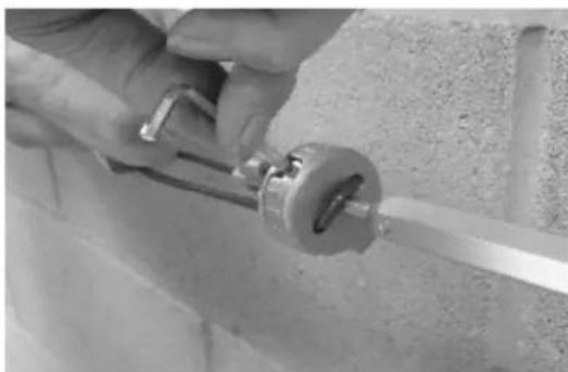
natural_image
Close-up of a hand using a tool to adjust or install a mechanical component (no visible text or symbols)3.
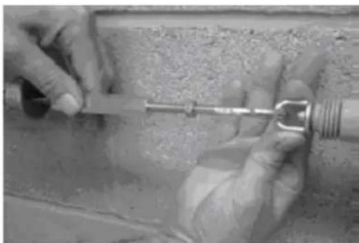
natural_image
Close-up of hands using a metal tool to apply material, no visible text or symbols4.
natural_image
Close-up of hands using a tool to connect two metallic components, one with a hook and the other with a coiled spring (no text or symbols visible)5.
natural_image
Close-up of a hand holding a metallic tool with wires, mounted on a textured surface (no visible text or symbols)6.

natural_image
Diagram of a yellow connector with a cable and terminal, showing internal components and wiring (no text or symbols)Tension the rope to mid position as indicated by the green arrows.
natural_image
3D rendering of a mechanical tool with a red wire and black handle (no text or symbols visible)Tensioner: tensile strength up to 1500N. Just mount and adjust the rope at the ends.
If the rope is shorter, it can also be fastened using a safety spring on one end. Pulleys may only be mounted so that the whole rope length is visible and accessible.
natural_image
Mechanical pulley or bracket component (no text or symbols visible)
natural_image
Pure mechanical spring bar with two circular end caps (no text or symbols)Safety spring
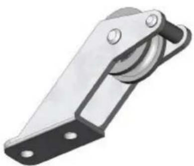
Stainless steel pulley for correctly reversing the direction of the rope. Suitable for inside and outside installation of the rope.

Eye bolts have to be installed between the switches across the whole length of the rope at a distance of min. 2.5m to max. 3m. The rope must be mounted at a distance of max. 500mm of the switch eye bolt or the tension spring (if it is used). It is important to note that the first 500mm cannot be used as part of the active protected area (E-stop triggering).

Installation of the components
5 Accessories
ZB0061: Safety spring, stainless steel, 220 mm
ZB0062: Pulley

Brand : IFM
Model : ZB0055
Category : Industrial accessory