
EC2110 - Dialogue and Process Module IFM - Free user manual and instructions
Find the device manual for free EC2110 IFM in PDF.


| Product Type | Mounting Frame for Panel Mounting |
| Compatible Devices | PDM360 NG (CR1080, CR1081, CR1082, CR1084, CR1085) |
| Material | Die-cast aluminum, powder coated (RAL 9005) |
| Mounting Orientation | Horizontal, vertical, or upside-down |
| Panel Thickness | 1 to 10 mm |
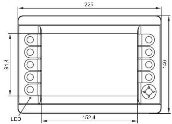
| Cutout Dimensions (W x H) | 183 ±0.5 mm x 136 ±0.5 mm |
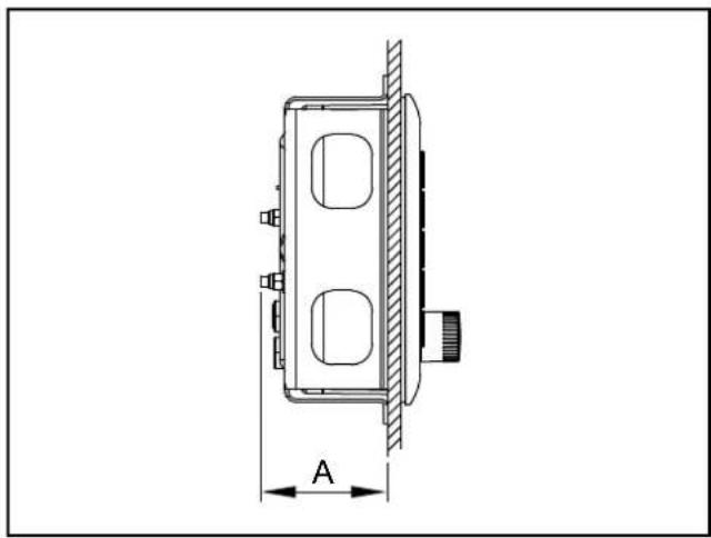
| Installation Depth | Approx. 60 to 65 mm (depending on panel thickness and set screws) |
| Tightening Torque | 5 ±0.5 Nm for M5 hexagon nuts |
| Included Accessories | M5 hexagon nuts, washers, M5 set screws, seal |
| Protection Rating (with module) | IP65 or IP67 depending on module variant |
| Operating Temperature | -30 to 65 °C |
| Storage Temperature | -30 to 80 °C |
| Weight (approximate) | 0.5 kg |
| Maintenance | Clean with a soft, dry cloth; avoid aggressive chemicals |
| Safety | Use only approved accessories; observe EMC directives |
Frequently Asked Questions - EC2110 IFM
User questions about EC2110 IFM
0 question about this device. Answer the ones you know or ask your own.
Ask a new question about this device
Download the instructions for your Dialogue and Process Module in PDF format for free! Find your manual EC2110 - IFM and take your electronic device back in hand. On this page are published all the documents necessary for the use of your device. EC2110 by IFM.
USER MANUAL EC2110 IFM
Installation instructions
Process and dialogue module
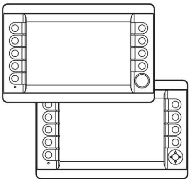
PDM360 NG
UK
CR1080 CR9223
CR1081 CR9224
CR1082 --
CR1084 CR9226
CR1085 CR9227
natural_image
Technical line drawing of a mechanical assembly with two views (top and side), no text or symbols present.Contents
1 Preliminary note 4
1.1 Symbols used.... 4
1.2 Warning signs used 4
2 Safety instructions 5
2.1 General....5
2.2 Target group 5
2.3 Electrical connection 5
2.4 Tampering with the device 5
2.5 Electromagnetic compatibility.... 5
3 Functions and features 6
3.1 Application example 6
3.2 Overview of the common characteristics 7
3.3 Distinctive features 7
4 Installation....8
4.1 Mounting accessory 8
4.2 General installation instructions 8
4.2.1 Locator for mounting accessories 8
4.2.2 Orientation of the device with panel and surface mounting ..... 9
4.2.3 Light sensor 9
4.2.4 Protective film for the touch screen (CR1082) 9
4.3 Panel mounting using the mounting frame.... 10
4.3.1 Mounting steps....11
4.4 Surface mounting with RAM® mount system 13
4.4.1 Mounting steps.... 13
5 Electrical connection.... 14
5.1 Connection accessories 14
5.2 General electrical connection 14
5.2.1 Cover all unused connectors 14
5.3 Operating voltage and fuses 15
5.3.1 Voltage supply of the switching output via clamp 30 15
5.4 Ground connection 15
5.5 Ethernet interface 17
5.5.1 Ethernet cameras.... 17
5.6 Analogue video inputs (only CR1082/84/85) 17
5.7 USB interfaces 18
5.7.1 USB connection via M12 connector.... 18
5.7.2 Short-circuit protection 19
5.7.3 USB connection behind the service cover 19
6 Set-up....20
6.1 General....20
6.2 First steps.... 20
6.3 Set-up....20
6.4 Required documentation 21
7 Technical data.... 22
7.1 CR1080 22
7.2 CR1081 26
7.3 CR1082 30
7.4 CR1084 35
7.5 CR1085 40
8 Maintenance, repair and disposal. 45
8.1 Battery change 45
8.2 Cleaning the display surface 45
8.3 Cleaning the housing surface.... 46
8.4 Repair.... 46
8.5 Disposal 46
9 Approvals / standards 46
This document is the original instructions.
Licences and trademarks
All trademarks and company names are subject to the copyright of the respective companies.
Validity of these instructions
These installation instructions are valid from the following device status:
CR1080AG, CR1081AF, CR1082AD, CR1084AE, CR1085AE, CR922xAA
1 Preliminary note
This document applies to devices of the type "PDM360 NG". These instructions are part of the device.
This document is intended for specialists. These specialists are people who are qualified by their appropriate training and their experience to see risks and to avoid possible hazards that may be caused during operation or maintenance of the device. The document contains information about the correct handling of the device.
Read this document before use to familiarise yourself with operating conditions, installation and operation. Keep this document during the entire duration of use of the device.
Adhere to the safety instructions.
1.1 Symbols used
▶ Instructions
Reaction, result
[...] Designation of pushbuttons, buttons or indications
→ Cross-reference

Important note
Non-compliance can result in malfunction or interference.

Information
Supplementary note
1.2 Warning signs used
WARNING
Warning of serious personal injury.
Death or serious irreversible injuries may result.
CAUTION
Warning of personal injury.
Slight reversible injuries may result.
NOTE
Warning of damage to property.
2 Safety instructions
2.1 General
These instructions contain texts and figures concerning the correct handling of the device and must be read before installation or use.
Observe the operating instructions. Non-observance of the instructions, operation which is not in accordance with use as prescribed below, wrong installation or incorrect handling can seriously affect the safety of operators and machinery.
2.2 Target group
These instructions are intended for authorised persons according to the EMC and low-voltage directives. The device must only be installed, connected and put into operation by a qualified electrician.
2.3 Electrical connection
Disconnect the unit externally before handling it. If necessary, also disconnect any independently supplied output load circuits.
If the device is not supplied by the mobile on-board system (12/24 V battery operation), it must be ensured that the external voltage is generated and supplied according to the criteria for safety extra-low voltage (SELV) as this voltage is supplied without further measures to the connected controller, the sensors and the actuators.
The wiring of all signals in connection with the SELV circuit of the device must also comply with the SELV criteria (safety extra-low voltage, safe electrical isolation from other electric circuits).
If the supplied SELV voltage is externally grounded (SELV becomes PELV), the responsibility lies with the user and the respective national installation regulations must be complied with. All statements in this document refer to the device the SELV voltage of which is not grounded.
The connections may only be supplied with the signals indicated in the technical data and/or on the device label and only the approved accessories of ifm electronic gmbh may be connected.
2.4 Tampering with the device
In case of malfunctions or uncertainties please contact the manufacturer. Tampering with the device can seriously affect the safety of operators and machinery. It is not permitted and leads to the exclusion of any liability and warranty claims.
2.5 Electromagnetic compatibility
This is a class A product. It can cause radio interference in domestic areas. In this case the operator may be requested to take appropriate measures.
3 Functions and features
The PDM360 NG process and dialogue module is a programmable graphic display for controlling, parameter-setting and operation of mobile machines and plants.
Communication with other system components, e.g. decentralised I/O modules, is handled via a CAN interface using the CANopen protocol.
For service purposes, additional interfaces such as Ethernet, USB or 3 further CAN interfaces are available. Together with the Linux operating system they form a universal platform for networking and communication with other CAN devices, networks or PCs.
WARNING
The PDM360 NG process and dialogue module is not approved for safety-related tasks in the sense of the safety of persons.
3.1 Application example
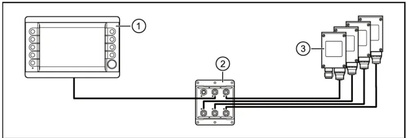
Networking of 4 Ethernet cameras with a PDM360 NG
- PDM360 NG (e.g. CR1080)
- Ethernet switch (e.g. EC2095)
- Ethernet cameras (e.g. 4 x O2M11x)
3.2 Overview of the common characteristics
- 7" Colour display
- Programmable backlit function keys
- Closed metal housing suitable for panel mounting and surface mounting outside or in the cabin
- Freely programmable to IEC 61131-3 with target visualisation
- 32-bit controller and Embedded Linux operating system
- CAN interfaces with CANopen and SAE J 1939 protocol.
- Ethernet and USB interfaces
- Multi-function input (digital/analogue)
- Switching output (digital)
3.3 Distinctive features
natural_image
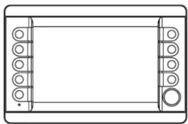
Top-down schematic of a rectangular device with internal components and mounting holes (no text or symbols)CR1080/84
9 function keys
1 encoder
natural_image
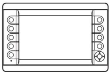
Pure technical line drawing of a rectangular frame with rounded corners and circular cutouts, no text or symbols present.CR1081/82/85
9 function keys
1 rocker switch
| CR1080CR9223* | CR1081CR9224* | CR1082-- | CR1084CR9226* | CR1085CR9227* | |
| Function keys 9 9 9 9 9 | |||||
| Encoder ● -- ● - | |||||
| Rocker switch - ● ● - ● | |||||
| Analogue video input -- ● ● ● | |||||
| Touch screen -- ●** -- |
- = available *) Version with optical bonding
**) Protective film for the touch screen supplied with the unit
4 Installation
4.1 Mounting accessory
The unit is supplied without mounting accessories.
Depending on the intended location and type of mounting the following mounting accessories are available:
- EC2110, mounting frame for panel mounting incl. mounting material and seal
- EC1410..EC1414, RAM® mount system for surface mounting
You can find more information about the available accessories at: www.ifm.com → data sheet search → e.g. CR1080 → Accessories
4.2 General installation instructions
4.2.1 Locator for mounting accessories
The back of the unit has been prepared for fixing the mounting accessories.
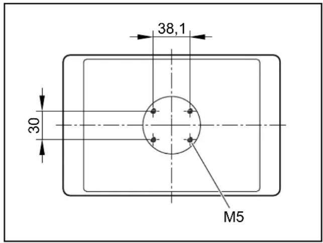
Locator for mounting accessories (back of the unit)
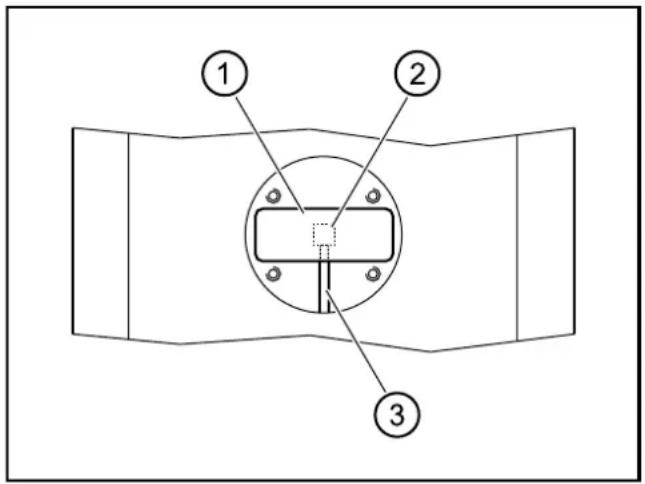
1: type label
2: pressure compensation element
3: ventilation duct
Usable M5 thread depth: ≤ 8 mm
The hole dimensions correspond to the RAM ^® mount mounting plate ( 4.4).
ATTENTION
A pressure compensation element is located under the type label. Use of elastic materials to seal or close the associated ventilation duct may cause damage to the device.
▶ Do not use sealing materials in the ventilation duct area.
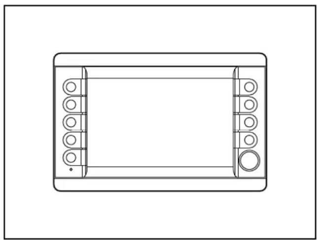
4.2.2 Orientation of the device with panel and surface mounting
natural_image
Top-down line drawing of a rectangular device with internal compartments and circular elements (no text or symbols)Horizontal orientation for panel and surface mounting
UK
4.2.3 Light sensor
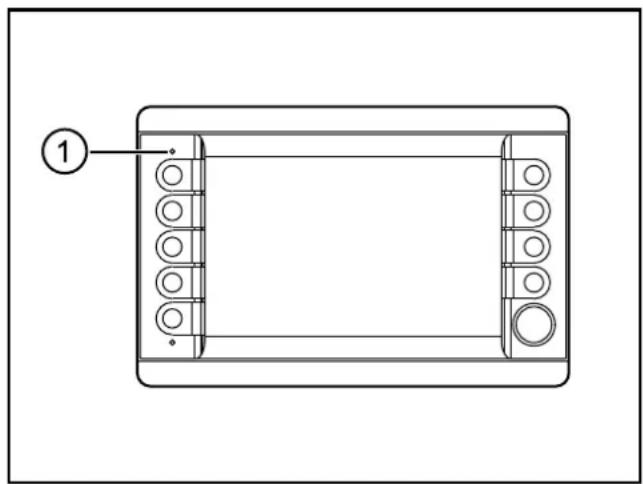
The device is equipped with a light sensor. It is used for automatic brightness adaptation of the display and the operating elements to the ambient brightness.
natural_image
Technical line drawing of a rectangular device with internal components and a numbered label (1), no readable text or symbols present.1: Light sensor
▶ Do not cover up the light sensor by construction measures.
4.2.4 Protective film for the touch screen (CR1082)
The unit is designed for use in harsh conditions in mobile machines. Nevertheless, the integrated glass touch screen cannot be used under all operating conditions.
Therefore, a protective film (type CR108x) is supplied that can be applied to the front glass before the unit is put into operation. It supplies additional protection for the touch screen in case of increased strain of the surface.
We recommend a timely replacement of the protective film in cases of damage or heavy wear. Further protective films can be purchased at
www.Schutzfolien24.com by indicating the type of unit CR108x.
4.3 Panel mounting using the mounting frame
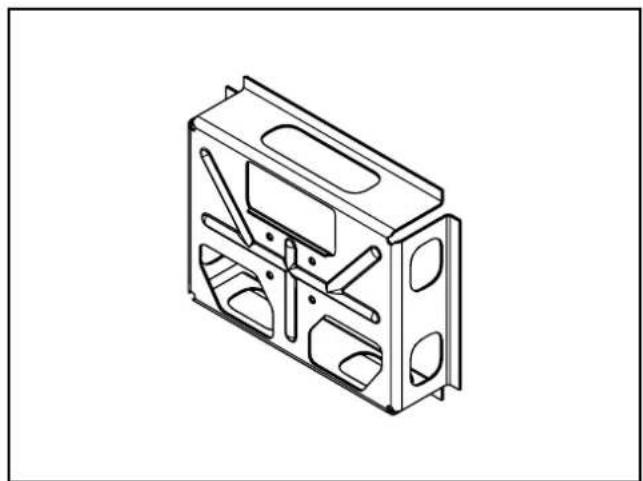
The mounting frame ensures horizontal, vertical or up-side down mounting of the device in a panel cutout.
This type of mounting is suited for materials with a thickness from 1 to 10 mm.
The M5 hexagon nuts, washers, M5 set screws and a seal are supplied with the device.
natural_image
Technical line drawing of a mechanical housing or enclosure with cutouts and internal components (no text or symbols)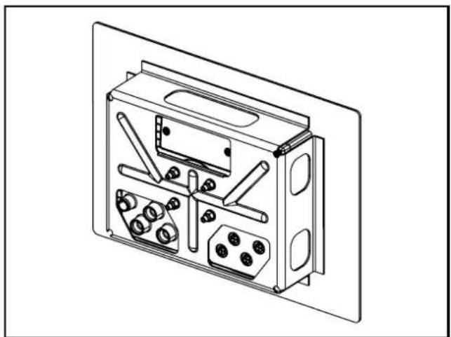
natural_image
Technical line drawing of an electronic device casing with internal components (no text or symbols)Mounting frame Dialogue module with mounted mounting frame

Only insert the mounting frame together with the seal.
4.3.1 Mounting steps
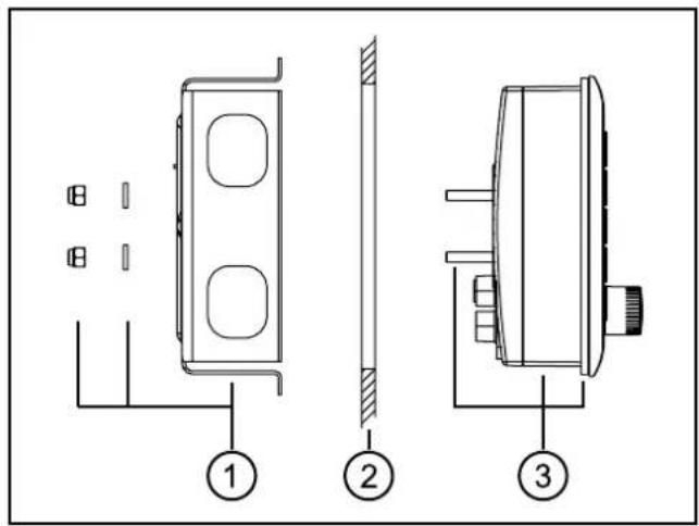
Mounting principle
1: mounting frame with M5 hexagon nuts (self-locking) and washers
2: panel cutout
3: dialogue module with attached seal and screwed set screws
▶ Make a cut-out.
Cutout for panel mounting ( 7 Technical data)
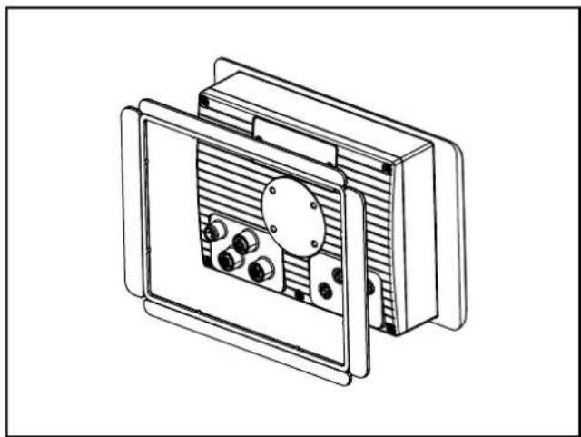
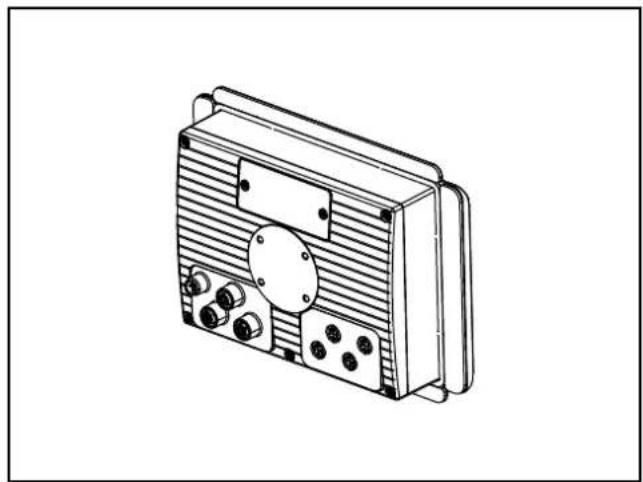
▶ Attaching the seal to the unit.
Procedure:
- Remove 3 protective films from the seal (2 short sides and 1 continuous, narrow strip).
The protective films on the two long sides remain on the seal.
- Place the seal onto the device from the back and attach it.
- Remove protruding long sides of the seal.
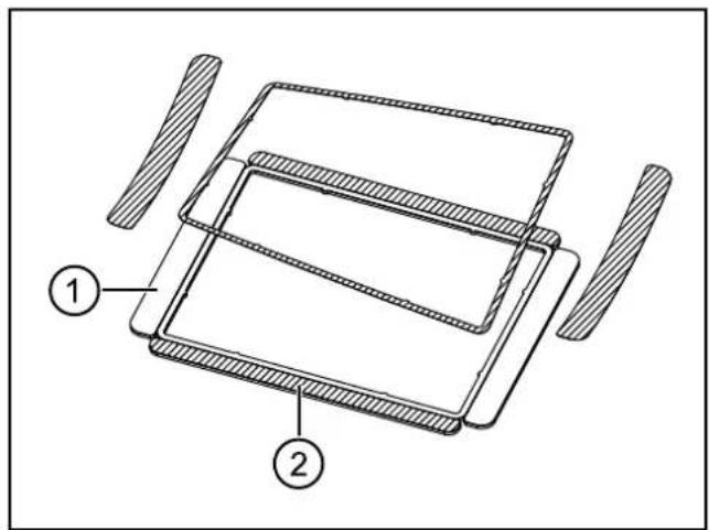
- adhesive area
- protective films remaining on the seal
natural_image
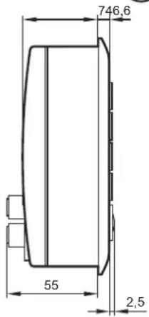
Technical line drawing of a mechanical component with dimension label A (no text or symbols present)Installation depth A: approx. 60...65 mm (depending on the panel thickness and the length of the set screws, without connector)
natural_image
Technical line drawing of a mechanical device with internal components and mounting brackets (no text or symbols)
natural_image
Technical line drawing of a mechanical device with internal components and mounting brackets (no text or symbols)Place the seal onto the device
natural_image
Technical line drawing of a rectangular electronic device with internal components and mounting holes (no text or symbols)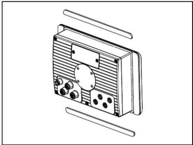
natural_image
Line drawing of a portable electronic device with ventilation slots and buttons (no text or symbols)Attached seal Removed long sides
▶ Screw the set screws into the M5 thread on the back of the device. (→ 4.2.1 Locator for mounting accessories)
Select the set screws in accordance with the panel thickness.
| Panel thickness Set screws | |
| 1... 5 mm M5 x 25 | |
| > 5...10 mm M5 x 30 |
▶ Insert the device into the cutout.
▶ Screw the mounting frame to the back of the device.
Tightening torque of the M5 hexagon nuts: 5 ±0.5 Nm
4.4 Surface mounting with RAM ^® mount system
Using the RAM ^® mount components, available as accessories, the dialogue unit can be used as a firmly mounted desktop unit. Two balls allow a variable orientation of the unit.
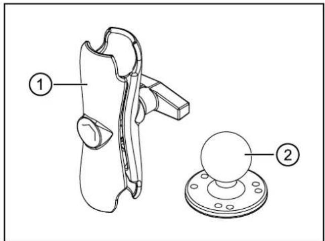
RAM ^® mount components
1: mounting arm with fastening screw
2: mounting plate with ball
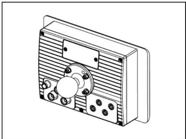
natural_image
Technical line drawing of a mechanical device with no visible text or symbolsDialogue module with mounted RAM ^® mount system
UK
4.4.1 Mounting steps
▶ Screw the mounting plate onto an even surface.
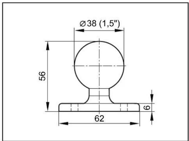
Mounting plate with ball Hole dimensions
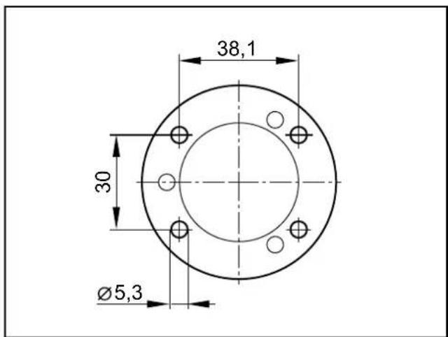
Tightening torque: 5^±0.5 (Nm
▶ Screw the second mounting plate to the back of the device.
▶ Slightly loosen the fastening screw of the mounting arm.
▶ Place the mounting arm onto the balls and tighten the fastening screw.
You can find more information about the available RAM® mount components at: www.ifm.com → data sheet search → CR1080 → Accessories
5 Electrical connection
5.1 Connection accessories
You can find more information about the available accessories at: www.ifm.com → data sheet search → CR1080 → Accessories or www.ifm.com → Products → Accessories → Connection technology
5.2 General electrical connection
Wiring of the M12 connectors ( 7 Technical data)
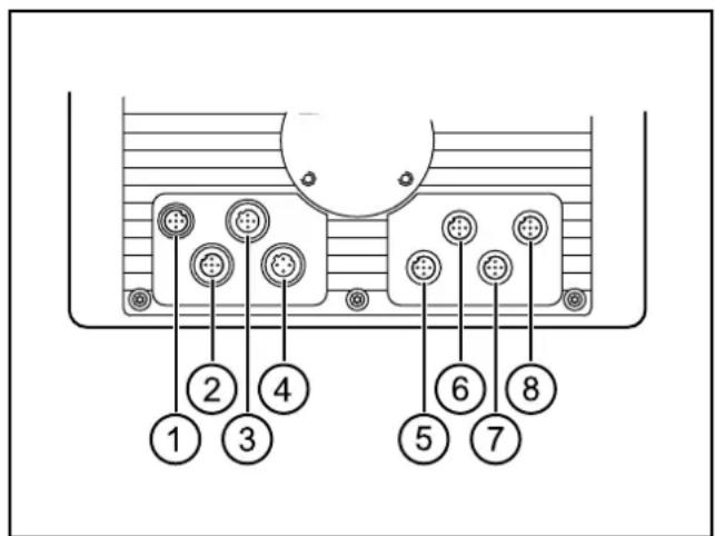
M12 connector (back of the unit)
1: Supply, input/output
2: CAN1
3: USB
4: Ethernet
5: CAN2
6: CAN3/4
7: Analogue video input (CR1082/84/85 only)
8: N/A
NOTE
Wrong connection may cause damage to the device.
▶ Observe the safety instructions.
NOTE
The short-circuit / reverse polarity protection of the device applies to the operating voltage connections. A short circuit between operating voltage (+24 V DC) and CAN_GND damage the device.
▶ Basically all supply and signal cables must be laid separately.
▶ Lay supply and signal cables away from the device using the shortest possible route.
▶ All connected cables must be provided with a strain relief.
5.2.1 Cover all unused connectors
NOTE
Moisture penetrating through unused or unprotected connectors may destroy the device.
▶ Cover unused connectors with protective caps.
5.3 Operating voltage and fuses
▶ To protect the device use fuses for the operating voltages.
| Description Potential Connector 1 Fuse | |||
| Operating voltage clamp 30 | 10...32 V DCpositive directly from the battery | pin 1 max. 5 A | |
| Operating voltage clamp 15 | 10...32 V DCCONNECTed positive from the ignition-starter switch | pin 5 max. 5 A | |
Terminal designation to DIN 72552
5.3.1 Voltage supply of the switching output via clamp 30
As from the following device statuses the switching output is supplied via clamp 30. The output can still switch even if the ignition voltage is switched off and the latching function is activated.
| Article no. Valid as from | device status Introduction | |
| CR1080 AE 01.05.2014 | ||
| CR1081 AD | 01.05.2014 | |
| CR1082 AB 27.04.2013 | ||
| CR1084 AB 28.02.2014 | ||
| CR1085 AB 28.02.2014 |
The device status is noted on the type label

For older device statuses the switching output was supplied via clamp 15. If the ignition voltage is switched off (by turning the ignition key to OFF) the output is switched off at the same time.
5.4 Ground connection

To ensure the protection of the device against electrical interference and to ensure the safe function of the device, the housing has to be connected to the body / GND of the supply using the shortest possible route.
▶ Establish the connection between the device and the ground of the vehicle using the intended screw for RAM ^® Mount installation.
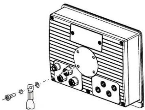
natural_image
Technical line drawing of a device rear panel with connectors and a bulb, showing no text or symbolsGND connection

To avoid contact corrosion on the shield connection of the device, do not use any copper or nickel-plated materials for the bolting elements!
In very corrosive environments such as extremely salty air, use screws with surface finishing on a zinc/nickel basis with thick-film passivation and sealing.
5.5 Ethernet interface
▶ Use a shielded CAT5 cable.
STP, Shielded Twisted Pair, according to EIA/TIA-568.
Max. length 25 m

The max. cable length depends for example on the bus topology, the selected operating mode (10/100 Mbits/s) or the quality of the connectors.
▶ Use screened connector housings and connect the screen of the Ethernet cable to the connector housing.
▶ Do not lay the Ethernet cable in parallel to live cables.

Interference due to external influences
Faulty or insufficient radio interference suppressors in other electrical equipment, such as inverters or generators, as well as voltage fluctuations when switching on/off electric loads may lead to problems with the data transmission.
5.5.1 Ethernet cameras
The device supports ifm Ethernet cameras (e.g. O2M110) firmware 5.1001 or higher.
Networking example ( 3.1 Application example)
5.6 Analogue video inputs (only CR1082/84/85)
▶ When using the analogue video inputs, please provide all connection cables with ferrite sleeves.
Recommendation: impedance 321 Ω (100 MHz)

The ferrite sleeves ensure CE/E1 conformity and suppress conducted interference.
5.7 USB interfaces

The USB interfaces are used for the temporary connection of an external keyboard, a mouse or a USB memory stick.
They are not intended for actual operation.
▶ Remove the USB devices after their use.
5.7.1 USB connection via M12 connector
Wiring ( 7 Technical data)
This USB interface is connected to a USB connector in the control panel or in the dashboard.
It is used for the temporary connection of operating devices (USB mouse / keyboard) and storage media (e.g. USB memory stick).
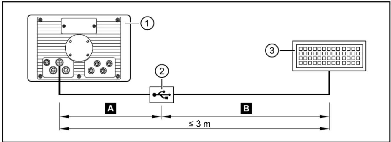
USB connection via M12 connector
1: Dialogue module
2: USB connector, for example in the control panel or in the dashboard
3: USB keyboard, mouse or memory stick
A Permanent connection: Dialogue module – USB connector
▶ Use prewired cable.
(e.g. art. no. EC2099, M12 connector, B-coded on USB socket, type A, watertight, cable length 1.5 m, wires twisted and screened)
▶ Use only cables with twisted and screened wires for individual wiring. Keep length "A" as short as possible and position the USB connector in immediate vicinity to the dialogue module. The length "A" considerably influences the quality of the USB data transmission.
B Temporary connection: USB connector – USB device
▶ Use a connection cable with the designation "Full Speed/High Speed" (= USB connection cable with twisted and screened cores).
▶ Do not make a connection using several USB connection cables.
▶ Remove connection cable after the programming or service works.
5.7.2 Short-circuit protection
NOTE
The USB interface (M12 connector) is not protected against short circuits with a live wire outside the following voltage ranges:
-data 0.3...3.6 V DC (3: pin 2)
+data 0.3...3.6 V DC (3: pin 3)
ID 0.3...3.6 V DC (3: pin 4)
A short circuit will destruct the USB interface.
5.7.3 USB connection behind the service cover
▶ Remove the service cover on the back of the unit.
(2 M3 socket head screws)
▶ Connect the USB keyboard, mouse or memory stick with the USB interface.
▶ Remove the USB devices after their use and close the service cover again.
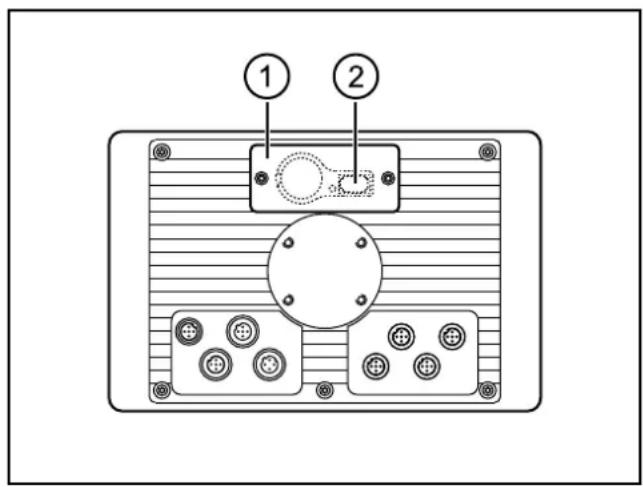
1: service cover
2: USB socket, type A
6 Set-up
6.1 General
As delivered the device is prepared for programming with CODESYS version 2.3 or higher.
Factory setting:
IP address: 192.168.82.247
Subnet mask: 255.255.255.0

The user is responsible for the safe function of the application programs which he created himself. If necessary, he must additionally have an approval test carry out by corresponding supervisory and test organisations according to the national regulations.
6.2 First steps
▶ Connect the device to the notebook/PC via the Ethernet interface.
▶ Switch on the notebook/PC; check the IP settings of the notebook/PC and change them if necessary.
Internet protocol: TCP/IP:
IP address: 192.168.82.xxx (except for .247, s.a.)
Subnet mask: 255.255.255.0
Gateway IP address: 192.168.100.1
▶ Switch on the operating voltage of the dialogue module.
Shortly after switch-on of the unit the start image is shown for approx. 10 to 15 seconds.
During this time booting is running in the background.
After booting the set-up program opens automatically.
6.3 Set-up
The set-up allows the setting of the device parameters.
The menu items are selected using the function keys or via a connected USB keyboard.
| Function keys USB keyboard Description | |||
| Left SELECT | TAB select menu item | ||
| SAVE | F3 | save entries | |
| Right | UP | arrow up | increase value or variable |
| DOWN | arrow down | decrease value or variable | |
| ENTER | ENTER | open selected menu item | |
| EXIT | ESC | leave set-upleave menu itementries will not be saved | |
After leaving the set-up a project can be loaded.
Libraries (.lib) are available for the use of the operating elements, interfaces and other internal functions of the device. They have to be integrated into the application program.
6.4 Required documentation
In addition to the CODESYS programming system, the following documents are required for programming and set-up of the device:
- Programming manual CODESYS V2.3
(alternatively as online help)
- PDM360 NG system manual
(alternatively as online help)
The manuals can be downloaded from the internet:
www.ifm.com → data sheet search → CR1080 → Additional data
CODESYS and PDM360 NG online help:
www.ifm.com → Service → Download → Control systems*
*) Download area with registration
7 Technical data
7.1 CR1080
CR1080
Process and dialogue module PDM360 NG
7" colour display
9 freely programmable backlit
function keys
encoder
with pushbutton
1 input / 1 output
10...32 V DC
CE
E1
Technical data Programmable graphic
Display
| Display TFT LCD colour display |
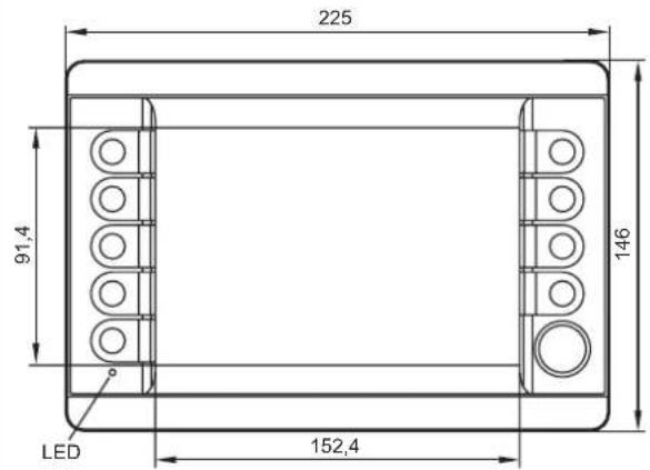
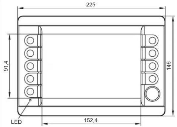
| Format 15:9 (wide VGA), 152.4 x 91.4 mm, 7" diagonal |
| Resolution 800 x 480 pixels |
| Alignment horizontal |
| Surface glass with anti-glare coating |
| Colours 262.144 (18 bits) |
| Background illumination LED (lifetime ≥ 50,000 h) |
| Brightness ≥ 400 cd/m2, typically 500 cd/m2 |
| Contrast ratio |
| Character sets |
Mechanical data
| Mounting variants |
| Dimensions (W x H x D) |
| Cutout for panel mounting (W x H) |
| Housing material |
| Pushbuttons |
| Encoder |
| Background illumination operating elements |
| Protection rating |
| Operating temperature |
| Storage temperature |
| Weight |
display for controlling, parameter-setting and operation of mobile machines and plants
| m, 7" diagonal |
| (adjustable 0...100%, increments 1%) |
| ≥ 500:1, typically 600:1 |
| can be uploaded individually and is freely scalable |
| preinstalled: ifm ISO fonts with vehicle-specific symbols, Arial, Courier |
panel mounting with mounting frame surface mounting with RAM ^® mount system (mounting accessories not included)
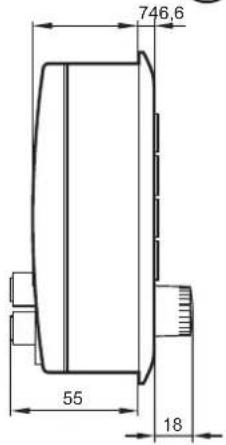
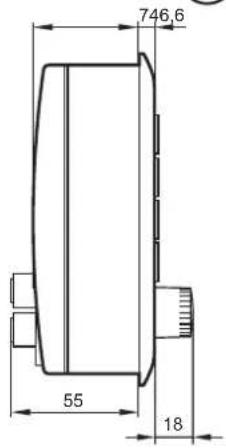
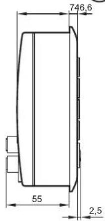
| 225 x 146 x 80 mm |
| 183 ± 0.5 x 136 ± 0.5 mm |
| die-cast aluminium housing, powder coating (RAL 9005) |
| 9 function keys (silicone keyboard) with tactile feedback freely programmable (softkey function) |
| lifetime ≥ 1,000,000 activations |
| with photoelectric rotation detection,latching and central mechanical pushbuttonlifetime ≥ 1,000,000 cycles |
| LED (brightness adjustable) |
| IP 65 (with mounted connectors and/or protective caps) |
| -30...65°C |
| -30...80°C |
| approx. 1.5 kg |
| CR1080 Technical data | |
| Electrical data | |
| Operating voltage 10...32 V DC | |
| Overvoltage detection | at U_B > 32 V |
| Overvoltage shutdown | at U_B > 34 V (hysteresis 1 V, i.e. switching on again at U_B < 33 V) |
| Undervoltage detection | at U_B < 10 V |
| Undervoltage shutdown | at U_B < 8 V (hysteresis 1 V, i.e. switching on again at U_B > 9 V) |
| Accuracy | 3 % FS |
| Current consumption 300 mA (without external load at 24 V DC) | |
| Short-circuit / reverse polarity protection electronic | |
| Processor MPC5121, 32 bits, 400 MHz | |
| Total memory 256-Mbyte RAM / 128-Mbyte flash / 1-Gbyte internal mass storage | |
| Memory allocation see system manual PDM360 NGwww.ifm.com → Data sheet direct: → CR1080 → Additional data | |
| Interfaces | |
| CAN 1...4 CAN interface 2.0 A/B, ISO 11898 | 50 Kbits/s...1 Mbit/s (default 125 Kbits/s)CANopen, CiA DS 301 version 4, CiA DS 401 version 1.4or SAE J 1939 or free protocol (Raw CAN)max. current load VBB_c ≤ 400 mA (protected by multi fuse) |
| Ethernet transmission rate 10/100 Mbits/s | |
| USB 2 x USB 2.0 full speed, transmission rate up to 12 Mbit/sUSB master operation (service and maintenance connection for keyboard, mouse etc.)output current per interface ≤ 500 mA | |
| Analogue video input - | |
| Input | confi gurabledigital for positive / negative sensor signalsanalogue 0...10, 0...32 V, 0...20 mA, ratiometric |
| Output | digital, positive switching (high side)supply via terminal 30 |
| Characteristics of the input | Resolution 8 bits |
| Accuracy ± 3 % FS | |
| Current input 0...20 mA | Input resistance 390 Ω |
| Input frequency 10 Hz | |
| Voltage input 0...10 V | Input resistance 65.6 kΩ |
| Input frequency 10 Hz | |
| Voltage input 0...32 V | Input resistance 50.7 kΩ |
| Input frequency 10 Hz | |
| Voltage input ratiometric | Input resistance 50.7 kΩ |
| Input frequency 10 Hz | |
| Digital input | Input resistance 3.2 kΩ |
| Input frequency 10 Hz | |
| Switch-on level > 0.7 U_s | |
| Switch-off level < 0.3 U_s | |
| Characteristics of the output | Switching voltage 10...32 V DC |
| Switching current ≤ 1 A | |
| Free-wheeling diodes integrated | |
| Software/programming | |
| Operating system | Embedded Linux 2.6 |
| Programming system | CODESYS version 2.3 or CODESYS from version 3.5 SP8 (IEC 61131-3) |
| Graphic functions | via integrated target visualisation |
ifm electronic gmbh • Friedrichstraße 1 • 45128 Essen
We reserve the right to make technical alterations without prior notice! 12.01.2018CR1080 / page 2
| CR1080 Technical data | |||
| Other features | |||
| Acoustic signal output integrated buzzer, tone duration and pitch programmable | |||
| Temperature monitoring 2 integrated sensors for measuring the temperature inside the housing | |||
| Brightness adaptation light sensor in the front of the device to adapt the brightness of the display and the operating elements | |||
| Clock / Battery real-time clock (RTC), battery buff ered / CR2032 (3 V, 230 mAh) | |||
| Status LED RGB LED, colours and states programmable by means of the application software | |||
| Operating states (preset) | Colour Status Description | ||
| - permanently off no operating voltage | |||
| green 5 Hz boot process application | |||
| 2 Hz application running (RUN) or set-up running | |||
| permanently on | application has stopped (STOP) or no project available | ||
| red | 2 Hz application is running with an error (RUN with error) | ||
| permanently on | system error (fatal error), device is in reset (e.g. internal voltage error) | ||
| red/orange | 2 Hz colour change | overtemperature/undertemperature, device is in reset until temperature in normal range | |
| orange | 5 Hz boot process system recovery/update | ||
| 2 Hz system recovery/update running | |||
| briefly on | System reset | ||
| Test standards and regulations | |||
| CE marking | EN 61000-6-2 Electromagnetic compatibility (EMC) Immunity | ||
| EN 61000-6-4 Electromagnetic compatibility (EMC) Emission standard | |||
| E1 marking | UN/ECE-R10 Emissions Immunity with 100 V/m | ||
| Electrical tests | ISO 7637-2 Pulse 1, severity level: IV; function state C Pulse 2a, severity level: IV; function state A Pulse 2b, severity level: IV; function state C Pulse 3a, severity level: IV; function state A Pulse 3b, severity level: IV; function state A Pulse 4, severity level: IV; function state A Pulse 5, severity level: III; function state C data valid for the 24V system | ||
| Climatic tests | EN 60068-2-30 Damp heat, cyclic upper temperature 55°C, number of cycles: 6 | ||
| EN 60068-2-78 Damp heat, steady state test temperature 40°C / 93% RH, test duration: 21 days | |||
| EN 60068-2-52 Salt spray test severity level 3 (vehicle) | |||
| Mechanical tests ISO 16750-3 | Test VII; Vibration, random mounting location: vehicle body | ||
| EN 60068-2-6 Vibration, sinusoidal 10...500 Hz; 0.72 mm/10 g; 10 cycles/axis | |||
| ISO 16750-3 Bumps 30 g / 6 ms; 24,000 shocks | |||
| Tests for railway applications | EN 50155 clause 12.2 mechanical/climatic tests | ||
| EN 50121-3-2 EMC noise emission and noise immunity additional information on request | |||
ifm electronic gmbh • Friedrichstraße 1 • 45128 Essen
We reserve the right to make technical alterations without prior notice! 12.01.2018CR1080 / page 3
CR1080 Technical data
Back of the unit
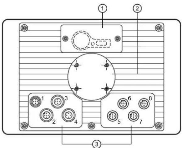
1: Service cover for USB connection, battery and watchdog reset
2: Locator for RAM ^® mount system and mounting frame
3: M12 connector (fig. shows max. number of connectors)
M12 connector
| 1 2, 5, 6, 7, 8 3 4 | |||
| ConnectorA-coded, 5 poles | SocketA-coded, 5 poles | SocketB-coded, 5 poles | SocketD-coded, 4 poles |
 |  |  |  |
Wiring
| (1) Supply, input/output (2) CAN1 | |||
| 1 | 10...32 V DC (clamp 30) (IN) | 1 | Shield |
| 2 | IN | 2 | VBBc(OUT) |
| 3 | GND (clamp 31) (IN) | 3 | CAN1_GND (OUT) |
| 4 | OUT | 4 | CAN1_H |
| 5 | 10...32 V DC (clamp 15) (IN) | 5 | CAN1_L |
| (3) USB (4) Ethernet | |||
| 1 | +5 V DC | 1 | TxD+ |
| 2 | -Data | 2 | RxD+ |
| 3 | +Data | 3 | TxD- |
| 4 | ID | 4 | RxD- |
| 5 | GND | Housing = screen | |
| (5) CAN2 (6) CAN3/4 | |||
| 1 | Shield | 1 | CAN3_H |
| 2 | VBBc(OUT) | 2 | CAN3_L |
| 3 | CAN2_GND (OUT) | 3 | CAN3/4_GND (OUT) |
| 4 | CAN2_H | 4 | CAN4_H |
| 5 | CAN2_L | 5 | CAN4_L |
| (7) N/A (8) N/A | |||
| 1 | 1 | ||
| 2 | 2 | ||
| 3 | 3 | ||
| 4 | 4 | ||
| 5 | 5 | ||
7.2 CR1081
CR1081
Process and dialogue module
PDM360 NG
7" colour display
9 freely programmable backlit
function keys
rocker switch
with pushbutton
1 input / 1 output
10...32 V DC
CE
E1
Technical data Programmable graphic
| Display |
| Display TFT LCD colour display |
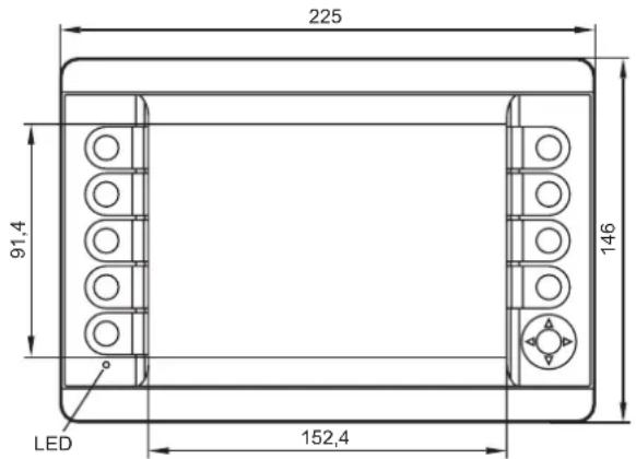
| Format 15:9 (wide VGA), 152.4 x 91.4 m |
| Resolution 800 x 480 pixels |
| Alignment horizontal |
| Surface glass with anti-glare coating |
| Colours 262.144 (18 bits) |
| Background illumination LED (lifetime ≥ 5 |
| Brightness ≥ 400 cd/m2, typically 500 cd/ |
| Contrast ratio ≥ 500:1, typically 600:1 |
| Character sets can be uploaded individua |
display for controlling, parameter-setting and operation of mobile machines and plants
m, 7" diagonal
(0,000 h)
m^2
(adjustable 0...100%, increments 1%)
Mechanical data
Mounting variants
Dimensions (W x H x D)
Cutout for panel mounting (W x H)
Housing material
Pushbuttons
Rocker switch
Background illumination operating elements
Protection rating
Operating temperature
Storage temperature
Weight
ally and is freely scalable
preinstalled: ifm ISO fonts with vehicle-specific symbols, Arial, Courier
panel mounting with mounting frame surface mounting with RAM ^® mount system (mounting accessories not included)
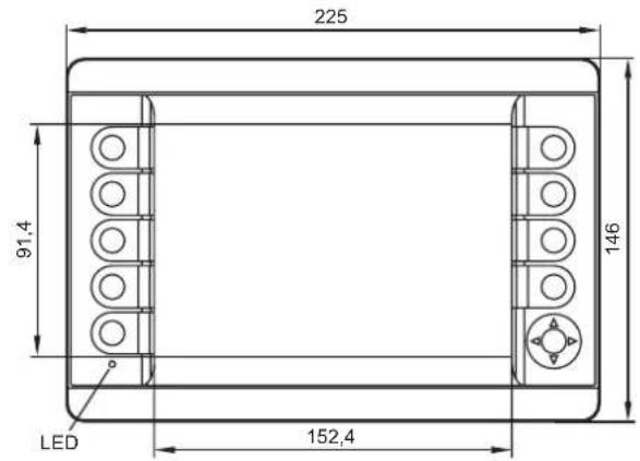
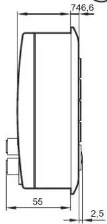
225 x 146 x 64.5 mm
183 ± 0.5 × 136 ± 0.5 mm
die-cast aluminium housing, powder coating (RAL 9005)
9 function keys (silicone keyboard) with tactile feedback freely programmable (softkey function) lifetime ≥ 1,000,000 activations
cursor function (up, down, left, right) with tactile feedback and with central mechanical pushbutton lifetime ≥ 1,000,000 activations
LED (brightness adjustable)
IP 67 (with mounted connectors and/or protective caps)
-30...65°C
-30...80°C
approx. 1.5 kg
| CR1081 Technical data | |
| Electrical data | |
| Operating voltage 10...32 V DC | |
| Overvoltage detection | at U_B > 32 V |
| Overvoltage shutdown | at U_B > 34 V (hysteresis 1 V, i.e. switching on again at U_B < 33 V) |
| Undervoltage detection | at U_B < 10 V |
| Undervoltage shutdown | at U_B < 8 V (hysteresis 1 V, i.e. switching on again at U_B > 9 V) |
| Accuracy | 3 % FS |
| Current consumption 300 mA (without external load at 24 V DC) | |
| Short-circuit / reverse polarity protection electronic | |
| Processor MPC5121, 32 bits, 400 MHz | |
| Total memory 256-Mbyte RAM / 128-Mbyte flash / 1-Gbyte internal mass storage | |
| Memory allocation see system manual PDM360 NGwww.ifm.com → Data sheet direct: → CR1081 → Additional data | |
| Interfaces | |
| CAN 1...4 CAN interface 2.0 A/B, ISO 11898 | 50 Kbits/s...1 Mbit/s (default 125 Kbits/s)CANopen, CiA DS 301 version 4, CiA DS 401 version 1.4or SAE J 1939 or free protocol (Raw CAN)max. current load VBB_c ≤ 400 mA (protected by multi fuse) |
| Ethernet transmission rate 10/100 Mbits/s | |
| USB 2 x USB 2.0 full speed, transmission rate up to 12 Mbit/sUSB master operation (service and maintenance connection for keyboard, mouse etc.)output current per interface ≤ 500 mA | |
| Analogue video input - | |
| Input | confi gurabledigital for positive / negative sensor signalsanalogue 0...10, 0...32 V, 0...20 mA, ratiometric |
| Output digital, positive switching (high side) | supply via terminal 30 |
| Characteristics of the input | Resolution 8 bits |
| Accuracy ± 3 % FS | |
| Current input 0...20 mA | Input resistance 390 Ω |
| Input frequency 10 Hz | |
| Voltage input 0...10 V | Input resistance 65.6 kΩ |
| Input frequency 10 Hz | |
| Voltage input 0...32 V | Input resistance 50.7 kΩ |
| Input frequency 10 Hz | |
| Voltage input ratiometric | Input resistance 50.7 kΩ |
| Input frequency 10 Hz | |
| Digital input | Input resistance 3.2 kΩ |
| Input frequency 10 Hz | |
| Switch-on level > 0.7 U_B | |
| Switch-off level < 0.3 U_B | |
| Characteristics of the output | Switching voltage 10...32 V DC |
| Switching current ≤ 1 A | |
| Free-wheeling diodes integrated | |
| Software/programming | |
| Operating system | Embedded Linux 2.6 |
| Programming system | CODESYS version 2.3 or CODESYS from version 3.5 SP8 (IEC 61131-3) |
| Graphic functions | via integrated target visualisation |
ifm electronic gmbh • Friedrichstraße 1 • 45128 Essen
We reserve the right to make technical alterations without prior notice! 12.01.2018CR1081 / page 2
| CR1081 Technical data | |||
| Other features | |||
| Acoustic signal output integrated buzzer | tone duration and pitch programmable | ||
| Temperature monitoring 2 integrated sensors for measuring the temperature inside the housing | |||
| Brightness adaptation light sensor in the front of the device to adapt the brightness of the display and the operating elements | |||
| Clock / Battery real-time clock (RTC), battery buffered / CR2032 (3 V, 230 mAh) | |||
| Status LED RGB LED, colours and states programmable by means of the application software | |||
| Operating states (preset) | Colour Status Description | ||
| - permanently off no operating voltage | |||
| green 5 Hz boot process application | |||
| red | 2 Hz application is running with an error (RUN with error) | ||
| red/orange | 2 Hz colour change | overtemperature/undertemperature, device is in reset until temperature in normal range | |
| orange | 5 Hz boot process system recovery/update | ||
| 2 Hz system recovery/update running | |||
| briefly on | System reset | ||
| Test standards and regulations | |||
| CE marking | EN 61000-6-2 Electromagnetic compatibility (EMC) Noise immunity | ||
| EN 61000-6-4 Electromagnetic compatibility (EMC) Emission standard | |||
| E1 marking | UN/ECE-R10 Emissions Noise immunity with 100 V/m | ||
| Electrical tests | ISO 7637-2 Pulse 1, severity level: IV; function state C Pulse 2a, severity level: IV; function state A Pulse 2b, severity level: IV; function state C Pulse 3a, severity level: IV; function state A Pulse 3b, severity level: IV; function state A Pulse 4, severity level: IV; function state A Pulse 5, severity level: III; function state C data valid for the 24V system | ||
| Climatic tests | EN 60068-2-30 Damp heat, cyclic upper temperature 55°C, number of cycles: 6 | ||
| EN 60068-2-78 Damp heat, constant test temperature 40°C / 93% RH, test duration: 21 days | |||
| EN 60068-2-52 Salt spray test severity level 3 (motor vehicle) | |||
| Mechanical tests ISO 16750-3 | Test VII; Vibration, random mounting location: vehicle body | ||
| EN 60068-2-6 Vibration, sinusoidal 10...500 Hz; 0.72 mm/10 g; 10 cycles/axis | |||
| ISO 16750-3 Bumps 30 r/6 ms; 24,000 shocks | |||
| Tests for railway applications | EN 50155 clause 12.2 mechanical/climatic tests | ||
| EN 50121-3-2 EMC noise emission and noise immunity | |||
| additional information on request | |||
ifm electronic gmbh • Friedrichstraße 1 • 45128 Essen
We reserve the right to make technical alterations without prior notice! 12.01.2018CR1081 / page 3
CR1081 Technical data
Back of the unit
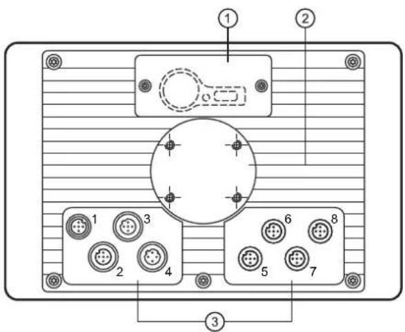
1: Service cover for USB connection, battery and watchdog reset
2: Locator for RAM ^® mount system and mounting frame
3: M12 connector (fig. shows max. number of connectors)
M12 connector
| 1 2, 5, 6, 7, 8 3 4 | |||
| ConnectorA-coded, 5 poles | SocketA-coded, 5 poles | SocketB-coded, 5 poles | SocketD-coded, 4 poles |
 |  |  |  |
Wiring
| (1) Supply, input/output (2) CAN1 | |||
| 1 | 10...32 V DC (clamp 30) (IN) | 1 | Shield |
| 2 | IN | 2 | VBBc (OUT) |
| 3 | GND (clamp 31) (IN) | 3 | CAN1_GND (OUT) |
| 4 | OUT | 4 | CAN1_H |
| 5 | 10...32 V DC (clamp 15) (IN) | 5 | CAN1_L |
| (3) USB (4) Ethernet | |||
| 1 | +5 V DC | 1 | TxD+ |
| 2 | -Data | 2 | RxD+ |
| 3 | +Data | 3 | TxD- |
| 4 | ID | 4 | RxD- |
| 5 | GND | Housing = screen | |
| (5) CAN2 (6) CAN3/4 | |||
| 1 | Shield | 1 | CAN3_H |
| 2 | VBBc(OUT) | 2 | CAN3_L |
| 3 | CAN2_GND (OUT) | 3 | CAN3/4_GND (OUT) |
| 4 | CAN2_H | 4 | CAN4_H |
| 5 | CAN2_L | 5 | CAN4_L |
| (7) N/A (8) N/A | |||
| 1 | 1 | ||
| 2 | 2 | ||
| 3 | 3 | ||
| 4 | 4 | ||
| 5 | 5 | ||
7.3 CR1082
CR1082
Process and dialogue module PDM360 NG
7" colour display, touch screen
9 freely programmable backlit function keys
rocker switch with pushbutton
analogue video input
1 input / 1 output
10...32 V DC
CE
E1
Technical data Programmable graphic
| Display |
| Display TFT LCD colour display |
| Format 15:9 (wide VGA), 152.4 x 91.4 m |
| Resolution 800 x 480 pixels |
| Alignment horizontal |
| Surface glass with anti-glare coating |
| Colours 262.144 (18 bits) |
| Background illumination LED (lifetime ≥ 5 |
| Brightness ≥ 400 cd/m2, typically 500 cd/ |
| Contrast ratio ≥ 500:1, typically 600:1 |
| Character sets can be uploaded individua |
| Touch screen |
| Mechanical data |
| Mounting variants |
| Dimensions (W x H x D) |
| Cutout for panel mounting (W x H) |
| Housing material |
| Pushbuttons |
| Rocker switch |
| Background illumination operating elements |
| Protection rating |
| Operating temperature |
| Storage temperature |
| Weight |
display for controlling, parameter-setting and operation of mobile machines and plants
| m, 7" diagonal |
| (0,000 h) |
| m^2 (adjustable 0...100%, increments 1%) |
| ally and is freely scalablepreinstalled: ifm ISO fonts with vehicle-specific symbols, Arial, Courier |
| 5-wire, resistiveInput tool: finger |
| panel mounting with mounting framesurface mounting with RAM®mount system(mounting accessories not included) |
| 225 x 146 x 62 mm |
| 183 ± 0.5 x 136 ± 0.5 mm |
| die-cast aluminium housing, powder coating (RAL 9005) |
| 9 function keys (silicone keyboard) with tactile feedbackfreely programmable (softkey function)lifetime ≥ 1,000,000 activations |
| cursor function (up, down, left, right) with tactile feedback and withcentral mechanical pushbuttonlifetime ≥ 1,000,000 activations |
| LED (brightness adjustable) |
| IP 67 (with mounted connectors and/or protective caps) |
| -30...65°C |
| -30...80°C |
| approx. 1.5 kg |
ifm electronic gmbh • Friedrichstraße 1 • 45128 Essen
We reserve the right to make technical alterations without prior notice! 12.01.2018CR1082 / page 1
| CR1082 Technical data | |
| Electrical data | |
| Operating voltage 10...32 V DC | |
| Overvoltage detection | at U_B > 32 V |
| Overvoltage shutdown | at U_B > 34 V (hysteresis 1 V, i.e. switching on again at U_B < 33 V) |
| Undervoltage detection | at U_B < 10 V |
| Undervoltage shutdown | at U_B < 8 V (hysteresis 1 V, i.e. switching on again at U_B > 9 V) |
| Accuracy | 3 % FS |
| Current consumption 300 mA (without external load at 24 V DC) | |
| Short-circuit / reverse polarity protection electronic | |
| Processor MPC5121, 32 bits, 400 MHz | |
| Total memory 256-Mbyte RAM / 128-Mbyte flash / 1-Gbyte internal mass storage | |
| Memory allocation see system manual PDM360 NG | |
| Interfaces | |
| CAN 1...4 CAN interface 2.0 A/B, ISO 11898 | 50 Kbits/s...1 Mbit/s (default 125 Kbits/s)CANopen, CiA DS 301 version 4, CiA DS 401 version 1.4or SAE J 1939 or free protocol (Raw CAN)max. current load VBB_c ≤ 400 mA (protected by multi fuse) |
| Ethernet transmission rate 10/100 Mbits/s | |
| USB 2 x USB 2.0 full speed, transmission rate up to 12 Mbit/s | USB master operation (service and maintenance connection for keyboard, mouse etc.)output current per interface ≤ 500 mA |
| Analogue video input 2 FBAS inputs, 1 Vss, 75 ohms (inputs selectable)supported video standards: PAL and NTSCcable length: ≤ 30 m | |
| Input | configurabledigital for positive / negative sensor signalsanalogue 0...10, 0...32 V, 0...20 mA, ratiometric |
| Output | digital, positive switching (high side)supply via terminal 30 |
| Characteristics of the input | Resolution 8 bits |
| Accuracy ± 3 % FS | |
| Current input 0...20 mA | Input resistance 390 Ω |
| Input frequency 10 Hz | |
| Voltage input 0...10 V | Input resistance 65.6 kΩ |
| Input frequency 10 Hz | |
| Voltage input 0...32 V | Input resistance 50.7 kΩ |
| Input frequency 10 Hz | |
| Voltage input ratiometric | Input resistance 50.7 kΩ |
| Input frequency 10 Hz | |
| Digital input | Input resistance 3.2 kΩ |
| Input frequency 10 Hz | |
| Switch-on level > 0.7 U_B | |
| Switch-off level < 0.3 U_B | |
| Characteristics of the output | Switching voltage 10...32 V DC |
| Switching current ≤ 1 A | |
| Free-wheeling diodes integrated | |
ifm electronic gmbh • Friedrichstraße 1 • 45128 Essen
We reserve the right to make technical alterations without prior notice! 12.01.2018CR1082 / page 2
| CR1082 Technical data | |||
| Software/programming | |||
| Operating system Embedded Linux 2.6 | |||
| Programming system CODESYS version | 2.3 or CODESYS from version 3.5 SP8 (IEC 61131-3) | ||
| Graphic functions via integrated target visualisation | |||
| Other features | |||
| Acoustic signal output integrated buzzer, tone duration and pitch programmable | |||
| Temperature monitoring 2 integrated sensors for measuring the temperature inside the housing | |||
| Brightness adaptation light sensor in the front of the device to adapt the brightness of the display and the operating elements | |||
| Clock / Battery real-time clock (RTC), battery buffered / CR2032 (3 V, 230 mAh) | |||
| Status LED RGB LED, colours and states programmable by means of the application software | |||
| Operating states (preset) | |||
| Colour Status | Description | ||
| - | permanently off | no operating voltage | |
| green | 5 Hz | boot process application | |
| 2 Hz | application running (RUN) or set-up running | ||
| permanently on | application has stopped (STOP) or no project available | ||
| red | 2 Hz | application is running with an error (RUN with error) | |
| permanently on | system error (fatal error), device is in reset (e.g. internal voltage error) | ||
| red/orange | 2 Hz colour change | overtemperature/undertemperature, device is in reset until temperature in normal range | |
| orange | 5 Hz | boot process system recovery/update | |
| 2 Hz | system recovery/update running | ||
| briefly on | System reset | ||
ifm electronic gmbh • Friedrichstraße 1 • 45128 Essen
We reserve the right to make technical alterations without prior notice! 12.01.2018CR1082 / page 3
| CR1082 Technical data | |
| Test standards and regulations | |
| CE marking EN 61000-6-2 Electromagnetic compatibility (EMC) | Noise immunity |
| EN 61000-6-4 Electromagnetic compatibility (EMC)Emission standard | |
| E1 marking UN/ECE-R10 Emissions | Noise immunity with 100 V/mAnalogue video input 30 V/m |
| Electrical tests ISO 7637-2 Pulse 1, severity level: IV; function state C | Pulse 2a, severity level: IV; function state APulse 2b, severity level: IV; function state CPulse 3a, severity level: IV; function state APulse 3b, severity level: IV; function state APulse 4, severity level: IV; function state APulse 5, severity level: III; function state Cdata valid for the 24V system |
| Climatic tests EN 60068-2-30 Damp heat, cyclic | upper temperature 55°C, number of cycles: 6 |
| EN 60068-2-78 Damp heat, constanttest temperature 40°C / 93% RH,test duration: 21 days | |
| EN 60068-2-52 Salt spray testseverity level 3 (motor vehicle) | |
| Mechanical tests ISO 16750-3 Test VII; Vibration, random | mounting location: vehicle body |
| EN 60068-2-6 Vibration, sinusoidal10...500 Hz; 0.72 mm/10 g; 10 cycles/axis | |
| ISO 16750-3 Bumps30 r/6 ms; 24,000 shocks | |
| Tests for railway applications | EN 50155 clause 12.2 mechanical/climatic tests |
| EN 50121-3-2 EMC noise emission and noise immunity | |
| additional information on request | |
ifm electronic gmbh • Friedrichstraße 1 • 45128 Essen
We reserve the right to make technical alterations without prior notice! 12.01.2018CR1082 / page 4
CR1082 Technical data
Back of the unit
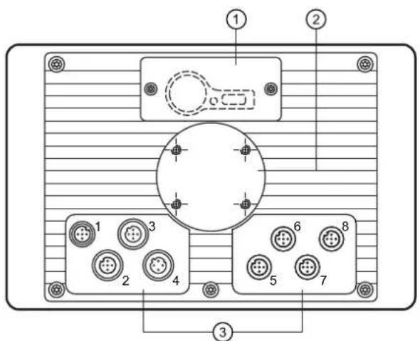
M12 connector
1: Service cover for USB connection, battery and watchdog reset
2: Locator for RAM ^® mount system and mounting frame
3: M12 connector (fig. shows max. number of connectors)
| 1 2, 5, 6, 7, 8 3 4 | |||
| ConnectorA-coded, 5 poles | SocketA-coded, 5 poles | SocketB-coded, 5 poles | SocketD-coded, 4 poles |
 |  |  |  |
Wiring
| (1) Supply, input/output (2) CAN1 | |||
| 1 | 10...32 V DC (clamp 30) (IN) | 1 | Shield |
| 2 | IN | 2 | VBBc (OUT) |
| 3 | GND (clamp 31) (IN) | 3 | CAN1_GND (OUT) |
| 4 | OUT | 4 | CAN1_H |
| 5 | 10...32 V DC (clamp 15) (IN) | 5 | CAN1_L |
| (3) USB (4) Ethernet | |||
| 1 | +5 V DC | 1 | TxD+ |
| 2 | -Data | 2 | RxD+ |
| 3 | +Data | 3 | TxD- |
| 4 | ID | 4 | RxD- |
| 5 | GND | Housing = screen | |
| (5) CAN2 (6) CAN3/4 | |||
| 1 | Shield | 1 | CAN3_H |
| 2 | VBBc(OUT) | 2 | CAN3_L |
| 3 | CAN2_GND (OUT) | 3 | CAN3/4_GND (OUT) |
| 4 | CAN2_H | 4 | CAN4_H |
| 5 | CAN2_L | 5 | CAN4_L |
| (7) Analogue video input (8) N/A | |||
| 1 | Shield | 1 | |
| 2 | GND (video 2) | 2 | |
| 3 | GND (video 1) | 3 | |
| 4 | FBAS1 (video 1) | 4 | |
| 5 | FBAS2 (video 2) | 5 | |
7.4 CR1084
CR1084
Process and dialogue module PDM360 NG
7" colour display
9 freely programmable backlit function keys
encoder with pushbutton
analogue video input
1 input / 1 output
10...32 V DC
CE
E1
Technical data Programmable graphic
| Display |
| Display TFT LCD colour display |
| Format 15:9 (wide VGA), 152.4 x 91.4 m |
| Resolution 800 x 480 pixels |
| Alignment horizontal |
| Surface glass with anti-glare coating |
| Colours 262.144 (18 bits) |
| Background illumination LED (lifetime ≥ 5 |
| Brightness ≥ 400 cd/m2, typically 500 cd/m |
| Contrast ratio ≥ 500:1, typically 600:1 |
| Character sets can be uploaded individua |
| Mechanical data |
| Mounting variants |
| Dimensions (W x H x D) |
| Cutout for panel mounting (W x H) |
| Housing material |
| Pushbuttons |
| Encoder |
| Background illumination operating elements |
| Protection rating |
| Operating temperature |
| Storage temperature |
| Weight |
display for controlling, parameter-setting and operation of mobile machines and plants
| n, 7" diagonal |
| 0,000 h) |
| n^2 (adjustable 0...100%, increments 1%) |
| Ily and is freely scalable preinstalled: ifm ISO fonts with vehicle-specific symbols, Arial, Courier |
| panel mounting with mounting frame surface mounting with RAM®mount system (mounting accessories not included) |
| 225 x 146 x 80 mm |
| 183 ± 0.5 x 136 ± 0.5 mm |
| die-cast aluminium housing, powder coating (RAL 9005) |
| 9 function keys (silicone keyboard) with tactile feedback freely programmable (softkey function) lifetime ≥ 1,000,000 activations |
| with photoelectric rotation detection, latching and central mechanical pushbutton lifetime ≥ 1,000,000 cycles |
| LED (brightness adjustable) |
| IP 65 (with mounted connectors and/or protective caps) |
| -30...65°C |
| -30...80°C |
| approx. 1.5 kg |
ifm electronic gmbh • Friedrichstraße 1 • 45128 Essen
We reserve the right to make technical alterations without prior notice! 12.01.2018CR1084 / page 1
| CR1084 Technical data | |
| Electrical data | |
| Operating voltage 10...32 V DC | |
| Overvoltage detection | at U_B > 32 V |
| Overvoltage shutdown | at U_B > 34 V (hysteresis 1 V, i.e. switching on again at U_B < 33 V) |
| Undervoltage detection | at U_B < 10 V |
| Undervoltage shutdown | at U_B < 8 V (hysteresis 1 V, i.e. switching on again at U_B > 9 V) |
| Accuracy | 3 % FS |
| Current consumption 300 mA (without external load at 24 V DC) | |
| Short-circuit / reverse polarity protection electronic | |
| Processor MPC5121, 32 bits, 400 MHz | |
| Total memory 256-Mbyte RAM / 128-Mbyte flash / 1-Gbyte internal mass storage | |
| Memory allocation see system manual PDM360 NGwww.ifm.com → Data sheet direct: → CR1084 → Additional data | |
| Interfaces | |
| CAN 1...4 CAN interface 2.0 A/B, ISO 11898 | 50 Kbits/s...1 Mbit/s (default 125 Kbits/s)CANopen, CiA DS 301 version 4, CiA DS 401 version 1.4or SAE J 1939 or free protocol (Raw CAN)max. current load VBB_c ≤ 400 mA (protected by multi fuse) |
| Ethernet transmission rate 10/100 Mbits/s | |
| USB 2 x USB 2.0 full speed, transmission rate up to 12 Mbit/sUSB master operation (service and maintenance connection for keyboard, mouse etc.)output current per interface ≤ 500 mA | |
| Analogue video input 2 FBAS inputs, 1 Vss, 75 ohms (inputs selectable)supported video standards: PAL and NTSCcable length: ≤ 30 m | |
| Input | configurabledigital for positive / negative sensor signalsanalogue 0...10, 0...32 V, 0...20 mA, ratiometric |
| Output | digital, positive switching (high side), supply via terminal 30 |
| Characteristics of the input | Resolution 8 bits |
| Accuracy ± 3 % FS | |
| Current input 0...20 mA | Input resistance 390 Ω |
| Input frequency 10 Hz | |
| Voltage input 0...10 V | Input resistance 65.6 kΩ |
| Input frequency 10 Hz | |
| Voltage input 0...32 V | Input resistance 50.7 kΩ |
| Input frequency 10 Hz | |
| Voltage input ratiometric | Input resistance 50.7 kΩ |
| Input frequency 10 Hz | |
| Digital input | Input resistance 3.2 kΩ |
| Input frequency 10 Hz | |
| Switch-on level > 0.7 U_B | |
| Switch-off level < 0.3 U_i | |
| Characteristics of the output | Switching voltage 10...32 V DC |
| Switching current ≤ 1 A | |
| Free-wheeling diodes integrated | |
ifm electronic gmbh • Friedrichstraße 1 • 45128 Essen
We reserve the right to make technical alterations without prior notice! 12.01.2018CR1084 / page 2
CR1084 Technical data
Software/programming
Operating system Embedded Linux 2.6
Programming system CODESYS version
Graphic functions via integrated target vi
Other features
Acoustic signal output integrated buzzer,
Temperature monitoring 2 integrated ser
Brightness adaptation light sensor in the
Clock / Battery real-time clock (RTC), ba
Status LED RGB LED, colours and state
Operating states (preset)
2.3 or CODESYS from version 3.5 SP8 (IEC 61131-3)
sualisation
tone duration and pitch programmable
ors for measuring the temperature inside the housing
front of the device to adapt the brightness of the display and the operating elements
tery buff ered / CR2032 (3 V, 230 mAh)
programmable by means of the application software
| Colour Status | Description | |
| - | permanently off | no operating voltage |
| green | 5 Hz | boot process application |
| 2 Hz | application running (RUN) or set-up running | |
| permanently on | application has stopped (STOP) or no project available | |
| red | 2 Hz | application is running with an error (RUN with error) |
| permanently on | system error (fatal error), device is in reset (e.g. internal voltage error) | |
| red/orange | 2 Hz colour change | overtemperature/undertemperature, device is in reset until temperature in normal range |
| orange | 5 Hz | boot process system recovery/update |
| 2 Hz | system recovery/update running | |
| briefly on | System reset |
| CR1084 Technical data | |
| Test standards and regulations | |
| CE marking EN 61000-6-2 Electromagnetic compatibility (EMC) | Immunity |
| EN 61000-6-4 Electromagnetic compatibility (EMC)Emission standard | |
| E1 marking UN/ECE-R10 Emissions | Noise immunity with 100 V/mAnalogue video input 30 V/m |
| Electrical tests ISO 7637-2 Pulse 1, severity level: IV; function state C | Pulse 2a, severity level: IV; function state APulse 2b, severity level: IV; function state CPulse 3a, severity level: IV; function state APulse 3b, severity level: IV; function state APulse 4, severity level: IV; function state APulse 5, severity level: III; function state Cdata valid for the 24V system |
| Climatic tests EN 60068-2-30 Damp heat, cyclic | upper temperature 55°C, number of cycles: 6 |
| EN 60068-2-78 Damp heat, steady statetest temperature 40°C / 93% RH,test duration: 21 days | |
| EN 60068-2-52 Salt spray testseverity level 3 (vehicle) | |
| Mechanical tests ISO 16750-3 Test VII; Vibration, random | mounting location: vehicle body |
| EN 60068-2-6 Vibration, sinusoidal10...500 Hz; 0.72 mm/10 g; 10 cycles/axis | |
| ISO 16750-3 Bumps30 g/6 ms; 24,000 shocks | |
| Tests for railway applications | EN 50155 clause 12.2 mechanical/climatic tests |
| EN 50121-3-2 EMC noise emission and noise immunity | |
| additional information on request | |
ifm electronic gmbh • Friedrichstraße 1 • 45128 Essen
We reserve the right to make technical alterations without prior notice! 12.01.2018CR1084 / page 4
CR1084 Technical data
Back of the unit
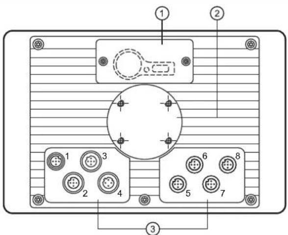
1: Service cover for USB connection, battery and watchdog reset
2: Locator for RAM ^® mount system and mounting frame
3: M12 connector (fig. shows max. number of connectors)
M12 connector
| 1 2, 5, 6, 7, 8 3 4 | |||
| ConnectorA-coded, 5 poles | SocketA-coded, 5 poles | SocketB-coded, 5 poles | SocketD-coded, 4 poles |
 |  |  |  |
Wiring
| (1) Supply, input/output (2) CAN1 | |||
| 1 | 10...32 V DC (clamp 30) (IN) | 1 | Shield |
| 2 | IN | 2 | VBBc (OUT) |
| 3 | GND (clamp 31) (IN) | 3 | CAN1_GND (OUT) |
| 4 | OUT | 4 | CAN1_H |
| 5 | 10...32 V DC (clamp 15) (IN) | 5 | CAN1_L |
(3) USB (4) Ethernet
| 1 | +5 V DC |
| 2 | -Data |
| 3 | +Data |
| 4 | ID |
| 5 | GND |
| 1 | TxD+ |
| 2 | RxD+ |
| 3 | TxD- |
| 4 | RxD- |
| Housing = screen | |
(5) CAN2 (6) CAN3/4
| 1 | Shield |
| 2 | VBBc(OUT) |
| 3 | CAN2_GND (OUT) |
| 4 | CAN2_H |
| 5 | CAN2_L |
| 1 | CAN3_H |
| 2 | CAN3_L |
| 3 | CAN3/4_GND (OUT) |
| 4 | CAN4_H |
| 5 | CAN4_L |
(7) Analogue video input (8) N/A
| 1 | Shield |
| 2 | GND (video 2) |
| 3 | GND (video 1) |
| 4 | FBAS1 (video 1) |
| 5 | FBAS2 (video 2) |
| 1 | |
| 2 | |
| 3 | |
| 4 | |
| 5 | |
7.5 CR1085
CR1085
Process and dialogue module PDM360 NG
7" colour display
9 freely programmable backlit function keys
rocker switch with pushbutton
analogue video input
1 input / 1 output
10...32 V DC
CE
E1
Technical data Programmable graphic
| Display |
| Display TFT LCD colour display |
| Format 15:9 (wide VGA), 152.4 x 91.4 m |
| Resolution 800 x 480 pixels |
| Alignment horizontal |
| Surface glass with anti-glare coating |
| Colours 262.144 (18 bits) |
| Background illumination LED (lifetime ≥ 5 |
| Brightness ≥ 400 cd/m2, typically 500 cd/ |
| Contrast ratio ≥ 500:1, typically 600:1 |
| Character sets can be uploaded individua |
| Mechanical data |
| Mounting variants |
| Dimensions (W x H x D) |
| Cutout for panel mounting (W x H) |
| Housing material |
| Pushbuttons |
| Rocker switch |
| Background illumination operating elements |
| Protection rating |
| Operating temperature |
| Storage temperature |
| Weight |
display for controlling, parameter-setting and operation of mobile machines and plants
| m, 7" diagonal |
| 60,000 h) |
| m2(adjustable 0...100%, increments 1%) |
| ally and is freely scalable preinstalled: ifm ISO fonts with vehicle-specific symbols, Arial, Courier |
| panel mounting with mounting frame surface mounting with RAM® mount system (mounting accessories not included) |
| 225 x 146 x 64.5 mm |
| 183 ± 0.5 x 136 ± 0.5 mm |
| die-cast aluminium housing, powder coating (RAL 9005) |
| 9 function keys (silicone keyboard) with tactile feedback freely programmable (softkey function) lifetime ≥ 1,000,000 activations |
| cursor function (up, down, left, right) with tactile feedback and with central mechanical pushbutton lifetime ≥ 1,000,000 activations |
| LED (brightness adjustable) |
| IP 67 (with mounted connectors and/or protective caps) |
| -30...65°C |
| -30...80°C |
| approx. 1.5 kg |
ifm electronic gmbh • Friedrichstraße 1 • 45128 Essen
We reserve the right to make technical alterations without prior notice! 12.01.2018CR1085 / page 1
| CR1085 Technical data | |
| Electrical data | |
| Operating voltage 10...32 V DC | |
| Overvoltage detection | at U_B > 32 V |
| Overvoltage shutdown | at U_B > 34 V (hysteresis 1 V, i.e. switching on again at U_B < 33 V) |
| Undervoltage detection | at U_B < 10 V |
| Undervoltage shutdown | at U_B < 8 V (hysteresis 1 V, i.e. switching on again at U_B > 9 V) |
| Accuracy | 3 % FS |
| Current consumption 300 mA (without external load at 24 V DC) | |
| Short-circuit / reverse polarity protection electronic | |
| Processor MPC5121, 32 bits, 400 MHz | |
| Total memory 256-Mbyte RAM / 128-Mbyte flash / 1-Gbyte internal mass storage | |
| Memory allocation see system manual PDM360 NGwww.ifm.com → Data sheet direct: → CR1085 → Additional data | |
| Interfaces | |
| CAN 1...4 CAN interface 2.0 A/B, ISO 11898 | 50 Kbits/s...1 Mbit/s (default 125 Kbits/s)CANopen, CiA DS 301 version 4, CiA DS 401 version 1.4or SAE J 1939 or free protocol (Raw CAN)max. current load VBB≤ 400 mA (protected by multi fuse) |
| Ethernet transmission rate 10/100 Mbits/s | |
| USB 2 x USB 2.0 full speed, transmission rate up to 12 Mbit/sUSB master operation (service and maintenance connection for keyboard, mouse etc.)output current per interface ≤ 500 mA | |
| Analogue video input 2 FBAS inputs, 1 Vss, 75 ohms (inputs selectable)supported video standards: PAL and NTSC, cable length: ≤ 30 m | |
| Input | confi gurabledigital for positive / negative sensor signalsanalogue 0...10, 0...32 V, 0...20 mA, ratiometric |
| Output digital, positive switching (high side) | supply via terminal 30 |
| Characteristics of the input | Resolution 8 bits |
| Accuracy ± 3 % FS | |
| Current input 0...20 mA | Input resistance 390 Ω |
| Input frequency 10 Hz | |
| Voltage input 0...10 V | Input resistance 65.6 kΩ |
| Input frequency 10 Hz | |
| Voltage input 0...32 V | Input resistance 50.7 kΩ |
| Input frequency 10 Hz | |
| Voltage input ratiometric | Input resistance 50.7 kΩ |
| Input frequency 10 Hz | |
| Digital input | Input resistance 3.2 kΩ |
| Input frequency 10 Hz | |
| Switch-on level > 0.7 U_s | |
| Switch-off level < 0.3 U_h | |
| Characteristics of the output | Switching voltage 10...32 V DC |
| Switching current ≤ 1 A | |
| Free-wheeling diodes integrated | |
ifm electronic gmbh • Friedrichstraße 1 • 45128 Essen
We reserve the right to make technical alterations without prior notice! 12.01.2018CR1085 / page 2
| CR1085 Technical data | |||
| Software/programming | |||
| Operating system Embedded Linux 2.6 | |||
| Programming system CODESYS version | 2.3 or CODESYS from version 3.5 SP8 (IEC 61131-3) | ||
| Graphic functions via integrated target visualisation | |||
| Other features | |||
| Acoustic signal output integrated buzzer | tone duration and pitch programmable | ||
| Temperature monitoring 2 integrated sensors for measuring the temperature inside the housing | |||
| Brightness adaptation light sensor in the front of the device to adapt the brightness of the display and the operating elements | |||
| Clock / Battery real-time clock (RTC), battery buff ered / CR2032 (3 V, 230 mAh) | |||
| Status LED RGB LED, colours and states programmable by means of the application software | |||
| Operating states (preset) | |||
| Colour Status | Description | ||
| - | permanently off | no operating voltage | |
| green | 5 Hz | boot process application | |
| 2 Hz | application running (RUN) or set-up running | ||
| permanently on | application has stopped (STOP) or no project available | ||
| red | 2 Hz | application is running with an error (RUN with error) | |
| permanently on | system error (fatal error), device is in reset (e.g. internal voltage error) | ||
| red/orange | 2 Hz colour change | overtemperature/undertemperature, device is in reset until temperature in normal range | |
| orange | 5 Hz | boot process system recovery/update | |
| 2 Hz | system recovery/update running | ||
| briefly on | System reset | ||
ifm electronic gmbh • Friedrichstraße 1 • 45128 Essen
We reserve the right to make technical alterations without prior notice! 12.01.2018CR1085 / page 3
| CR1085 Technical data | |
| Test standards and regulations | |
| CE marking EN 61000-6-2 Electromagnetic compatibility (EMC) | Noise immunity |
| EN 61000-6-4 Electromagnetic compatibility (EMC)Emission standard | |
| E1 marking UN/ECE-R10 Emissions | Noise immunity with 100 V/mAnalogue video input 30 V/m |
| Electrical tests ISO 7637-2 Pulse 1, severity level: IV; function state C | Pulse 2a, severity level: IV; function state APulse 2b, severity level: IV; function state CPulse 3a, severity level: IV; function state APulse 3b, severity level: IV; function state APulse 4, severity level: IV; function state APulse 5, severity level: III; function state Cdata valid for the 24V system |
| Climatic tests EN 60068-2-30 Damp heat, cyclic | upper temperature 55°C, number of cycles: 6 |
| EN 60068-2-78 Damp heat, constanttest temperature 40°C / 93% RH,test duration: 21 days | |
| EN 60068-2-52 Salt spray testseverity level 3 (motor vehicle) | |
| Mechanical tests ISO 16750-3 Test VII; Vibration, random | mounting location: vehicle body |
| EN 60068-2-6 Vibration, sinusoidal10...500 Hz; 0.72 mm/10 g; 10 cycles/axis | |
| ISO 16750-3 Bumps30 r/6 ms; 24,000 shocks | |
| Tests for railway applications | EN 50155 clause 12.2 mechanical/climatic tests |
| EN 50121-3-2 EMC noise emission and noise immunity | |
| additional information on request | |
ifm electronic gmbh • Friedrichstraße 1 • 45128 Essen
We reserve the right to make technical alterations without prior notice! 12.01.2018CR1085 / page 4
CR1085 Technical data
Back of the unit
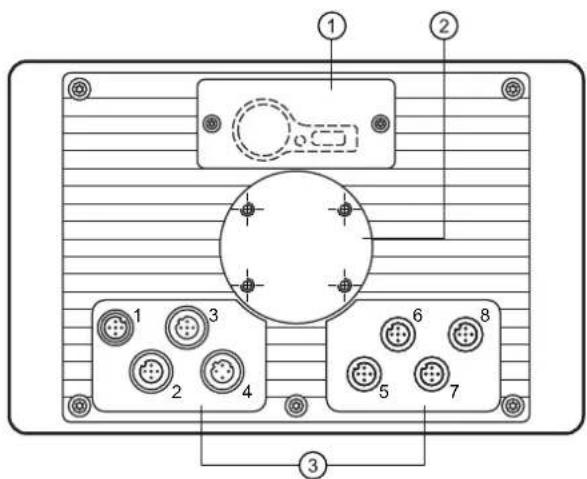
M12 connector
1: Service cover for USB connection, battery and watchdog reset
2: Locator for RAM ^® mount system and mounting frame
3: M12 connector (fig. shows max. number of connectors)
| 1 2, 5, 6, 7, 8 3 4 | |||
| ConnectorA-coded, 5 poles | SocketA-coded, 5 poles | SocketB-coded, 5 poles | SocketD-coded, 4 poles |
 |  |  |  |
Wiring
| (1) Supply, input/output (2) CAN1 | |||
| 1 | 10...32 V DC (clamp 30) (IN) | 1 | Shield |
| 2 | IN | 2 | VBBc (OUT) |
| 3 | GND (clamp 31) (IN) | 3 | CAN1_GND (OUT) |
| 4 | OUT | 4 | CAN1_H |
| 5 | 10...32 V DC (clamp 15) (IN) | 5 | CAN1_L |
| (3) USB (4) Ethernet | |||
| 1 | +5 V DC | 1 | TxD+ |
| 2 | -Data | 2 | RxD+ |
| 3 | +Data | 3 | TxD- |
| 4 | ID | 4 | RxD- |
| 5 | GND | Housing = screen | |
| (5) CAN2 (6) CAN3/4 | |||
| 1 | Shield | 1 | CAN3_H |
| 2 | VBBc(OUT) | 2 | CAN3_L |
| 3 | CAN2_GND (OUT) | 3 | CAN3/4_GND (OUT) |
| 4 | CAN2_H | 4 | CAN4_H |
| 5 | CAN2_L | 5 | CAN4_L |
| (7) Analogue video input (8) N/A | |||
| 1 | Shield | 1 | |
| 2 | GND (video 2) | 2 | |
| 3 | GND (video 1) | 3 | |
| 4 | FBAS1 (video 1) | 4 | |
| 5 | FBAS2 (video 2) | 5 | |
8 Maintenance, repair and disposal
8.1 Battery change
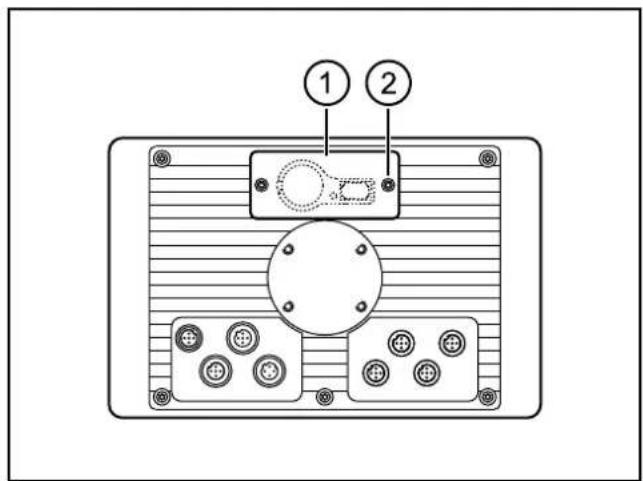
1: service cover
2: socket head screws
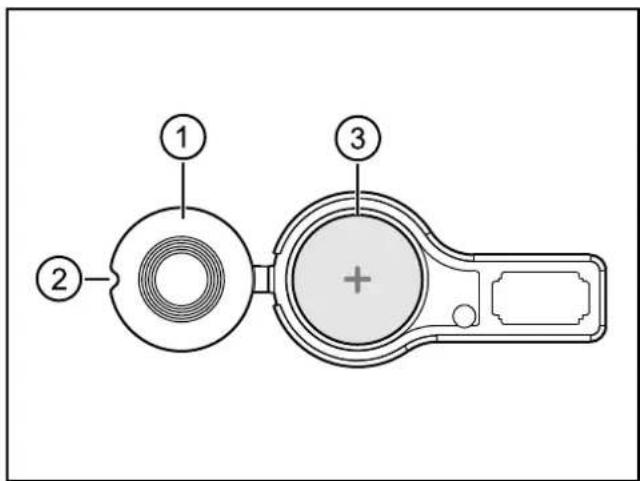
1: battery cover
2: indentation for opening
3: battery case
▶ Remove the service cover on the back of the unit.
(2 M3 socket head screws)
▶ Open the battery compartment using a pointed object (e.g. a screwdriver).
▶ Remove the battery and replace it with a new one.
Observe the polarity: Positive side up (see also marking on the cover)
Battery type ( 7 Technical data)
Disposal of used batteries ( 8.5 Disposal)
8.2 Cleaning the display surface

Unsuitable cleaning agents and chemicals can damage the display surface.
The following agents are not suited for cleaning the display:
- chemicals dissolving plastics such as methylated spirit, benzine, thinner, alcohol, acetone or ammonia.
• paper towels, crepe paper etc.
- abrasive cleaners
- polish or wax
▶ Clean the device from dirt using a soft, chemically untreated and dry cloth.
▶ In case of heavy dirt, use a damp cloth.

Micro-fibre cloths without chemical additives are recommended.
8.3 Cleaning the housing surface
▶ Disconnect the device.
▶ Clean the device from dirt using a soft, chemically untreated and dry cloth.
▶ In case of heavy dirt, use a damp cloth.
8.4 Repair
▶ The device must only be repaired by the manufacturer.
Observe the safety instructions ( 2.4 Tampering with the device)
8.5 Disposal
▶ Do not dispose of used batteries with household waste.
Dispose of used batteries in accordance with the national environmental regulations.
▶ Dispose of the device in accordance with the national environmental regulations.
9 Approvals / standards
Test standards and regulations ( 7 Technical data)
The EC declaration of conformity and approvals can be found at: www.ifm.com → data sheet search → e.g. CR1080 → Approvals
- Contents
- Licences and trademarks
- Validity of these instructions
- Preliminary note
- Symbols used
- Warning signs used
- WARNING
- CAUTION
- NOTE
- Safety instructions
- General
- Target group
- Electrical connection
- Tampering with the device
- Electromagnetic compatibility
- Functions and features
- Application example
- Overview of the common characteristics
- Distinctive features
- Installation
- Mounting accessory
- General installation instructions
- Locator for mounting accessories
- ATTENTION
- Orientation of the device with panel and surface mounting
- Light sensor
- Protective film for the touch screen (CR1082)
- Panel mounting using the mounting frame
- Mounting steps
- Mounting principle
- Procedure:
- Surface mounting with RAM ® mount system
- Mounting steps
- Electrical connection
- Connection accessories
- General electrical connection
- Cover all unused connectors
- Operating voltage and fuses
- Voltage supply of the switching output via clamp 30
- Ground connection
- Ethernet interface
- Ethernet cameras
- Analogue video inputs (only CR1082/84/85)
- USB interfaces
- USB connection via M12 connector
- Short-circuit protection
- USB connection behind the service cover
- Set-up
- General
- First steps
- Set-up
- Required documentation
- Technical data
- CR1080
- CR1080
- CR1080 Technical data
- CR1081
- CR1081
- CR1081 Technical data
- CR1082
- CR1082
- CR1082 Technical data
- CR1084
- CR1084
- CR1084 Technical data
- Software/programming
- Other features
- CR1085
- CR1085
- CR1085 Technical data
- Maintenance, repair and disposal
- Battery change
- Cleaning the display surface
- Cleaning the housing surface
- Repair
- Disposal
- Approvals / standards
Brand : IFM
Model : EC2110
Category : Dialogue and Process Module