RM-CA2 - Loudspeaker Sonifex - Free user manual and instructions
Find the device manual for free RM-CA2 Sonifex in PDF.


| Product Type | Powered Monitor Speaker |
| Brand | Sonifex |
| Model | RM-CA2 |
| Dimensions (W x H x D) | 19 x 1.75 x 8 inches (483 x 44 x 203 mm) |
| Weight | 5.5 kg (12.1 lbs) |
| Power Supply | AC 100-240V, 50/60 Hz, internal power supply |
| Power Consumption | 60W typical |
| Audio Inputs | Balanced XLR, unbalanced RCA, stereo 3.5mm jack |
| Frequency Response | 60 Hz - 20 kHz (±3 dB) |
| Amplifier Power | 2 x 30W RMS |
| Driver Size | 4 inch woofer, 1 inch tweeter |
| Enclosure Type | Bass reflex, ported |
| Controls | Volume knob, power switch, input selector |
| Mounting | 19-inch rack mount, 1U |
| Operating Temperature | 0°C to 40°C (32°F to 104°F) |
| Safety Features | Overload protection, thermal shutdown |
| Cleaning Instructions | Wipe with a soft, dry cloth; do not use liquids |
| Spare Parts Availability | Contact Sonifex for replacement drivers, amplifiers, and power supplies |
| Warranty | 2 years standard |
Frequently Asked Questions - RM-CA2 Sonifex
User questions about RM-CA2 Sonifex
0 question about this device. Answer the ones you know or ask your own.
Ask a new question about this device
Download the instructions for your Loudspeaker in PDF format for free! Find your manual RM-CA2 - Sonifex and take your electronic device back in hand. On this page are published all the documents necessary for the use of your device. RM-CA2 by Sonifex.
USER MANUAL RM-CA2 Sonifex

Confidence Monitors User Handbook
RM-CA2 Confidence Monitor, 2 LED Meters & 2 Analogue Stereo Inputs
RM-CAD8 Confidence Monitor, 2 LED Meters, 2 Analogue & 6 Digital Stereo Inputs

CONFIDENCE MONITORS USER HANDBOOK

natural_image
Abstract graphic with two stylized swords and a circular emblem (no text or symbols)This handbook is for use with the following product:
RM-CA2 Confidence Monitor, 2 LED Meters & 2 Analogue Stereo Inputs
RM-CAD8 Confidence Monitor, 2 LED Meters, 2 Analogue & 6 Digital Stereo Inputs
©Sonifex Ltd, 2009
All Rights Reserved
Revision 1.00, May 2009
Sonifex Ltd, 61, Station Road, Irthlingborough,
Northants, NN9 5QE, England.
Tel: +44 (0)1933 650 700
Fax: +44 (0)1933 650 726
Email: sales@sonifex.co.uk
Website: http://www.sonifex.co.uk
Information in this document is subject to change without notice and does not represent a commitment on the part of the vendor. Sonifex Ltd shall not be liable for any loss or damage whatsoever arising from the use of information or any error contained in this manual.
No part of this manual may be reproduced or transmitted in any form or by any means, electronic or mechanical, including photocopying, recording, information storage and retrieval systems, for any purpose other than the purchaser's personal use, without the express written permission of Sonifex Ltd. Unless otherwise noted, all names of companies, products and persons contained herein are part of a completely fictitious adaptation and are designed solely to document the use of Sonifex product.
Warranty i
Warranty and Liability i
Unpacking the Confidence Monitor iii
Returning the Warranty Card iii
Safety Information iv
Safety of Mains Operated Equipment iv
Voltage Setting Checks iv
Fuse Rating iv
Power Cable and Connection iv
Ordering the Correct Mains Lead v
Installation Information v
Atmosphere v
Electromagnetic Radiation v
WEEE & RoHS Directives - Sonifex Statement vi
Confidence Monitors Introduction 1
Detail In The Design 1
Anti-Vibration 1
Accurate Sound System 1
Features Summary 2
DSP Based Design 2
RM-CA2 Confidence Monitor, 2 LED Meters & 2 Analogue Stereo Inputs 3
RM-CAD8 Confidence Monitor, 2 LED Meters, 2 Analogue & 6 Digital Stereo Inputs 4
System Block Diagram 4
Front Panel Indicators & Controls 5
Power LED 5
Source Selector 5
Sync Lost indicator 6
Main Meters 6
PHASE Error LED 6
Level and Balance Controls 7
Headphone Output 7
Rear Panel Connections & Operation 8
Line Level Audio Outputs 9
Mains Power 9
DIPSwitch Settings 10
Reduce Meter Levels by 10dB - DIPSwitch 1 10
Reduce Output Levels by 10dB - DIPSwitch 5 10
Meter Characteristics Selection - DIPSwitch 7 10
Technical Specification RM-CA2 & RM-CAD8 11
natural_image
Abstract graphic with two vertical bars and a circular emblem, set against a blue grid background (no text or symbols)
natural_image
Abstract graphic with two vertical bars and a circular emblem on a blue gradient background (no text or symbols)Figures
Fig A: Packing List iii
Fig B: Power Connections iv
Fig C: Mains Lead Table v
Fig 1-1: RM-CA2 Confidence Monitor Front Panel 3
Fig 1-2: RM-CAD8 Confidence Monitor Front Panel 4
Fig 1-3: Confidence Monitor Block Diagram 4
Fig 1-4: RM-CA2 Front Panel Controls 5
Fig 1-5: RM-CAD8 Front Panel Controls 5
Fig 1-6: RM-CA2 Source Selector Button 5
Fig 1-7: RM-CAD8 Source Selector Button 5
Fig 1-8: RM-CA2 & RM-CAD8 Meters & Phase Error LED 6
Fig 1-9: RM-CA2 Left Level or Balance Control and Power On Indicator 7
Fig 1-10: RM-CAD8 Right Level or Stereo Level Control 7
Fig 1-11: RM-CA2 & RM-CAD8 Meters & Phase Error LED 8
Fig 1-12: Confidence Monitor RM-CA2 Rear 8
Fig 1-13: Confidence Monitor RM-CAD8 Rear 8
Fig 1-14: DIPSwitch Settings
10
Warranty
Warranty and Liability
Important: the purchaser is advised to read this clause
(a) The Company agrees to repair or (at its discretion) replace Goods which are found to be defective (fair wear and tear excepted) and which are returned to the Company within 12 months of the date of despatch provided that each of the following are satisfied:
(i) notification of any defect is given to the Company immediately upon its becoming apparent to the Purchaser;
(ii) the Goods have only been operated under normal operating conditions and have only been subject to normal use (and in particular the Goods must have been correctly connected and must not have been subject to high voltage or to ionising radiation and must not have been used contrary to the Company's technical recommendations);
(iii) the Goods are returned to the Company's premises at the Purchaser's expense;
(iv) any Goods or parts of Goods replaced shall become the property of the Company;
(v) no work whatsoever (other than normal and proper maintenance) has been carried out to the Goods or any part of the Goods without the Company's prior written consent;
(vi) the defect has not arisen from a design made, furnished or specified by the Purchaser;
(vii) the Goods have been assembled or incorporated into other goods only in accordance with any instructions issued by the Company;
(viii) the defect has not arisen from a design modified by the Purchaser;
(ix) the defect has not arisen from an item manufactured by a person other than the Company.
In respect of any item manufactured by a person other than the Company, the Purchaser shall only be entitled to the benefit of any warranty or guarantee provided by such manufacturer to the Company.
(b) In respect of computer software supplied by the Company the Company does not warrant that the use of the software will be uninterrupted or error free.
(c) The Company accepts liability:
(i) for death or personal injury to the extent that it results from the negligence of the Company, its employees (whilst in the course of their employment) or its agents (in the course of the agency);
(ii) for any breach by the Company of any statutory undertaking as to title, quiet possession and freedom from encumbrance.
WARRANTY
natural_image
Abstract graphic with two stylized swords and a circular emblem on a blue textured background (no text or symbols)(d) Subject to conditions (a) and (c) from the time of despatch of the Goods from the Company's premises the Purchaser shall be responsible for any defect in the Goods or loss, damage, nuisance or interference whatsoever consequential economic or otherwise or wastage of material resulting from or caused by or to the Goods. In particular the Company shall not be liable for any loss of profits or other economic losses. The Company accordingly excludes all liability for the same.
(e) At the request and expense of the Purchaser the Company will test the Goods to ascertain performance levels and provide a report of the results of that test. The report will be accurate at the time of the test, to the best of the belief and knowledge of the Company, and the Company accepts no liability in respect of its accuracy beyond that set out in Condition (a).
(f) Subject to Condition (e) no representation, condition, warranty or other term, express or implied (by statute or otherwise) is given by the Company that the Goods are of any particular quality or standard or will enable the Purchaser to attain any particular performance or result, or will be suitable for any particular purpose or use under specific conditions or will provide any particular capacity, notwithstanding that the requirement for such performance, result or capacity or that such particular purpose or conditions may have been known (or ought to have been known) to the Company, its employees or agents.
(g) (i) To the extent that the Company is held legally liable to the Purchaser for any single breach of contract, tort, representation or other act or default, the Company's liability for the same shall not exceed the Price of the Goods.
(ii) The restriction of liability in Condition (g)(i) shall not apply to any liability accepted by the Seller in Condition (c).
(h) Where the Goods are sold under a consumer transaction (as defined by the Consumer Transactions (Restrictions on Statements) Order 1976) the statutory rights of the Purchaser are not affected by these Conditions of Sale.
Unpacking the Confidence Monitor
The Confidence Monitor is shipped with the following equipment. Please check your packaging to ensure that you have all of the items below. If anything is missing, please contact the supplier of your equipment immediately.
Item Quantity Confidence Monitor
Confidence Monitor 1
IEC mains lead fitted with moulded mains plug 1
Handbook and warranty card 1
Fig A: Packing List
Each Confidence Monitor is shipped in protective packaging and should be inspected for damage before use. Where an item is found to have transit damage, notify the carrier immediately with all the relevant details of the shipment. Packing materials should be kept for inspection and also for if the product needs to be returned.
Returning the Warranty Card
In order to register the date of purchase so that we can keep you informed of any design improvements or modifications, it is important to complete the warranty registration document that is enclosed and return it to Sonifex Ltd in the UK or complete the online warranty registration.
For your own records you should write down the serial number (which can be found on the rear of the Confidence Monitor.
| Serial Number |
natural_image
Abstract graphic with two vertical bars and a circular emblem on a blue gradient background (no text or symbols)
natural_image
Abstract graphic with two vertical bars and a circular emblem featuring a stylized 'S' (no text or symbols)Safety Information
Safety of Mains Operated Equipment

This equipment has been designed to meet the safety regulations currently advised in the country of purchase and it conforms to the safety regulations specified by use of the CE Mark.
Warning : There are no user serviceable parts inside the equipment. If you should ever need to look inside the unit, always disconnect the mains supply before removing the equipment covers.
Voltage Setting Checks
Confidence Monitors have a universal power supply.
Fuse Rating
The Confidence Monitor is supplied with a single fuse in the live conducting path of the mains power input. For reasons of safety it is important that the correct rating and type of fuse is used. Incorrectly rated fuses could present a possible fire hazard, under equipment fault conditions. The fuse rating for the Confidence Monitor is:
230 or 115 V operation - 2A 5 x 20mm SB
The active fuse is fitted on the outside rear panel of the unit.
Power Cable and Connection
An IEC power connector is supplied with the Confidence Monitor which has a moulded plug attached – this is a legal requirement. If no moulded plug has been supplied with your Confidence Monitor, please contact your supplier, because an IEC connector is always supplied from the Sonifex factory.
If for any reason, you need to use the Confidence Monitor with a different power cable, you should use the following wiring guidelines.
Wire Colour Connection
Green, or green and yellow Earth (E)
Blue, or black Neutral (N)
Brown, or red Live (L)
Fig B: Power Connections
Connect the equipment in accordance with the connection details and before applying power to the unit, check that the machine has the correct operating voltage for your mains power supply.
Important Note : The terminal marked on the rear panel must be earthed.
Ordering the Correct Mains Lead
When ordering a Confidence Monitor from Sonifex, it is helpful if you can specify your required operating voltage and mains lead. After the product code add:
UK, for 230V, UK 3 pin to IEC lead
EC, for 230V, European Schuko 2 pin to IEC lead
US, for 115V, 3 pin to IEC lead
AU for 230V, Australasian 3 pin to IEC lead
Fig C: Mains Lead Table
E.g. order RM-2CA2 UK for a UK IEC lead to be supplied.


Installation Information
Atmosphere
The units should be installed in an area that is not subject to excessive temperature variation ( <0^, >50^ ), moisture, dust or vibration.
Electromagnetic Radiation
The cover is connected to earth by means of the fixing screws. It is essential to maintain this earth ground connection to ensure a safe operating environment and provide electromagnetic shielding.
natural_image
Abstract graphic with two vertical swords and a circular emblem (no text or symbols)WEEE & ROHS DIRECTIVE


natural_image
Abstract graphic with two stylized swords and a circular emblem on a blue grid background (no text or symbols)WEEE & RoHS Directives - Sonifex Statement

The Waste Electrical and Electronic Equipment (WEEE) Directive was agreed on 13 February 2003, along with the related Directive 2002/95/EC on Restrictions of the use of certain Hazardous Substances in electrical and electronic equipment (RoHS).
The Waste Electrical and Electronic Equipment Directive (WEEE) aims to minimise the impacts of electrical and electronic equipment on the environment during their life times and when they become waste. It applies to a huge spectrum of products. It encourages and sets criteria for the collection, treatment, recycling and recovery of waste electrical and electronic equipment. All products manufactured by Sonifex Ltd have the WEEE directive label placed on the case. It gives a contact for individuals who are unsure about the correct procedure when the product has reached its “end of use”.
Sonifex Ltd will be happy to give you information about local organisations that can reprocess the products, or alternatively all products that have reached "end of use" can be returned to Sonifex and will be reprocessed correctly free of charge.
Sonifex Ltd has phased out the use of certain hazardous substances identified in the European Union's Restriction of Hazardous Substances (RoHS) directive. The RoHS directive limits the use of certain hazardous substances currently used in EEE manufacture, including lead, mercury, cadmium, hexavalent chromium, and halide-containing compounds PBB (polybrominated biphenyl) and PBDE (polybrominated diphenyl ether). Elimination of these substances will result in more environmentally friendly recycling of electronic equipment. For the products which Sonifex manufacture, the main area where products were affected was in the use of lead for manufacturing and assembling electronics circuit boards.
Sonifex Ltd practices lead-free (LF) manufacturing processes. LF solder is used on the surface-mount PCB manufacturing processes and for hand soldering. The printed circuit boards (PCBs) used are either gold plated, or immersion tin plated, both of which use no lead. Historically the PCBs were hot air solder levelled (HASL) PCBs which used tin/lead based solder.
The manufacturing processes include the assembly of purchased components from various sources. Product is offered as RoHS compliant, or LF, only after sufficient evidence is received from the component manufacturers that their components are RoHS compliant. Sonifex Ltd relies solely on the distributor, or manufacturer, of the components for identification of RoHS compliance. Thus whilst every effort is made to ensure compliance, Sonifex Ltd makes no warranty, or certification, or declaration of compliance concerning said components.
Sonifex Ltd defines "Lead Free" as pertaining to any product, which has been manufactured by Sonifex Ltd using components which have been declared by the manufacturers as "Lead Free". All statements by Sonifex Ltd of RoHS compliance are based on component manufacturer documentation.

natural_image
Abstract graphic with two vertical bars and a circular icon, set against a blue grid background (no text or symbols)Confidence Monitors Introduction
The Confidence Monitor Range is a series of rack-mount audio monitors, combining the latest DSP technology with outstanding audio enclosure design to produce monitors of the highest standards with exceptional sound quality, a comprehensive feature set and good looks in the rack.
Detail In The Design
In the design of the product, every care has been taken to ensure the best and most accurate reproduction of the audio sources.
In a 1U rack, the propagation of high power sound waves in such a small enclosure could have a tendency to produce rattles or move components, but the Confidence Monitors have been designed to ensure that their audio performance is not compromised.
Anti-Vibration
A welded, sealed and painted steel case with milled aluminium fascia provides exceptional rigidity and has been used to ensure that there are no extraneous metallic rattles. The lid is sealed with extensive thin foam cut-outs to provide damping to the lid and multi-point screw fixings are used to ensure lid rigidity.
Accurate Sound System
The speaker system comprises a three-way arrangement with two mid/high frequency speakers providing excellent stereo imaging and a separately driven, forward facing, dual magnet, mono bass driver.
Custom-moulded, profiled, HF enclosures are used to minimise standing waves and eliminate response peaks, and acoustic damping in the HF enclosures is used to reduce colouration, effectively creating a separate, sealed, infinite-baffle enclosure for each driver.
Each of the drivers is magnetically shielded so that the monitors are perfectly safe to use near CRTs and TFT displays and each speaker uses a separate, highly efficient class-D switching amplifier.
Even cable lengths to and from the speaker enclosures have been kept short to reduce any potential microphonic induction.
1
CONFIDENCE MONITORS INTRODUCTION
三
natural_image
Abstract graphic with two stylized swords and a central circular emblem (no text or symbols)DSP Based Design
The use of a modern electronic architecture allows a much better audio performance to be realised. The DSP-based, 3rd-order active crossover provides perfect separation between mid-range and bass sounds.
A DSP-based electronic equalisation is used to flatten the frequency response and the fast-attack DSP loudspeaker limiter protects the drivers from overload damage.
Features Summary
• Anti-vibration steel case.
- Sealed lid with foam cut-outs to dampen lid.
- Multi-point screw fixings ensure lid rigidity.
- Rear connector ports sealed with foam.
- Glue used on components which could move, or vibrate.
• Accurate 3-way speaker system.
- Two mid/high frequency speakers provide excellent stereo imaging.
- Separately driven, forward facing, dual magnet, mono bass driver.
- Custom-moulded, profiled, HF enclosures minimise standing waves.
• Acoustic damping in the HF enclosures reduces colouration.
- Separate, sealed, infinite-baffle enclosure for each driver.
- Magnetically shielded drivers so that the monitors are perfectly safe to use near CRTs and TFT displays.
- Separate, highly efficient class-D switching amplifier for each speaker.
- Short, even cable lengths to and from the speaker enclosures to reduce any potential microphonic induction.
- DSP based design allows better audio performance to be realised.
• Active crossover provides perfect separation between mid-range and bass sounds. - A universal power supply ensures global voltage operation without adjustment.
RM-CA2 Confidence Monitor, 2 LED Meters & 2 Analogue Stereo Inputs

Fig 1-1: RM-CA2 Confidence Monitor Front Panel
The RM-CA2 is a 1U rack-mount unit offering quality loudspeaker monitoring and 2 channel metering of two stereo analogue audio sources. Input 1 has stereo balanced Neutrik™ XLRs and Input 2 has both stereo balanced Neutrik™ XLRs and stereo unbalanced RCA phono connectors, these inputs are mixed together in the analogue domain. The balanced analogue inputs can be wired unbalanced if required.
Sources are selected via a front panel push-button button, with clear LED indication of the current source.
A rear panel DIP switch setting allows the unit to monitor either:
- Stereo signals, with the two front panel control knobs acting as stereo volume and balance control, to alter the stereo imaging of the left and right channels, or
- Dual mono signals, with the two front panel control knobs acting as left and right volume controls.
There is a front panel headphone socket which responds to the volume controls and the headphone socket automatically mutes the internal loudspeakers when a plug is inserted.
A pair of line-level analogue audio outputs follow the selected source at the selected level, or optionally at 10dB lower (if using the unbalanced input), set via rear-panel DIP switch 5.
The level of the chosen source is shown on an 8 segment LED bar-graph display with PPM and VU scales indicated. The bar-graph can optionally be lowered by 10dB (if using input 2), set via rear-panel DIP switch 1.
A single phase error LED indicates phase error conditions.
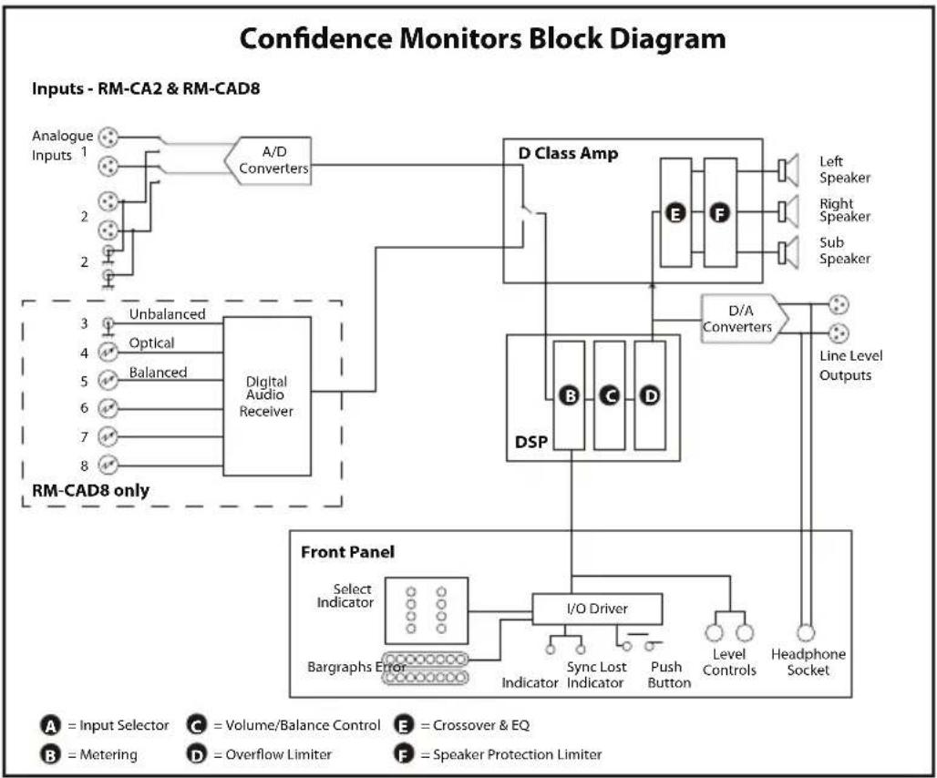
The three-way loudspeaker system is fed via a DSP-based active crossover and a trio of highly efficient Class-D amplifiers. Careful attention to driver selection, materials and case design, plus active DSP equalisation, has ensured a flat response and outstanding reproduction from such a shallow unit. A protective limiter prevents damage to the loudspeakers under overload conditions
The RM-CA2 operates from global mains voltages (85-264V AC, 47-63Hz) without adjustment.
natural_image
Abstract graphic with two white swords and a circular emblem on a blue grid background (no text or symbols)
natural_image
Abstract graphic with two stylized swords and a circular emblem on a blue grid background (no text or symbols)RM-CAD8 Confidence Monitor, 2 LED Meters, 2 Analogue & 6 Digital Stereo Inputs

Fig 1-2: RM-CAD8 Confidence Monitor Front Panel
The RM-CAD8 has all the features of the RM-CA2 together with the ability to select from an additional 6 stereo digital inputs. As well as the 2 stereo analogue inputs there are also:
• 1 x stereo S/PDIF unbalanced input on RCA phono female.
• 1 x stereo TOSlink unbalanced input on an optical connector.
- 4 x stereo AES/EBU balanced inputs on XLR 3 pin female.
The source select button illuminates to indicate loss of synchronisation lock to the incoming digital source.
A sample rate converter on the digital input allow sources of different sample rates to be connected and monitored, between 32kHz and 96kHz. All other features of the unit are identical to the RM-CA2.
System Block Diagram
flowchart
graph TD
    A["Analogue Inputs 1"] --> B["A/D Converters"]
    C["Unbalanced"] --> D["Digital Audio Receiver"]
    E["Optical"] --> D
    F["Balanced"] --> D
    G["3"] --> D
    H["4"] --> D
    I["5"] --> D
    J["6"] --> D
    K["7"] --> D
    L["8"] --> D
    M["RM-CAD8 only"] --> N["D Class Amp"]
    O["Front Panel"] --> P["DSP"]
    P --> Q["I/O Driver"]
    Q --> R["Select Indicator"]
    Q --> S["Bargraphs Error"]
    Q --> T["Indicator"]
    Q --> U["Sync Lost Indicator"]
    Q --> V["Push Button"]
    Q --> W["Level Controls"]
    Q --> X["Headphone Socket"]
    Y["Left Speaker"] --> Z["F"]
    AA["Right Speaker"] --> AB["F"]
    AC["Sub Speaker"] --> AD["F"]
    AE["Line Level Outputs"] --> AF["D/A Converters"]
    AG["A = Input Selector"] --> AH["C = Volume/Balance Control"] --> AI["E = Crossover & EQ"]
    AJ["B = Metering"] --> AK["D = Overflow Limiter"] --> AL["F = Speaker Protection Limiter"]
Fig 1-3: Confidence Monitor Block Diagram
Front Panel Indicators & Controls
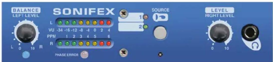
Fig 1-4: RM-CA2 Front Panel Controls
natural_image
Abstract graphic with two vertical bars and a circular emblem, set against a blue gradient background (no text or symbols)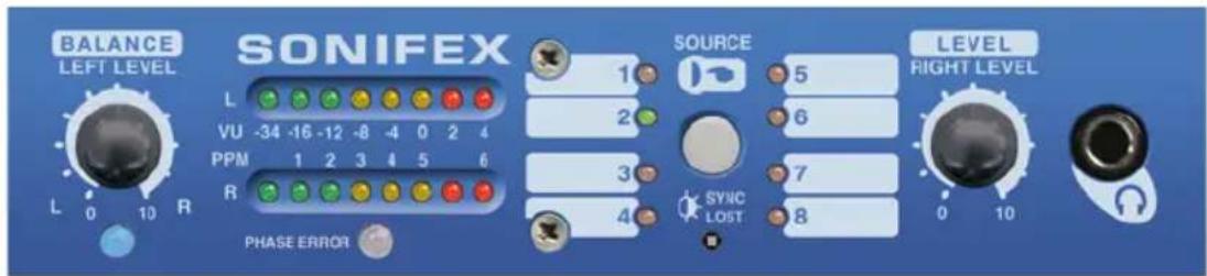
Fig 1-5: RM-CAD8 Front Panel Controls
Power LED
The POWER LED illuminates whilst internal power is present within the unit. If this indicator is not on, the most likely reason is simply the absence of mains power, but under fault conditions it may also indicate a ruptured mains fuse or a problem with the internal power supply module.
Source Selector
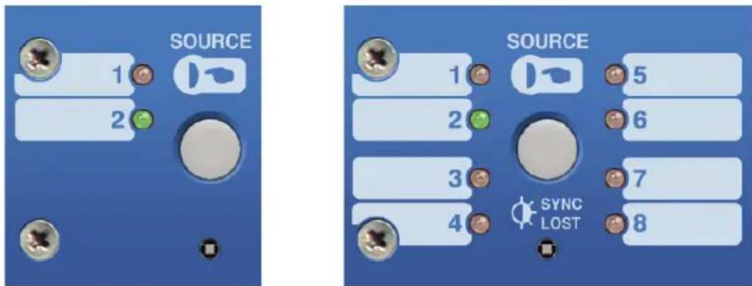
Fig 1-6: RM-CA2 Source Selector Button Fig 1-7: RM-CAD8 Source Selector Button
The Source Selector determines which of the two (RM-CA2) or eight (RM-CAD8) stereo audio inputs is routed to the loudspeakers and metering.
Pressing the Source selector button steps sequentially through all input sources. Once the last available source is selected, a further press returns the selection to the first source.
When mains power is removed, the currently selected Source is stored in non-volatile memory and recalled instantly once power is restored.
2
FRONT PANEL INDICATORS & CONTROLS
三
natural_image
Abstract graphic with two vertical bars and a circular emblem on a blue gradient background (no text or symbols)Sync Lost indicator
On the RM-CAD8 the Sync Lost indicator flashes when one of the following conditions is met. A digital audio input is selected and the digital audio signal is:
- missing,
- has a sample rate outside the acceptable range of the unit,
- contains invalid/non-audio data,
• or is too weak for the receiver to lock on to.
Main Meters
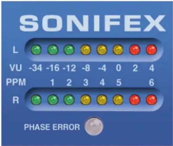
Fig 1-8: RM-CA2 & RM-CAD8 Meters & Phase Error LED
The main meters are twin 8-LED cluster, multicoloured bargraphs, displaying the currently selected stereo audio source. The upper meter displays the left channel and the lower meter the right channel.
Two different characteristics are available for the meters to suit different applications and regional preferences. The active meter characteristic is selected by the setting of DIPSwitch 7 on the rear of the unit.
PHASE Error LED
The Phase Error LED is triggered if the phase difference between the two channels of the currently selected input source remains consistently above 135 degrees.
Level and Balance Controls
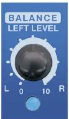
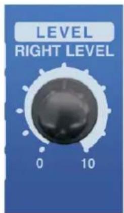
Fig 1-9: RM-CA2 Left Level or Fig 1-10: RM-CAD8 Right Level Balance Control and Power On Indicator or Stereo Level Control
There are two modes of operation for the level and balance controls determined by DIPSwitch 3. When the DIPSwitch is off, the level for each channel is independently controlled.
When the DIPSwitch is on, the level for both channels is set by the right hand potentiometer and the left hand potentiometer acts as a balance control to alter the stereo imaging by ±6dB .
The level potentiometers have a range of -52dB to +18dB gain. Also, moving the potentiometer fully anti-clockwise will mute the output. Position 6 on the level scale (1 o'clock) is a nominal unity gain position.
Headphone Output
The front panel headphone output is a 14 " (6.35mm) stereo jack socket capable of delivering over 80mW into 32Ω - 600Ω professional headphones at full volume. Higher impedance headphones may be used at reduced levels. Lower impedance headphones should not be used.
Inserting a plug into the headphone socket automatically mutes the internal loudspeakers.
natural_image
Abstract graphic with two white swords and a circular emblem on a blue gradient background (no text or symbols)3
REAR PANEL CONNECTIONS & OPERATIONS
[Non-Text]
![Sonifex RM-CA2 - [Non-Text] - 1](/content/2026/05/979205/images/29b26028a185db35559a602281f72ce8130da63e2405639b74153b7537796853.jpg)
natural_image
Abstract graphic with two stylized swords and a central circular emblem (no text or symbols)LIMIT indicators
![Sonifex RM-CA2 - [Non-Text] - 2](/content/2026/05/979205/images/be2f4e9d328cfe09c44d32f3e38c9ce3aab41834675c408d9818065e0baf5105.jpg)
bar
| Phase | Value | |-------|-------| | L | -34 | | VU | -16 | | PPM | 1 | | R | 2 |Fig 1-11: RM-CA2 & RM-CAD8 Meters & Phase Error LED
The LIMIT indicators are an additional function of the left hand LED (-34 VU) of the meter scales. When the level potentiometer gain is applied to the incoming signals the resulting signal can exceed the maximum input levels into the D-class amplifier. To avoid clipping or overflow conditions a limiter function is applied. The limiter is applied independently to each channel and has an instantaneous attack with a slow release.
While the limiter is active the left hand LED will flash. If the LED is continually flashing then the level potentiometer setting should be reduced so that the LED is always on or only flashes infrequently.
Note that for the limiter to be required the incoming signal level will need to exceed 0dB (VU -4). If the left hand LED is flashing but the meter levels are low then the incoming signal is lower than VU 34 and this does not indicate a limiter function.
Rear Panel Connections & Operation

Fig 1-12: Confidence Monitor RM-CA2 Rear

Fig 1-13: Confidence Monitor RM-CAD8 Rear
Audio Inputs
Three-pin female XLR connectors are provided for the connection of two analogue stereo audio sources and for the RM-CAD8 four digital stereo audio sources. The pin assignations
are as follows:
Pin 1: Ground
Pin 2: In-phase signal ("hot")
Pin 3: Out-of-phase signal ("cold")
Unbalanced signals may also be used by linking pins 1 and 3 and applying the unbalanced signal to pin 2.
Source two has a pair of RCA Phono connectors that are used to input an unbalanced analogue stereo signal input 2 sources are both connected to the input selector as a hard-wired mix. If you connect sources to the balanced and unbalanced inputs then both sources mixed together will be sent to the speakers, headphone and output when input 2 is selected.
For the RM-CAD8 there is also an S/PDIF unbalanced digital stereo audio input on a RCA phono connector and a TOSLink optical digital stereo audio input.
A full-scale digital input signal (0dBFS) corresponds to the maximum analogue input signal level of +18dBu (with no extra input gain applied).
All digital inputs are terminated 110Ω for XLR and 75Ω for phono.
Line Level Audio Outputs
A pair of three-pin male XLR connectors provides a stereo line-level analogue audio output carrying the selected audio Source signal. The XLR pin assignations are as follows:
Pin 1: Ground
Pin 2: In-phase signal ("hot")
Pin 3: Out-of-phase signal ("cold")
The signals may be unbalanced without loss of level by linking pins 1 and 3 and taking the unbalanced signal from pin 2.
Mains Power
Power is applied via a standard three-pin IEC male socket. Mains voltages between 85V and 264V AC and frequencies between 47 and 63Hz are accepted without adjustment. A 2A, 5 x 20mm SB fuse is used. The Earth pin MUST be connected to ensure safety.
Digital Input Termination
All electrical digital audio inputs are terminated. 110Ω for the balanced XLR inputs and 75Ω for the unbalanced S/PDIF inputs.

natural_image
Abstract graphic with two vertical bars and a circular emblem featuring stylized buildings (no text or symbols)3
REAR PANEL CONNECTIONS & OPERATIONS

natural_image
Abstract graphic with two vertical swords and a circular emblem (no text or symbols)DIPSwitch Settings
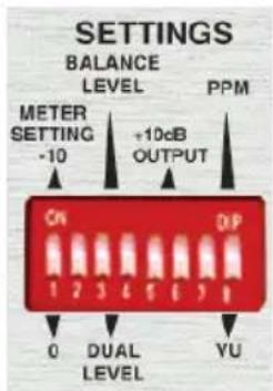
Fig 1-14: DIPSwitch Settings
Reduce Meter Levels by 10dB - DIPSwitch 1
This DIPSwitch is only valid when analogue input 2 is selected and when the switch is on it will reduce the meter levels by 10dB. This switch will mainly be used when the unbalanced inputs are used. In this case a 10dB gain is applied to the signal levels P650 that the inputs from domestic equipment will be increased to levels typically used for professional (unbalanced) equipment. If you wish to monitor the actual level of the unbalanced incoming signals then this switch needs to be on. On the other hand if the balanced input 2 is being used then the switch should be off.
Level/Balance Control Selection - DIPSwitch 3
This DIPSwitch switches the level and balance controls between independent left and right level (switch off) and stereo level and balance control (switch on).
Reduce Output Levels by 10dB - DIPSwitch 5
If the audio output is connected to unbalanced consumer equipment then this switch should be used to reduce the output levels by 10dB.
Meter Characteristic Selection - DIPSwitch 7
This DIPSwitch changes the metering characteristics between VU (off) and PPM (on).
DIPSwitches 2,4,6,8 are reserved for future use and should be left in the off position.
Technical Specification RM-CA2 & RM-CAD8
Inputs
Audio Inputs (RM-CA2): 2 x stereo analogue (1 x XLR balanced, 1 x XLR balanced or RCA phono unbal)
Audio Inputs (RM-CAD8): 2 x stereo analogue (1 x XLR balanced, 1 x XLR balanced or RCA phono unbal) 4 x stereo XLR balanced AES/EBU digital 1 x stereo RCA phono S/PDIF digital 1 x stereo optical TOSLink digital
Max Level (0dB Input Gain): +18dBu (analogue)/0dBFS (digital)
CMRR: >60dB typical
Analogue Input Impedances: XLR: >20kΩ balanced bridging RCA: >10kΩ unbalanced
Digital Input Impedances: (RM-CAD8 only): 110Ω ±20% AES/EBU balanced I/O 75Ω ±5% S/PDIF unbalanced I/O
AES/EBU Sample Rate: 32 to 96kHz, converted internally to 48kHz
Input Gain: +10dB on unbalanced analogue input
Selection: Front panel push button with indicator LEDs
Line Level Outputs
Audio Outputs: 1 x stereo analogue
Gain re Selected Input: Unity or -10dB (switchable) & level control from front panel
Maximum Output Level: +18dB
Output Impedance: <50 ohms
Distortion: <0.02% (1kHz, +8dBu output)
Noise: -95dB RMS, unity gain ref +8dBu output
Frequency Response: 20Hz-20kHz +0/-0.5dB
Crosstalk Analogue I/O, ref 0dBu 1kHz input: <-90dB 10kHz input: <-85dB

natural_image
Abstract graphic with two white swords and a circular emblem on a blue grid background (no text or symbols)4
TECHNICAL SPECIFICATION RM-CA2 & RM-CAD8
natural_image
Abstract graphic with two vertical bars and a circular emblem, set against a blue gradient background (no text or symbols)Amplifier/Loudspeakers
Configuration: Three-way with stereo mid/high-frequency drivers & monolow-frequency driver
Power Output: 2 x 7W (HF) + 15W (LF) with protective limiter
Crossover: 250Hz (24dB/octave, Linkwitz-Riley)
Distortion (HF Outputs): < 0.1% (1kHz, 3W output)
Distortion (LF Output): < 0.1% (100Hz, 6W output)
Noise: More than 102dB below full output
Volume: Mute to full volume via front panel rotary control (mute, -52 to +18dB)
Balance Trim: ±6dB via front panel rotary control.
Peak Acoustic Level: 96dB SPL @ 2ft
Level & Phase Metering
Number: 2 x 8-segment LED bargraphs
Line-Up Level: 0dB on scale can be set to 0dB or -10dB for analogue input 2 via rear panel DIP switch
Phase Meter: Single LED indication showing error
Connectors
Audio Inputs 4 x XLR 3-pin female balanced (RM-CA2): 2 x RCA female phono unbalanced
Audio Inputs 4 x XLR 3-pin female analogue (RM-CAD8): 2 x RCA phono analogue
4 x XLR 3-pin female AES/EBU digital
1 x RCA phono female S/PDIF digital
1 x optical TOSLink digital
Audio Outputs: 2 x XLR 3-pin male (balanced, may be unbalanced)
Headphones: 1/4" (6.35mm) A-gauge 3-pole stereo jack socket
Mains Input: Filtered 3-pin IEC male, continuously rated 85 - 264VAC, 47 - 63Hz, fused, 60W peak, 30W average
Fuse Rating: Anti-surge fuse 2A 20 x 5mm
Equipment Type
RM-CA2: Confidence Monitor, 2 LED meters, 2 analogue stereo inputs
RM-CAD8: Confidence Monitor, 2 LED meters, 2 analogue & 6 digital stereo inputs
Physical Specification
Dimensions 48cm (W) x 27cm (D) x 4.4cm (H) (1U) (Raw): 19" (W) x 12" (D) x 1.73" (H) (1U)
Dimensions 55cm (W) x 43cm (D) x18cm (H) (Boxed): 21.7" (W) x 16.9" (D) x 7.1" (H)
Weight:
Nett: 4.4kg
Gross: 5.8kg
Nett: 10lb
Gross: 13lb
natural_image
Abstract graphic with two vertical bars and a circular emblem on a blue textured background (no text or symbols)SONIFEX
www.sonifex.co.uk
t:+44 (0)1933 650 700
f:+44 (0)1933 650 726
sales@sonifex.co.uk

- Confidence Monitors User Handbook
- Warranty i
- Safety Information iv
- Installation Information v
- Confidence Monitors Introduction 1
- RM-CA2 Confidence Monitor, 2 LED Meters & 2 Analogue Stereo Inputs 3
- RM-CAD8 Confidence Monitor, 2 LED Meters, 2 Analogue & 6 Digital Stereo Inputs 4
- Technical Specification RM-CA2 & RM-CAD8 11
- Figures
- Warranty
- Warranty and Liability
- Unpacking the Confidence Monitor
- Item Quantity Confidence Monitor
- Returning the Warranty Card
- Safety Information
- Safety of Mains Operated Equipment
- Voltage Setting Checks
- Fuse Rating
- Power Cable and Connection
- Wire Colour Connection
- Ordering the Correct Mains Lead
- Installation Information
- Atmosphere
- Electromagnetic Radiation
- WEEE & ROHS DIRECTIVE
- WEEE & RoHS Directives - Sonifex Statement
- Confidence Monitors Introduction
- Detail In The Design
- Anti-Vibration
- Accurate Sound System
- 1
- 三
- DSP Based Design
- Features Summary
- RM-CA2 Confidence Monitor, 2 LED Meters & 2 Analogue Stereo Inputs
- RM-CAD8 Confidence Monitor, 2 LED Meters, 2 Analogue & 6 Digital Stereo Inputs
- System Block Diagram
- Power LED
- 2
- FRONT PANEL INDICATORS & CONTROLS
- Sync Lost indicator
- Main Meters
- PHASE Error LED
- Level and Balance Controls
- Headphone Output
- 3
- REAR PANEL CONNECTIONS & OPERATIONS
- [Non-Text]
- Audio Inputs
- Line Level Audio Outputs
- Mains Power
- Digital Input Termination
- DIPSwitch Settings
- Reduce Meter Levels by 10dB - DIPSwitch 1
- Level/Balance Control Selection - DIPSwitch 3
- Reduce Output Levels by 10dB - DIPSwitch 5
- Meter Characteristic Selection - DIPSwitch 7
- Technical Specification RM-CA2 & RM-CAD8
- Inputs
- Line Level Outputs
- 4
- Amplifier/Loudspeakers
- Level & Phase Metering
- Connectors
- Equipment Type
- Physical Specification
- SONIFEX
Brand : Sonifex
Model : RM-CA2
Category : Loudspeaker