
Listen Up - Keyboard 4ms - Free user manual and instructions
Find the device manual for free Listen Up 4ms in PDF.


| Product Type | Full-size keyboard |
| Dimensions (W x D x H) | 440 x 130 x 30 mm |
| Weight | 500 g |
| Power Supply | USB (5V, 100mA) via detachable cable |
| Number of Keys | 104 (US layout) with hotkeys |
| Key Switch Type | Membrane rubber dome |
| Connectivity | USB Type-C to USB-A cable (1.5 m) |
| Compatible Operating Systems | Windows, macOS, Linux |
| Multi-Key Rollover | 24-key anti-ghosting |
| Special Functions | Audio volume control, media keys, sleep mode button |
| LED Backlight | Single-color white backlight with adjustable brightness |
| Cable Length | 1.5 m |
| Material | ABS plastic case, PBT keycaps |
| Operating Temperature | 0°C to 40°C |
| Storage Temperature | -20°C to 60°C |
| Humidity | 20% to 80% non-condensing |
| Maintenance & Cleaning | Unplug before cleaning; use soft dry cloth. Avoid liquids. |
| Safety Precautions | Keep away from moisture, do not disassemble. Use only with USB ports. |
| Spare Parts & Repairability | No user-serviceable parts; contact support for repairs. |
| Warranty | 1 year limited hardware warranty |
Frequently Asked Questions - Listen Up 4ms
User questions about Listen Up 4ms
0 question about this device. Answer the ones you know or ask your own.
Ask a new question about this device
Download the instructions for your Keyboard in PDF format for free! Find your manual Listen Up - 4ms and take your electronic device back in hand. On this page are published all the documents necessary for the use of your device. Listen Up by 4ms.
USER MANUAL Listen Up 4ms
(Expander for Listen Four and Listen IO)
4ms Company
User Manual 1.0 - Sept. 19, 2019


natural_image
Close-up of a green printed circuit board with black connectors and labeled components (no readable text or symbols beyond labels)The Listen Up is a passive expander module which provides stereo 1/4" (6.35mm) jacks for the Listen IO, Listen Four, and WAV Recorder modules. There are two pairs of stereo jacks, each pair connects to a module using the included 3-pin cables. Both pairs of jacks can be connected to the same module to provide 1/4" (6.35mm) inputs or outputs, or each of the two pairs can be connected to separate modules. The module requires no power and is available as a kit or built unit. For convenience, the top pair of jacks is labeled "Left/Right In" and the bottom pair is labeled "Left/Right Out", but either pair of jacks can be used as an input or output.
The Listen Up features:
- Four 1/4" (6.35mm) jacks arranged in two stereo pairs.
• Each stereo pair can be connected to the same module or to separate modules.
• Each stereo pair (left/right) is bi-directional (input or output). - Left In and Left Out jacks are TRS stereo if corresponding Right jack is not unpatched.
- Uses no power.
- Connects directly to host module using 3-pin cables.
- Two 3-pin cables included.
·4HP
Setting up your Listen Up
natural_image
Close-up of an electronic circuit board with visible traces and components (no readable text or symbols)- Power off your Eurorack system.
- Plug one of the included 3-pin cables to one of the 3-pin connectors on the back of the Listen Up.
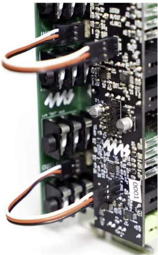
- Plug the other end of the cable to a 3-pin connector on the back of the main module (Listen IO, Listen Four, or WAV Recorder). Make sure the same color wire is facing towards the top at both ends of the cable.
- If you want to connect the Listen Up to another 3-pin header (on the same or different module), use the other included 3-pin cable and repeat the previous two steps.
- Using the included screws, securely attach the Listen Up to the rails of your case.
- Power on your Eurorack system.
FAQ
Which way do I connect the 3-pin cable?
It does not matter which color wire is on top, just be consistent. In the example images, the white wire is on top. If you reverse one side of the cable (e.g. white wire on top at one end, and black wire on top at the other end) then the modules will function perfectly, except that the left and right channels will be swapped.
My Listen IO or Listen Four module has two (or more) headers, which one do I use?
On the Listen IO and Listen Four, there are headers labeled INS and OUTS. You can choose either one (or both), depending on whether you want to use the Listen Up for 1/4" inputs or outputs (or both).
Can I use the Left In and Right In jacks as outputs?
Yes! And you can use the Left Out and Right Out jacks as inputs. Both sets of jacks are bi-directional and identical. The faceplate is labeled for a common typical use (stereo inputs and stereo outputs) but you can safely use either pair of jacks for any signal.
Why are the Left In/Out jacks labeled "stereo"?
If you want to use a TRS stereo cable with the Listen Up, plug it into the left jack and do not plug anything into the right jack. The right signal will appear on the ring of the TRS cable, and the left signal will appear on the tip.
If you want to connect a stereo signal using two cables (one for left and one for right), then plug the cables into the left and right jacks of the Listen Up. The jacks are compatible with TS (mono) and TRS (stereo) cables, but the TRS stereo feature will only be active if the right jack is not patched.


natural_image
Close-up of a circuit board with electronic components and wiring, no readable text or symbols present.Look at the back of your Listen IO module to see what version you have. Version 1.0 and 1.0RC1 are the same. Version 1.1 and 1.2 are described in the following section.
The Listen IO version 1.0 has two headers: INS and OUTS. Both headers correspond to the 1/8" (3.5mm) line level jacks. Connecting a Listen Up allows you to add 1/4" (6.35mm) line-level inputs and outputs to your modular system. Typically, you will connect the top header of the Listen Up to the top header of the Listen IO, and the bottom header of the Listen Up to the bottom header of the Listen IO (see photo above on the right). Alternatively, you can choose to connect only one of the headers and use the second Listen Up header for a different module.
Connecting a Listen IO to the INS header will connect the 1/4" (6.35mm) jacks to the Line In on the top half of the Listen IO.
Connecting a Listen IO to the OUTS header will connect the 1/4" (6.35mm) jacks to the Line Out of the bottom half of the Listen IO.
You can always use the Listen IO's jacks at the same time as the Listen Up's 1/4" (6.35mm) jacks. The signals will be automatically mixed and/or split.

The Listen IO version 1.1 and later versions have four headers: LINE IN and MOD OUT on the top; MOD IN and LINE OUT on the bottom. You can use two of these pairs with a single Listen Up module. (If you have two Listen Up's then you can use all four headers).
The LINE IN header connects to the Line In section on the top half of the Listen IO. Connecting a Listen Up here will give you 1/4" (6.35mm) line level inputs. The signal will be boosted by the Listen IO to modular level and will output on the Listen IO's Mod Out 1/8" (3.5mm) jacks.
The MOD OUT header connects to the Mod Out section on the top half of the Listen IO. Connecting a Listen Up here will give you 1/4" (6.35mm) modular level outputs. This can be useful for connecting to modular synthesizers with 1/4" jacks that input +/-12V or +/-15V signals.
The MOD IN header connects to the Mod In section on the bottom half of the Listen IO. Connecting a Listen Up here will give you 1/4" (6.35mm) modular level inputs. This can be useful for connecting from modular synthesizers with 1/4" jacks that output +/-12V or +/-15V signals. The signal will be attenuated by the Listen IO module (based on the position of the bottom knob) and will output on the Listen IO's Line Out jacks.
The LINE OUT header connects to the Line Out section on the bottom half of the Listen IO. Connecting a Listen Up here will give you 1/4" (6.35mm) line level outputs.
In all cases, you can use the jacks on the Listen Up at the same time as the jacks on the Listen IO. The signals will be automatically mixed and/or split without attenuation.


natural_image
Close-up of a black electronic circuit board with various components and wiring, no readable text or symbols present.The Listen Four has two headers: INS and OUTS.
Connecting the Listen Up to the INS header will provide 1/4" (6.35mm) inputs to the Listen Four as a fifth channel. The other four channels on the Listen Four can be used as normal. There will be no level control for the signal coming from the Listen Up, except for the Main Level knob and the headphone level knob.
Connecting the Listen Up to the OUTS header will provide 1/4" (6.35mm) main outputs to the Listen Four. The Listen Four's Main Level knob will control the volume of the outputs. Note that even though the Left Out jack on the Listen Up works with TRS cables to carry a stereo signal, it will not output a balanced signal. To use balanced 1/4" (6.35mm) stereo signals, we recommend the Listen Four Quarters module.

The WAV Recorder has one 3-pin header which connects to the input jacks on the WAV Recorder. The normalization jumper on the WAV Recorder must be removed (see WAV Recorder User Manual). Connecting a Listen Up to a WAV Recorder will allow you to record directly from 1/4" (6.35mm) cables. Note that if you are using line level signals on the 1/4" cables, you should set the Gain knob of the WAV Recorder to maximum.
Electrical and Mechanical Specifications
• 4HP Eurorack format module.
- 0.94" (23.8mm) maximum depth.
• Passive module, requires no power.

- (Expander for Listen Four and Listen IO)
- 4ms Company
- The Listen Up features:
- Setting up your Listen Up
- FAQ
- Which way do I connect the 3-pin cable?
- My Listen IO or Listen Four module has two (or more) headers, which one do I use?
- Can I use the Left In and Right In jacks as outputs?
- Why are the Left In/Out jacks labeled "stereo"?
- Electrical and Mechanical Specifications
Brand : 4ms
Model : Listen Up
Category : Keyboard