
PS-A43SPB - Griddle Fusion - Free user manual and instructions
Find the device manual for free PS-A43SPB Fusion in PDF.


| Product Type | Griddle |
| Brand | Fusion |
| Model | PS-A43SPB |
| Dimensions | 60 x 40 x 10 cm (approx.) |
| Weight | 10 kg (approx.) |
| Power Supply | Electric, 220-240 V, 2000 W |
| Cooking Surface Material | Stainless steel |
| Non-stick Coating | Yes, PTFE-free |
| Temperature Control | Adjustable thermostat with indicator light |
| Heating Zones | 3 independent zones |
| Drip Tray | Removable, dishwasher safe |
| Legs | 4 adjustable, non-slip |
| Safety Features | Overheat protection, cool-touch handles |
| Cleaning | Wipe with damp cloth; drip tray dishwasher safe |
| Spare Parts Available | Yes (drip tray, knobs, heating element) |
| Warranty | 2 years |
| Certifications | CE, RoHS |
Frequently Asked Questions - PS-A43SPB Fusion
User questions about PS-A43SPB Fusion
0 question about this device. Answer the ones you know or ask your own.
Ask a new question about this device
Download the instructions for your Griddle in PDF format for free! Find your manual PS-A43SPB - Fusion and take your electronic device back in hand. On this page are published all the documents necessary for the use of your device. PS-A43SPB by Fusion.
USER MANUAL PS-A43SPB Fusion
Garmin 1 , the Garmin logo, FUSION 2 , and the Fusion logo are trademarks of Garmin Ltd. or its subsidiaries, registered in the USA and other countries. These trademarks may not be used without the express permission of Garmin.
Failure to follow these warnings and cautions could result in personal injury, damage to the vehicle or vessel, or poor product performance.
This device must be installed according to these instructions.
Disconnect the vehicle's or vessel's power supply before beginning to install this product.
CAUTION
Continuous exposure to sound pressure levels over 100 dBA may cause permanent hearing loss. The volume is typically too loud if you cannot hear people speaking around you. Limit the amount of time you listen at high volume. If you experience ringing in your ears or muffled speech, stop listening and have your hearing checked.
Always wear safety goggles, ear protection, and a dust mask when drilling, cutting, or sanding.
NOTICE
When drilling or cutting, always check what is on the opposite side of the surface.
It is strongly recommended that you have your audio system installed by a professional installer to ensure optimum performance.
You must read all installation instructions before beginning the installation. If you experience difficulty during the installation, go to www.fusionentertainment.com for product support.
What's In the Box
- Mounting spacer
• Eight 6-gauge, self-tapping stainless steel screws
• Six M4, self-tapping black screws
Tools Needed
Electric drill
• Drill bit (size varies based on surface material)
- Screwdriver
• Appropriate saw or utility knife to cut surface material
• Marine sealant (optional)
NOTE: If you use the mounting spacer, you must use the six black screws supplied with the mounting spacer to mount the stereo to the mounting spacer. Do not use the six stainless steel screws supplied with the FUSION® Panel-Stereo.
NOTE: For customized installations, additional tools and materials may be needed.
FUSION Panel-Stereo Spacer Orientation
You can use the spacer cutout to run the stereo cables over the top of the installation surface or through a hole in the installation surface.
If you route the cables through a hole in the installation surface, you can rotate the spacer 180 degrees to hide the spacer cutout from below.
Installing the Spacer
1 Select the mounting surface, and prepare the mounting surface as directed in the FUSION Panel-Stereo Installation Instructions.
2 Hold or secure the spacer temporarily to the selected mounting location.
3 Using the eight mounting slots on the spacer, mark the locations of the holes.
4 Remove the spacer.
5 Using an appropriate drill bit for the mounting surface and screw type, drill the holes.
6 Place the spacer ① over the installation location ②.

NOTICE
Do not apply grease or lubricant to the screws when fastening the spacer to the mounting surface and the stereo to the spacer. Grease or other lubricants can damage the spacer and the stereo housing.
7 Secure the spacer to the surface using the silver screws ③ included with the spacer or screws appropriate for the depth of the mounting surface.
8 Make the necessary wiring connections as directed in the FUSION Panel-Stereo Installation Instructions.
NOTE: If you run the cables along the wall, route the cables through the cutout. To route the fuse holder through the cutout, open the lid of the fuse holder. Close the lid when the fuse holder is in position.
NOTE: If you route the cables through a hole in the installation surface, use a rubber grommet to protect the stereo wires from sharp edges.
9 Place the stereo ④ on the spacer, and secure it to the spacer using the black screws ⑤ included with the spacer.
10 Press the trim ⑥ firmly onto the stereo, until all of the pins snap into place.
Dimension Drawings
Front View
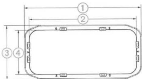
| Dimension | Measurement |
| 1 | 349 mm (13.74 in.) |
| 2 | 319.5 mm (12.58 in.) |
| 3 | 160.5 mm (6.32 in.) |
| 4 | 131 mm (5.16 in.) |
Side View

| Dimension | Measurement |
| 1 | 43 mm (1.68 in.) |
| 2 | 160.5 mm (6.32 in.) |
Specifications
| Dimensions (W x H x D) | 349 x 160.5 x 43 mm (13.74 x 6.32 x 1.69 in.) |
| Weight | 257 g (9.1 oz.) |
Brand : Fusion
Model : PS-A43SPB
Category : Griddle