
HY55200-3 - Compressor HYUNDAI - Free user manual and instructions
Find the device manual for free HY55200-3 HYUNDAI in PDF.


| Product Type | Air Compressor |
| Brand | Hyundai |
| Model | HY55200-3 |
| Power Supply | 230 V / 50 Hz |
| Motor Power | 1.5 HP (1100 W) |
| Tank Capacity | 50 liters |
| Max Pressure | 8 bar (116 psi) |
| Air Flow Rate | 220 L/min |
| Number of Cylinders | 1 |
| Dimensions (L x W x H) | 60 x 30 x 50 cm |
| Weight | 18 kg |
| Noise Level | 97 dB(A) |
| Safety Valve | Yes, at max pressure |
| Thermal Overload Protection | Yes, automatic reset |
| Oil Type | SAE 30 or equivalent |
| Oil Capacity | 0.3 L |
| Maintenance Interval | Check oil every 50 hours, change every 500 hours |
| Air Filter | Washable foam, clean every month |
| Drain Valve | Bottom mounted, manual |
| Included Accessories | Air hose (5 m), tire chuck, blow gun, inflation needle |
| Warranty | 2 years |
| Repairability Index | 7.5 / 10 (spare parts available) |
Frequently Asked Questions - HY55200-3 HYUNDAI
User questions about HY55200-3 HYUNDAI
0 question about this device. Answer the ones you know or ask your own.
Ask a new question about this device
Download the instructions for your Compressor in PDF format for free! Find your manual HY55200-3 - HYUNDAI and take your electronic device back in hand. On this page are published all the documents necessary for the use of your device. HY55200-3 by HYUNDAI.
USER MANUAL HY55200-3 HYUNDAI
3 PHASE ELECTRIC AIR COMPRESSOR HY55200-3 & HY75270-3
User Manual
CONTENTS
- PARTS 3.
- INTRODUCTION 4.
- ELECTRICAL NOTES 5.
- INSTALLATION 5/6.
- START UP 6/7.
- MAINTENANCE 7/8/9.
- PRESSURE SWITCH ADJUSTMENTS 9/10.
- ELECTRICAL CONNECTIONS 10/11.
- SPECIFICATIONS 12.
- DECLARATIONS of CONFORMITY 12.
- RECYCLING 13.
-
WARRANTY 13.
-
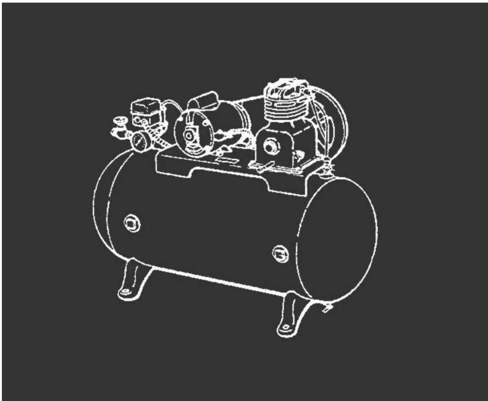
PARTS.

- Base
- Tank drain
- Pressure relief valve
- Belt guard
- Compressor
- Air filter
- Drive belt
- Electric motor
- Pressure-gauge
- Air tank
- Air outlet valve
2. INTRODUCTION.
Read this manual carefully before installing, using or carrying out any maintenance on your compressor.
This instrucon manual has been written to simplify installaon, maintenance and general use of your new compressor. Strict observance to the content of this manual is essential to ensure a correct and economical operation of the compressor.
The “Warning” notes, underline those operaons which, if not carried out correctly could cause damage to the equipment and injury to the user.
We strongly recommend only genuine Hyundai replacement spare parts are used, which will guarantee the eciency and service life of the compressor.
N.B. Warning
Use of non-genuine parts invalidates our warranty on your compressor.
INSTALLATION.
Having removed the compressor from it's packaging and check that it is in perfect condition; you are now ready to install your new compressor as follows:
2.1 Portable compressors.
Fit the wheels and rubber foot as required (Fig 1).
Connue as staonary.
2.2 2 Staonary compressors.
2.2a Site the compressor on a level surface in a clean dry area (Fig 4). It is essenal the compressor should has a 1 metre clearance from the surrounding walls and 2 metres from the ceiling to ensure proper venlaon and ecient cooling. If the compressor is sited in a small room there must be a minimum of two air changes per min to provide adequate ventilaon. To achieve this it may require the use of both an input and extract fans to ensure the room temperature does not exceed 40° C.
2.2b It is further recommended that compressors used for painng be located in a separate room, away from the area where sanding/grinding and painng is done. Abrasive parcles or paint found to have clogged the air intake liter and valves shall automatically void warranty.
N.B. Minimum Working temperature +5°C
2.2c Compressors that are receiver mounted or skid-base packages should not be bolted to the oor but installed on an-vibraon mounts. When using an-vibraon mounts it is essenal to use a exible pipe to connect the compressor to the installed system.
2.2d Air leaks if not corrected will cause excess wear in the compressor and can result in the compressor not being able to provide the air required.
3. ELECTRICAL NOTES.
3.3 Always use a qualified electrician to connect the compressor to the mains. Check electrical supplies match compressor specification as per the motor informaon plate (g 6).
3.4 All compressors are supplied with a power cable of 2 metres for conneccon to a fused isolator close to the compressor. (not supplied) sited close to the compressor.
3.5 Single phase compressors can be ed with an appropriate plug (Fig 5) & (Table
1). It is extremely important that aenon is paid to the technical data sheet to establish the correct fuse and plug are used for the parcular compressor in queson.
N.B. Warning
Failure to use the correct plug and fuse could cause damage to the equipment and injury to the user, and will invalidate the warranty.
Three phase 2hp to 7.5hp compressors are ed with a direct on line starter/pressure switch complete with 2 metres of cable for conneccon to a fused isolator (not supplied).
A 10hp three phase compressor is supplied with a star-delta starter, which is pre-wired with 2 metres of cable. The starter should be connected to a fused isolator (not supplied).
| TABLE 1 | HP | Supply voltage | Fuse / Plug type |
| 2-3* | 230/1/50 | 13 amp at 3 pin - EEC282 | |
| 3-4 | 230/1/50 | 32 amp 3 pin - EEC282 | |
| 2-3-3.5-4 | 400/3/50 | 16 amp 4 pin - EEC282 | |
| 5.5-7.5-10 | 400/3/50 | 32 amp 4 pin - |
* Only compressors ed with so start and low current motors can be used with 13 amp plugs.
TANDEM/DUPLEX COMPRESSORS
- Installaon for these compressors requires a qualified electrician to connect the compressor to the mains.
- Both tandem and duplex compressors (two pumps on same receiver) are supplied with a med starter to make sure that there is a me lapse between each compressor starng.
4. INSTALLATION.
Secure starter panel (when supplied) to the wall or a xed support and connect to a fused isolator adjacent to the control panel, or connect power cable direct to fused isolator (not supplied). Cable to the isolator should be suitable for the total HP/Kw been used (see Table 2). If an extension to the supply is required, it should have a cross secon for the wires in proporon to its length, (see Table 2).
VALID SECTION FOR A MAXIMUM LENGTH OF 20 METRES
| TABLE 2 | HP/kw | 220/230 Volt | 380/400 Volt |
| 2-3-3.5/1.5-2.2-2.6 | 2.5 sq mm | 1.5 sq mm | |
| 5.5/4 | 2.5 sq mm | ||
| 7.5/5.6 | 2.5 sq mm | ||
| 10/7.5 | 4.0 sq mm | ||
| 20/15 | 10 sq mm |
N.B. Warning any extension of supply cable should not be less in secon than the cable tted to the compressor by the factory.
CAUTION
Never use the ground clamp in place of the neutral clamp to provide a single phase supply.
Earthing connecons must be carried out in accordance with the safety regulaons (EN60204).
The power cable plug or socket/isolator must not be used to stop the compressor, as this could cause damage to the compressor when restarng. Always stop compressor via the pressure switch (Fig 7) on/o buon.
Always use a suitably fused isolator sited close to the compressor. The isolator should preferably be ed with a trip to avoid damage to the motor due to the loss of a phase.
The compressor pump and delivery pipe can reach very high temperatures. Use extreme cauon when working in the proximity of these parts. To avoid burns, do not touch these parts (Fig 11).
5. START UP.
5.1 Compressors with DOL & Star/delta starters (Single/Three Phase).
5.1a Check that the line voltage corresponds to the motor data plate (Fig 6), tolerance must not exceed + or - 5%.
5.1b Turn switch on pressure switch to posion "O" (OFF) (Fig 7). Connect to mains and switch power on.
5.1c Turn switch on pressure switch to posion "1" (ON) (Fig 7). Compressor will now start. The pressure switch will automatically control the stopping and starng of the compressor to the factory standard sengs.
5.1d Check the rotaon of the compressor as this is of parcular importance to ensure the correct cooling and lubrication of the compressor. See arrow on motor and y wheel. (Fig 12).
N.B. Warning Because an automac pressure switch controls the compressor, the compressor will start without warning.
5.2 Compressors with tandem and duplex starters.
5.2a Turn switch on pressure switch to posion "O" (OFF) (Fig 7).
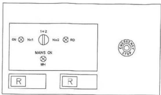
5.2b Select the duty cycle by turning the control knob to the required seng (Fig 9).
5.2c Turn switch on pressure switch to posion "1" (ON) (Fig 7). Compressor will now start and be controlled in accordance with the duty selected. The pressure switch will automatically control the stopping and starng of the compressor to the factory standard sengs.
| Posion 1 | Only number one compressor runs |
| Posion 3 | Only number two compressor runs |
| Posion 2 | Both compressors run |
N.B. Warning Because an automac pressure switch controls the compressor, the compressor will start without warning.
5.3 Overload protecon.
5.3a The single phase electric motors are equipped with an amperometric thermal cut-out with manual reset located on the terminal box at the top of the electric motor.
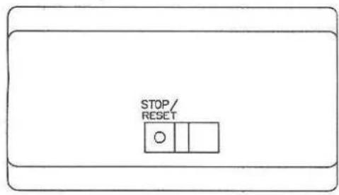
When the thermal cut-out intervenes, wait several minutes, then manually reset the thermal switch (Fig 12).
- With three phase compressors, the cut-out is automac and is located inside the pressure switch. When the thermal cut-out intervenes, the pressure switch cuts-out and moves to the posion “O” (OFF)(Fig 7), wait 10 minutes and turn the pressure switch back to posion “1” (ON) (Fig 7).
- With compressors equipped with a wall mounted starter the thermal cut-out is located on the inside of the starter unit. When the thermal cut-out intervenes, turn the pressure switch to posion “O” (OFF) (Fig 7), wait several minutes, then manually reset the thermal overloads.
- To Reset thermal overloads push the blue reset buons on the front cover of the wall mounted starter unit.
- Restart the compressor by the steps described in the secon "Start Up"
6. MAINTENANCE.
CAUTION Before performing any maintenance on the compressor make sure that:
The compressor is isolated from the electrical supply. The pressure switch and switches on the power unit are turned to posion "OFF".
The receiver is drained of any compressed air.
6.1 Cleaning and changing lter cartridge.
Clean the air intake Iters every month by blowing compressed air from the inside of the Iter to the outside of the Iter or cartridge (Fig. 14).
We recommend replacing the Iter cartridge or Iter element at least twice a year if the compressor operates in a clean environment and more frequently if the compressor is located in a dusty environment.
6.2 General maintenance.
Check the tension of the belts every month and adjust them if necessary.
Release the condensate from the air receiver at least once a day by opening the discharge tap (Fig. 15).
Thoroughly clean all external parts of the compressor and motor every 6 months or 2000 running hours to ensure proper cooling.
6.3 Oil.
Check oil level every day (Fig. 3) when compressor is cold, top up as necessary. Use Hyundai 100 OIL or SAE10W/30 engine oil.
6.4 Oil change.
Remove the drain plug (Fig 16) to drain the oil and then re-t drain plug. Top up to the appropriate oil level as (Fig 3). FIAC 100 oil should be changed every 6 months or 2000 running hours which ever is reached rst. Alternatively you can use or SAE10W/30 engine oil, Oils other than FIAC 100 should be replaced every 3 months or 250 hours.
6.5 Emergency STOP buon (TANDEM ONLY).
The emergency stop buon (Fig17) is located on the wall-mounted starter this allows the compressor to be stopped in an emergency. DO NOT USE THIS SWITCH AS A POWER SWITCH. To reset the emergency buon, rotate the red knob an-clockwise a half turn. To restart the compressor refer to "START UP" (Page 4) relevant to your compressor.
6.6 How to x minor faults.
6.6a Air leak from pressure switch valve. These are caused by air leaking from the receiver through the non-return valve.
6.7 How to x it. (Fig. 18).
6.7a Empty the tank of compressed air completely.
6.7b Unscrew the hexagonal head of the valve (Fig. 18) (A).
6.7c Clean or replace the rubber disk (Fig. 18) (B) and clean the housing thoroughly.
6.7d Re-assemble the unit carefully.
6.8 The compressor runs but does not produce air.
6.8a Check the inlet and outlet valves (Fig. 19) and gasket for damage.
6.8b Replace damaged parts using Service Kit No.1.
WARNING
Never unscrew any joints with the air receiver under pressure, always ensure that the air receiver is empty of compressed air.
Do not work on the compressor without disconnecting the unit from the electrical power supply.
Ambient working temperature range +5°C to +40°C
Do not direct water or inammable liquids towards the compressor.
Do not place inammable objects near the compressor. Do not place any arcs on or near the compressor, this will impede the cooling and could cause a re.
When the compressor is not being used turn the pressure switch to the "OFF" posion. (Fig. 7).
Never direct compressed air at persons or animals.
Do not transport the compressor with the tank under pressure.
Keep children and animals away from the area where the machine is operang.
Aer using the compressor always disconnect from the electrical supply.
6.9 If the compressor is used for painng.
6.9a Do not operate the compressor in closed spaces or in the proximity of naked ames and spray vapour.
6.9b Make sure that the room where you are working has a Sucient change of air (Min 2 per minute, see installaon notes). (Fig. 20).
6.9c Use an appropriate mask to protect nose and mouth (Fig. 20).
Compressed air receivers for the European market are built in accordance with EC Direcve 09/105.
Air Compressors for the European market are built in conformity with the Directive 2006/42/EC
7. PRESSURE SWITCHADJUSTMENTS.
NE-MA Single Phase
N.B. Warning
Switch o power at fused isolator before making any adjustment to the pressure-switch.
7.1 NE-MA pressure switch is supplied with a standard cut out pressure 150 psi and a cut in pressure of 120 psi.
7.2 The cut out seng can be adjusted to suit your individual requirement as follows:
7.1a Increase or decrease cut out pressure. Adjust (A) clock wise to increase, an-clock wise to decrease (Fig 21).
N.B. Warning Pressure must not exceed maximum working pressure of the receiver.
NE-MA Fig 21

MDR-3 Three Phase
N.B. Warning Switch o power at fused isolator before making any adjustment to the pressure-switch.
7.3 MDR-3 pressure switch is supplied with a standard cut out pressure 150 psi and a cut in pressure of 120 psi.
7.4 Both these sengs can be adjusted to suit your individual requirement as follows:
7.4a Increase or decrease cut out pressure. Adjust the central upper pressure screw (A) clockwise to increase or an-clockwise to decrease (Fig 23.
7.4b Increase or decrease dierenal pressure. With a screwdriver adjust the pressure dierenal screw (B) clockwise to increase, an-clock wise to decrease (Fig 23).
Note: From me to me the pressure switch sengs may vary and should be adjusted as per above (This is NOT covered by warranty).
MDR 3 Fig 22
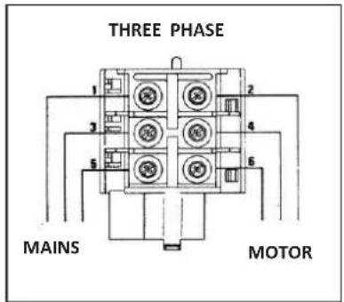
MDR 3 Fig 23
ATTENTION
Adjustments are to be carried out only when the switch mounted, under pressure and voltage free.

8. ELECTRICAL CONNECTIONS.
ELECTRIC MOTOR TERMINAL BOARD CONNECTION
230/50/1 MOTORS

400/50/3 MOTORS STAR DELTA
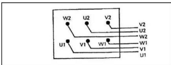
400/50/3 MOTORS D.O.L.
![graph TD A["U1"] --> B["W2"] C["V1"] --> D["V2"] E["W1"] --> F["V2"]](/content/2026/05/978352/images/37ffe46f26f68f0cbce4a475b2f8494b4b8299e59ed50fbe1c5c8528a29b9eef.jpg)
STAR DELTA 400/50/3


TANDEM STARTER CIRCUIT DIAGRAM
230/50/1


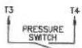
REMOTE CONNECTIONS

| CONTACT POSITION | |||||
| A | B | C | D | ||
| SWITCH POSITION | 1 | X | X | ||
| 1+2 | X | X | |||
| 2 | X | X | |||
SELECTOR SWITCH ARRANGEMENT.
9. SPECIFICATIONS.
| Model | HY55200-3 | HY75270-3 |
| Voltage - V | 400 | 400 |
| Number of phases | 3 | 3 |
| Frequency – Hz | 50 | 50 |
| Connecon method/Cable length m | Hard wired - 3 pin + earth industrial plug | Hard wired - 3 pin + earth industrial plug |
| Motor power hp/kw | 5.5/4 | 7.5/5.6 |
| Rated Speed (motor) – RPM | 2800 | 2800 |
| Maximum Pressure - PSi/Bar | 145/10 | 145/10 |
| Cut-out Pressure - PSi/Bar | 120/8.3 | 120/8.3 |
| Cut-in Pressure - PSi/Bar | 87/6 | 87/6 |
| Tank Capacity - L | 200 | 270 |
| Free air delivery - CFM - L/min | 16.5/476 | 21/595 |
| Displacement - CFM/L/min | 23/651 | 29/821 |
| Air Outlet | Valve Tap/ 1/2 " BSP | Valve Tap/ 1/2 " BSP |
| Output pressure regulaon type | Fixed | Fixed |
| Drive type | Belt | Belt |
| Overall Unit Dimensions L x W x H mm | 1520 x 480 x 940 | 1600 x 500 x 1040 |
| Net Weight - kg | 126 | 135 |
| Tank material | Rolled steel | Rolled steel |
10. DECLARATIONS of CONFORMITY.
Compressor models HY55200-3 & HY75270-3
Designed & produced in accordance with the following
• Machinery Directive 2006/42/EC
• Supply of Machinery (Safety) Regulaons 2008
• Supply of Machinery (Safety) Amendment Regulations 2011
• EU Directive 2000/14/EC (2005/88/EC)
Apply to air receiver:
• Simple Pressure Vessels Direcve 2009/105/EC
- Simple Pressure Vessels (Safety) Regulaons 1991
- Simple Pressure Vessels (Safety) Amendment Regulaons 1994
• EN286-1 Unred Pressure Vessels
Apply to safety valve:
• Pressure Equipment Directive 1997/23/EC
• The Pressure Equipment Regulaons 1999
• ISO 4126;.1 Safety Valves Part 1
11. DECLARATIONS of CONFORMITY.

Products which are labelled with the adjacent symbol MUST NOT be disposed of in household rubbish. You must dispose of packaging and old electrical and electronic equipment separately.
11.1 Disposing of packaging.
10.1.1 The packaging consists of cardboard and correspondingly marked plascs that can be recycled.
10.1.2 Recycle all packaging materials.
11.2 Disposing of appliance (at end of life).
10.2.1 Please check with your local authority about the possibilities for correct disposal.
12. WARRANTY
To register your product for the manufacturer's warranty, please visit:
hps://hyundaipowerequipment.co.uk/warranty
NOTES
For Inquiries, Please Contact:
GENPOWER LTD
Isaac Way, London Road
Pembroke Dock, UNITED KINGDOM, SA72 4RW
T: +44 (0) 1646 687 880 F: +44 (0) 1646 686 198
E: info@hyundaipowerequipment.co.uk
www.hyundaipowerequipment.co.uk



- 3 Phase electric air compressor HY55200-3 & HY75270-3
- Contents
- Introduction
- N.b. warning
- Installation
- 2.1 Portable compressors
- 2.2 2 Staonary compressors
- N.b. minimum working temperature +5°C
- Electrical notes
- Tandem/duplex compressors
- Installation
- Caution
- Start up
- Maintenance
- 6.1 Cleaning and changing lter cartridge
- 6.2 General maintenance
- 6.3 Oil
- 6.4 Oil change
- 6.5 Emergency stop buon (tandem only)
- 6.6 How to x minor faults
- 6.7 How to x it. (fig. 18)
- 6.8 The compressor runs but does not produce air
- Warning
- 6.9 If the compressor is used for painng
- Pressure switchadjustments
- MDR-3 three phase
- Attention
- Electrical connections
- Electric motor terminal board connection
- Specifications
- Declarations of conformity
- Declarations of conformity
- 11.1 Disposing of packaging
- 11.2 Disposing of appliance (at end of life)
- Warranty
Brand : HYUNDAI
Model : HY55200-3
Category : Compressor