FSW - Système de rails pour portes vitrées Dormakaba - Free user manual and instructions
Find the device manual for free FSW Dormakaba in PDF.


| Product Type | Folding sliding wall system (FSW) |
| Brand | Dormakaba |
| Model | FSW |
| Track Rail Dimensions | 75 x 72 mm |
| Glass Panel Insertion Depth (Upper Rail) | 25 mm |
| Height Adjustment Range | Up to 5 mm extra by decreasing glass insertion depth in lower rail |
| Floor Clearance | 10 mm (adjustable) |
| Distance: Top of Adapter Profile to Bottom of Track Rail | 33.5 mm (after adjustment) |
| Track Rail Fixing Interval (Stacking Area) | Approx. 100 mm |
| Track Rail Fixing Interval (Remaining Sections) | Approx. 300 mm |
| Lock Mechanism Type | Upper lock and bottom lock with strike plate/eccentric bushing |
| Bottom Lock Adjustment | ±4 mm (strike plate), ±2.5 mm (eccentric socket) |
| Brush Seal | Upper brush profile inserted into adapter profile |
| Panel Installation | Via track rollers and hinge pins |
| Material | Aluminum track, steel substructure, glass panels |
| Operation | Manual folding/sliding |
| Maintenance | Regular cleaning of locks and floor keeps; ensure bolts in good order |
| Included Accessories | Lock mechanism, drilling template, shims, cover profiles, glass knob |
| Required Tools | Allen keys (5 mm, 6 mm), spanners (17 mm), drill |
| Safety Notes | Support panels during installation; ensure proper alignment to avoid floor contact |
Frequently Asked Questions - FSW Dormakaba
User questions about FSW Dormakaba
0 question about this device. Answer the ones you know or ask your own.
Ask a new question about this device
Download the instructions for your Système de rails pour portes vitrées in PDF format for free! Find your manual FSW - Dormakaba and take your electronic device back in hand. On this page are published all the documents necessary for the use of your device. FSW by Dormakaba.
USER MANUAL FSW Dormakaba
FSW Installation instructions
Track rail 75 x 72 mm
1. Ceiling substructure and installation of the track rail (Fig. 1):
The track rail must be bolted over its entire length (including the stacking track area) to a correctly aligned ceiling substructure of steel. The steel substructure should be designed to accommodate the total weight of all the panels. The substructure fixing point intervals for the track rail should be approx. 100 mm in the stacking area and approx. 300 mm along the remaining track sections. The maintenance end piece (a) can be detached for panel installation, removal and servicing.

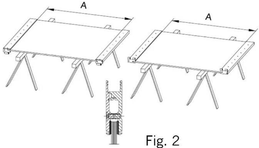
2. Fitting the hinged door rails to the glass panel (Fig. 2):
The door rail with either a panel hinge section or a frame hinge section consists of two profile sections which are bolted together. (In order to avoid scratching, the cover profiles are clipped on only after the system has been completely installed.) Slightly loosen the screws on the hinges and the door rails. Slide the upper door rail onto the glass and clamp tightly. Glass insertion length: 25 mm. It is particularly important to clamp the upper door rail correctly due to its bearing function. If the system is likely to be subjected to vibration, silicone must be applied to the glass panels at the upper door rail for added adhesion at the clamped connection.
Slide the lower door rail onto the glass and align it with the upper door rail. When aligning the door rails, ensure that measurement A is the same for each folding panel.
A = total height of the system -353 mm.
After aligning the door rails, firmly tighten the M8 hex socket screws on both sides so that the rails clamp the glass securely. (5 mm Allan key, tightening torque 20 Nm)
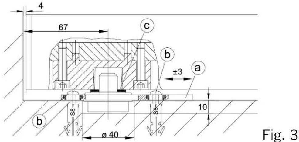
3. Lower floor pivot assembly for the pivoting end panel (Fig. 3):
The distance from the pivot point to the wall (67 mm) can be corrected by adjusting the floor pivot (a) as follows:
Loosen both fixing screws (b).
Adjust the position of the floor pivot and re-tighten the screws. Adjust the height using the shims provided (c) (3 shims of 1 mm thick each).
4. Installing the folding end panel (Fig. 4):
Slide the upper pivot assembly (a) of the end panel into the end of the track rail.
Securely clamp the pivot assembly (using a 6 mm Allan key) in position at a distance of 67 mm from the wall. Install the floor pivot directly underneath the upper pivot assembly with a distance of 67 mm between the pivot point and the wall (Fig. 3.1). Wind down the bolt (b). Insert the end panel with bolt (b) in the upper pivot assembly (Fig. 4.2), align vertically and set down on the floor pivot (Fig. 4.3). Turn bolt (b) until it comes into contact with rollpin (f), then turn it back one revolution (1 mm clearance); tighten nut (d) using a 17 mm spanner.
Next firmly tighten the set screw in the suspension block (c) using a 5 mm Allan key.
Fix securing plate (e) with bolt (g) onto the upper pivot assembly.
Fig. 4.1 Fig. 4.2 Fig. 4.3

Fig. 4

natural_image
Technical cross-sectional diagrams of mechanical components, showing internal assembly and alignment views (no text or labels)5. Threading the panels onto the track (Fig. 5):
The second and fourth panels are provided with a roller (a) (Fig. 5.1). Detach the maintenance end piece. Slide the track rollers into the track rail and re-connect the maintenance end piece. If a folding end panel has already been installed, loosen the set screws (b) in the top and bottom hinges and remove pins (c) (Fig. 5.2).
Connecting the next folding panel:
Insert a 10 mm spacer block (d) underneath the lower door rail (Fig. 5.3). Slide the suspension block (e) 65 mm from the panel edge into the adapter profile. The set screw (f) must point outwards. Loosely tighten the 17 mm M12 nut (g) (Fig. 5.4). Slide together the frame hinge section (h) and the panel hinge section (i) at both the top and the bottom of the panel and secure with pin (c). Ensure that the folding panels are positioned at the same height and secure pin (c) with set screw (b) (Fig. 5.2). Before mounting the next folding panel, support the system from below, e.g. using wooden wedges, and then proceed as described above. (Tip: the third panel must be supported with particular care, as it is installed without a track roller for suspension.)
Aligning the panel height:
The height of the panels must be aligned to create a 10 mm clearance between the floor and the lower door rail. Ensure that the distance between the top surface of the adapter profile and the bottom surface of track rail is 33.5 mm. To adjust the height of the panels, loosen nut (l) using a 17 mm spanner.
Adjustments are made at nut (k) using a 17 mm spanner (Fig. 5.3):
Counter-clockwise rotation = more floor clearance
Clockwise rotation = less floor clearance
Next firmly tighten nut (l).
Note: If the height adjustment as described is not sufficient, the distance that the glass inserted into the lower door rail can be decreased in order to achieve an extra 5 mm.
Afterwards fold up the FSW system and align the position of the rolls by an adjusting device so that all panels stand rectangular to the track rail axis and the panels do not come in contact with the floor. After aligning adjust the track rolls with nut (l) firmly at bearing profile.
Now the system can be closed again. Clip on the cover profiles and mount the control buttons of the lower front door bolt.
Screw the glass knob (m) onto the folding end panel. In the case of a 4-panel system, screw an additional glass knob onto the third folding panel (Fig. 5.1).


Fig. 5.4

Fig. 5

6. Installing the upper lock mechanism (Fig. 6):
The lock mechanism (a) and (c) is supplied complete in the accessories pack.
Tapped holes for the top section (a) are provided in the track rail.
Fix the top section (a) of the lock mechanism, insert the lock bolt (b) into the top section, ensure that it is straightened and then drill two 8 – 10 mm dia. holes (d) at a distance of 22 mm from the top surface of the bearing profile. Fix the bottom section (c) with backplate onto the bearing profile. Press the four plugs into the drilled holes (d).
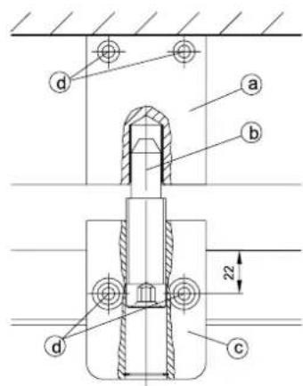
Fig. 6
7. Bottom lock (Fig. 7):
Position the panel by moving it into its end position and then ensuring that it is properly aligned. Slide the drilling template provided under the lock module and extend the locking pin so that the centre bore can be aligned to its location. Check the position once again and then secure the drilling template (e.g. by holding firmly in position by hand or foot). Retract the locking pin and move the panel away.
The position of the eccentric bushing or strike plate can then be properly marked through the drilling template and then the holes can be drilled.
Mount the strike plate/keep (eccentric socket) as appropriate. (For exact positioning, strike plate and keep can be adjusted ± 4 mm and ± 2.5 mm respectively.) Then bring the panel into position and lock. Then bring the next panel into position.

natural_image
Technical line drawing of a mechanical assembly with mounting bracket and mounting holes (no text or symbols)8. Installing the eccentric bushings (Fig. 8):
Mark the requisite positions of the eccentric bushings plumb below the lock bolts of the panels.
Version a) Drill holes 25 mm dia., 30 mm deep for eccentric bushings, and 8 mm dia. for anchor plugs. Insert eccentric bushings (double eccentric), align and fix with central screw in anchor plug (Figs. 8.1 and 8.2)
Version b) Mount the eccentric bushings in continuous recessed channel (Fig. 8.3)

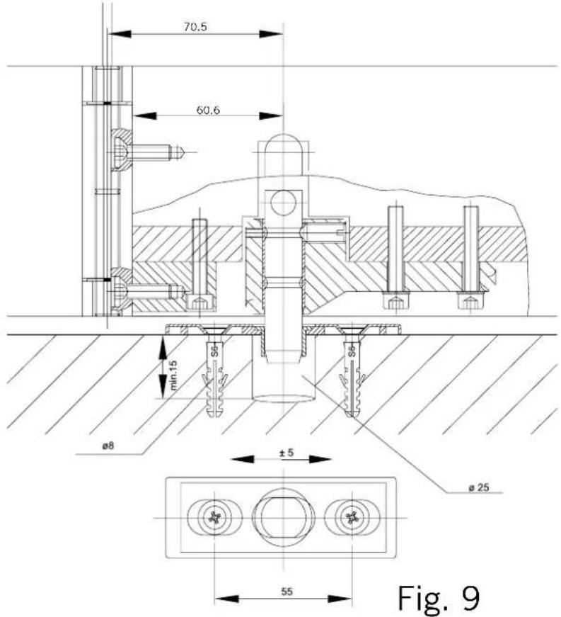
9. (Alternative to 8.) Installing adjustable strike plate (Fig. 9):
Mark out the drill holes as per Section 7. and drill 25 mm dia. holes at least 15 mm deep. In addition, drill 8 mm dia. holes spaced 55 mm apart for anchor plugs. Mount the strike plate. Bring the panel into position and lock.
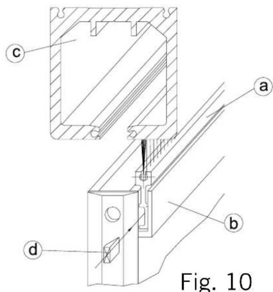
10. Mounting the upper brush seal (Fig. 10):
Insert the brush profile (a) into the upper adapter profile (b) and align so that the brush is in contact with the track rail profile (c). Secure the brush profile on the left and right with a plastic wedge (d). Clip on the cover profiles.
System maintenance
In order to ensure functional reliability over the long term, please comply with the following instructions:
- Ensure that locks and bolts are kept in good working order.
- Regularly clean keeps for locks and bolts located in the floor.
- FSW Installation instructions
- Ceiling substructure and installation of the track rail (Fig. 1):
- Fitting the hinged door rails to the glass panel (Fig. 2):
- Lower floor pivot assembly for the pivoting end panel (Fig. 3):
- Installing the folding end panel (Fig. 4):
- Threading the panels onto the track (Fig. 5):
- Connecting the next folding panel:
- Aligning the panel height:
- Installing the upper lock mechanism (Fig. 6):
- Bottom lock (Fig. 7):
- Installing the eccentric bushings (Fig. 8):
- (Alternative to 8.) Installing adjustable strike plate (Fig. 9):
- Mounting the upper brush seal (Fig. 10):
- System maintenance
Brand : Dormakaba
Model : FSW
Category : Système de rails pour portes vitrées