
DHY22KSEm - Generator HYUNDAI - Free user manual and instructions
Find the device manual for free DHY22KSEm HYUNDAI in PDF.


| Product Type | Generator |
| Brand | Hyundai |
| Model | DHY22KSEm |
| Power Output | 22 kVA (22 kW standby) |
| Fuel Type | Diesel |
| Engine | Hyundai 4-stroke, single cylinder |
| Displacement | 500 cc |
| Starting System | Electric start with recoil backup |
| Voltage | 230 V AC, 50 Hz |
| Phase | Single phase |
| Fuel Tank Capacity | 25 liters |
| Run Time at 50% Load | 12 hours |
| Noise Level | 78 dB(A) at 7m |
| Dimensions (L x W x H) | 900 x 600 x 700 mm |
| Dry Weight | 180 kg |
| Fuel Consumption | 2.5 L/h at full load |
| Oil Capacity | 1.5 liters |
| Oil Type | SAE 15W-40 |
| Cooling System | Air-cooled |
| Emissions Compliance | EPA Tier 4 |
| Warranty | 2 years limited |
Frequently Asked Questions - DHY22KSEm HYUNDAI
User questions about DHY22KSEm HYUNDAI
0 question about this device. Answer the ones you know or ask your own.
Ask a new question about this device
Download the instructions for your Generator in PDF format for free! Find your manual DHY22KSEm - HYUNDAI and take your electronic device back in hand. On this page are published all the documents necessary for the use of your device. DHY22KSEm by HYUNDAI.
USER MANUAL DHY22KSEm HYUNDAI
1500RPM DIESEL GENERATORS
User Manual
natural_image
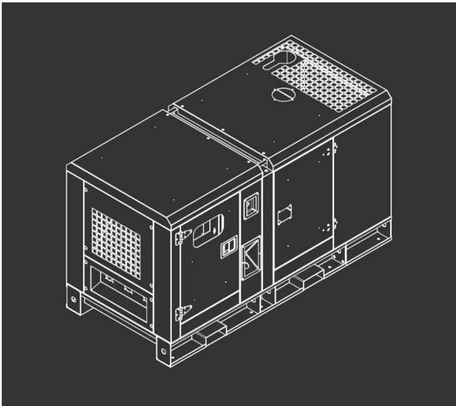
Technical line drawing of an electronic device chassis with ventilation grilles and mounting brackets (no text or symbols)CONTENTS
Page/s
-
SAFETY & SAFETY LABELS 3 - 12
-
GENERAL USAGE INFORMATION 13 - 14
-
MAIN PARTS 14 - 20
-
COMPONENT LOCATIONS 21 - 22
-
INSTALLATION 23 - 33
-
OPERATION 34 - 42
-
MAINTENANCE 42 - 46
-
WIRING DIAGRAM 47 - 48
-
USEFUL FORMULAE 49
-
ELECTRICAL INSTALLATIONS WITH OPTIONAL EQUIPMENT 50 - 58
-
REMOTE CONTROL 59 - 61
-
DECLARATIONS of CONFORMITY 62
-
CONTACT DEATILS 62
-
MANUAL UPDATES 62
-
WARRANTY 62
1. SAFETY & SAFETY LABELS.
1.1. General safety notes.
1.1.1. The operator of the machine is responsible for, and has a duty of care in making sure that the machine is operated safely and in accordance with the instrucons in this user manual. Keep the manual safe and pass it on if the machine is to be loaned/sold to another user.
1.1.2. Please note the following safety points.
1.1.2.1. The machine should never be le it in a condion which would allow an untrained or unauthorised person/s to operate this machine.
1.1.2.1.1. All due care and diligence should be taken by the operator for the safety of and with regard to those around whilst using the machine.
1.1.2.1.2. Some or all of the following - warning signs, symbols and/or PPE pictograms may appear throughout this manual. You MUST adhere to their warning/s. Failure to do so may result in personal injury to yourself or those around you.
| The FOLLOWING safety notes will help avoid or reduce risk of injury or death. | |||||||
| !DANGERIndicates a hazard, which, if not avoided, could result in serious injury or death. | !WARNINGIndicates a hazard, which, if not avoided, could result in serious injury. | !CAUTIONIndicates a hazard which, if not avoided, might result in minor or moderate injury. | |||||
| !NOTEIndicates a situaon that could easily result in equipment damage. | READ & Keep the manual safe and pass it on if the machine is to be loaned/sold to another user. | You MUST fully read the instrucons to make sure you use and operate machine safely | |||||
| Appropriate Personal Protective Equipment (PPE)MUST be worn at all mes when machine is in use or being repaired. | |||||||
 |  |  |  |  |  |  |  |
| ALWAYS keep the working area clear of non-essenal people to include but not limited to children, the elderly and vunerable persons. NEVER ALLOW an untrained person to use this machine. | |||||||
1.2. Carbon monoxide.
1.2.1. Carbon monoxide is a colourless and odourless gas. Inhaling this gas can cause death as well as serious long term health problems such as brain damage.
1.2.2. The symptoms of carbon monoxide poisoning can include but are not limited to the following;
Headaches, dizziness, nausea, breathlessness, collapsing or loss of consciousness.
1.2.2.1. Carbon monoxide poisoning symptoms are similar to u, food poisoning, viral infecons and simply redness. It is quite common for people to mistake this very dangerous poisoning for something else.
1.2.2.2. To avoid carbon monoxide poisoning DO NOT use Petrol/Diesel-powered equipment inside any of the following;
Home, garage, tent, camper van, mobile home, caravan or boat.
This list is not exhaustive and if you are in any doubt contact your dealer.
1.2.3. If you think you have or someone around you has been aected by carbon monoxide poisoning;
1.2.3.1. Get them fresh air immediately, by leaving the aected area or by opening doors and windows. If safe and praccal to do so make sure that the machine is turned o. DO NOT enter a room you suspect of having carbon monoxide present – instead call the emergency services.
1.2.3.2. Contact a doctor immediately or go to hospital - let them know that you suspect carbon monoxide poisoning.
1.2.4. DO NOT use in an enclosed area or a moving vehicle.

1.1. General fuel safety.
1.1.1. Fire hazard - keep fuel away from all sources of ignition for example heaters, lamps, sparks from grinding or welding.

Fire Hazard
1.1.2. DO NOT carry out hot work on tanks that have contained fuel it is extremely dangerous
1.1.3. ALWAYS keep work area clean and dy.
1.1.4. ALWAYS clean up all spills promptly using correct methods i.e. absorbent granules and a lidded bin.
1.1.5. ALWAYS Dispose of waste fuels correctly.
1.2. Fuelling/De-fuelling.

CAUTION
ALL FUELS ARE FLAMMABLE
1.2.1. ALWAYS fuel and defuel in a well-venlated area outside of buildings.
1.2.2. ALWAYS wear correct, suitable and t for purpose Personal Protective Equipment (PPE), suggested items are but not limited to safety gloves and overalls.

1.2.3. When fuelling/de-fuelling ALWAYS avoid inhaling fumes
1.2.4. When de-fuelling ALWAYS use a propriety fuel retriever.
1.2.5. ALWAYS carry fuel in the correct and clearly marked container.

Fire Hazard
1.3. Electrical safety.

Risk of
electric shock
1.3.1. Electricity can kill - NEVER work on LIVE/ENERGISED equipment.
1.3.2. Prior to carrying out any maintenance work you MUST Identify electrical isolaon methods and isolate all electrical supplies,
1.3.3. Prior to use and with all electrical supplies isolated You MUST check all electrical cables, plugs and connecons for the following;
1.3.3.1. Cables are intact and have no signs of damage, to include but not limited to bare wires, chang, cuts and loose wiring.
1.3.3.2. If there are any signs of damage, the damaged item MUST be taken out of service until the damage has been repaired by an electrically competent person.
1.3.3.3. All trailing cables should be routed so as not to cause any kind of trip hazard.
1.3.3.4. NEVER work on or near electricity with wet hands, wet clothing, and wet gloves.
1.4. Baeries.

Corrosive
1.4.1. Baeries are risk if they become damage by the possible leaking of electrolyte. This electrolyte is an acidic and can cause serious burn injuries. Care should be taken when working on or near them. NOTE the electrolyte may be in liquid or gel form.
1.4.2. Should you come into contact with electrolyte you should;
1.4.2.1. Remove all clothing contaminated with electrolyte. If you cannot remove then saturate in water.
1.4.2.2. Get medical assistance as soon as possible. You must advise the medical sta of the type acid.
1.4.2.2.1. Lead/acid baery = dilute sulphuric acid
1.4.2.2.2. Nickel/cadmium = potassium hydroxide alkali electrolyte.
1.4.2.3. Use fresh running water to wash o excess electrolyte, connue this unl medical assistance arrives. Make sure that you do not wash the electrolyte to another part of the face or body.
1.4.2.4. If electrolyte comes into contact with Eyes the electrolyte needs to be immediately washed away with large amounts of water. Make sure that you do not wash the electrolyte to another part of the face or body.
1.4.3. Gasses from charging baeries are highly ammable and great care should be taken to charge in well venlated areas.
1.4.4. There is an explosion risk if the baery terminals are short circuited, when connecng/dis-connecng ALWAYS exercise great care so that the terminals or baery leads are NOT allowed to touch. ALAWYS use suitable insulated tools.

Risk of explosion
1.5. Noise.
1.5.1. The operang noise of the machine can damage your hearing. Wear hearing protecon such as earplugs or ear defenders to protect your hearing. Long-term and regular users are advised to have hearing checked regularly. Be especially vigilant and cauous when wearing hearing protecon because your ability to hear alarm warnings will be reduced.
1.5.2. Noise emissions for this equipment is unavoidable. Carry out noisy work at approved mes and for certain periods. Limit the working me to a minimum. For your personal protecon and protecon of people working nearby it is also advisable for them to wear hearing protecon.
1.5.3. See CERTIFICATE of CONFORMITY secon for Outdoor Noise declaraon of conformity.

1.6. Safety.
1.6.1. Before operang and maintaining this generator set. Please read this manual and make sure you understand this operaon and maintenance manual and other documents which are aached to the engine.
1.6.2. Correct installaon of the generator set is the precondition of normal operaon. Only genuine Hyundai spare parts should be used. Failure to do so will invalidate your warranty.
1.6.3. A properly maintained machine will ensure good running conditions and improve life expectancy of the generator sets.
1.6.4. The generator set must only be operated by the persons who have received training on its operaon. Only authorised and trained persons should carry out maintenance and repairs to this machine.
1.6.5. Operators and maintainers should make sure they are familiar with all safety, preventive acons and operational maintenance procedures.
1.6.6. The generator sets can only be started under safe conditions. Please do not start the generator sets when any abnormal conditions been found this will help to avoid accidents.
1.6.7. Shut down the machine before cleaning, maintaining and repairing the generator set. Remove the negave baery connecn on and prevent it from accidentally connecng to any other part/s of the machine. Place a warning label/sign to say machine is being worked on, this will help in avoiding accidents.
1.6.8. The exhaust air discharged from engine is harmful to people's health.
1.6.9. All of the generator sets installed indoors must have a correctly installed exhaust system to vent all such gasses to the outside of the building.
1.6.10. Whilst the generator set running, the exhaust pipe and silencer will become very HOT. Therefore when a generator set is installed, these parts need to be covered with re retardant insulaon materials and be kept far away from inammable materials. This needs to be maintained at all mes.
1.6.11. Please make sure good that venlaon has been planned and installed to vent exhaust gasses eecvely from the generators locaon.
1.6.12. DO NOT place ammable materials and fuels near the engine.
1.6.13. DO NOT smoke, or allow any naked ames or sparks in the vicinity of charging baeries. Whilst baeries are charging they can vent highly explosive hydrogen and oxygen gasses.
1.6.14. Suitable re exnguishers should be ed in the vicinity of a generator installaon and all users and maintainers should be trained in their use.
1.6.15. Where the fan protecon cover or other protecon covers have been removed DO NOT run the generator set. If the generator set has to be started YOU MUST make sure that you keep your ngers, hands, arms, long hair, jewellery and loose clothing away from fan belt, pulley and other moving parts.
1.6.16. When working in the generator set installaon room, YOU MUST wear appropriate personal protective clothing.
1.6.17. When the generator set is running DO NOT try to open the radiator cap. The coolant will be under pressure and extremely hot. If this is done you place yourself at serious risk of injury from scalding and burns.
1.6.18. Before lling with an-freeze YOU MUST allow the generator and radiator to fully cool down.
1.6.19. DO NOT swallow or let your skin come into contact with the harmful materials such as fuel, an-freeze, lubricant and electrolyte.
1.6.20. If you swallow any of these liquids seek urgent medical advice. In most cases YOU MUST NOT induce vomiting.
1.6.21. If you come into contact with any of these kinds of liquids, YOU MUST use plenty of clean water to rinse o the aected area. YOU MUST make sure that you wash away from the aected area but avoid spreading to non-aected parts.
1.6.22. YOU MUST avoid working in high noise level environment it will cause harm to your hearing. If you have to work in the vicinity of a running generator set YOU MUST wear correct hearing protecon.
1.6.23. Whenever the generator set needs to be connected to output power, the cabling must conform to the conditions, specicaon and standard related to power distribuon.
1.6.24. When the installation of generator set is involved in any welding. DO NOT connect to the ground circuit or make grounding through generator set or engine.
1.6.25. This will avoid the current being generated from welding operaon damaging the electronics within the control panel, bearings and bearing bush etc. inside of the generator set.
1.6.26. YOU MUST make sure the generator set is suitably bonded to earth.
1.7. Safety Labels.
1.7.1. Warning signs and symbols.
1.7.1.1. Transport Warning.
1.7.1.1.1. Never li the generang set by aaching to the engine or alternator liing lugs, instead use the liing points on the base frame
or canopy. Make sure that the liing rigging is in date for use and that the supporting structure is in good condition and has a capacity suitable for the load.
1.7.1.1.2. Keep all personnel away from the generang set when it is suspended. DO NOT allow anyone to walk under a suspended machine.

1.7.1.2. Mechanical Warning.
1.7.1.2.1. DO NOT aempt to operate the generang set with the safety guards removed.
1.7.1.2.2. While the generang set is running do not aempt to reach under or around the guards to do maintenance or for any other reason.
1.7.1.2.3. Keep hands, arms, long hair, loose clothing and jewellery away from pulleys, belts and all other moving parts.

1.7.1.2.4. Safeguard Warning.
1.7.1.2.4.1. Generang sets that are not equipped with sound aenuang enclosures can produce noise levels in excess of 105 dB (A). Prolonged exposure to noise levels above 85 dB (A) is hazardous to hearing.
1.7.1.2.4.2. Wear protecve clothing including hearing protecon, gloves and hat when working around the generang set.

1.7.1.3. Access doors - Hot surfaces.
1.7.1.3.1. If equipped keep access doors on enclosures closed and locked when not required to be open.
1.7.1.3.2. Avoid contact with hot oil, hot coolant, hot exhaust gases, hot surfaces and sharp edges and corners.

1.7.1.4. Gas & Fume Warnings.
1.7.1.4.1. Ensure that the generang set room is properly venlated.
1.7.1.4.2. Keep the room, the oor and the generang set clean. When spills of fuel, oil, baery electrolyte or coolant occur, they should be cleaned up immediately.
1.7.1.4.3. NEVER store ammable liquids near the engine.
1.7.1.4.4. Do not smoke or allow sparks, ames or other sources of ignition around fuel or baeries. Fuel vapours are explosive. Hydrogen gas generated by charging baeries is also explosive.
1.7.1.4.5. NEVER store ammable liquids near the engine.
1.7.1.4.6. DO NOT smoke or allow sparks, ames or other sources of ignition around fuel or baeries.
1.7.1.4.7. Fuel vapours are explosive. Oxygen and Hydrogen gases generated by charging baeries are explosive.


1.7.2. Electrical Warning.
1.7.2.1. DO NOT touch electrically energized parts of the generang set and/or interconnecng cables or conductors with any part of the body or with any non-insulated conducve object.

1.7.3. Terminal box covers.
1.7.3.1. Replace the generang set terminal box cover as soon as conncon or disconncon of the load cables is complete.
1.7.3.2. DO NOT operate the generang set without the cover securely in place.
1.7.3.3. Connect the generang set only to loads and/or electrical systems that are compatible with its electrical characteriscs and that are within its rated capacity.
1.7.3.4. Keep all electrical equipment clean and dry. Replace any wiring where the insulaon is cracked, cut, abraded or otherwise degraded. Replace terminals that are worn, dis-coloured or corroded.
1.7.3.5. Keep terminals clean and ght.

1.7.4. Earthing (Grounding).
1.7.4.1. You MUST make sure that the generator set is correctly connected to earth.

1.7.5. Connecng/disconnecng loads.
1.7.5.1. Prior to aempng to connect or disconnect loads The generator set should be shut down, and the baery negave (-) terminal disconnected.
1.7.5.2. NEVER aempt to connect or disconnect load connecons while standing in water or on wet or soggy ground.

Positive Negave
2. GENERAL USAGE INFORMATION
2.1. For - Connuous service.
2.1.1. The generator set can be used as main power supply to generate electricity for several purposes, e.g. lighng, heang etc.
2.2. For - Standby service.
2.2.1. The generator set can be used as standby power supply to provide connuous electric power for variable loads.
2.2.2. The generator set is suitable for the areas where you must provide a connuous power supply, such as hospitals, industrial facilities, airports etc.
2.3. For - Emergency service
2.3.1. The generator set can used as auxiliary power supply to solve energy interrupts that may cause serious problems to people, physical and/or nancial damage or to face consumption peaks.
2.3.2. The generator can be setup to start quickly to provide electric power for loads when the mains supply fails, and switch to stop aer the mains supply becomes normal. Generally the generator set can connue to run for several hours.
2.4. Under loading of Diesel Generators.
2.4.1. What is under loading?
2.4.1.1. The running of any diesel engine with no load or very light loads. In the industry this is also known as “wet-stacking”.
2.4.1.2. This can be due to facility or site managers not waning to risk interruptng daily business by transferring the true load to the generator, or data centres waning to protect their UPS baery warranty.
2.4.1.3. It could also be due to a generator being over specied when purchased, or a company that has downsized their electrical requirements.
2.4.2. Why is under loading a problem?
2.4.2.1. A diesel engine needs to operate under substanal load, to reach its opmum operang temperature. If it fails to reach this temperature then a percentage of the fuel will be unburnt and a build-up of soot can occur.
2.4.2.2. Within the engine, soot can cause internal glazing of the cylinder bores, scking of the piston rings, reducing compression and the injectors are likely to have a build-up of carbon causing more unburnt fuel to pass through the combuston chamber into the exhaust.
2.4.2.3. The rst sign of this problem is heavy smoke from the exhaust, eventually, the unburnt fuel will condense in the exhaust and mix with the
soot, to create a thick dark liquid that looks like engine oil. This liquid will seep from the exhaust, and will appear to be an oil leak. This liquid can build up in the exhaust silencer and there is the risk of it igning from the increased heat of the exhaust fumes, if the generator is subsequently put under full load.
2.4.2.4. If a generator connues to be operated with no load or very light load there is a possibility that permanent engine damage can occur.
2.4.3. How to avoid under loading.
2.4.3.1. When specifying a new generator, ensure that the unit is adequate for the requirement, without being too large.
2.4.3.2. If the machine is future proofed with additional capacity, or the exisng installaon is over capacity, a load bank tesng programme must be implemented.
2.4.3.3. The load bank should be used to create an arcial demand for between 75% and 100% of prime load and this, in most circumstances, will burn a carbon deposits, prolonging the life of the generator.
2.4.3.4. Typically the generator should be run at 75% of prime power for 2 hours in every 100 hours use.
2.4.4. If you need any further claricaon concerning generator under loading or misuse please call our technical sales team.
3. MAIN PARTS
3.1. Diesel Engine.
3.1.1. According to the dierent output power of each of our generator sets, we combine it with the best model of diesel engine to give the range of output power.
3.1.2. HYUNDAI Power chooses the diesel engines with rst class performance and high reliability.
3.1.3. HYUNDAI Power also pay special aenon to the technical advantage of engines in all aspects with a view to reduce exhaust gas emission, decrease fuel consumption rate and good noise level control.
3.2. Alternators.
3.2.1. Our alternators are single bearing self-excitao brushless alternators and have the following features;
3.2.1.1. Four polar brushless self-excitao, single bearing with insulaon class H and protecon level is IP22.
3.2.1.2. Stators are wound to 2/3 pitch, which eecvely eliminates/curbs triple waveform deformation of output voltage.
3.2.1.3. When in parallel with the mains or other generator sets, this type of winding can eecvely avoid excessive neutral currents and reduces inducve heat.
3.2.1.4. Before being assembled, the rotors need to pass dynamic balance tesng. The improved damper reduces voltage deviaon and heat under unstable load.
3.2.1.5. The exciter rotor output is fed to the main rotor through a three phase full wave bridge recer, the recer is protected by a surge suppressor against surges caused by short circuit or out-of-phase paralleling.
3.2.1.6. The Automac voltage regulator has the feature of automac load curtailment which is used to protect the engine, and make it possible to add full load to the alternator at one me. Steady state voltage adjusng rate can reach ±1% (under certain requirements, steady state voltage adjusng rate can meet ±0.5%). If PMG system is chosen, the motor will have high starng capacity and the ability of interference rejecon for the deformed voltage waveform fed by the main stator generated by nonlinear load(such as silicon control DC electric motor, UPS etc.).
3.2.1.7. Telephone inuence factor TIF<50, telephone harmonic wave factor THF<2%, the brushless style and high quality AVR ensures low interference with Radio.
3.2.2. Cooling system.
3.2.2.1. The engine is water cooled.
3.2.2.2. The water cooled system comprises of a radiator, a pusher fan and thermostat. The alternator has its own internal fan to cool the alternator components.
3.2.3. Electrical system.
3.2.3.1. The engine electrical system is 12 volt or 24 volts DC, negave ground/earth.
3.2.3.2. This system includes;
3.2.3.2.1. An electric engine starter motor.
3.2.3.2.2. A baery and a baery charging alternator.
3.2.3.2.3. For the 12 volt DC electrical system one baery is supplied. For 24 volt DC electrical system two lead-acid baeries are supplied.
3.2.4. Coupling.
3.2.4.1. Engine and alternator are rmly joined by a coupling cone that guarantees proper co-axial alignment.
3.2.4.2. Single-support machines use a special exible disk in place of a exible coupling.
3.2.5. Fuel tank and base frame.
3.2.5.1. The engine and alternator are coupled together and mounted on a heavy duty steel base frame.
3.2.5.2. This base frame includes a fuel tank with capacity of approximately 8 hours operaon under variable loads.
3.2.5.3. The tank is complete with lling cap and fuel level gauge and is connected by exible joints to the intake piping and to the overow pipe containing fuel from the injector drain.
3.2.5.4. The large capacity fuel tank is separate from generator set.
3.2.6. Control panel.
3.2.6.1. All models of HYUNDAI Power generator sets use a high grade control panel.
3.2.6.2. The core of control panel is an imported digital diesel engine control module, which has more complex funcons such as additional monitoring, user interface module, remote communicaon and protecon etc.
3.2.6.3. HYUNDAI Power generator set control panel is a steel plate structure, which ensures security and reliability, and the surface of it has been treated with stac powder painng. Which allows for easy cleaning.
3.2.6.4. Fied with locks to provide protecon against unauthorised use and has been designed for easy maintenance.
3.2.7. Oponal ngs for Canopied sets.
3.2.7.1. External anfreeze and coolant ller cap.
3.2.7.1.1. Our generator sets are ed with external anfreeze/coolant lling point.

3.2.7.1.2. When anfreeze has to be added, all the user has to do is open the anfreeze/coolant lling cap on the roof of canopy and the radiator's pressure valve cap to directly add anfreeze/coolant to the ller point and easily watch the an-freeze/coolant level.
3.2.7.2. Oil Change.
3.2.7.2.1. This range of generator sets have been ed with an oil change valve which connects directly to the outside of the canopy.
3.2.7.2.2. To empty oil place a receptacle to collect the old oil then open the oil discharge valve (see image on following page.

natural_image
Close-up of a mechanical component with a curved tool inserted, showing no visible text or symbols.3.2.7.3. Improved design for ease of transportaon.
3.2.7.3.1. Our canopied generator sets have been designed for ease of hoisng and transportaon.
3.2.7.3.2. Standard canopy sets are ed with a fork li holes on the base frame.
3.2.9. Other components.
3.2.9.1. The generator sets have other main components as listed but not limited too;
3.2.9.1.1. Starter motor.
3.2.9.1.2. Baery - Baery Cables.
3.2.9.1.3. Silencer – Corrugated pipe.
3.2.9.1.4. Exhaust elbow.
3.2.9.1.5. An-Vibraon mounts.
3.3 DEUTZ BF4M1013EC water pre-heater mechanical installaon instrucon schemac layout. (Oponal installaon).
3.3.1 On this machine take the cool water from the water pump and connect it to the water pre-heater. From the pre-water heater take the heated water to the oil cooling radiator.

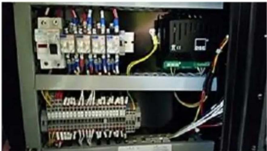
3.4 DEUTZ BF4M1013EC water pre-heater electrical wiring. (Oponal installaon).
3.4.1 The water pre-heater is fed from an external 230 VAC and should be supplied by a suitable RCD 13 Amp outlet and in accordance with BS7671:2008 Requirements for Electrical Installaons.
3.4.2 This conncon is made to three din mounted terminal blocks. These terminal blocks are ed by Genpower and are located at a suitable point within the control panel.
3.4.3 The live of this supply is fed to the Water pre-heater and the Baery charger via a normally closed contact of the Fuel Solenoid relay. N.B. Fuel solenoid contact is normally closed when engine is not running.
3.4.4 This allows the pre-water heater/baery charger to funcon whilst machine is not running thereby keeping engine warm and baeries fully charged.
3.4.5 The wiring to the pump is to be fed via exible conduit to the pump which is to be mounted at a suitable point.
Deutz BF4M1013EC
Water pre-heater
Electrical Wiring from terminal
block to heater

3.5 DEUTZ BF4M1013EC water pre-heater electrical schemac wiring from relay to baery charger and water heater. (Oponal installaon).
3.5.1 This schemac wiring shows the typical wiring.
3.5.2 Use a minimum of 1.5 mm2 wiring throughout.

flowchart
graph TD
    A["Deutz BF4M1013EC Water pre-heater Electrical Schematic Wiring from Relay to Battery Charger and Water Heater"] --> B["Fuel Solenoid Relay Normally Closed - When engine not running"]
    B --> C["To Battery Charger"]
    B --> D["To Water Heater"]
    B --> E["230VAC in"]
3.6 1500 RPM water pre-heater mechanical installaon instrucon (generic). (Oponal installaon).
3.6.1 On all 1500 rpm machines take the cool water from engine block drain as shown and connect it to the water pre-heater. From the pre-water heater take the heated water to the water pump inlet plug.
1500 RPM
Water pre-heater
Mechanical Installation
Instruction (Generic)

3.7 1500 RPM machines water pre-heater electrical wiring from terminal block to heater (generic). (Oponal installaon).
3.7.1 The water pre-heater is fed from an external 230 VAC and should be supplied by a suitable RCD 13 Amp outlet and in accordance with BS7671:2008 Requirements for Electrical Installaons.
3.7.2 This conncon is made to three din mounted terminal blocks. These terminal blocks are ed by Genpower and are located at a suitable point within the control panel.
3.7.3 The live of this supply is fed to the Water pre-heater and the Baery charger via a normally closed contact of the Fuel Solenoid relay. N.B. Fuel solenoid contact is normally closed when engine is not running.
3.7.4 This allows the pre-water heater/baery charger to funcon whilst machine is not running thereby keeping engine warm and baeries fully charged.
3.7.5 The wiring to the pump is to be fed via exible conduit to the pump which is to be mounted at a suitable point.
1500 RPM machines
Water pre-heater.
Electrical wiring from terminal block to heater (Generic)
natural_image
Interior view of an electrical control cabinet with visible wiring and circuit components (no readable text or symbols)4. COMPONENT LOCATIONS
4.1. Viewed from control panel – canopy removed.
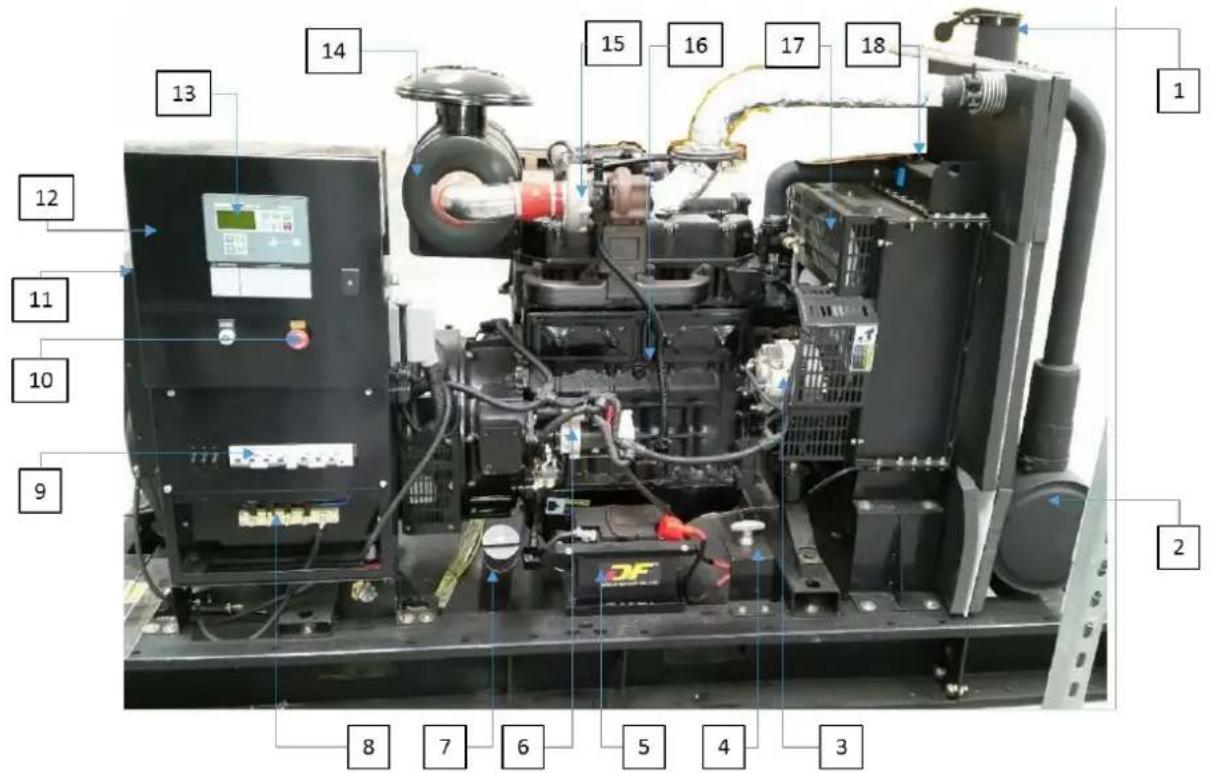
1 – Exhaust
4 - Baery isolator
7 - Fuelller cap
10 – Emergency stop buon
13 - MRS 10 panel
16 – Engine
2 – Silencer
5 - Baery
8 - Generator output
11 - Main alternator
14 - Air Iter
17 - Cooling fan
3 – Engine alternator
6 - Starter motor
9 - Main MCB's
12 - Control panel
15 - Turbo fan
18 - Radiator Iler cap
4.2. Viewed from reverse of control panel – canopy removed.
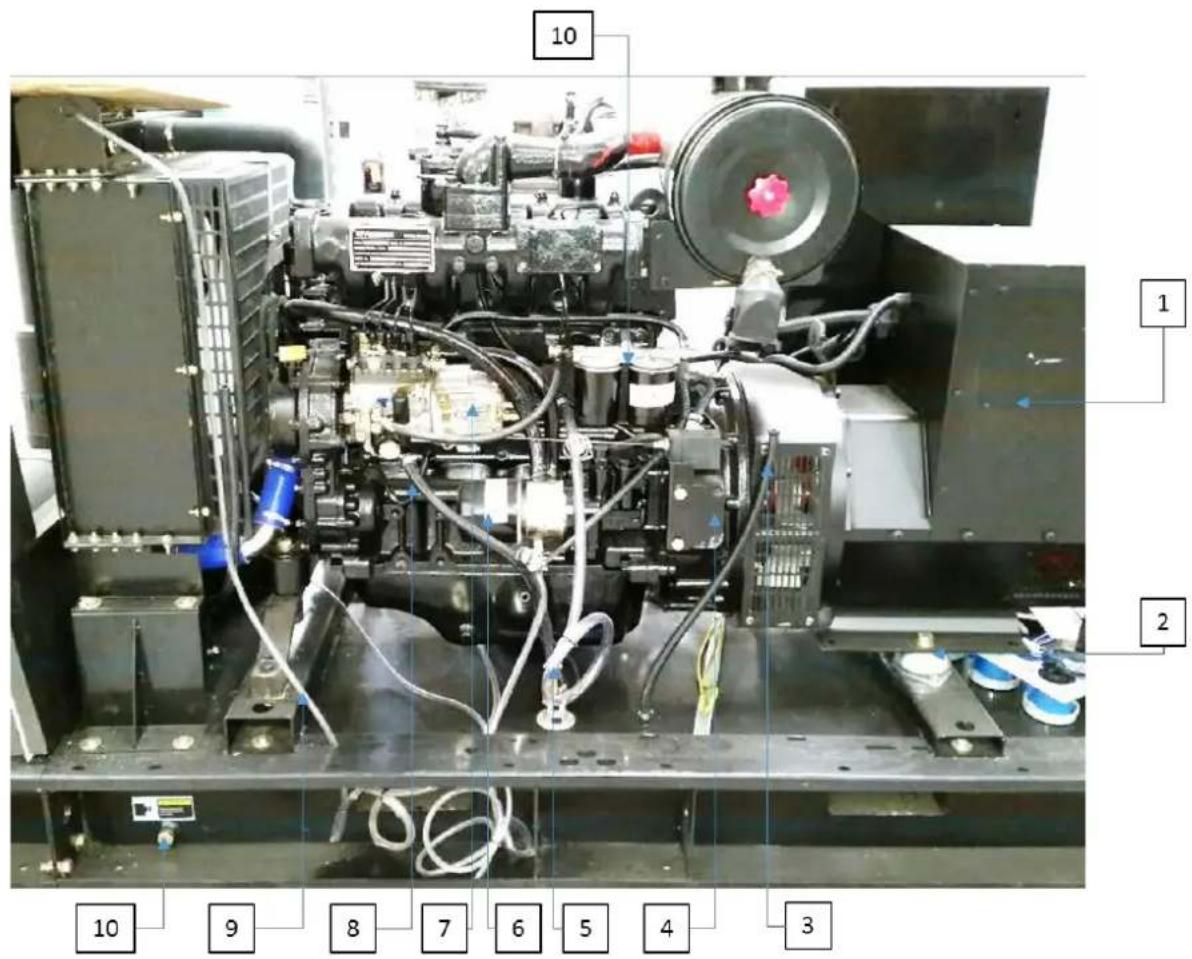
1 – Alternator
4 – Electronic governor
7 - Mechanical governor
10 – Fuel tank drain plug
2 – Resilient mount
5 – Engine coolant drain
8 - Fuel pick-up pipe
11 - Fuel Iters
3 – Fuel tank breather pipe
6 - Oil Iter
9 – Radiator drain pipe
5. INSTALLATION
5.1. General outline.
5.1.1. Correct installaon of generator set is the precondition which allows for the normal working status of the generator set.
5.1.2. The room set aside for the generator set shall be designed specially to meet the expected funcons and maintenance operaons, and at the same me the design of generator set working room shall conform to all local building and any other applicable regulaons.
5.2. Transportaon.
5.2.1. During shipment, the generator must be protected against vibraon, secured ghtly to the transport vehicle. This will protect against components being shaken loose.
5.2.2. During shipment of the generator set, nothing should be placed above the generator set as this will avoid damage caused by such weights.
5.2.3. When loading or unloading the generator set a forkli or hoisng device shall be used to avoid the generator set become lted or falling to the ground, which may cause damage.
5.2.4. Liing holes have been designed on the common base frame of our generator sets. Some of the specially designed generator sets have been ed with liing holes on the roof and forkli openings on the base frame etc.
5.2.5. Users can transport the generator set according to the guidance specified on the specific labels found on the generator set.
5.2.6. Please DO NOT use the liing lugs on the engine or on the alternator to hoist the whole generator set.
5.3. Design for the foundaon.
5.3.1. The foundaon which will be used to install and x the diesel generator set is very important, it must conform to the following requirements:
5.3.1.1. Have enough hardness and stability, so that to avoid deformation, which will act the stability of the diesel engine and alternator and other accessory parts.
5.3.1.2. To support the weight of the whole generator set and to absorb the dynamic impact caused by unbalanced force and vibraon during engine's running period.
5.3.1.3. Generator set's foundaon is not allowed to connect to other architecture's foundaon.
5.3.1.4. The width and depth of foundaon shall meet the whole requirements.
5.3.1.5. Make sure the foundaon is smooth and level.
5.3.1.6. If possible, waste discharge sink can be used so that the waste oil can be discharged in a mely manner.
5.3.1.7. A dedicated cable channel for generator power output cable.
5.3.1.8. A normal concrete foundaon is reliable, simple and preferable.
5.3.1.9. When pouring the concrete foundaon, please make sure the surface of concrete is smooth and at.
5.3.1.10. For the foundaon design see illustraon below.
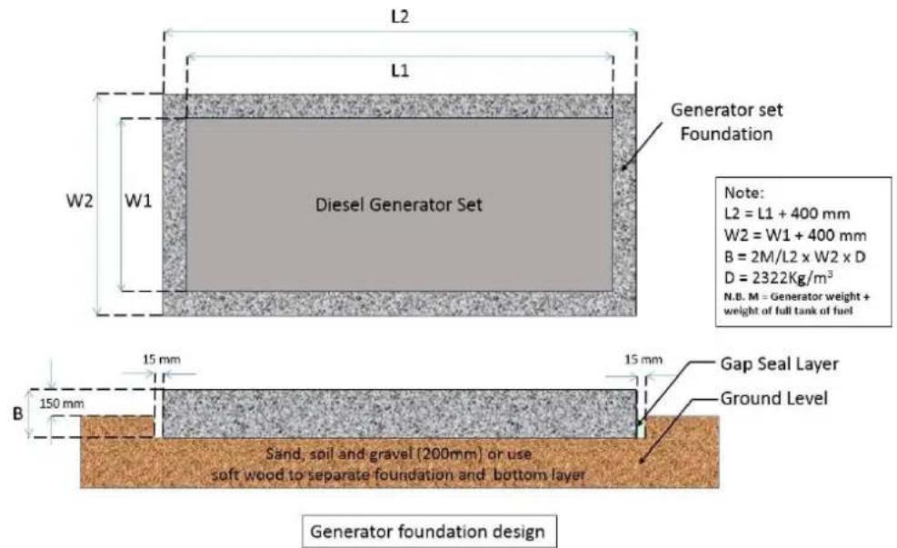
Calculation example - This is for guidance only for exact calculation you must use a Structural Engineer
DHY9KSEm weight (including fuel) = 688kg = M
L2 = 1.9m, W2 = 1.16m, D = 2322kg (density of concrete)
PD = Plinth depth in metres.
$$ \mathrm{PD} = \left(\frac {2 M}{L 2 x W 2 X D}\right) = \left(\frac {2 x 6 8 8}{1 . 9 x 1 . 1 6 x 2 3 2 2}\right) = \left(\frac {1 3 7 9}{5 1 1 7 . 7}\right) = 0. 2 6 9 m o r 2 6 9 m m $$
5.4. Design for Generator Set Working Room.
5.4.1. The complete installaon of generator set shall be designed to conform to all applicable building and any other applicable regulaons, so that it also meets the demands of operaon and planned maintenance.
5.4.2. You must make sure that diesel engine generator set working room is rainproof and windproof.
5.4.3. You must make sure that diesel engine generator set working room has adequate venlaon and suitable exhaust system, at the same me use pipes to exhaust the hot air generated from the radiator and prevent the hot air from returning.
5.4.4. You must make sure that you reduce harmful emission to environment.
5.4.5. The silencer and exhaust pipe shall be supported by the roof, the support method shall allow the exhaust pipe to expand.
5.4.6. It is not permied to install the exhaust system directly on the generator set.
5.4.7. Enough space shall be reserved for the diesel generator set for convenience of cooling, operaon and maintenance etc.
5.4.8. The generator space shall remain free of all materials not required for generator. The free space around and above the generator will be 1.5 metres and 2 metres above.
5.4.9. The generator set room must have a suitable, available re exnguisher which must which must conform to the specied standard.
5.4.10. Emergency lighng facilities shall be installed in the generator set working room for the convenience of operaon and maintenance.
5.4.11. No combustible and explosive materials are allowed to be placed in the generator set room.
5.5. Installaon of the Generator Set.

NOTE
Canopied generator sets are weather-proof but not water-proofed. Ideally they should be housed in a structure which must be suitable to protect the generator set from the worst of the weather. The structure must have adequate venlaon, and a correctly installed exhaust system and at least 1.5 metre clearance around the generator set to allow for maintenance and servicing purposes.
5.5.1. Decide on the posion of generator set
5.5.2. Use the secon 5.3. Design for the foundaon to correctly for correct foundaon installaon.
N.B. This is for guidance only for exact calculation you must use a Structural Engineer.
5.5.3. Use expansion bolts to ghtly x the generator set to the concrete foundaon through the installaon holes on the base frame.
5.5.4. Vibraon reducon units have been installed on our generator sets.
5.6. Venlaon.
5.6.1. When a generator set has been installed in its nal locaon, provision must be made to discharge the hot air to outside and allow cold air to enter from the outside, and avoid the hot air returning into the room.
5.6.2. The diagram below shows example of venlaon air ow. The purpose of this arrangement is to get cold air from the lowest point as much as possible, and allow heat/hot air from the engine and generator to be vented and cold air drawn in.

5.7. Exhaust.

NOTE
When more than one generator set is installed, you must make sure each machine has separate exhaust.
Serious damage will occur if rain or condensed water is allowed to enter the exhaust system. One water discharge opening shall be installed in the long exhaust pipe and posioned close to the generator set.
If the end of the exhaust pipe is above the height of the building then lightning protecon will be required and bonded to the ground.
5.7.1. Our standard conguraon diesel generator sets can be provided with accessories such as heavy duty silencer, so corrugated pipe and elbow etc. 5.7.2. Users can design the exhaust system of generator set working room by themselves.
5.7.3. When designing and installing the exhaust system, please consider the following aspects:
5.7.3.1. Ensure the total exhaust back pressure no higher than the maximum allowed value specied by the engine (usually generator set's maximum exhaust back pressure is no more than 5Kpa).
5.7.3.2. Fix the exhaust system to make sure the exhaust manifold and turbocharger are not subject to the vercal pressure and side stress.
5.7.3.3. Allow for hot shrinkage and cold expansion.
5.7.3.4. Allow enough space for generator set vibraon.
5.7.3.5. Reduce exhaust noise level.
5.7.3.6. Overload of exhaust backpressure will cause following adverse eect:
5.7.3.6.1. Loss of output power.
5.7.3.6.2. Reduced fuel eciency.
5.7.3.6.3. A rise in exhaust gas temperature.
5.7.4. In the exhaust system, so corrugated pipe shall be used to connect the exhaust pipe with the turbocharger, this pipe has three funcons as follows:
5.7.4.1. Separate the diesel engine with vibraon and the weight of exhaust pipe.
5.7.4.2. Compensate the heat expansion of exhaust pipe.
5.7.4.3. If the diesel generator set is installed on the an-vibraon base frame, the corrugated pipe will compensate for side-ways movement whilst engine is starng or stopping.
5.7.5. Noise reducon
5.7.5.1. When diesel generator set is running, normally it will generate noise level of equal to or below 96dB. Note the larger the load, the higher the noise level.
5.7.5.2. In order to meet the noise level standards established by the local environment regulaons and to prevent the noise polluon, which will aect people's normal life. It is then very important to further reduce the noise level of diesel generator by having it inside a suitable room.
5.7.5.3. When planning noise reducon you must fully consider the boom limit of air inlet/outlet volume needed by engine's normal running and the maximum allowed value for exhaust backpressure etc. Otherwise, the noise reducon method can seriously aect generator set's output power, it will make generator the set's temperature rise, and cause frequent malfuncon of the generator set, and can even shorten the generators life expectancy.
5.8. Cooling system.
NOTE
You should NOT allow the radiator to become blocked with debris, it will greatly act radiator's cooling capacity. It is therefore necessary to ush and clean the radiator at regular intervals.
5.8.1. Our standard congured diesel generator sets are ed with closed cycling water chilling units with fan and radiator installed.
5.8.2. Closed water chilling engine drive the cooling pump to generate coolant circulaon, which keeps the an-freeze in a connuous ow through the cylinder body which in turn will reduce heat.
5.8.3. The engine's cooling pump, radiator (or heat exchanger) forms a closed loop, pressure cycling and cooling system.
5.8.4. The most common cooling system is the cooling fan mounted directly in front of the radiator, which is driven by the engine This can be replaced by a heat exchanger, remote radiator or remote cooling tower etc.
5.8.5. If the installaon posion of the remote cooling fan is higher, then a transmission radiator is needed to prevent damage to the heat exchanger which can be caused by internal pressure being too high.
5.9. Coolant.
5.9.1. Cooling system must use a coolant which can protect the engine from contamination and freezing.
5.9.2. Coolant must be a mixture of pure water and an-freeze or pure water and an-rust uid.
5.9.3. In this mixture, the water PH value shall be between 6\~8, which usually suggest to use dislied water.
5.9.4. The specific mixing rao shall be according to local weather, and that of the coolant recommended by the engine supplier, and reference to the operaon (preparaon) manual of the coolant. Mix the liquids in separate containers evenly and then add the mixture into the radiator, make sure that the an-freeze will not freeze under low temperature.
5.9.5. In the areas where there is no possibility of freezing, the coolant can be a mixture of water and an-rust, according to the an-rust which recommended by the engine supplier and refer to its operaon manual, mix the liquids in a separate container evenly and then add the mixture into the radiator.
5.9.6. The rst me an-rust is added, you should keep the generator running until it gets hot enough to achieve the best an-corrosion aects.
5.9.7. Engine coolant has three funcons;
5.9.7.1. Provide enough heat transmission.
5.9.7.2. Prevent all metal and sealing materials within the cooling system from corrosion.
5.9.7.3. Provide sucient an-freeze capacity.
5.10. Changing Coolant.

WARNING
Only use approved an-freeze and mixed to the correct rao.
Using poor quality products can shorten the life of the engine and may cause early degradaon of hose and seals. This will damage be outside of the warranty. Coolant should be 33% of the total volume of cooling liquid.
5.10.1. The eecveness of an-freeze and an-rust will decrease over me and will need to be changed periodically.
5.10.2. YOU MUST change it regularly and should be changed in every two years or 2000 hours.
5.10.3. The an-rust mixture should be changed at least once every year. And if a coolant liter is installed it should be changed in every 6 months (please refer to the engine operaon manual for the specific intervals of the changes required).
5.10.4. When it is me to change the coolant, make sure the generator set has been shut down and the engine has been allowed to fully cool down, then open the radiator cap then open the radiator drain valve.
5.10.5. If the generator set is ed with a coolant iter, it should be changed at the same me.
5.11. Cleaning of the cooling system.

NOTE
If the cooling system is cleaned periodically, you need only to rinse with small amount of addives or clean water.
The air discharge valve in the engine body shall be located in the top point of the water path or near the thermostat, water temperature sensor, or you can loosen the water temperature sensor and re-ghten it when you see coolant run out of it so that it shows all air has been discharged.
5.11.1. When it is me to change the coolant, the radiator and cooling system will require cleaning, the suggested cleaning procedures are as follows:
5.11.1.1. Empty the cooling system.
5.11.1.2. Use clean water to rinse cooling system.
5.11.1.3. Mix 15% to 20% of condensed coolant to the cooling system, then run the generator set for once or twice (depending on amount of contaminaon) then discharge the coolant.
5.11.1.4. Once empty the cooling system can be re-llled with the normal mixture to rinse.
5.11.1.5. If contaminaon sll exists, then repeat the cleaning procedure until all contaminaon is cleared from the system.
5.11.1.6. Before adding coolant to the coolant system, please make sure the radiator's discharge valve and the engine's discharge valve are ghtly closed.
5.11.1.7. Add the coolant to the system to avoid air lock being formed in the system.
5.11.1.8. Air shall be discharged through the adding hole or the discharge valve in the engine body.
5.11.1.9. If a cooling system pre-heater is ed, the control valve for the heater should be opened. To make sure the system is fully vented when adding the coolant.
5.11.1.10. Aer the system has been fully cleaned and rinsed, add fresh coolant which has been mixed according to specied proporons, 33% anfreeze. Fill to 50mm from the top of the lling point. Run the engine and preheater (if ed) recheck level and top up as required.
5.12. Oil Lubricaon system.

NOTE
It is important to use quality lubricant oil with proper viscosity and which conform to the engine's specicaon.
We recommend that a high quality mul grade SAE 15W40 high service engine oil in diesel engine is used.
Periodically change the lubrication oil and oiliter so that the generator set maintains normal working.
Any malfuncons caused by wrong type of lubricang oil with low quality or long me periods between oil and oil liter change will be outside the scope of warranty.
5.12.1. Lubrican system is comprised of oil pan, oil pump, strainer, oil pipe, oil cooling unit, oil liter unit, and all the moving parts of the engine
5.12.2. The main purpose of the lubrication system is to provide sustained tempered oil lm between all moving parts to reduce fricon and wear, and to draw heat away from those moving parts.
5.12.3. Coat mechanical parts to improve sealing eect and prevenon of rust on surfaces.
5.12.4. Check the maintenance schedule to determine the oil change periods.
5.12.5. The rst oil change is normally done within 100 hours from when the generator set rst started.
5.13. Fuel System.
5.13.1. The fuel oil specicaon for a specific engine can be found by referring to the manufacturers' data sheets.
5.13.2. The generator set requires fresh diesel fuel without air and water and with proper pressure, of which all kinds of parameters such as sulphur content etc. shall meet naonal standards, and end use temperature grade to meet the requirement of customer's working environment.
5.13.3. Generally generator set's fuel system includes two parts, that is, engine's fuel system and an external fuel system.
5.13.4. We are only responsible for the engines fuel system which includes fuel tank and connecng fuel pipes etc.
5.14. Fuel Tank.
5.14.1. Our generator sets have a base frame type of fuel tank.
5.14.2. The fuel tank comes complete with fuel pipes and fuel level indicator.
5.14.3. The fuel supply system does not require the customer to make any additions.
5.14.4. Customers only need to add fuel to the base frame.
5.14.5. Users who intend to self-manufacture the fuel tank should use stainless steel or steel plate to make the backup tank, It should not be internally painted or galvanised.
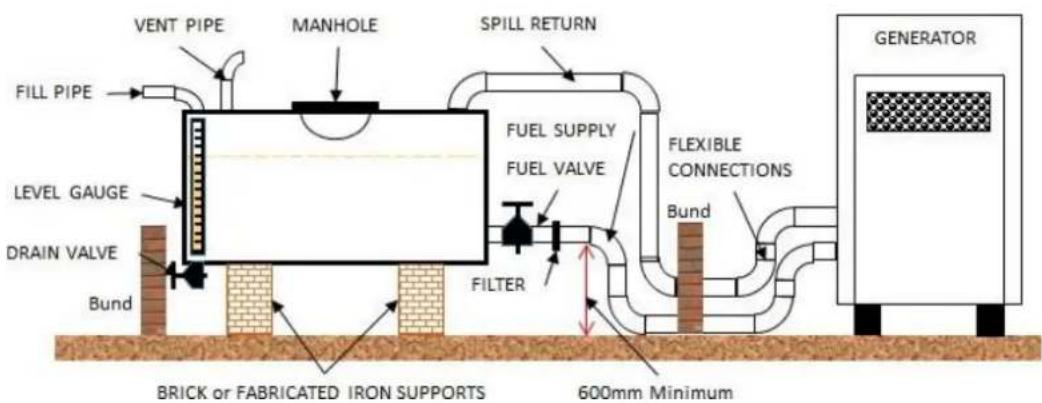
5.14.6. In addition, the conguraon of fuel tank assembly shall be as follows;
5.14.6.1. Air venlaon pipe above fuel tank surface.
5.14.6.2. Manhole on the top surface of fuel tank.
5.14.6.3. Fuel level indicator.
5.14.6.4. A discharge valve at the boom of fuel tank.
5.14.6.5. Earthing cables between fuel adding hole and fuel tank.
5.14.6.6. Separate panel with holes between fuel supply area and fuel return area, so that to reduce heat exchange.
5.14.6.7. The end of fuel supply pipe shall be 50mm above the boom of base frame to avoid deposits and water at the boom of fuel tank being sucked into fuel supply pipe.
5.14.6.8. The fuel level shall be higher than the fuel injector, to avoid fuel return from fuel injector, which can cause starng issues.
5.15. Installaon of the Fuel tank.
5.15.1. The posion of the fuel tank should ensure the maximum sucon fuel head is no less than 2 meters.
5.15.2. Sucon fuel head of the fuel transfer pump shall be calculated from the boom of the fuel tank.
5.15.3. The posion of the fuel tank shall ensure maximum return fuel head no less than 1.5 meters.
5.15.4. Return fuel head shall be calculated from the top of the base frame.
5.15.5. The arrangement of the fuel pipe shall avoid the fuel being aected from the heat eliminaon from generator set too much.
5.15.6. The maximum temperature of the fuel before fuel pump shall be lower than 60 degree Celsius.
5.15.7. There should be no fuel leaks in fuel inlet and fuel return pipe.
5.15.8. Flexible hoses need to be used to connect generator set with fuel transfer pipe, to prevent the eects of vibraon.
5.15.9. When engine's fuel inlet pipe is above 6 meters and below 10 meters, the inside diameter of the fuel inlet pipe must be at least 20% bigger than that of the hose installed in this engine. The fuel return pipe must be connected to the top of fuel tank. Do not connect directly to fuel inlet pipe.
5.15.9.1.1. Typical Layout – DO NOT use for design purposes.
5.16. Fuel SYSTEM.

WARNING
When adding fuel to the fuel tank, you must make sure the generator set has been stopped. You will need to prime the diesel pump before aempng to start the machine.
Allow the fuel to sele before the generator set is re-started. This will avoid any debris/foreign materials geng sucked into the diesel fuel supply hose, which will cause blockages in the fuel liter and failure to supply engine with sucient fuel, which in turn will decrease the output power.
Any malfuncon caused by bad quality of fuel is not in the scope of the warranty.
5.16.1. The content of the diesel fuel plays a very crical role in diesel engine's performance, life expectancy and the content of discharged material.
5.16.2. In order to achieve the rated power, fuel economy and specied emission standard, only use the fuel which is referred to in internaonal standard or naonal standard.
5.16.3. The parameters of diesel fuel include low temperature feature, sulphur content, specific gravity, water content and foreign material content shall be the rst priority when user need to choose the quality of the fuel.
5.16.4. Poor quality fuel will directly aect diesel generator set's start, lubrication, output power, discharge, and fuel liter change cycle etc.
5.16.5. Specific requirement for fuel please refer to engine operaon manual which aached with the generator set.
5.17. Control system.
5.17.1. Our diesel generator sets come with a control panel.
5.17.2. All of the control panels have digital meter at the core of control system.
5.17.3. Digital control panel;
5.17.3.1. The generator set can be controlled locally, and can also be started or stopped by remote control (controlled by an external signal line) users are required to correctly connect the signal line to this control panel. See the conncon details in the control panel operaon manual.
5.17.4. Automac transfer panel (oponal);
5.17.4.1. The automac transfer switch is used for transferring the load between generator set and mains, for details refer to control panel operaon manual.
5.18. Baery.

WARNING
You must make sure that the connecons for both positive and negative poles is correct. Incorrect connecons will cause malfuncon. It will cause damage to the charging alternator When generator set is running, baery cables are not to be disconnected.
5.18.1. The generator set standard conguraon provides a maintenance free starng baery.
5.18.2. You only need to connect the cables for the baery.
5.18.3. Our diesel generator sets' baery cables have been connected to the engines before shipment.
5.18.4. Maintaining the charge of the starng baery will determine how well the diesel engine generator set can start in a specied period.
5.18.5. The baery is connuously charged whilst the engine is running. generator.
5.19. Electrical connecons.

WARNING
All electrical conncons should be in compliance with BS7671 Requirements for Electrical Installaons, and other local regulaons.
5.19.1. Only fully qualified and experienced electrical technicians should carry out electrical installaon, service and repair work.
5.19.2. Cabling.
5.19.2.1. Due to movement of generang sets on their vibration mounts, all of the electrical conncon to the set should be made with exible cable.
5.19.2.2. The cable must be suitable for the output voltage, current and of the generang set.
5.19.2.3. In determining the size, allowances should be made for ambient temperature, method of installaon, proximity of other cables, volt drop, etc.
5.19.2.3.1. Cable volt drop.
5.19.2.3.1.1. Volt drop is dened as the amount of voltage loss that occurs through all or part of a circuit due to impedance.
5.19.2.3.1.2. The distance between the generator and the load should be given careful consideraon to keep the volt drop to a minimum.
5.19.2.3.1.3. The voltage drop across a cable can be found by checking in BS7671 Requirements for Electrical Installaons.
5.19.2.4. Before powering up the generang set you MUST carefully check all connexons for correct polarity, phasing, earthing and ghtness.
5.19.2.5. Current carrying capacity of the cables can be found in BS7671 Requirements for Electrical Installaons.
5.19.3. Ground/Earthing Requirements.
5.19.3.1. The frame of the generang set must be connected to a ground/earth electrode/spike.
5.19.3.2. Since the set is mounted on vibraon isolators, the ground/earth connecon must be exible to avoid possible breakage due to vibraon.
5.19.3.3. Ground/earth connecon cables or straps should have at least full load current carrying capacity and meet the current with BS7671 Requirements for Electrical Installaons, and all other applicable local regulaons.
5.19.4. Tesng of ground/earthing arrangements.

WARNING
Before inserng an earth electrode it is IMPORTANT that you check what is below the surface i.e. buried pipes, cables etc. YOU SHOULD NOT ASSUME that by just pushing earth electrode into the earth it will give a safe, suitable and sucient earthing point.
It should be tested in accordance with BS7671 Requirements for Electrical Installaons 612.7 Earth electrode resistance, "Where the earthing system incorporates an earth electrode as part of the installaon, the electrode resistance to Earth shall be measured".
5.19.4.1. Earth electrode method.
5.19.4.1.1. To carry out this test refer to BS7671:2008 On-Site guide.
5.19.4.2. Earth fault loop impedance tesng method.
5.19.4.2.1. To carry out this test refer to BS7671:2008 On-Site guide.
N.B. The expected reading for both methods in a TT system should be <200 .
5.19.5. Insulaon resistance tesng. All of our 1500RPM machines are fully tested during PDI.
5.19.5.1. Before starng the generang set aer installaon, test the insulaon resistance of the windings.
5.19.5.2. The Automac Voltage Regulator (AVR) should be disconnected and the rotang diodes either shorted out with temporary links or disconnected.
5.19.5.3. Any control wiring must also be disconnected.
5.19.5.4. A 500 V megger or similar instrument should be used.
5.19.5.5. Disconnect any earthing conductor connected between neutral and earth and megger an output terminal to earth.
5.19.5.6. The insulaon resistance should be > 1MΩ to earth.
5.19.5.7. Should the insulaon resistance be less <1M winding must be dried out.
5.20. Power distribuon system.

WARNING
All of our diesel engine generator sets must connect generator sets and base frames to the ground, please refer to the ground label for conncon point.
5.20.1. Our diesel engine generator set use three phase ve line system for power distribuon. The Neutral and Earth linked.
5.20.2. That is, three phase live wires, one neutral line and one ground line.
5.20.3. Users can choose three phase four lines for power distribuon.
6. OPERATION.

WARNING
To maximise the life expectancy of the generator set the user must maintain and operate the generator set in accordance with all instrucons.
6.1. Inspecon before use.
6.1.1. Once installaon is completed, our diesel engine generator set can be put into use. Each me before starng the generator set, following items shall be checked without fail;
6.1.1.1. Check that there is no dirt, dust or debris on the surface of generator set or engine. Check that the ambient temperature is within operational limits.
6.1.1.2. Check that the air inlet and venlaon path in the generator set working room is clear of any obstrucons.
6.1.1.3. Check fuel tank has sucient fuel for expected duraon of use.
6.1.1.4. Check the coolant and an-freeze level is normal.
6.1.1.5. Check that the air liter/s are in good condition.
6.1.1.6. Check that the fuel liter/s are in good condition.
6.1.1.7. Check If the lubricant level is within the specied range. Check that
6.1.1.8. the fuel valve is open and that the fuel pump has been primed.
6.1.1.9. Check baery cables are correct polarity and are secure.
6.1.1.10. Check the load is safe to be connected.
6.1.1.11. When the generator set directly connected to the load, you MUST make sure that the circuit breaker/s are OFF before starng.
6.2. Pre-heater (Opon).
6.2.1. For generator sets which have a pre-heater system installed the operator needs to decide if pre-heang is required before starting the generator set according to environment temperature.
6.2.2. The installed control panel can signal the engine to start the pre-heater if pre-heang is required.
6.3. Connecng to power.
6.3.1. Make sure that the circuit breakers on the control panel are ON, watch the panel until the background light turn on. This means the control panel has been connected to the power. At the same me make sure the fuel pipes are open, and the speed governor or the control unit in the electronic fuel injection generator set is working condition.
6.4. Starng.
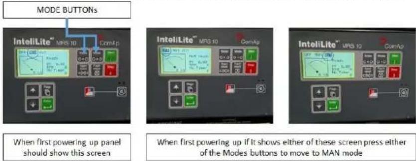
6.4.1. Turn the key switch to ON posion the panel will illuminate. Make sure the control panel is in MAN mode then control panel press the 'start' buon aer a couple of seconds the machine will commence its start up roune.
6.5. Remote starng.
6.5.1. For the control panels which are installed with remote self-start (or communicaon) instrument, the generator set pre-heang, start-up period and starng mes have are controlled by the program. Programme parameters can be set and modified by user, but it is strongly advised that before changing any parameter, assistance is sought from our aer sales team.

WARNING
Any starng method not done via the control panel will invalidate the warranty.
6.6. Running.
6.6.1. When the generator set begins to run at full speed, and the output voltage and frequency becomes normal and stable, operators can put the generator set into normal running condition and apply loads.
6.6.2. During the generator set's running period, the operator/s MUST check at regular intervals for the following;
6.6.2.1. is the generator set is running normally,
6.6.2.2. is the control panel instrument is indicang the right posion,
6.6.2.3. does the control panel have any pre-warning indicaon,
6.6.2.4. the fuel level in the base frame.
6.7. Emergency stop.
6.7.1. In case the generator set was found to have any severe malfuncon or power distribuon malfuncon. You MUST operate the emergency stop buon on the control panel. This will immediately shut down the generator set.

WARNING
DO NOT operate the emergency stop buon under normal conditions.
6.8. Normal stopping procedure.
6.8.1. Before stopping the generator set under normal operang condions, rst disconnect all loads from the generator by turning o all load, then turn o all of the circuit breakers.
6.8.2. Press the stop buon - Once only. Once the stop buon has been pressed the machine will carry out a controlled shutdown process.
6.8.4. Some generator sets are ed with a stop solenoid, it is therefore not possible to stop the generator set by turning o the key switch on the control panel.

NOTE
If the key switch is turned o and turned back on the machine will come to a stop. This stopping is caused by a fault and NOT to be used as the stopping method
6.9. Checks aer running.
6.9.1. Aer the generator set stop running, it will be necessary to carry on following checks;
6.9.1.1. Check if the generator set for
6.9.1.1.1. Oil lubricant leaks,
6.9.1.1.2. Fuel leaks,
6.9.1.1.3. Coolant (an-freeze) leaks.
6.9.1.2. Shut down fuel valve
6.9.1.3. When necessary shut down air inlet and air exhaust vents in the generator set's working room area.
6.9.2. Turn o the power key switch on the control panel, remove the key and keep it in a safe place and in good condition.
6.9.3. When the generator set need to be shut down for a long me or is under maintenance, please dis-connect the start baery's negave cable, and fully discharge the fuel and an-freeze liquid when necessary.
6.9.4. For the self-start (remote start) generator sets, some of the above items are not applicable.
6.9.5. Aer the self-start (remote start) generator set stops, please keep it in the same status as that of pre-start (ready to start), so that it be can started at any me under emergency cases.
6.10. Run record.
6.10.1. The user shall record each running operaon.
6.10.2. The run record has various forms.
6.10.2.1. The basic content shall cover:
6.10.2.1.1. Time run for current period,
6.10.2.1.2. Accumulated running me for this generator set,
6.10.2.1.3. Value of engine's;
6.10.2.1.3.1. Oil pressure gauge.
6.10.2.1.3.2. Temperature meter.
6.10.2.1.3.3. Output voltage.
6.10.2.1.3.4. Frequency.
6.10.2.1.3.5. Maximum power(current) etc.
6.10.2.1.3.6. The running conditions/situaon.
6.10.2.1.3.7. Any malfuncon warning or generator set shut downs.
6.10.3. Only when the correct and complete record for running (maintenance) have been kept can the user can get correct and proper aer sales (warranty) service.
6.11. Warnings for mis-use.
| WARNING | DO NOT allow the generator set to run with overload for long periods, otherwise malfuncon will occur, this will decrease the generator set's life expectancy. |
| WARNING | It is forbidden to remove or change any of the generator set components when it is running. |
| WARNING | Any coolant which is going to be added needs to be of the same specicaon as that of the original cooling system. When opening the radiator cover. You MUST pay aenon to the possible coolant high temperature to avoid the steam burns to the user or bystanders. |
| WARNING | When emptying high temperature lubricant oil, you MUST avoid being burnt. |
| WARNING | The fuel being used shall be conform to naonal standard, otherwise it will cause malfuncon of the engine's fuel pump or fuel injector. |
| WARNING | For engines ed with a turbo-charger, it is advisable NOT to add 50% or above instant load to the generator set. Otherwise this will cause the generator set to stall. |
| WARNING | For electrically large consumpon equipment, it is suggested that the users need to use methods such as voltage decrease and frequency change etc. to control the start, to reduce huge impact on the generator set when starng such loads. |
| WARNING | It is suggested that backup generators or generator sets which haven't been run for a long me shall be run up to working temperature at least once a month. This of generator set need to be connuously run with full load for 4 hours at least one me per year. |

WARNING
For generator sets which are connected in parallel and controlled by manually by operators must make sure they are running synchronously (same frequency, same phase-sequence, same phase, and same voltage) before switching on. All loads MUST be switched o before trying to stop the parallel generator groups. During the parallel generator group running, you MUST remain alert to individual generators stopping so as to avoid the parallel generator group stopping.
6.12. Control system operaon.
6.12.1. Generator control panel operaon
6.12.1.1. Our generator set standard supply two dierent control module: one is single generator with remote start funcon, the other is single generator with Automac Mains Failure panels (ATS).
6.12.2. Start-up generator
6.12.2.1. Turn OFF all loads and switch OFF all circuit breakers.
6.12.2.2. Turn the Generator set Main Circuit Breaker and other circuit breakers to the "OFF" posion.
6.12.2.3. Turn the baery isolator ON.

natural_image
Two-panel image showing a red-lipped switch on a black background, labeled 'OFF' and 'ON' (no text or symbols on the switches themselves)6.12.2.4. Make sure that the control panel power circuit breaker is turned ON.
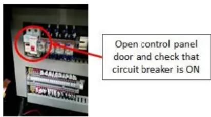
6.12.2.5. Press the start buon on the front of the control panel.
6.12.2.6. If generator set is ed with pre-heater (air intake or water pre-heater). The Pre-heat engine will illuminate on module LCD. Preheang me varies by coolant temperature. Usually water pre-heater completes in about 60 seconds, air intake pre-heater completes 10 seconds. Aer preheang the LCD puts out and the engine begins to start. It will aempt to start again about 5 seconds later if the engine fails to start.
6.12.2.7. Aer the engine starts successfully, allow the engine to warm up for about 5 minutes. If the engine does not re during the pre-set number of aempts to start (start aempts number: 3 mes), the Alarm LCD would ash. If you need to restart, wait at least 30 seconds before the retry.
6.12.2.8. Check the reading of voltage & frequency meter.
6.12.2.9. Once the generator set is running at the correct voltage, frequency and at operang temperature the main circuit breaker can be switched "ON".
6.12.2.10. Starng with heaviest loads first then lighter loads turn "ON" each load circuit breaker.
6.12.3. Control panel.

1 - Fuses
4 - Connecon terminals
7 - MRS10 control
2 - Panel circuit breaker
5 - Main key switch (rear)
3 - Control relays
6 - Emergency stop (rear)
6.12.4. Generang set control system
6.12.4.1. To control and monitor the generang set, an electronic control system has been used. The MRS10 control system is ed. The Control panel provides a means of starng and stopping the generang set, monitoring its operaon and output and automacally shung down the set in the event of crical conditions arising such as low oil pressure or high engine temperature.
6.12.4.2. This module is mainly used for auto/manual start-up protecve stop and manual/auto switchover the generator set power and mains power. It can also remote control/measure/monitor generator set through a computer. The MRS10 panel has an LCD screen to display the set parameters of the generator set, and has O/Manual/Auto/Measurement modes.
6.12.5. MRS10 Control panel push buons funcons and LED indicaons.
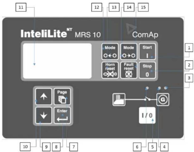
| 1 – Start-upStarts the engine. | 2 – StopStops the engine. | 3 – Generator set failureGenerator set failure: Red LED starts ashing when generator set failure occur. Aer fault reset buon is pressed, goes to steady light (if an alarm is sll acve) or is o (if no alarm is acve) |
| 4 – Generator set voltage presentGreen LED is on, if gen voltage is present and within limits | 5 – Generator set power on/o.Manual turn on/o the generator set power switch | 6 – Connect generator set power present.Green LED light, generator set output switch is on, otherwise the green LED ashes. |
| 7 – PageCyclic selecon of the display mode (measurement adjustment). | 8 – EnterConrm the set point value. | 9 – DOWNSelect the set point, select the screen or decrease set value point. |
| 10 – UPSelect the set point, select the screen or increase set value point. | 11 – DisplayDisplays funcons/informaoon. | 12 – Generator set voltage presentGreen LED is on, if gen voltage is present and within limits. |
| 13 – Horn resetDeacvates the horn. | 14 – Mode rightChange the generator set mode le-handed. (OFF-MAN-AUTO-MEASUREMENT) | 15 – ResetClear failure and alarm |
6.12.6. Checking parameter.
6.12.6.1. Press page push buon several mes to select MEASUREMENT menu
6.12.6.2. Use UP/DOWN pushbuon to check the detail.
6.12.7. Operaon & applicaon.
6.12.7.1. When the power supply LED is lit it means the controller is acve, the user can then select operaon type (OFF/MAN/AUTO/MEASUREMENT).
6.12.7.2. OFF mode.
6.12.7.2.1. Start; Stop; Mains power on/o; Generator set power on/o are inactive in this mode.
6.12.7.3. MAN mode.
6.12.7.3.1. Press the start push buon to start engine
6.12.7.3.2. When the output voltage is in the set range.
6.12.7.3.2.1. Press mains power on/o pushbuon to turn on the switch.
6.12.7.3.2.2. Press mains power on/o pushbuon, the switch will be turned on, otherwise there will be output voltage.
6.12.7.3.3. Press generator set power on/o pushbuon to turn on the switch.
6.12.7.3.4. Press mains power on/o pushbuon, the switch will be turned on, otherwise there will be no output voltage.
6.12.7.3.5. Press and hold the stop push buon unl engine comes to a complete stop.
6.12.7.4. AUTO Mode.
6.12.7.4.1. When mains power is conrmed.
6.12.7.4.1.1. The controller turns on the mains power switch.
6.12.7.4.1.2. The controller starts the engine aer emergency starng-up delay.
6.12.7.4.1.3. If the mains power comes back during the start-up period, the controller will turn o the mains power switch and stop engine aer switch delay.
6.12.7.4.2. When the engine speed is higher than the lowest set value in maximum delay, the controller will turn on the generator set power switch, otherwise the controller will go into alarm and stop engine.
6.12.7.4.3. Once the mains power is restored.
6.12.7.4.3.1. The controller will turn on the generator set power switch aer the mains power comeback delay.
6.12.7.4.3.2. The controller will turn on the mains power switch aer the generator set power delay has expired.
6.12.7.4.3.3. Cool-down and stop the engine.
6.12.7.5. Alarm condion.
6.12.7.5.1. The user can view the alarm list in the last display of the MEASUREMENT menu, Select MEASUREMENT menu by pressing UP buon, you will see all acve alarm number/s in the upper le secon of LCD display. All acve alarm/s are shaded and not conrmed.
6.12.7.5.2. Pressing the reset buon will conrm all alarms, all inacve alarms will be cancelled. If a new alarm occurs, this acve alarm will be displayed on the LCD display and is in an acve state shown on main measurement screen.
6.13. Automac Transfer Switch (ATS).
6.13.1. If the generator set is to be used for self-start standby power, and the customer requires a fully automac transfer between mains power and generator set power. To maintain all loads present the customers generator set will require the installaon of an ATS panel.
6.13.2. See ATS secon 10.
7. MAINTENANCE
7.1. General outline.
7.1.1. In order to obtain maximum operaon safety and life expectancy of the generator sets, periodic maintenance is very important. You MUST strictly observe the terms on generator set's maintenance which will maintain the generator set's performance and reduce its damage to environment.
7.1.2. You MUST correctly identify and strictly observe the labels (drawings, words and warnings etc.) on the diesel generator set and in manuals these can be of great help in correct maintenance and safe operaons.
7.1.3. Maintenance of the generator set MUST only be carried out when it has been stopped and the cable which connects to the negave pole of the baery has been dis-connected. This will make sure that the generator set will cannot be started by accident.
7.2. 1500rpm diesel generator engine maintenance program.
7.2.1. Inial commissioning to include (engine only - excludes electrical connexons), esmated me: 2 hours. Parts required: oil and coolant as required.
7.2.1.1. Check and II engine with oil.
7.2.1.2. Check and II diesel pump to correct oil level. Check and II coolant system.
7.2.1.3.Add sucient diesel - minimum required amount shall be no less than 75% for the rst ll and thereaer 25%.
7.2.1.4. Load test at rated load if possible (this is done before dispatch so may not be required). Test ATS if required.
7.2.1.5. Check all outputs, voltages, frequency, 12 volt charging, ATS charging etc. Check and adjust 12 volt alternator belts.
7.2.1.6. Check wiring loom and hoses for correct alignment. Check baery condion.
7.2.1.7. Check coolant mixture and level. (33% an-freeze)
7.2.1.8. Check for uid leaks.
7.2.1.9. Check control panel funcons and demonstrate to customer if required. General all round inspecon.
7.2.2. Every 250 hours or 6 months (whichever is sooner), esmated me: 3 hours, parts - oil Iters, diesel Iters, air Iter.
7.2.2.1. As above 6.2.1. plus:
7.2.2.2. Full service to include engine oil change.
7.2.2.3. Fuel pump oil change.
7.2.2.4. All engine oil Iters, diesel Iters and air Iter changed.
7.2.2.5. Load test at rated load if possible and run for 2 hours at 50%+ load. General all round inspecon - advice any potential issues.
7.2.3. Every 1000 hours, esmated me: 4 hours, parts - oil lters, diesel lters, air lter.
7.2.3.1. As above 6.2.1./6.2.2. plus,
7.2.3.2. Adjust valve clearances.
7.2.4. Every 2 years or 2000 hours.
7.2.4.1. Replace coolant mixture. Replace fan belts.
7.2.4.2. Check and replace any rubber hoses if required.
7.2.4.3. If the generator is being run under a very light load for most of the me, it may require load tesng on a more frequent basis. IMPORTANT see secon 2.4. Under loading of Diesel Generators.
7.3. Alternator.
7.3.1. Periodically clean the inside and outside of the alternator, the frequency of cleaning depends on the generator set's ambient environment.
7.3.2. When the cleaning becomes necessary, following procedures can be followed;
7.3.2.1. Isolate the baery to prevent accidental starng, remove all other sources of power.
7.3.2.2. Wipe o the dirt, contaminant, oil stain, water or any other liquid from the surface.
7.3.2.3. Remove any dust, dirt and debris form the venlaon mesh grille.
7.3.2.4. Remove any dust, dirt and debris from the coils and conncons. Dust, dirt and debris can cause the coils to overheat or damage the insulaon.
7.3.2.5. All dust, dirt and debris contaminaon needs to be collected by dust collector. DO NOT use air blowers or high pressure water spray to clean the alternator. The use of liquids inside the alternator will increase the humidity inside the alternator and will decrease the insulaon resistance. If there is excessive humidity inside the alternator it must be correctly dried to raise the insulaon resistance to an acceptable limit. Ideally the
insulaon resistance would be innity, however a resistance value of greater than 2 MΩ would be acceptable anything lower would require further invesgaon.
7.4. Control panel.
7.4.1. Daily maintenance for the control panel should be carried out to make sure that the external surface is clear of any dust, dirt or debris. Make sure that all of the indicators are clear and easy to read, and that the operaon buons give a reliable exible.
7.4.2. When the generator set is running, vibraon will cause parts to become loose, you must periodically check the instruments of the control panel and parts and cable's connecons are secure.
7.4.3. It is NOT recommend that the user aempts to repair the control panel. It is advised that if the control panel fails to funcon correctly you contact your dealer.
7.5. Baery.
7.5.1. The generator set is ed with a sealed lead acid baery/ies.
7.5.2. Baeries which have been stored for a long me should be properly charged before being used.
7.5.3. Baeries with low voltage will not be able to start the generator correctly.
7.5.4. In extreme cold conditions the baery will not be able to deliver its full potential. If you need to start the generator in cold weather it is advisable to remove the baery and move to a warm area and allow the baery to warm up naturally to ambient temperature ideally above 10^ C.
| GENERATOR START/STOP TIME | TIME | |||||||
| ACCUMULATED RUNNING TIME | ||||||||
| OIL PRESSURE | ENGINE PARAMETER | |||||||
| TEMPERATURE | ||||||||
| VOLTAGE | ||||||||
| CURRENT | GENERATOR PARAMETER | |||||||
| FREQUENCY | ||||||||
| POWER | ||||||||
| MALFUNCTION | ||||||||
| OPERATOR | ||||||||
| REMARK |
7.6. Generator set running record.
7.7. Maintenance record.
| Maintenance record. | ||||
| Maintenance me :- | Serial Number :- | |||
| Generator set model :- | Engine model :- | Alternator model :- | ||
| Generator set serial number :- | Engine serial number :- | Alternator serial number :- | ||
| Accumulated running hours :- | Maintenance cycle :- | |||
| Reason/s for maintenance :- | ||||
| Periodic maintenance :- | Breakdown :- | |||
| Inspecon and repair :- | ||||
| Inspecon and adjustment :- | ||||
| Change of parts :- | ||||
| Clean and maintenance :- | ||||
| Other :- | ||||
| Conclusion notes :- | ||||

other
The image contains an electrical schematic diagram for a three-phase motor (DSE 3110). It includes: - Power Supply: A schematic of the motor's internal circuit with labeled pins (e.g., PE, D.S2, S1, S2, T1, T2, T3, T4, T5, T6, T7, T8, T9, T10, T11, T12, T13, T14, T15, T16, T17, T18, T19, T20, T21, T22, T23, T24, T25, T26, T27, T28, T29, T30, T31, T32, T33, T34, T35, T36, T37, T38, T39, T40, T41, T42, T43, T44, T45, T46, T47, T48, T49, T50, T51, T52, T53, T54, T55, T56, T57, T58, T59, T60, T61, T62, T63, T64, T65, T66, T67, T68, T69, T70, T71, T72, T73, T74, T75, T76, T77, T78, T79, T80, T81, T82, T83, T84, T85, T86, T87, T88, T89, T90, T91, T92, T93, T94, T95, T96, T97, T98, T99), each connected to a terminal block (X-1 to X-9). The diagram includes labels for pin numbers (e.g., 1-12), phase voltages (e.g., 1V to 2V), and connection points (e.g., PE at 12V and -X3:1; GND at 1V and -X3:3). The diagram includes annotations such as 'Generator Voltage', 'Engine Ground', 'POWER PRODUCTS', and 'HYUNDAI POWER PRODUCTS'. The table on the right provides a scale and quantity table for the 'HYUNDAI POWER PRODUCTS' device.
9. USEFUL FORMULAE
| Direct current | Single phase2-wire | Two phase4-wire | Three phase4-wire | |
| To nd amps when HP is known | × 746Ex Eff | × 746Ex Eff × PF | × 7462 × Ex Eff × PF | × 7461.73 × Ex Eff × PF |
| To nd amps when kW is known | × 1000E | × 1000Ex PF | × 10002 × Ex PF | × 10001.73 × Ex PF |
| Amps when kVA is known | × 1000E | × 10002 × E | × 10001.73 × E | |
| Kilowas - kW | (I × E)1000 | (I × E × PF)1000 | (I × 2 × Ex PF)1000 | (I × 1.73 × Ex PF)1000 |
| kVA | (I × E)1000 | (I × Ex × 2)1000 | (I × Ex × 1.73)1000 | |
| Horse Power - HP | × E × Eff746 | × E × Eff × FF746 | × Ex × 2 × Eff × PF746 | × Ex × 1.73 × Eff × PF746 |
| I = AMPS | E = LINE VOLTAGE | Eff = EFFICIENCY |
| kW = KILOWATTS | PF = POWER FACTOR | kVA = KILOVOLT AMPS |
| HP = HORSEPOWER | ||
NOTE :- Eciency varies between 86% (for 25kVA) to 93% (for 1000 kVA). Generally the larger the alternator, the greater its eciency. The power factor for normal purposes should be taken about 0.80.
| WEIGHTS OF LIQUIDS | |||
| Liquid type | Lb/Imperial gallon | Kg per litre | Specific gravity |
| Water | 10.00 | 1.00 | 1.000 |
| Lube oil | 9.00 | 0.90 | 0.916 |
| Diesel fuel | 8.50 | 0.85 | 0.855 |
| Kerosene | 8.00 | 0.80 | 0.800 |
10. ELECTRICAL INSTALLATIONS WITH OPTIONAL ATS EQUIPMENT
An Automac Transfer Switch (ATS) is an electrical device that can automacally switch a load between two sources. Some transfer switches are manual (MTS), in these installaons the operator manually transfers the load to a dierent source by means of a switch, while others are automac and switch to an alternate source of power when they sense one of the power sources has been lost. Typically the when the mains supply fails the standby power source (generator) is brought on-line and supplies your electrical system. Once the mains is restored the ATS wil transfer the load back to the mains and will do a med shutdown of the generator.
10.1. All electrical installaons should be carried out by a competent person as described in, and in accordance with;
10.1.1. BS7671:2008 – Requirements for Electrical Installaons
10.1.1.2. BS7671:2008 - On-Site Guide, incorporang Amendment No 1.
10.1.3. If in any doubt contact an Approved Electrician.
10.1.4. All drawings contained in this document are supplied for guidance only.
10.2. EARTHING ARRANGEMENTS
10.2.1. All of our single and three phase generators are supplied with a connected Neutral/Earth link.
10.2.2. Should the neutral/earth link be removed for any reason it, it is very important to note that with a oang earth generator the combinaon of equipment to be supplied shall not exceed the following;
10.2.2.1. Only one item of Class 1 equipment – i.e. not double insulated
10.2.2.2. One or more of Class 2 equipment – i.e. double insulated, as shown on symbol ☐
10.2.2.3. Or a combinaon of - Only one item of Class 1 equipment and one or more of Class 2 equipment.
10.2.3. Earthing cable should be sized in accordance with BS7671 – Requirements for Electrical Installaons, incorporating the latest Amendments. You MUST always check for latest version of regulaons.
10.2.4. Earth electrodes should be tested in accordance with earth electrode test Figure 10.3.5.2 in BS7671:2008 - On-Site Guide, incorporating Amendment No 1. You MUST always check for latest version of regulaons.
10.3. MANUAL CHANGEOVER
10.3.1. The next secon covers the Manual Changeover connecons for connecng the generator to a property with a normal mains connecon supplied by the Electricity Distributor.

WARNING
- UNDER NO circumstances should a stand-by generator be allowed to feed the Naonal Grid.
- UNDER NO circumstances should the installaon be allowed to back feed into a property. The pracce is extremely DANGEROUS and can result in serious injury.
10.3.2. Single phase Manual changeover switching. (Suppliers - Combined Neutral/Earth).

flowchart
graph TD
    A["Earth"] --> B["To Consumer Unit"]
    B --> C["From Generator"]
    C --> D["From Meter"]
    D --> E["Manual Changeover Switch Single Phase connections"]
    subgraph From_Generator
        F1["1"] --> G1["2"]
        F2["3"] --> G2["4"]
        F3["5"] --> G3["6"]
        F4["7"] --> G4["8"]
        F5["9"] --> G5["10"]
        F6["11"] --> G6["12"]
    end
    subgraph To_Consumer_Unit
        L1["L1"] --> M["N"]
        M --> N["Spare"]
    end
10.3.2.1. Wiring schemac. (Suppliers - Combined Neutral/Earth).
10.3.2.1.1. Single phase interconnecon.
10.3.2.1.1.1. Interconnecon wiring schemac. (Suppliers - Combined Neutral/Earth).
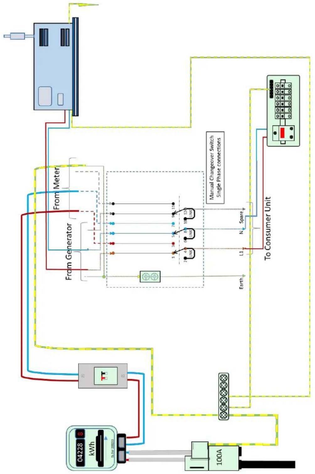
flowchart
graph TD
    A["04228 kWh"] --> B["100A"]
    B --> C["To Consumer Unit"]
    C --> D["Manual Changeover Switch Single Phase connections"]
    D --> E["From Meter"]
    D --> F["From Generator"]
    D --> G["Earth"]
    D --> H["Spare"]
    D --> I["N"]
    D --> J["L1"]
    D --> K["UNK"]
    D --> L["UNK"]
    D --> M["UNK"]
    D --> N["UNK"]
    D --> O["UNK"]
    D --> P["UNK"]
    D --> Q["UNK"]
    D --> R["UNK"]
    D --> S["UNK"]
    D --> T["UNK"]
    D --> U["UNK"]
    D --> V["UNK"]
    D --> W["UNK"]
    D --> X["UNK"]
    D --> Y["UNK"]
    D --> Z["UNK"]
    D --> AA["UNK"]
    D --> AB["UNK"]
    D --> AC["UNK"]
    D --> AD["UNK"]
    D --> AE["UNK"]
    D --> AF["UNK"]
    D --> AG["UNK"]
    D --> AH["UNK"]
    D --> AI["UNK"]
    D --> AJ["UNK"]
    D --> AK["UNK"]
    D --> AL["UNK"]
    D --> AM["UNK"]
    D --> AN["UNK"]
    D --> AO["UNK"]
    D --> AP["UNK"]
    D --> AQ["UNK"]
    D --> AR["UNK"]
    D --> AS["UNK"]
    D --> AT["UNK"]
    D --> AU["UNK"]
    D --> AV["UNK"]
    D --> AW["UNK"]
    D --> AX["UNK"]
    D --> AY["UNK"]
10.3.1.1.2. Single phase Wiring schemac. (Generator - Neutral/Earth ed).
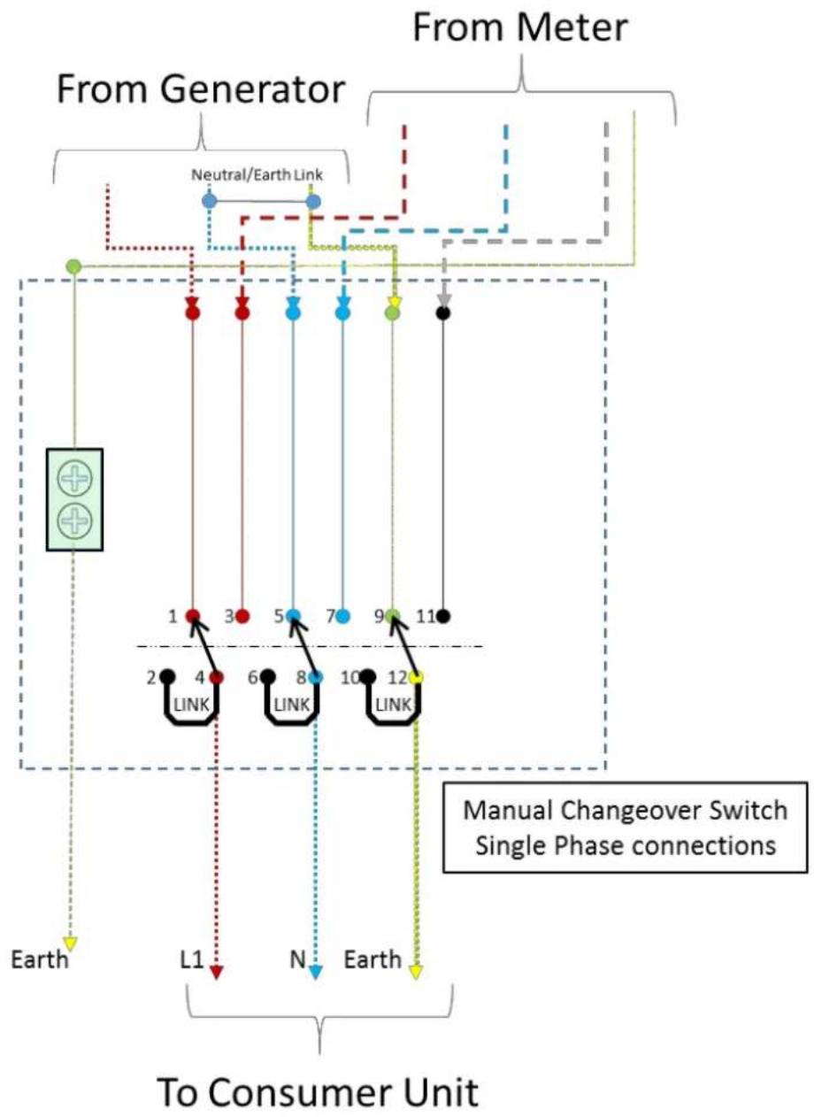
flowchart
graph TD
    A["From Generator"] --> B["Neutral/Earth Link"]
    B --> C["1"]
    B --> D["3"]
    B --> E["5"]
    B --> F["7"]
    B --> G["9"]
    B --> H["11"]
    I["To Consumer Unit"] --> J["2"]
    I --> K["4"]
    I --> L["6"]
    I --> M["8"]
    I --> N["10"]
    I --> O["12"]
    P["Manual Changeover Switch Single Phase connections"] --> Q["Link 1"]
    P --> R["Link 2"]
    P --> S["Link 3"]
    P --> T["Link 4"]
    P --> U["Link 5"]
    P --> V["Link 6"]
    P --> W["Link 7"]
    P --> X["Link 8"]
    P --> Y["Link 9"]
    P --> Z["Link 10"]
    P --> AA["Link 11"]
10.4.3. Three phase Manual changeover.
10.4.1.3. 1500 rpm machines – BLADES ATS. N.B. Cable colours are for indicaon purposes only.
Connection diagram for BLADES ATS Communication cable To suit DHY 1500 rpm machines – BLADES ATS

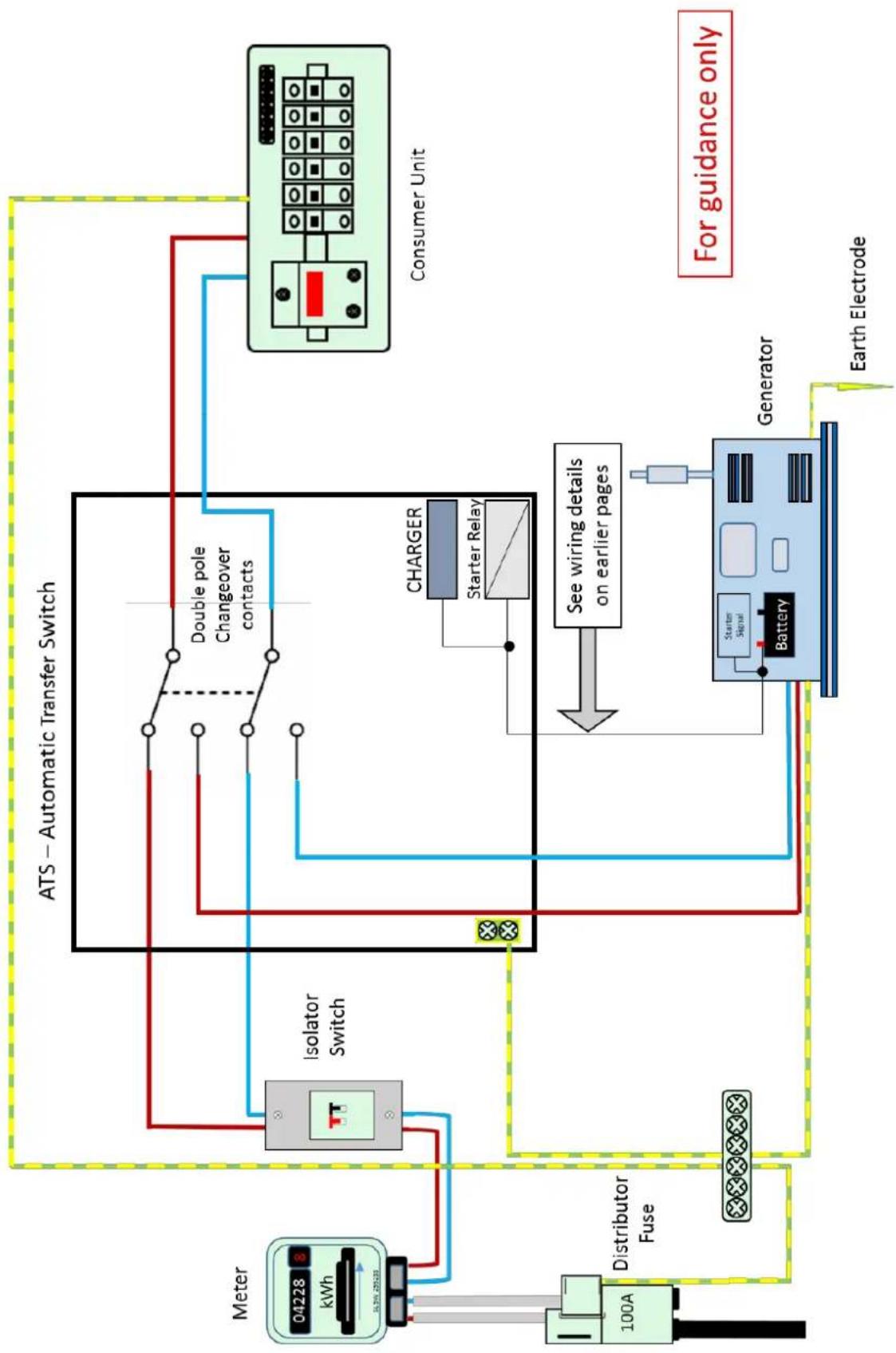
flowchart
graph TD
    A["04228 kWh"] --> B["100A"]
    B --> C["Distributor Fuse"]
    C --> D["Isolator Switch"]
    D --> E["ATS – Automatic Transfer Switch"]
    E --> F["Double pole Changeover contacts"]
    F --> G["CHARGER"]
    G --> H["Starter Relay"]
    H --> I["Consumer Unit"]
    I --> J["Generator"]
    J --> K["Battery"]
    K --> L["Earth Electrode"]
    style A fill:#f9f,stroke:#333
    style B fill:#ccf,stroke:#333
    style C fill:#cfc,stroke:#333
    style D fill:#fcc,stroke:#333
    style E fill:#cff,stroke:#333
    style F fill:#ffc,stroke:#333
    style G fill:#cfc,stroke:#333
    style H fill:#fcc,stroke:#333
    style I fill:#cfc,stroke:#333
    style J fill:#fcc,stroke:#333
    style K fill:#cfc,stroke:#333
    style L fill:#fcc,stroke:#333

flowchart
graph TD
    A["04228 kWh"] --> B["Distributor Fuse"]
    B --> C["Charger"]
    C --> D["Charger Relay"]
    D --> E["Four pole Changeover contacts"]
    E --> F["AtS – Automatic Transfer Switch"]
    F --> G["Earth Electrode"]
    G --> H["Generator"]
    H --> I["Battery"]
    I --> J["See wiring details on earlier pages"]
    J --> K["Charger"]
    K --> L["Starter Relay"]
    L --> M["Four pole Changeover contacts"]
    M --> N["AtS – Automatic Transfer Switch"]
    N --> O["Earth Electrode"]
    O --> P["For guidance only"]
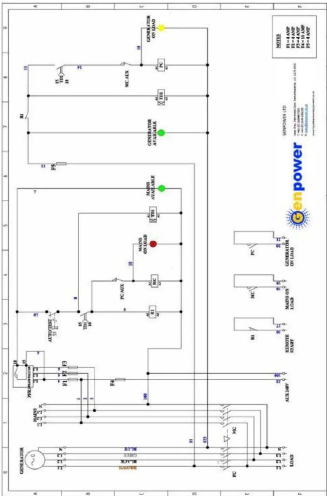
11.1. GSM/GPRS remote control - oponal.
11.1.1. Our 1500RPM range of generators can be remotely controlled by the use of Global System for Mobile Communications (GSM) & General Packet Radio Services (GPRS) technology.
11.1.2. The generator will be ed with all of the GSM equipment including GSM antenna/GPRS sim prior to delivery. Once you take delivery you will be given LOGIN details to hp://websupervisor.comap.cz/
11.1.3. Once you LOGIN via your PC/Smart phone/Tablet you will be able to do the following tasks;
11.1.3.1. Check the generator status.
11.1.3.2. Carry out remote START/STOP.
11.1.3.3. Monitor hours run, fuel, load, temperature, oil pressure etc.
11.1.4. The system can be set up to automacally send SMS text messages or email alerts for all alarms/events.
11.2. Ethernet remote control - oponal.
11.2.1 1. Open maintenance door where control panel is located to nd Ethernet port (Note: Due to machines varying in size, actual locaon may dier from image).

natural_image
Industrial machine with control panel and mechanical components (no visible text or symbols)11.2.1.2. Insert Ethernet cable, (Cat5e or higher is recommended), into faceplate and run cable down and out the holes in the base of the unit. We advise you to cable e it to appropriate locaons. You would also need to ensure the cable has relevant protecon from weather conditions once out of the unit.

natural_image
Interior view of an industrial control panel with digital display and warning labels (no readable text or symbols)11.2.1.3. Wire the cable into your property and plug into the back of your router. The light on the Ethernet cable should start ashing. (Providing the control panel is switched on at the generator)
11.2.1.4. Go back to the generator. Turn the key so the control panel turns on (If not already) and change seng to 'AUTO' by pressing the 'Mode' buon.
11.2.1.5. Go into the 'Comms Sengs' and change/ensure 'DHCP' is enabled. Also take note of the Controller Address'. Then, restart control panel.
11.2.1.6. Go back into 'Comms sengs' and ensure/change 'Airgate' seng to enabled, and restart control panel.
11.2.1.7. Upon restarng, while on the start screen, scroll using the up arrows unl you are viewing a screen which reads 'Airgate ID: xxxxxxxxxxxx'. Take note of this Airgate ID.
11.2.1.8. Leave generator on Auto mode and return to your property.
11.2.1.9. Using a PC/Laptop go to hp://websupervisor.comap.cz/
11.2.1.10. You must create a log in for Web Supervisor (WSV).
11.2.1.11. Once you receive this log in, log into WSV and click on 'Add new genset'
11.2.1.12. You will then be viewing the unit conguraon page as shown;

11.2.1.13. Enter a name for your unit, select me zone, input GPS coordinates (If required), and ensure you have 'Stac – No GPS' selected.
11.2.1.14. Change language if required.
11.2.1.15. Enter the 'Airgate ID' & 'Controller Address' as noted previously from the generator.
11.2.1.16. The Controller's default sengs are 'Controller Address = 1', 'Controller Password = 0', 'Access Code = 0'
11.2.1.17. Enter an email address for email alerts regarding faults/alarms to be sent to.
11.2.1.18. Scroll down and ck the three boxes regarding user permissions;
11.2.1.19. Click on 'Save' at the boom of the screen.
11.2.1.20. To view Generator, click on the 'Map' link at the top of WSV program.

11.2.1.21. To view the in-depth, real me informaon for the unit, click on the icon displayed on the map;
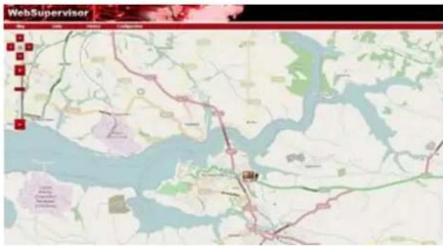
11.2.1.22. You should then be faced with informaon as follows;
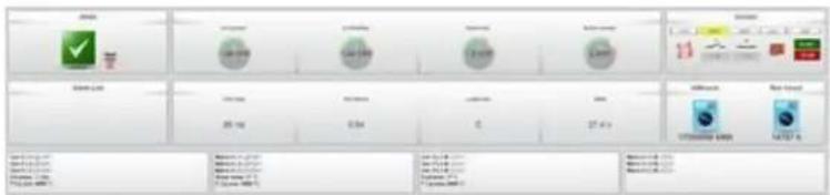
11.2.1.23. Within this screen you can not only monitor the generator, but also start/stop and clear fault codes.
11.2.1.24. If you want to add another user to view this machine, they must request a log in for Web Supervisor with ComAp, then, within your log in, go to 'Units', click on the lock symbol on the unit you want to share and at the boom of the page you will nd 'Add foreign user'.
11.2.1.25. For troublesomeong advice, contact Hyundai Power Equipment on; +44 (0) 1646 687880.
12. DECLARATIONS of CONFORMITY
12.1. Diesel generators
| 10.1.1. 2000/14/EC – | Outdoor Noise Direcve |
| 10.1.2. 2004/108/EC – | Electromagnec Compatibility Direcve |
| 10.1.3. 2006/42/EC – | Machinery Direcve |
| 10.1.4. 2006/95/EC – | Low Voltage Direcve |
13. CONTACT DETAILS
13.1. POSTAL ADDRESS Genpower Ltd, Issac Way, London Road, Pembroke Dock, Pembrokeshire, SA72 4RW. UK.
13.2. TELEPHONE +44 (0) 1646 687880
13.3. FAX +44 (0) 1646 686198
13.4. TECHNICAL E-MAIL service@genpower.co.uk
13.5. WEBSITE www.hyundaipowerequipment.co.uk
14. MANUAL UPDATES
14.1. Our manuals are constantly being reviewed and updated. However if should you nd an error, omission or something you nd unclear please contact your dealer for assistance.
14.2. Our latest manuals are also placed online.
15. WARRANTY
To register your product for the manufacturer's warranty, please visit:
hps://hyundaipowerequipment.co.uk/warranty
For Inquiries, Please Contact:
GENPOWER LTD
Isaac Way, London Road
Pembroke Dock, UNITED KINGDOM, SA72 4RW
T: +44 (0) 1646 687 880 F: +44 (0) 1646 686 198
E: info@hyundaipowerequipment.co.uk
www.hyundaipowerequipment.co.uk


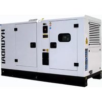
- 1500RPM DIESEL GENERATORS
- CONTENTS
- SAFETY & SAFETY LABELS.
- General safety notes.
- Please note the following safety points.
- This list is not exhaustive and if you are in any doubt contact your dealer.
- CAUTION
- ALL FUELS ARE FLAMMABLE
- Baeries.
- Noise.
- Safety.
- Safety Labels.
- GENERAL USAGE INFORMATION
- MAIN PARTS
- Control panel.
- Oponal ngs for Canopied sets.
- Oil Change.
- COMPONENT LOCATIONS
- Viewed from control panel – canopy removed.
- INSTALLATION
- General outline.
- Transportaon.
- Design for the foundaon.
- For the foundaon design see illustraon below.
- Design for Generator Set Working Room.
- NOTE
- Cooling system.
- Coolant.
- Changing Coolant.
- WARNING
- Cleaning of the cooling system.
- Oil Lubricaon system.
- Fuel System.
- Fuel Tank.
- Fuel SYSTEM.
- Control system.
- Baery.
- Electrical connecons.
- OPERATION.
- Inspecon before use.
- Pre-heater (Opon).
- Connecng to power.
- Starng.
- Remote starng.
- Running.
- Emergency stop.
- Normal stopping procedure.
- Warnings for mis-use.
- Control system operaon.
- Generator control panel operaon
- Start-up generator
- Control panel.
- Generang set control system
- MAINTENANCE
- Control panel.
- Baery.
- USEFUL FORMULAE
- ELECTRICAL INSTALLATIONS WITH OPTIONAL ATS EQUIPMENT
- EARTHING ARRANGEMENTS
- MANUAL CHANGEOVER
- DECLARATIONS of CONFORMITY
- CONTACT DETAILS
- MANUAL UPDATES
- WARRANTY
Brand : HYUNDAI
Model : DHY22KSEm
Category : Generator