
HYTR70 - Gas Slicer HYUNDAI - Free user manual and instructions
Find the device manual for free HYTR70 HYUNDAI in PDF.


| Product Type | Gasoline Powered Trencher |
| Brand | Hyundai |
| Model | HYTR70 |
| Engine Displacement | 70 cc (estimated) |
| Engine Type | 4-stroke, air-cooled |
| Fuel Type | Unleaded gasoline |
| Trenching Depth | Up to 30 cm (12 in) |
| Trenching Width | 10-15 cm (4-6 in) |
| Blade Type | Carbide-tipped teeth |
| Drive System | Chain-driven |
| Weight | Approximately 45 kg (99 lb) |
| Dimensions (L x W x H) | 120 x 60 x 90 cm (47 x 24 x 35 in) |
| Starting System | Recoil start |
| Oil Capacity | 0.5 L (0.13 gal) |
| Fuel Tank Capacity | 3 L (0.8 gal) |
| Maintenance | Regular air filter cleaning, oil change, blade inspection |
| Safety Features | Emergency stop switch, blade guard, operator presence control |
| Spare Parts Availability | Available through authorized dealers; chain, sprocket, air filter, spark plug |
| User Manual | Included in PDF, 36 pages |
Frequently Asked Questions - HYTR70 HYUNDAI
User questions about HYTR70 HYUNDAI
0 question about this device. Answer the ones you know or ask your own.
Ask a new question about this device
Download the instructions for your Gas Slicer in PDF format for free! Find your manual HYTR70 - HYUNDAI and take your electronic device back in hand. On this page are published all the documents necessary for the use of your device. HYTR70 by HYUNDAI.
USER MANUAL HYTR70 HYUNDAI
natural_image
Technical line drawing of a mechanical robotic arm with articulated arms and conveyor system (no text or symbols)| CONTENTS | PAGE NO.S | |
| 1 | SAFETY | 3 - 8 |
| 2 | PART LOCATIONS | 9 |
| 3 | ASSEMBLY | 10 - 12 |
| 4 | PRE OPERATION CHECKS | 13 - 14 |
| 5 | STARTING PROCEDURE | 15 - 16 |
| 6 | STOPPING PROCEDURE | 16 - 17 |
| 7 | OPERATING INSTRUCTIONS | 18 - 22 |
| 8 | MAINTENANCE | 23 - 28 |
| 9 | STORAGE & TRANSPORTATION | 28 - 29 |
| 10 | TROUBLE SHOOTING | 30 |
| 11 | SPECIFICATION | 31 |
| 12 | DECLARATION OF CONFORMITY | 32 |
| 13 | RECYCLING & PRODUCT DISPOSAL | 33 |
| 14 | CONTACT DETAILS | 34 |
| 15 | WARRANTY | 34 |
1. SAFETY
1.1 General Safety Notes.
1.2 The operator of the machine is responsible for, and has a duty of care in making sure that the machine is operated safely and in accordance with the instructions in this user manual. Keep the manual safe and pass it on if the machine is loaned or sold to another user.
1.3 Please note the following safety points.
1.4 The machine should never be left it in a condition which would allow an untrained or unauthorised person/s to operate this machine.
1.5 All due care and diligence should be taken by the operator for the safety of and with regard to those around whilst using the machine.
1.6 Some or all of the following - warning signs, symbols and/or PPE pictograms may appear throughout this manual. You MUST adhere to their warnings. Failure to do so may result in personal injury to yourself or those around you.
! DANGER
Indicates a hazard, which, if not avoided, could result in serious injury or death.
! WARNING
Indicates a hazard, which, if not avoided, could result in serious injury.
! CAUTION
Indicates a hazard which, if not avoided, might result in minor or moderate injury.
NOTE
Indicates a situation that could easily result in equipment damage.
READ and keep the manual safe and pass it on if the machine is loaned or sold to another user.
You MUST fully understand all instructions to ensure you use and operate the machine safely.
Appropriate Personal Protective Equipment (PPE), MUST be worn at all times when operating or repairing the machine.



Carbon Monoxide (where applicable).

Carbon monoxide is a colourless and odourless gas. Inhaling this gas can cause death as well as serious long term health problems such as brain damage.
The symptoms of carbon monoxide poisoning can include but are not limited to the following; Headaches, dizziness, nausea, breathlessness, collapsing or loss of consciousness.
Carbon monoxide poisoning symptoms are similar to flue, food poisoning, viral infections and simply tiredness. It is quite common for people to mistake this very dangerous poisoning for something else.
To avoid carbon monoxide poisoning DO NOT use Petrol/Diesel powered equipment inside any of the following; Home, garage, tent, camper van, mobile home, caravan or boat. This is not exhaustive and if you are in any doubt contact your dealer.
If you think you have or someone around you has been affected by carbon monoxide poisoning;
Get them fresh air immediately, by leaving the affected area or by opening doors and windows. If safe and practical to do so make sure that the machine is turned off. DO NOT enter a room you suspect of having carbon monoxide present – instead call the emergency services.
Contact a Doctor immediately or go to Hospital – let them know that you suspect carbon monoxide poisoning.
DO NOT use in an enclosed area or moving vehicle.
1.20
General Fuel Safety (where applicable).

CAUTION
ALL FUELS ARE FLAMABLE
Fire Hazard – keep fuel away from all sources of ignition for example heaters. Lamps, sparks from grinding or welding.
1.21

DO NOT carry out hot work on tanks that have contained fuel.
ALWAYS keep the work area tidy.
ALWAYS clean up spills promptly using absorbent granules and a lidded bin.
ALWAYS dispose of waste fuels correctly.
1.22 1.23 1.24 1.25
1.30
Fueling/De-fueling (where applicable).

CAUTION
ALL FUELS ARE FLAMABLE
1.31
1.32
ALWAYS fuel and defuel in a well ventilated area outside of buildings.
ALWAYS wear correct, suitable and fit for purpose Personal Protective Equipment (PPE), suggested items are but not limited to safety gloves, overalls.


1.33
1.34
When fueling/de-fueling ALWAYS avoid inhaling fumes.
When de-fueling ALWAYS use a proper fuel retriever.
1.35 1.40 1.41 1.42 1.43 1.44 1.45

ALWAYS carry fuel in the correct and clearly marked container.
Electrical Safety (where applicable).
Electricity can kill – NEVER work on LIVE/ENERGISED equipment.
Prior to carrying out any maintenance work you MUST identify electrical isolation methods and isolate all electrical supplies.
Prior to use and with all electrical supplies isolated, you MUST check all electrical cables, plugs and connectors for the following;
Are intact and have no signs of damage, to include but not limited to bare wires, chaffing, cuts and loose wiring.
If there are any signs of damage, the damaged item MUST be taken out of service until the damage has been repaired by an electrically competent person.

All trailing cables should be routed so as not to cause any kind of trip hazard.
NEVER work on or near electricity with wet hands, wet clothing and wet gloves.
Batteries (where present).
Batteries present a risk if they become damaged by the possible leaking of electrolyte. This electrolyte is an acid and can cause serious burn injuries. Care should be taken when working on or near them. NOTE the electrolyte may be in a liquid or gel form.
Should you come in to contact with electrolyte you should;
Remove all clothing contaminated with electrolyte. If you cannot remove then saturate them in water.
Get medical assistance as soon as possible. You must advise the medical staff of the type of acid.
Lead/acid battery = dilute sulphuric acid.
Nickel/cadmium = potassium hydroxide alkali electrolyte.
Use fresh running water to wash off excess electrolyte, continue this until medical assistance arrives. Make sure that you do not was the electrolyte to another part of your body or face.
If electrolyte comes in to contact with Eyes the electrolyte needs to be immediately washed away with large amounts of water. Make sure that you do not wash the electrolyte to another part of your face or body.
Gasses from charging batteries are highly flammable and great care should be taken to charge in well ventilated areas.

There is an explosion risk if the battery terminals are short circuited, when connecting/disconnecting ALWAYS exercise great care so that the terminals or battery leads are NOT allowed to touch and cause a spark. ALWAYS use suitable insulated tools.
Vibrations (where applicable).
Prolonged use of hand held (operated) machines will cause the user to feel the effects of/from vibrations. These vibrations can lead to white finger (Raynaud's phenomenon) or carpal tunnel syndrome. This condition reduces the ability of the hand to feel and regulate temperature, causing numbness and heat sensations and may cause never damage and circulatory tissue death.
Not all factors that lead to white finger disease are known, but cold weather, smoking and other diseases that affect blood vessels and blood circulation as well as large and long-lasting impact of shocks are considered factors in the formation of white finger. Note the following to reduce the risk of white finger and carpal tunnel syndrome;
Wear gloves and keep your hands warm.
Take regular breaks.
All of the above precautions may help reduce the risk of white finger disease but not rule out the carpal tunnel syndrome. Long-term and regular users are therefore recommended to observe the condition of your hands and fingers. Seek medical attention immediately if any of the above symptoms should occur.
Noise (where applicable).
The operating noise of the machine can damage your hearing. Wear hearing protection such as earplugs or ear defenders to protect your hearing. Long-term and regular users are advised to have hearing checked regularly. Be especially vigilant and cautious when hearing ear protection because your ability to hear alarm warnings will be reduced.
Noise emissions for this equipment is unavoidable. Carry out noisy work at approved times and for certain periods. Limit the working time to a minimum. For your personal protection and protection of people working nearby it is also advisable for them to wear hearing protection.

See Certificate of Conformity section for Outdoor Noise declaration of conformity.
MACHINE SPECIFIC SAFETY
General Machine Safety.
Read the owner's manual carefully to understand how to operate this machine properly.
You should NEVER use the machine when;
Wearing loose clothing, barefoot or sandals.
Under the influence of drink or drugs or as a result of having taken medication for cold or flu, or any other times when a possibility exists that your judgement might be impaired or that you might not be able to operate the machine properly and in a safe manner.
Suffering from exhaustion or lack of sleep.
When the ground is slippery or when other conditions exist which might make it not possible to maintain a steady posture.
At night, at times of heavy fog, or at any other times when your field of vision might be limited and it would be difficult to gain a clear view of the area.
During rain storms, lighting storms, at times of strong or gale force winds, or at any other times when the weather conditions might make it unsafe to use this product.
NEVER run the engine indoors. The exhaust gasses contain harmful carbon monoxide.
When using this machine for the first time and before actual work, you MUST learn how to handle the machine from an experienced or skilled person.
Limit the amount of time using the machine continuously to somewhere around 10 minutes per session and take 10 to 20 minutes of rest between sessions. Also try to keep the total amount of work in a single day limited to 2 hours or less.
NEVER allow children or anyone unable to fully understand the directions given in this manual to operate this product.
Make sure you keep this manual handy so you may refer to it whenever questions arise and ensure you pass this manual on if the machine is loaned or sold.
Correct Personal Protective Equipment (PPE) MUST be worn at all times when operating or repairing this machine. This should include but is not limited to;







2. PART LOCATIONS
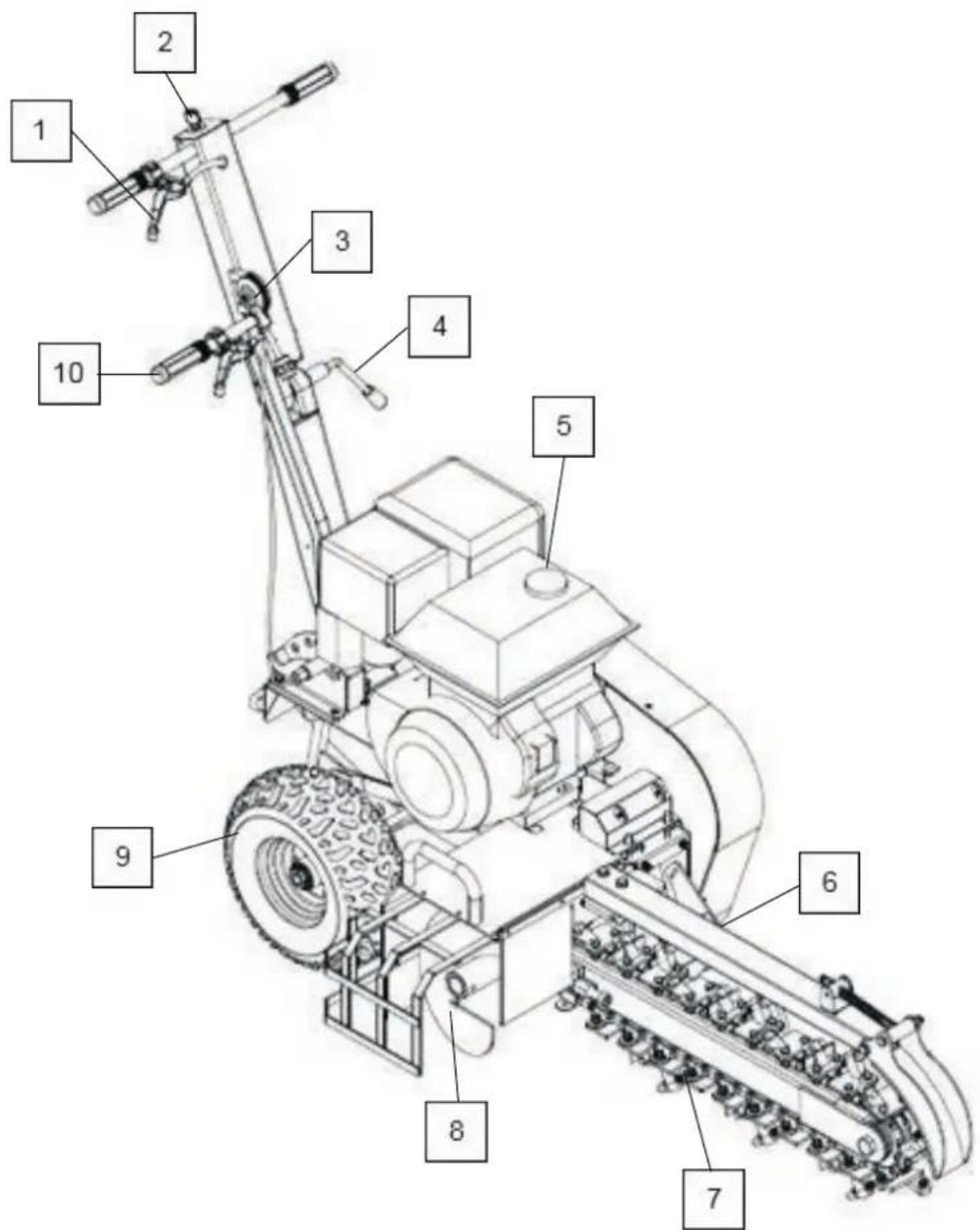
| 1 | Wheel Lock Lever | 6 | Guide Wheel |
| 2 | Ignition Key | 7 | Cutting Chain |
| 3 | Throttle Lever | 8 | Auger |
| 4 | Handle Adjustment Lever | 9 | Wheels |
| 5 | Engine | 10 | Depth Adjustment Lever |
3. ASSEMBLY

CAUTION
Parts of this machine are heavy.
We recommend seeking assistance when unpacking and assembling this machine.
Check all parts have been supplied and are in good condition before assembly.
HANDLE ASSEMBLY

| 1 | Handlebar | 6 | Depth Gauge Handle |
| 2 | M16 Bolt | 7 | Handle Adjustment Lever |
| 3 | M8 x 20 Bolt | 8 | M8 Bolt |
| 4 | Lower Handle | 9 | Locking Pin Lever |
| 5 | Depth Gauge Selector | 10 | Main Chassis |
3.0
Attach the depth gauge handle (6) to the depth gauge selector (5).
Place an M8 bolt (8) through the mounting points on the depth gauge handle, through the corresponding holes in the shaft.
Mount the lower handle (4) to the main chassis (10) and secure with M8 bolts (3).
Attach the handlebar (1) to the lower handle (4) by sliding an M16 bolt (2), through both sections and secure in to the handlebar adjustment lever (7).
Check no cables have become trapped or snagged.
BLADE ASSEMBLY

| 1 | Chain Guard | 7 | Chain Tensioning Nut |
| 2 | M8 Bolt | 8 | Chain Tensioning Bolt |
| 3 | Split Link | 9 | Chain Arm |
| 4 | Split Pins | 10 | M8 Bolt |
| 5 | Chain & Cutting Teeth | 11 | Guide Wheel |
| 6 | Bar |
Slide the chain arm (9) over the bar (6).
Back off the chain tensioning nut (7) and bolt (8) so they are as far back as possible.
The chain and cutting teeth assembly (5) will need to be split in order to be installed.
There will be a removable link (3) in the chain to allow you to split the chain.
Locate the removable link, remove the split pins (4) and then remove the link. The chain will now split.
Pull the chain (5) around the drive shaft housing underneath the machine so that the split link lies on the top of the chain arm (9).
NOTE: Ensure the teeth are facing in the right direction.
Lift the chain on to the drive gear and pull the chain around the idler gear at the front of the chain arm (9).
Bring both ends of the chain together and replace the split link and split pins.
Advance the chain tensioning bolt (8) to remove slack from the chain (5), until there is between 10 – 20mm of slack when you pull the underside of the chain away from the chain arm.
When the tension is correct, tighten the chain tensioning nut (7) to lock the chain tension in place.
Attach the guide wheel (11) to the main chassis using M8 bolts (10).
Attach the chain guard (1) to the main chassis using M8 bolts (2).

NOTE
The machine is shipped without fuel or oil although traces of petrol or oil from the manufacturing process may be present.
It is essential to add adequate engine oil of the correct type to the engine before use. Failure to do so may result in severe engine damage that will not be covered by warranty.
You MUST fill and maintain these levels before every operation.
ALWAYS check the petrol and oil levels when the machine is on a flat and level surface.
Fuel Type : Unleaded Petrol
Oil Type : SAE30 Mineral Oil or SAE15w40 Mineral Oil

CAUTION
FOR OUTDOOR USE ONLY
This machine produces carbon monoxide – a poisonous, colourless & odourless gas that can cause death or serious injury.
Petrol is highly flammable, always handle with extreme care and in a well-ventilated area.
Always remove the HT lead from the spark plug when checking the machine or changing parts.
FUEL
Place the machine on a flat level surface in a well-ventilated area away from any sources of ignition and at least 1.5m away from buildings.
Clean the area around the fuel filler cap to prevent dirt or debris entering the fuel tank.
Unscrew the fuel filler cap and carefully add fresh unleaded petrol. DO NOT overfill.
Allow a 25mm gap at the top of the tank to allow for fuel expansion.
Once full, refit the fuel filler cap and tighten securely.

natural_image
Close-up of a mechanical component with a central circular opening and two black fasteners (no text or symbols visible)
OIL
4.5 Place the machine on a flat level surface.
4.6 Clean the area around the oil filler cap/dipstick to prevent dirt or debris entering the engine.
4.7 Unscrew and remove the oil filler cap/dipstick and wipe with a clean lint free cloth.
4.8 For machines without a dipstick, the oil level is determined by filling to the upper thread level.
For machines with a dipstick, the oil level is determined by the upper limit level mark on the dipstick.
4.9 Slowly fill with oil to the correct level, stop occasionally to check the level.
DO NOT overfill.
4.10 You MUST check the oil level before starting each session.

natural_image
Illustration of a fish jumping from a container into a tank with water flowing (no text or symbols)5. STARTING PROCEDURE

NOTE
This machine is shipped WITHOUT Oil and Fuel and will require filling BEFORE use. Failure to do so will result in engine damage that will not be covered by the warranty.
Recommended Oil: SAE30 Mineral Oil or SAE15w40 Mineral Oil Recommended Fuel: Unleaded Petrol.

CAUTION
Before starting, ensure the machine is clear of materials and all non-essential persons.
5.0
Turn the ignition switch to the ON position.

natural_image
Close-up of a white circular switch with 'ON' and 'OFF' labels on its side, mounted on a black surface (no additional text or symbols)COLD START: Move the choke lever left to the START position. WARM START: Use half choke if warm or no choke if hot.
Move the fuel tap to the ON position.
Move the throttle lever to the MIDDLE position.
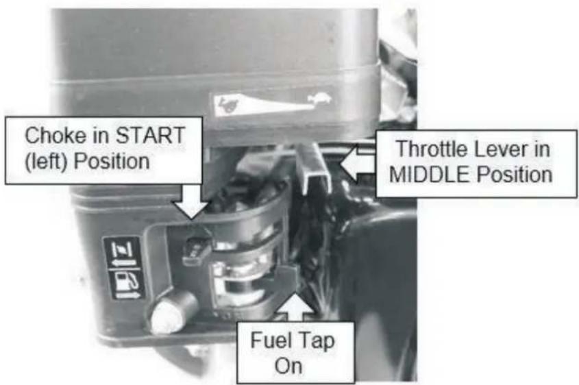
ELECTRIC START: Turn the ignition key to the RUN position.
Do not hold for longer than 5 seconds per starting attempt.
Release the key once the engine has started.
RECOIL START: Place one hand on the machine and using your other hand, pull the recoil start handle until you begin to feel resistance.
Once you feel resistance, pull the handle swiftly.
Repeat until the engine starts.
DO NOT let go of the recoil handle, instead return the handle slowly.

Once the engine has started, reduce the choke by slowly moving the lever right to the RUN position.
If the engine falters, move the choke between the START/RUN and adjust until the engine runs smoothly.
Once the engine has warmed up, move the throttle lever to the left to accelerate the engine to the desired working speed.

6. STOPPING PROCEDURE

CAUTION
You MUST allow the cutting head to come to a complete stop and switch the engine OFF before carrying out any maintenance on this machine.
6.0 Before stopping the machine, allow the engine to cool down by moving the throttle lever to the SLOW position and allowing the engine to idle under no load for 30 seconds.
6.1 Turn the ignition key to the OFF position.
6.2 Turn the power switch to the OFF position.
6.3 Turn the fuel tap left to the OFF position.

7. OPERATING INSTRUCTIONS

WARNING
You MUST STOP using the machine if any of the following occur.
The engine speed changes with no control.
In case of misfire or unusual noise.
In case of high vibration.
If the belts are slipping.
In rain or stormy weather.

CAUTION
If you are not familiar with this type of machine you should seek advice and guidance from your dealer.
DO NOT attempt to lift or move the machine with the engine running.

CAUTION
FOR OUTDOOR USE ONLY
This machine produces carbon monoxide – a poisonous, colourless gas that can cause death or serious injury.
Petrol is highly flammable, always handle with extreme care and in a well-ventilated area.
ALWAYS remove the spark plug HT lead from the spark plug when checking the machine, refuelling or changing parts.
This machine has been designed for digging narrow trenches up to 600mm deep (depending on model).
Before use you MUST check for any buried obstacles such as water pipes or electricity cables.
Your local authority will be able to assist.
Do not attempt to use the trencher on hard surfaces such as concrete, stone or rock or on tree roots, heavy clay soil or other problematic surfaces.
Always check the cutting teeth and chain tension before using the machine.
Worn or damaged parts must be replaced before operation.
Trenching depth may vary depending on the hardness of the ground.
You may need to make several passes at increasing depth to reach the desired trench depth.
If the machine is getting stuck during operation, reduce the depth and investigate other reasons such as suitability of the ground, obstacles etc.
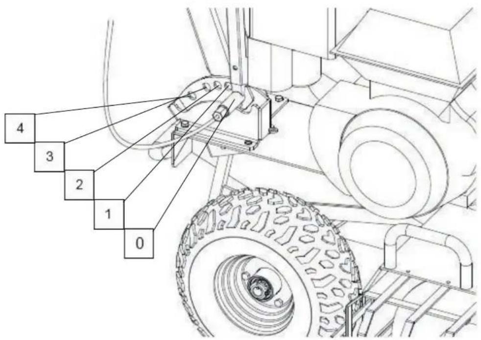
| Work Position | HYTR70 | HYTR150 |
| Depth 0 | 0mm | 0mm |
| Depth 1 | 150mm | 200mm |
| Depth 2 | 250mm | 400mm |
| Depth 3 | 350mm | 600mm |
| Depth 4 | 450mm |
NOTE: All depths are approximate. Actual depth may vary depending upon soil conditions and trencher blade wear.
HANDLEBAR ADJUSTMENT
7.6 Loosen the handle bar adjustment lever until the top section of the handlebar can be adjusted.
7.7 Move the handlebar to a comfortable working position to hold and to raise the front of the machine.
7.8 Tighten the handlebar adjustment handle securely.

natural_image
Diagram of a mechanical device with yellow directional arrows indicating rotational motion (no text or symbols)HANDLEBAR ADJUSTMENT
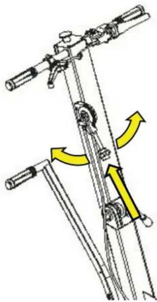
7.9 The trencher uses spring loaded pins to lock the wheels in position when trenching. This reduces forward creep caused by the digging action of the teeth.
7.10 Pull the lock lever on the handlebar to disengage the wheel lock pins.
7.11 Move the machine as required.
7.12 Release the lever to lock the wheels.
NOTE: There may be a small amount of creep before the locking pins fully engage.
THROTTLE
7.13 To adjust the engine speed and engage the chain drive.
7.14 Press and hold the button on the top of the lever.
7.15 Move the lever to the desired speed and release the button to lock in that position.
natural_image
Mechanical linkage diagram showing two vertical poles with directional arrows indicating movement (no text or symbols)Position the machine at the required location.
NOTE: trenching is performed by moving the machine backwards.
Start the machine and allow it to warm up under no load.
Set the trenching arm to the required depth.
Engage the wheel locks.
Increase the engine speed using the throttle to send drive to the chain.
Holding the handlebar firmly with both hands, carefully lower the trenching arm in to the ground.
Allow the teeth to cut in to the ground.
When the guide wheel contacts the ground, the trench is at full depth.
Put weight on to the handlebar to raise the cutting bar.
Disengage the wheel locks and move the machine backwards 100 to 150mm.
Repeat until you have completed the trench.
DO NOT use on slopes greater than 10^ .
DO NOT use the machine if you are tired, consumed alcohol or if you are taking any drugs or medication that can affect your vision, judgement or coordination.
NEVER use the machine indoors or in spaces lacking proper ventilation.
NEVER work in wet conditions, poor traction may cause you to slip and fall.
Make sure you have a proper foothold when using the machine, especially when walking backwards.
Keep your hands and feet away from moving parts and working tools.
Naked flames or sparks in the vicinity are strictly forbidden.
Petrol and its vapours are extremely flammable and carelessness in handling can result in personal injury or fire.
Stop and inspect the machine if you run over or in to anything.
If any damage has occurred you MUST make all the necessary repairs before starting work again.
You must always park the machine on even ground, disengage the drive, activate the wheel locking pins, turn off the engine and wait until all moving parts have stopped before leaving the machine.
Beware of thrown objects.

natural_image
Silhouette of a person running with arrows indicating motion or force direction (no text or symbols)Thrown Objects

natural_image
Abstract black-and-white gear and angular shape design (no text or symbols)Rotating Cutters
Always use the appropriate Personal Protective Equipment (PPE) when using this machine.
Protective clothing and protective equipment cannot eliminate the risk of an accident but wearing proper clothing and the correct equipment will reduce the degree of injury should an accident occur.
8. MAINTENANCE

WARNING
ALWAYS stop the engine, allow it to cool and remove the spark plug HT lead cap before doing any repairs or maintenance.
Check and maintain the fuel level regularly and check the engine oil daily.
At regular intervals, check the tightness of all nuts, bolts and screws.
If the chain and teeth hit an obstacle, stop and check for damage.
Any damage must be repaired before continuing to use the machine.

CAUTION
ALWAYS fuel and defuel in a well-ventilated are with the engine off and cool.
Whilst carrying out any maintenance you MUST wear the appropriate Personal Protective Equipment (PPE).

CAUTION
NEVER use a pressure washer or hose pipe to clean the machine.
Water can penetrate areas of the machine and cause damage to spindles, pulleys, bearings or the engine.
The use of a pressure washer or hose pipe will result in a shortened life span and reduce serviceability.
Shut down the engine, wait for all moving parts to come to a complete stop, remove the spark plug HT lead cap and wait for 5 minutes before carrying out any maintenance.

NOTE
Only use manufacturer recommended parts when servicing or repairing this machine. The use of non-recommended parts may shorten the machines lifespan and void the manufacturer's warranty.
| Each Use | 1^st Month or 20 Hours | Every 50 Hours | Every 6 Months or 100 Hours | Every Year or 300 Hours | ||
| Engine Oil | Check | ● | ||||
| Replace | ● | ● | ||||
| Air Filter | Check | ● | ||||
| Replace | ● | |||||
| Spark Plug | Check | ● | ||||
| Replace | ● | |||||
| Fuel Filter | Clean | |||||
| Replace | ● | |||||
| Spark Arrestor | Clean | ● | ||||
| Fuel Lines | Check | ● | ||||
| Fuel Tank | Check | ● | ||||
| Idle Speed | Check | #● | ||||
| Adjust | #● | |||||
| Valve Clearance | Check | #● | ||||
| Adjust | #● | |||||
We recommend these service items are carries out by an authorised service dealer.

CAUTION
Risk of Burn from hot engine oil.
Allow the oil to cool to WARM before changing the oil.
Warm engine oil will drain more effectively.
Engine Oil: SAE30 Mineral Oil or SAE 15w40 Mineral Oil
Oil Capacity:
8.0 Drain the engine oil while the engine is warm. Warm oil drains more effectively.
8.1 Remove the oil filler/dipstick and place a suitable container under the drain plug.
8.2 Unscrew the drain plug and all the oil to drain, tilt the machine slightly to ensure all the oil has drained, you may require assistance.
8.3 Once the oil has drained, check the drain plug washer and replace if damaged.
8.4 Reinstall the drain plug by hand to avoid cross threading and then tighten with a spanner.
8.5 With the machine on flat level ground, slowly fill the engine with fresh engine oil. Stop occasionally to check the level.
8.6 For machines fitted with a dipstick, fill to the upper level limit on the dipstick. For machines without a dipstick, fill to the upper thread level on the oil fill hole.
8.7 Screw in the oil filler/dipstick securely.
8.8 Wipe up any spilt oil.


natural_image
Simple line drawing of a container with an upward arrow and a handle, no text or symbols present.
NOTE
NEVER run the machine without and air filter being installed.
A dirty filter element affects the engine performance, increases fuel consumption and makes it difficult to start.
If you notice a loss of engine power, check the air filter.
You must ensure the air filter housing is free of dust and debris. DO NOT allow any dust or debris to enter the carburettor.
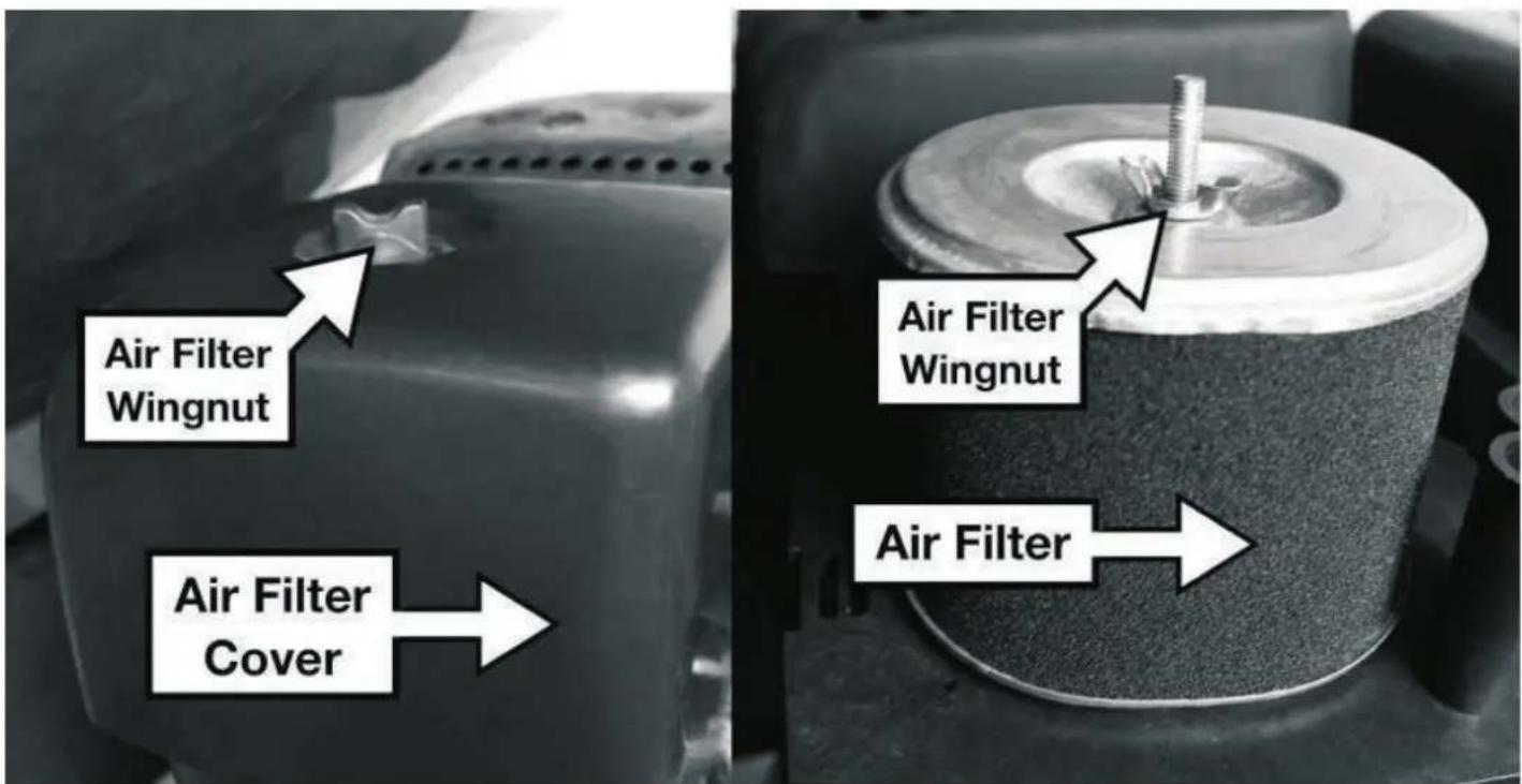
8.9 Remove the air filter cover by unscrewing the air filter cover wing nut and remove the cover.
8.10 Undo the air filter element wing nut and remove the air filter element.
8.11 Ensure no dirt or debris can enter the carburettor chamber.
8.12 Remove the foam filter element from the paper element.
8.13 Inspect the air filter and if it shows any wear or damage then replace immediately.
8.14 Tap the paper element to remove dirt and debris and use a low pressure airline to blow from the inside of the element outwards to remove the remaining dust.
8.15 Wash the foam element in a warm soap solution and allow to air dry.
DO NOT twist the element to dry.
8.16 Once dry, soak the foam element in fresh engine oil and remove any excess.
8.17 Reinstall the foam element over the paper element and reinstall back on to the machine.

CAUTION
ALWAYS allow the engine to cool completely before removing the spark plug.

NOTE
ALWAYS replace the spark plug with the same model.
Incorrect spark plug installation can cause serious engine damage.
DO NOT allow dirt or debris to enter the cylinder bore.
Remove the spark plug HT lead cap.
Using a plug wrench, unscrew the spark plug in an anticlockwise direction.
Inspect the spark plug and plug washer for wear or damage.
If the spark plug or plug washer show any signs of wear or damage then they must be replaced immediately.
Remove carbon deposits from the spark plug electrode by using a soft wire brush.
The spark plug gap should be 0.6 - 0.7mm.
Check the gap using a feeler gauge. The gauge must drag a little when being slid between the electrodes

Refit the spark plug by hand to avoid cross threading.
Once the spark plug seats, tighten with the spark plug wrench to a torque of 12 to 15Nm.
GREASE
Components that require greasing will have grease nipples.
Use a suitable LM2 Lithium Multi-Purpose grease.
It is recommended to grease applicable components every 3 months or more frequently if the machine is used often.
You will require a grease gun to be able to apply the grease.
Attach the grease gun to the grease nipple and inject the grease.

natural_image
Close-up of a vehicle's lower body frame with visible tire and mechanical components, no text or symbols present.9. STORAGE & TRANSPORTATION

CAUTION
ALWAYS ensure the machine has been allowed to cool completely before transportation or storage.
TRANSPORTATION
Drain the fuel tank using a siphon or similar fuel retrieval device into a suitable container for transportation.
Run the engine under no load until the machine stops to remove the remaining fuel from the carburettor and fuel lines.
Allow the engine to cool completely.
Ensure the fuel tap and engine switch are in the off position.
Secure the machine upright in the vehicle so it cannot move during transportation.
Fuel and its vapours are flammable so do not smoke whilst transporting.
STORAGE

NOTE
If the machine is to be stored for periods of more than 30 days then it is essential to prepare the machine for storage correctly.
Failure to do so could result in issues making the machine difficult to start or poor running.

NOTE
DO NOT use a hose pipe or pressure washer to clean the machine.
Water may penetrate vital components and cause damage to the engine or other components.
Drain the fuel tank using a siphon or similar fuel retrieval device, into a suitable container.
Run the engine under no load until the machine stops to remove the remaining fuel from the carburettor and fuel lines.
Allow the engine to cool completely.
Drain he engine oil from the engine following the procedure laid out in the maintenance section and refill with fresh engine oil.
Clean the area around the spark plug and remove the spark plug following the procedure laid out in the maintenance section.
Pour a teaspoon of fresh engine oil down the spark plug hole into the cylinder bore.
Gently pull the recoil start handle 4 to 5 times to coat the cylinder wall with a layer of fresh engine oil.
Refit the spark plug following the procedure laid out in the maintenance section.
Clean the machine using a brush to remove large parts of debris and a moist cloth for other areas.
DO NOT use solvent based cleaning products as these may damage components.
Check the tightness of the cutting teeth and all other nuts and bolts on the machine.
Using a silicone based grease, lightly grease all moving cables and other moving parts.
Top up the grease level at all grease points.
Lightly coat the cutting teeth or other exposed metal parts with a silicone based grease to help prevent corrosion.
Store upright in a cool, dry place away from extremes of temperate change and away from any possible sources of ignition.
Do not store other items on top of the machine.
10. TROUBLESHOOTING

NOTE
If troubleshooting does not resolve your issue, then contact the service dealer. Use only manufacturer recommended parts.
| Problem | Possible Cause | Possible Solution |
| Engine will not start – Fuel System | Choke open | Move choke lever to the closed position |
| Fuel tank empty | Add fuel | |
| Machine stored incorrectly | Check and clean fuel tank and fuel lines | |
| Water in fuel system | Drain and fill with fresh fuel | |
| Carburetor problem | Contact your dealer | |
| Engine will not start – Spark Plug | Incorrect spark plug | Replace with correct spark plug |
| Dirt or carbon build up on electrode | Clean electrode or replace plug | |
| Spark plug short circuit | Replace spark plug | |
| Incorrect plug gap | Check and re-gar spark plug | |
| Petrol/oil on spark plug | Clean spark plug, Start with full throttle | |
| Engine will not start – Low compression | Serious internal engine damage of faulty valves | Contact your dealer |
| Engine lacks power/runs unevenly – Air Filter | Clogged air filter | Clean or replace air filter |
| Engine lacks power/runs unevenly – Fuel System | Machine stored incorrectly with regards to emptying the fuel system | Check and clean the fuel tank, carburetor and fuel lines for sludge. Refill with fresh petrol. |
| Wheel locks not operating | Cable requires adjustment | Adjust cable |
11. SPECIFICATION
| HYTR70 | HYTR150 | |
| Engine | Hyundai OHV Single Cylinder 4 Stroke | Hyundai OHV Single Cylinder 4 Stroke |
| Displacement - cc | 208 | 420 |
| Power - hp | 7 | 15 |
| Fuel Type | Unleaded Petrol | Unleaded Petrol |
| Starting Method | Recoil / Electric | Recoil / Electric |
| Trench Capacity - m/hr | 60 | 60 |
| Trench Depth - mm | 150250350450 | 200400600 |
| Chain | 21 Carbide Alloy Teeth | 27 Carbide Alloy Teeth |
| Chain Length - mm | 1600 | 2000 |
| Chain Speed (max) - m/min | 400 | 400 |
| Dimensions (LxWxH) - mm | 1040X760X850 1120X780X960 | |
| Weight - kg | 145 170 | |
12.0
EC Declaration of Conformity
We hereby declare that the machine detailed in this declaration complies to all the relevant provisions of the following EC directives.
• 2006/42/EC The Machinery Directive
• 2014/30/EU Annex II Electromagnetic Compatibility Directive
- 2016/1628/EC The Emission of Gaseous and Particulate Pollutants from internal Combustion engines
• 2000/14/EC Noise Emissions in the Environment by Equipment for use Outdoors.
And is in conformity with the applicable requirements of the following documents:
• EN ISO 12100:2010, BS EN ISO 14120:2015
• EN474-1:2006+A4:2013
EN474-10:2006+A1:2009
• EN ISO 14982:2009
Declaration for 2000/14/EC Noise Emissions in the Environment by Equipment for use Outdoors.
| Model | Type | Engine size | Measured Sound Power | Guaranteed Sound Power | Engine speed (rpm) |
| HYTR70 | Petrol | 208cc | 97.8dB(A) | 116dB(A) | 3400 |
| HYTR150 | trencher | 420cc |
Product Details
Brand: Hyundai
Model: HYTR70, HYTR150
Description: Petrol stump grinder
Name and address of technical documentation holder and EU distributor:
Genpower Ltd, Isaac Way, Pembroke Dock, Pembrokeshire, SA72 4RW, UK.
Signed by:
RJLevelm
Roland Llewellin, Managing Director
Date: 14/09/2020
13. RECYCLING & PRODUCT DISPOSAL
We do not offer a take back scheme for the recovery of Waste Electrical Electronic Equipment (WEEE) & Batteries.
Instead the responsibility to dispose of WEEE and or Batteries is passed onto you by us.
So when it becomes necessary to dispose of your machine you must take it to your Local Civic Amenity Site.
For further information please contact your Local Authority for disposal advice.
You MUST make sure that all unused oil and fuel is disposed of correctly either beforehand or at your local Civic Amenity Site.
Under NO circumstances must any fuel or oil be put down any drains.
Certain products contain WEEE waste which should not be disposed of in your domestic waste.
You MUST recycle WEEE in accordance with your local authority or recycling centre.
Certain products contain batteries which should not be disposed of in your domestic waste.
You MUST recycle batteries which should not be disposed of in your domestic waste.
Unwanted packaging and materials should be stored and taken to a recycling centre so it can be disposed of in a manner which is compatible with the environment.
The following symbol means you should 'Reduce – Reuse - Recycle'.
We are a member of VALPAK National Compliance Scheme and our registration number is RM08660.
For further information about disposal please contact your Local Authority.
You can also get more advice and guidance about recycling at the following website http://recycle-more.co.uk
Should you pass this product on to another user either sold or loaned, you MUST pass on this user manual.
This will make sure that all other users can use and maintain this machine safely.

natural_image
Symbol of a trash bin crossed with a diagonal line, representing waste sorting or disposal (no text or numbers present)
14. CONTACT DETAILS
| 14.0 | POSTAL ADDRESS | Genpower Ltd, Isaac Way,London Road, Pembroke Dock,Pembrokeshire.SA72 4RW. UK. |
| 14.1 | PHONE | +44 (0) 1646 687 880 |
| 14.2 | SUPPORT | aftersales@hyundaipowerproducts.co.uk |
| 14.3 | WEBSITE | www.hyundaipowerproducts.co.uk |
15. WARRANTY
Proof of purchase will be required before you make a warranty claim.
Full warranty terms and conditions can be found on the HYUNDAI POWER PRODUCTS website:
www.hyundaipowerproducts.co.uk
16. MANUAL UPDATES
| 16.0 | Our manuals are constantly being reviewed and updated.However if you find an error, omission or something you find unclear, please contact your dealer for assistance. |
| 16.1 | Our latest manuals are also placed online. |
Importer:
GENPOWER LTD
Isaac Way, London Road
Pembroke Dock, UNITED KINGDOM, SA72 4RW
T: +44 (0) 1646 687 880 F: +44 (0) 1646 686 198
E: info@hyundaipowerproducts.co.uk
www.hyundaipowerproducts.co.uk
Imported/Distributed by GENPOWER LTD for The United Kingdom & Ireland
- SAFETY
- General Safety Notes.
- ! DANGER
- ! WARNING
- ! CAUTION
- NOTE
- CAUTION
- ALL FUELS ARE FLAMABLE
- Electrical Safety (where applicable).
- Batteries (where present).
- Vibrations (where applicable).
- Noise (where applicable).
- MACHINE SPECIFIC SAFETY
- General Machine Safety.
- PART LOCATIONS
- ASSEMBLY
- HANDLE ASSEMBLY
- BLADE ASSEMBLY
- FOR OUTDOOR USE ONLY
- FUEL
- OIL
- STARTING PROCEDURE
- STOPPING PROCEDURE
- OPERATING INSTRUCTIONS
- WARNING
- HANDLEBAR ADJUSTMENT
- THROTTLE
- MAINTENANCE
- We recommend these service items are carries out by an authorised service dealer.
- GREASE
- STORAGE & TRANSPORTATION
- TRANSPORTATION
- STORAGE
- TROUBLESHOOTING
- SPECIFICATION
- EC Declaration of Conformity
- Product Details
- RECYCLING & PRODUCT DISPOSAL
- CONTACT DETAILS
- WARRANTY
- MANUAL UPDATES
Brand : HYUNDAI
Model : HYTR70
Category : Gas Slicer