8400 - Barre anti-panique Dormakaba - Free user manual and instructions
Find the device manual for free 8400 Dormakaba in PDF.


| Type | Surface Vertical Rod Exit Device |
| Brand | Dormakaba |
| Model | 8400 / F8400 |
| Door Height Range | Up to 8 ft (customizable rod lengths) |
| Mounting | Surface mounted on push side of door |
| Rod Type | Top and bottom vertical rods (top rod standard, bottom rod optional for less bottom rod versions) |
| Latch Type | Top and bottom latches with strike plates |
| Touch Bar | Full-width push bar to retract latches |
| Trim Compatibility | Outside trim with rim cylinder or lever trim (optional) |
| Dogging | Optional cylinder dogging (key-operated) to hold latches retracted |
| Hand Reversal | Field reversible (requires disassembly and rotation of components) |
| Material | Steel (chassis and covers), zinc or aluminum components |
| Finish | Various standard finishes (not specified) |
| Fasteners | Phillips head screws, sex bolts for metal doors |
| Fire Rating | Suitable for fire doors (with additional popper for less bottom rod on fire doors) |
| Standards | Exit device standards, likely UL listed (not explicit) |
| Installation | Requires drilling, template provided, horizontal and vertical reference lines |
| Tools Required | Drill, No. 14 or No. 25 drill bits, Allen wrench, screwdriver |
| Maintenance | Periodic cleaning, lubrication of moving parts, check alignment |
| Spare Parts | Rod guides, latches, strikes, covers, cylinder |
| Warranty | Not specified |
Frequently Asked Questions - 8400 Dormakaba
User questions about 8400 Dormakaba
0 question about this device. Answer the ones you know or ask your own.
Ask a new question about this device
Download the instructions for your Barre anti-panique in PDF format for free! Find your manual 8400 - Dormakaba and take your electronic device back in hand. On this page are published all the documents necessary for the use of your device. 8400 by Dormakaba.
USER MANUAL 8400 Dormakaba
natural_image
Technical line drawing of a mechanical assembly with two parallel supports and a cylindrical rod (no text or symbols)8400/F8400
Surface Vertical Rod Exit Device
Installation instructions
95011760 (1135-31) I8400-14 - 06-2020
| EN |
Table of Contents
1.1 Overall 3
1.2 Door preparation 4
1.3 Prepare strike 4
1.4 Drill door for exit device 5
1.5 Verify door width 5
1.6 Install chassis, exit device and trim 5
1.7 Install covers, end cap, end cover 6
1.8 Verify door height 6
1.9 Latches 6
1.10 Install chassis cover 7
1.11 OPTIONAL: Cylinder dogging 7
1.1 Overall
![STANDARD RODS SHIPPED FOR 7' DOORS. 8' PACKAGE AVAILABLE. MUST BE NOTED AT TIME OF ORDERING. FOR DOORS OVER 8', ORDER ETR PACKAGE PATENTED: U.S. PATENT NO. 4,819,976 #426 top strike 12-24 F.H.P.M.S. Strike angle (fire rated doors over 7' but less than 10'; and all fire rated less bottom rod devices) Top latch assembly 12-24 R.H.P.M.S. Top rod 36-1/4" standard Rod guide components Connecting link (for doors 8' - 10' in height) 8400/F8400 chassis assembly Rod pins install as shown Horizontal reference line Centerline of chassis (vertical reference line) Rod guide components Bottom rod 35" standard Cap plug Popper (fire rated less bottom rod devices only) Bottom latchbolt assembly Cover 8-32 x 1/4" T.H.P.M.S. #439 bottom strike #416 bottom strike (surface) #431 bottom strike (recessed) Touch bar and rail assembly 10-32 x 3/8" [9] Pan head phillips machine screw Dogging (omitted on F8400) End cover Mounting plate End cap (2) #8 x 1" PHTS 12-24 R.H.P.M.S. (2) 8-32 x 1/4" PHTHMS #426 top strike](/content/2026/05/978032/images/6f317b4890f0ed088b8ed63392fcc7327ca8633f04c4c7dd5b7c3225fdf88800.jpg)
1.2 Door preparation
NOTE: SURFACE OF DOOR WHERE EXIT DEVICE IS TO BE INSTALLED MUST BE FLAT. PROPER REINFORCEMENT OF DOOR IS ALSO REQUIRED.
NOTE: BEFORE STARTING INSTALLATION:
- DOOR SHOULD BE FITTED AND HUNG.
- VERIFY DOOR WIDTH WITH BOX LABEL FOR CORRECT LENGTH.
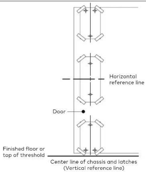
1.2.1 Measure and mark horizontal reference line on push size of door. (40-5/16" [1024] from finished floor, recommended.)
For less bottom rod devices delete bottom latch installation steps.
Less bottom ord devices should not be used where security is a primary concern.
1.2.2 Measure and mark the vertical reference line (center line of chassis) on push side of door. (See dimension below.)

1.3 Prepare strike
For exit only device with no outside trim function
1.3.1 Remove (2) phillips head screws.
1.3.2 Then remove cam bracket assembly.
1.3.3 No additional prep required except for mounting holes. (See spotting template)
1.3.4 Proceed to step 1.4.
For device using outside trim with rim cylinder
1.3.1 Tailpiece should be trimmed 1/8" [3] to 3/16" [5] less than inside face of door.
For device using outside lever trim
1.3.1 See additional instructions packaged in trim carton
For hand reversal:
1.3.1 Remove actuator pin
1.3.2 Remove pin-bracket
1.3.3 Remove actuator
1.3.4 Rotate chassis 180 degrees

1.3.5 Reinstall actuator & pin-bracket in top hole of bracket
1.3.6 Reinsert actuator pin in actuator
1.3.7 Rotate cam on rear of chassis 180 degree
1.3.8 Move screw to lower hole
1.3.9 Reinstall all retaining rings on pins
1.4 Drill door for exit device
1.4.1 Refer to carton label for model and trim numbers before drilling.
1.4.2 Prepare door by using the template enclosed (tape to door).
1.4.3 Horizontal center line and center line of chassis (vertical reference) on template MUST be on horizontal and vertical reference line on door.
CAUTION: If horizontal center line is not maintained, vertical rods will not fit.
NOTE: Vertical reference line is not centerline of cylinder
1.5.1 If no cutting is required; proceed to step 1.6.
1.5.2 If cutting is required, determine length by:
- measuring "A" (hinge side door stop to center of chassis), subtract 2" [51] to determine "B" (length of touch bar and rail dim.).
Centerline of chassis (vertical reference line)
1.5.3 Mark length on rail (cut with touch bar depressed, packing block rotated on edge), then remove packing block and any burrs.
!["A" 1-3/16" [30] min Hinge side of door stop End of rail 1-3/4" [44] min "B" Distance line of tour pin to end](/content/2026/05/978032/images/61ad7f7ae4026e8e9862896936cd8e83a18a52061668b4bf2449e35901d307f7.jpg)
* Depress touch bar to cut to length
![Touch bar rail pin center rail 1-3/4" [44] min Packing block](/content/2026/05/978032/images/c5778e142859a0736d7e34448d614b9d86fa6d2f47a9c604e0095c12b6695814.jpg)
1.6 Install chassis, exit device and trim
Install chassis to touch bar; install exit device and any trim using screws as noted on the spotting template.
1.6.1 Level touch bar/chassis assembly on door, hold mounting plate against touch bar, mark (2) holes and drill.
• No. 25 drill 1" [25] deep for wood doors.
• No. 14 drill 12-24 tap for metal doors.
- 3/8" [10] diam. drill through door for sex bolts
1.6.2 Fasten mounting plate (against rail) to door with (2) round head phillips screws.
1.6.3 For electronic options; drill additional 5/16" [8] diam. hole per detail above.

1.7 Install covers, end cap, end cover
1.7.1 Install top and bottom latch cases using screws as noted on the spotting template.
1.7.2 Install strike angle behind top latch and fire rated less bottom rod devices or fire doors over 8 foot.
1.7.3 Install top and bottom strikes using fasteners as noted on the spotting template.
NOTE: If installing less bottom rod units on fire rated doors, additional popper must be used. See instruction sheet packed with popper for installation.
1.8.1 If cutting rod is required, do not cut threaded end.
1.8.2 Use drill jig supplied as guide to redrill holes.
1.8.3 Install rod guides as shown.
![EXAMPLE 3/16" [5] drill jig rods 1/8" [3] dia. - drill thru CUT](/content/2026/05/978032/images/d8c1f5ab2241e34f686b7c401ae816fd9fb53025c336cafaae5907a58f2d69d1.jpg)
Drill jig (Pt. No. 6400-182-500)
NOTE: DO NOT CUT THREADED END OF ROD
Finished floor line or top of threshold ____
![Equal Rod guide Equal Equal 40-5/16" [1024] Equal](/content/2026/05/978032/images/60e2dfc916f19668ccfb9dcfe41dd3b107305d9ac422bb690a9c552c6b93a63e.jpg)
| Door height | Top rod length |
| 6'8" 32-1/4" | |
| 6'10" 34-1/4" | |
| 7'0" 36-1/4" | |
| 7'2" 38-1/4" | |
| 7'4" 40-1/4" | |
| 7'6" 42-1/4" | |
| 7'8" 44-1/4" | |
| 7'10" 46-1/4" | |
| 8'0" 48-1/4" |
1.9 Latches
1.9.1 Install threaded ends of rods to top and bottom latches.
1.9.2 Install top and bottom latch covers with (4) No. 8-32 truss head phillips machine screws.
1.9.3 Install rod guides over rods. Secure rod guides to door equal distance between top and bottom latches and chassis. (See step 1.8 above.) Use No. 30 drill for (4) #8 x 2" [25] F.H.P.T.S.
1.9.4 Push upward on top rod allowing top latch bolt to retract and be captured by tripping lever fully.
1.9.5 Depress and hold touch bar to hold actuator fully upward.
1.9.6 Rotate rod right (clockwise) to shorten and left (counter-clockwise) to lengthen until hole in rod aligns with hole in top of bell crank. Insert rod pin. Do not bend, pin will be captured by cover once installed. Release touch bar.
1.9.7 * Lift up on bottom rod and align hole in rod and bell crank. Insert pin only.
1.9.8 * Feel to see if bottom of latchbolt is flush across cover. If so, install cover. If not, remove pin, then lengthen or shorten rod as required until latchbolt is flush. Reinstert pin and secure by installing cover.
1.9.9 Depress tripping lever allowing latches to extend.
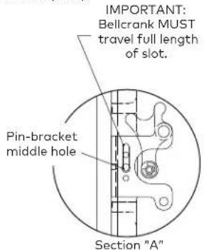
1.9.10 Depress touch bar slowly. Release touch bar, latches should remain retracted, being held by tripping lever. Both latch bolts should be flush across covers. Bell crank should travel full length of slot. (See Sec. A.) If outside trim is used check to ensure its function at this time.
1.9.11 Adjust strikes if necessary.
1.9.12 * Omit Step 1.9.7 and 1.9.8 when installing less bottom rod device (LBR).
1.10 Install chassis cover
Install chassis cover, latch covers and endcover using (10) 8-32 x 1/4" [6] THPHMS and end cap with (2) #8 x 1" [25] PHFHTS screws.
1.11 OPTIONAL: Cylinder dogging
![3/64" [1] allen wrench #4-40 x 7/16" [11] set screw spacer ring (when req'd) 1" [25] min 1-1/8" [29] max Minimum/maximum lock cylinder height 5/16" to 11/32" [9] 3/4" [19] min. dormakaba cylinder supplied #90X10SC118 Touch Bar Assembly Cam Detail dormakaba #10](/content/2026/05/978032/images/ab74fbb9626ff757af9eda5c66a32f71f298c8839dcffa92c3ffdf12f084d08f.jpg)
1.11.1 Thread mortise cylinder into touch bar assembly (see above)
1.11.2 Snug (1) #4-40 x 7/16" set screw with allen wrench (DO NOT OVER TIGHTEN)
1.11.3 Depress touch bar and turn key clockwise to dog and counter clockwise to release.
NOTE: CYLINDER MUST BE INSTALLED WITH TOP OF CYLINDER AWAY FROM CHASSIS (See above)
- 8400/F8400
- Surface Vertical Rod Exit Device
- Installation instructions
- Table of Contents
- Overall
- Door preparation
- NOTE: SURFACE OF DOOR WHERE EXIT DEVICE IS TO BE INSTALLED MUST BE FLAT. PROPER REINFORCEMENT OF DOOR IS ALSO REQUIRED.
- NOTE: BEFORE STARTING INSTALLATION:
- Prepare strike
- For exit only device with no outside trim function
- For device using outside trim with rim cylinder
- For device using outside lever trim
- For hand reversal:
- Drill door for exit device
- Install chassis, exit device and trim
- Install covers, end cap, end cover
- Latches
- Install chassis cover
- OPTIONAL: Cylinder dogging
Brand : Dormakaba
Model : 8400
Category : Barre anti-panique