
Clarity X - Audio Effects TC ELECTRONIC - Free user manual and instructions
Find the device manual for free Clarity X TC ELECTRONIC in PDF.


| Product Type | Digital Reverb/Effects Processor |
| Brand | TC Electronic |
| Model | Clarity X |
| Category | Audio Effects |
| Dimensions (HxWxD) | 1.75" x 19" x 6.5" (44 x 483 x 165 mm) |
| Weight | 2.5 kg (5.5 lbs) |
| Power Supply | External 9V DC adapter (center negative, 600 mA) |
| Input Connections | 2 x XLR/TRS combo jacks (stereo) |
| Output Connections | 2 x XLR (balanced), 2 x TS (unbalanced) |
| MIDI I/O | In, Out/Thru |
| Sample Rate | 24-bit / 96 kHz |
| Effect Types | Hall, Plate, Room, Spring, Inverse, Shimmer, Modulated |
| Presets | 99 factory + 99 user |
| Controls | Rotary encoders, soft buttons, OLED display |
| Bypass Mode | True bypass (relay) |
| Construction | Steel chassis, anodized aluminum front panel |
| Included Accessories | Power supply, rack ears, quick start guide |
| Maintenance | Wipe with dry cloth; avoid solvents |
| Safety Certifications | CE, FCC, RoHS |
| Repairability | Professional service only; no user-serviceable parts |
Frequently Asked Questions - Clarity X TC ELECTRONIC
User questions about Clarity X TC ELECTRONIC
0 question about this device. Answer the ones you know or ask your own.
Ask a new question about this device
Download the instructions for your Audio Effects in PDF format for free! Find your manual Clarity X - TC ELECTRONIC and take your electronic device back in hand. On this page are published all the documents necessary for the use of your device. Clarity X by TC ELECTRONIC.
USER MANUAL Clarity X TC ELECTRONIC
natural_image
Product display of a Clarity X audio recording device with external microphone and USB cable (no visible text or symbols on main components)tc electronic
Safety information 1
| Important safety instructions 2 | |
| Warning | 3 |
| Caution | 4 |
| Service | 5 |
| EMC/EMI | 6 |
About this manual 7
| Getting support 9 |
Before you get started 10
| Register your product 11 |
| Stay up-to-date on loudness 12 |
Unpacking and setup 13
| Package contents 14 | |
| Licenses | 15 |
Software: TC Icon and
| Clarity X firmware 16 |
| Finding and installing TC Icon software - Microsoft Windows 18 |
| Finding and installing TC Icon software - OS X 20 |
Clarity X: An introduction 22
| Clarity X core features | 23 |
| Calibrated Listening | 23 |
| Visual feedback | 24 |
| Speech intelligibility | 24 |
| Hearing loss protection | 24 |
| Clarity X Clock and Jitter Rejection | 25 |
| Clarity X signal flow diagram | 26 |
Clarity X - Basic concepts
| and operation | 27 |
| Operating Clarity X | 28 |
| Hardware versions | 28 |
Clarity X presets 28
Clarity X status indicators and ports 29
| Front panel indicators | 30 |
| Front panel reset button | 32 |
| Back panel connectors | 33 |
Setting up Clarity X 37
| Networking basics and troubleshooting | 39 |
| Quick Setup | 43 |
| Keeping your Clarity X up-to-date | 44 |
Basic operation using
| TC Icon software | 45 |
| TC Icon software – introduction | 46 |
| Basic TC Icon operation | 47 |
| TC Icon faders | 48 |
| TC Icon on-screen keyboard | 49 |
Accessing Clarity X 50
| Operating multiple computers and/or TC HD devices in one network | 52 |
| Scanning and rescanning a network for devices | 53 |
Obtaining Clarity X status information 54
| Clarity X status page | 55 |
Setting up audio and syncing 57
| Setting up audio and syncing - introduction | 58 |
| Signal routing | 59 |
| Clock Setup | 61 |
| MADI setup | 65 |
| Speaker Set configuration | 66 |
| Configuration page | 66 |
| Bass Management page | 68 |
| Audio formats and bass management modes - overview | 69 |
EQ page 74
Phones setup 76
Speaker Set calibration 78
| Speaker Set calibration – introduction | 79 |
| Manual Calibration 85 | |
| Alternative sweet spots | 90 |
The Library: Recalling, storing and deleting settings 91
| Studio, Project, Routing, Engine and M2 presets | 92 |
| The Library concept | 95 |
| Recall page | 96 |
| Store page | 97 |
| Delete page | 99 |
| Bank page | 100 |
Signal Source and
| Speaker Set configuration | 101 |
| Main Edit page 102 | |
| Tone page | 105 |
Clarity X Main view –
| Meters and Operation | 107 |
| Clarity X main view – introduction | 108 |
| Main view – left pane – page 1 | 109 |
| Main view – left pane – page 2 | 111 |
| Main view – right pane – page 1 | 112 |
| Main view – right pane – page 2 | 114 |
| Product | Clarity X |
| Product (firmware) version | 1.3.00 – Build 3275 |
| Document | Reference manual |
| Document version / date | 2016-10-18 |
| You can download the most current version of this manual from the support page for Clarity X. | |
tc electronic
Downmix and other TC Icon Setup 164
processing functions 115 Accessing the Icon Setup pages 165
Edit Format Page 116 Info page 166
Dose Metering 119 Security page 168
Hearing Loss 120 Joystick page 169
Sound Exposure 120 UI (user interface) page 170
Color page 171
Clarity X Remote Control 124
Using the Remote Control 125 Appendix 1: Links and additional
Configuring the Remote Control 127 information 173
M2 – The LM8 Meter 128 TC Electronic on... 174
LM8 - introduction 129 TC HD resources 174
LM8-Basic use and setup 132 Product-related information 174
LM8 Radar Page 134
LM8 Main page 137 Appendix 2: Acoustics 175
LM8 Setup page 141 Introduction 176
LM8 Statistics page 143 Sabine's formula 178
LM8 log files 144 Absorbers 179
M1 Meter configuration 149 Standing waves 181
M1 - introduction 150 Comb filtering 184
Rear wall cancellation 186
Preferences 152 Subwoofers 187
Preferences page 153 Bass management 188
The LFE Channel 189
Clarity X firmware update and Delaying monitors 190
Device Reset 156 Line-up and calibration 191
Finding and installing Clarity X
firmware – Microsoft Windows 158 Technical specifications 194
Finding and installing Clarity X
firmware - OS X 160
Resetting your Clarity X 163
Safety information
Clarity X software version 1.3.00 – Build 3275 – Reference manual (updated 2016-10-18)
Important safety instructions

The lightning flash with an arrowhead symbol within an equilateral triangle, is intended to alert the user to the presence of uninsulated “dangerous voltage” within the product’s enclosure that may be of sufficient magnitude to constitute a risk of electric shock to persons.

The exclamation point within an equilateral triangle is intended to alert the user to the presence of important operating and maintenance (servicing) instructions in the literature accompanying the product.
- Read these instructions.
- Keep these instructions.
- Heed all warnings.
- Follow all instructions.
- Do not use this apparatus near water.
- Clean only with dry cloth.
- Do not block any ventilation openings. Install in accordance with the manufacturer's instructions.
-
Do not install near any heat sources such as radiators, heat registers, stoves, or other apparatus (including amplifiers) that produce heat.
-
Do not defeat the safety purpose of the polarized or grounding-type plug. A polarized plug has two blades with one wider than the other. A grounding type plug has two blades and a third grounding prong. The wide blade or the third prong are provided for your safety. If the provided plug does not fit into your outlet, consult an electrician for replacement of the obsolete outlet.
-
Protect the power cord from being walked on or pinched particularly at plugs, convenience receptacles, and the point where they exit from the apparatus.
-
Only use attachments/accessories specified by the manufacturer.
-
Use only with the cart, stand, tripod, bracket, or table specified by the manufacturer, or sold with the apparatus. When a cart is used, use caution when moving the cart/apparatus combination to avoid injury from tip-over.
-
Unplug this apparatus during lightning storms or when unused for long periods of time.
-
Refer all servicing to qualified service personnel. Servicing is required when the apparatus has been damaged in any way, such as power-supply cord or plug is damaged, liquid has been spilled or objects have fallen into the apparatus, the appara-
tus has been exposed to rain or moisture, does not operate normally, or has been dropped.
Warning
To reduce the risk of fire or electrical shock, do not expose this equipment to dripping or splashing and ensure that no objects filled with liquids, such as vases, are placed on the equipment.
▶ Use a three wire grounding type line cord like the one supplied with the product.
▶ Be advised that different operating voltages require the use of different types of line cord and attachment plugs.
▶ Check the voltage in your area and use the correct type. See table below:
Voltage Line plug according to standard
| 110-125 V UL817 and CSA C22.2 no 42. | |
| 220-230 V | CEE 7 page VII, SR section 107-2-D1/IEC 83 page C4. |
| 240 V BS 1363 of 1984. Specification for 13A fused plugs and switched and unswitched socket outlets. | |
This equipment should be installed near the socket outlet and disconnection of the device should be easily accessible.
▶ Do not install in a confined space.
- Do not open the unit – risk of electric shock inside.
▶ Mains ground must be connected.
▶ You are cautioned that any change or modifications not expressly approved in this manual could void your authority to operate this equipment.
▶ To completely disconnect from AC mains, disconnect the power supply cord from the AC receptacle.
▶ The mains plug of the power supply shall remain readily operable.
▶ Danger of explosion if battery is incorrectly replaced. Replace only with the same or equivalent type.
▶ Ventilation should not be impeded by covering the ventilation openings with items, such as newspapers, tablecloths, curtains, etc.
▶ Only used at altitude not exceeding 2000 m.

Service
There are no user-serviceable parts inside.
▶ All service must be performed by qualified personnel.
EMC/EMI
This equipment has been tested and found to comply with the limits for a Class B Digital device, pursuant to part 15 of the FCC rules.
These limits are designed to provide reasonable protection against harmful interference in a residential installations.
This equipment generates, uses and can radiate radio frequency energy and, if not installed and used in accordance with the instructions, may cause harmful interference to radio communications. However, there is no guarantee that interference will not occur in a particular installation.
If this equipment does cause harmful interference to radio or television reception, which can be determined by turning the equipment off and on, the user is encouraged to try to correct the interference by one or more of the following measures:
▶ Reorient or relocate the receiving antenna.
▶ Increase the separation between the equipment and receiver.
- Connect the equipment into an outlet on a circuit different from that to which the receiver is connected.
- Consult the dealer or an experienced radio/TV technician for help.
The user may find the following booklet, prepared by the Federal Communications Com-
mission, helpful: "How to identify and Resolve Radio/TV interference Problems." This booklet is available from the US. Government Printing Office, Washington, DC 20402, Stock No. 004-000-0034-4.
For customers in Canada
This Class B Digital apparatus meets all requirements of the Canadian Interference-Causing Equipment Regulations ICES-003.
Clarity X software version 1.3.00 – Build 3275 – Reference manual (updated 2016-10-18)
This manual will help you learn understanding and operating TC Clarity X.
To get the most from this manual, please read it from start to finish, or you may miss important information.
This manual is only available as a PDF download from the TC Electronic website.
Please do not operate Clarity X before you have made all connections to external equipment as described in "Setting up Clarity X" on page 37.
In the subsequent sections of the manual, we assume that all connections are made correctly and that you are familiar with the previous sections.
To download the most current version of this manual, view the product warranty, and access the growing FAQ database for this product, please visit the web page
tcelectronic.com/support/
Getting support
If you still have questions about the product after reading this manual, please get in touch with TC Support:
tcelectronic.com/support/
Before you get started
Clarity X software version 1.3.00 – Build 3275 – Reference manual (updated 2016-10-18)

tc electronic
Before you get started
Register your product
Please register this product so we can inform you about updates and other product-related news. To register your product, please go to:
tcelectronic.com/support/ account-registration/registration/

tc electronic
Before you get started
Stay up-to-date on loudness
There are many aspects to loudness, and keeping track of all of them can be a challenge. This is why TC Electronic has created a dedicated loudness website, where all of these aspects are outlined, explained and discussed. This site is an answer to the question:
"What is loudness – and why is it important?"
Visit the Loudness website at:
tcelectronic.com/loudness/
Unpacking and setup
Clarity X software version 1.3.00 – Build 3275 – Reference manual (updated 2016-10-18)
Package contents
The box includes the following items.
1 x Clarity X unit
▶ 1 x Calibrated 3600A TC Electronic Reference Microphone
▶ 1 x Clarity X Remote Control
1 x Power Cable
LAN Cable
▶ 1 x Quick Start Guide
Clarity X can be purchased either in a basic or in an extended (package) configuration.
Setup
For basic setup information, see "Quick Setup" on page 43.
Clarity X Configurations
| Clarity X Clarity X Package | |
| Remote Included Included | |
| Measurement Microphone Included Included | |
| Stereo and 5.1 Included Included | |
| MADI Ready* Included Included | |
| 7.1 Speaker Sets Optional Included | |
| AES Channel 9-16 Optional Included | |
| EQ on Outputs Optional Included | |
| Digital Cable Optional Included | |
| Analog Cable Optional Included | |
| MADI Licence | Optional Optional |
Licenses
Some Clarity X features are available as optional software licenses. These include:
EQs on speakers
▶ 7.1 Speaker Sets (please note that a license is only required for 7.1 Speaker Sets, but not for processing 7.1 signal sources)
AES I/O 9-16
MADI
There are two types of licenses for Clarity X:
Full (Permanent)
Timed
Obtaining a license
You can obtain a license...
▶ from the TC Electronic web shop at http://store.tcelectronic.com or
through TC Electronic's sales department (see tcelectronic.com/where-to-buy/sales/)
To obtain an optional license, you will need your Clarity X serial number. Alternatively, demo licenses can be activated using the demo license key.
▶ Open the ICON software and navigate to the License page (Frame / System / License) For more information on navigating the Icon user interface, see "Basic operation using TC Icon software" on page 45.
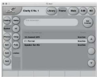
Fig. 1: License page
▶ Select the option you want to acquire a license for (e.g. "Speaker Set EQ").
▶ Click the "Get License" button.
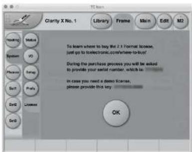
Fig. 2: License Dialog
▶ Follow the on-screen instructions to obtain a license code, or write down the demo license key shown on this page.
▶ Click the OK button.
▶ Enter the license into the Enter license code field and press Enter.
Your license will be activated.
Software: TC Icon and Clarity X firmware
Clarity X software version 1.3.00 – Build 3275 – Reference manual (updated 2016-10-18)
Operating Clarity X requires a TC Icon remote (sold separately) or a computer running the TC Icon software.
When you are working with a system involving one or multiple Clarity X units, you are interacting with two types of software:
1. TC Icon software:
TC Icon is a software application that you install on the computer(s) which you are using to access, configure, operate and update the Clarity X unit(s).
TC Icon software is available for Microsoft Windows and Mac OS X operating systems.
TC Icon software is free and can be installed on multiple computers.
Downloading and installing TC Icon software is described in this section of the Clarity X manual.
2. TC Clarity X firmware:
Clarity X firmware is the software installed on every Clarity X.
Every Clarity X comes pre-installed with the most current firmware version available at the time of production. You can download newer versions of Clarity X firmware from the TC website. Firmware updates will contain bug fixes and/or new features.
Clarity X firmware updates are free.
Use TC Icon software installed on your computer (see above) to transfer firmware to your Clarity X unit(s).
Downloading and installing Clarity X firmware updates is described in "Clarity X firmware update and Device Reset" on page 156.
You should keep both the TC Icon software running on your computer and the software of your Clarity X (the firmware) up to date. Using up-to-date software versions ensures you benefit from bug fixes and the latest features.
Finding and installing TC Icon software – Microsoft Windows
You can download the latest version of the TC Icon software for Microsoft Windows from:
tcelectronic.com/support/software/
On this page, locate the "Clarity X" section.
In this section of the support page, look for "TC Icon software" and click the button representing the latest version of the TC Icon software for Microsoft Windows.

Clarity X
Firmware
+ Show version history

Clarity X Firmware Windows & Mac - Version 1.1 - 1.24 MB
Released: Wednesday, July 1, 2015
TC Icon Software
+ Show version history

Clarity X TC Icon Software Windows - version 8.1-1.8 MB
Released: Wednesday, July 1, 2015

Clarity X TC Icon Software Mac - Version 8.1 - 5.72 MB
Released: Wednesday, July 1, 2015

Clarity X TC Icon Software Version 8.1 - 1.79 MB
Released: Wednesday, July 1, 2015
Fig. 3: Clarity X software on the TC Electronic software download page
Depending on your browser type and configuration, a dialog may be shown asking you what you want to do with this file.
Choose "Save".
The software will be downloaded to your browser's default download location. Usually, this is the "Downloads" folder for your user account.
- Go to the folder containing the ZIP file you just downloaded.
- Right-click the .ZIP file and choose "Extract All..." from the context menu.
A dialog box will allow you to specify where the extracted files should be stored.
▶ Accept the defaults or change the path.
After extracting the ZIP file, you will see a .CAB ("Cabinet") file in Windows Explorer.
▶ Double-click the .CAB file.
An "Icon" application file will be shown.
- Right-click the "Icon" application file and choose "Extract..." from the context menu.
In the dialog box that is shown next ("Select destination"), select a folder where you can easily find the application – e.g., the Windows desktop.
- Click "Extract" to extract the application to the selected destination.
▶ Launch the TC Icon application that you just extracted by double-clicking its icon.
TC Icon will try to establish connections to all connected TC devices on a local network, including your Clarity X.
If a connection cannot be established, please refer to "Networking basics and troubleshooting" on page 39.
If you experience technical problems during software download or installation, please ask a person with administrator privileges on this computer for assistance.
Updating TC Icon software (Windows)
To update the TC Icon software on your computer when a newer version is released,
- quit the TC Icon software if it currently running on your PC,
▶ download and extract the newer version as described in this section and
replace the currently installed version by copying the newer version over it.
Finding and installing TC Icon software - OS X
You can download the latest version of the TC Icon software for OS X from:
tcelectronic.com/support/software/
On this page, locate the "Clarity X" section.
In this section of the support page, look for "TC Icon software" and click the button representing the latest version of the TC Icon software for OS X.

Clarity X
Firmware
+ Show version history

Clarity X Firmware Windows & Mac - Version 1.1 - 1.24 MB
Released: Wednesday, July 1, 2015
TC Icon Software
+ Show version history

Clarity X TC Icon Software Windows - version 8.1 - 1.8 MB Wednesday July 1, 2015


Clarity X TC Icon Software Mac - Version 8.1 - 5.72 MB
Released: Wednesday, July 1, 2015

Clarity X TC Icon Software Version 8.1 - 1.79 MB
Released: Wednesday, July 1, 2015
Fig. 4: Clarity X software on the TC Electronic software download page
Depending on your browser type and configuration, a dialog may be shown asking you what you want to do with this file. Choose "Save".
The software will be downloaded to your browser's default download location. Usually, this is the "Downloads" folder for your user account.
- Go to the folder containing the file you just downloaded.
If you are seeing a .ZIP file, double-click it to extract its contents. However, your browser may already have extracted the contents from the .ZIP file automatically.
After the ZIP file has been extracted, you will see a .DMG ("Disk Image") file in the Finder.
▶ Double-click the .DMG file to mount this disk image.
An "Icon" disk image containing an "Icon" app will be shown.
natural_image
Illustration of a flip phone with no visible text or symbols on its device surfaceFig. 5: TC Icon software app icon
▶ Copy the TC Icon application from the disk image to your hard disk by dragging it to the "Applications" folder, or to another folder where you can easily find it.
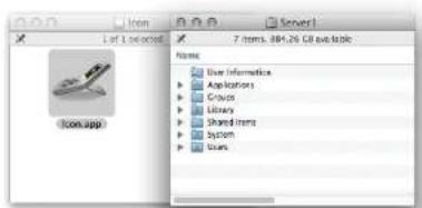
Fig. 6: Moving TC Icon to the OS X applications folder
▶ You can now unmount (eject) the disk image by right-clicking it and selecting "Eject" from the context menu.
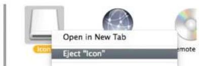
Fig. 7: Ejecting the TC Icon disk image
▶ Launch TC Icon by double-clicking the application.
TC Icon will try to establish connections to all connected TC devices on a local network, including your Clarity X.
If a connection cannot be established, please refer to "Networking basics and troubleshooting" on page 39.
If you experience technical problems during software download or installation, please ask a person with administrator privileges on this computer for assistance.
Running TC Icon software for the first time (OS X)
Depending on your security preferences, you may see a dialog telling you that the TC Icon application cannot be opened because it is from an unidentified developer when you are launching tit for the first time. If you see this dialog, close it, then right-click the application's icon and select "Open" from the context menu. This will open another dialog, allowing you to confirm that you want to run the software.
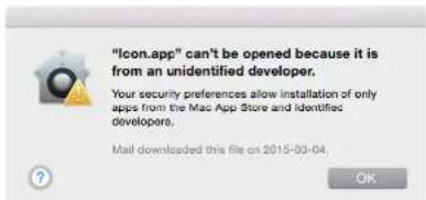
Fig. 8: OS X security warning about application from an unidentified developer
Updating TC Icon software (OS X)
To update the TC Icon software on your computer when a newer version is released,
- quit the TC Icon software if it currently running on your Mac,
▶ download and extract the newer version as described in this section and
replace the currently installed version by copying the newer version over it.
Clarity X: An introduction
Clarity X software version 1.3.00 – Build 3275 – Reference manual (updated 2016-10-18)
Clarity X is an extremely flexible monitor controller, covering channel formats up to 7.1 surround. It also includes several advanced meters, ensuring you will never have to compromise on the clarity and intelligibility of your mix.
Clarity X helps you secure the best foundation for your crucial mix decisions, including monitor calibration, center channel balance, downmix and loudness compatibility and other vital parameters.
Clarity X core features
▶ One-stop calibrated listening – measurement microphone included.
▶ Multiple, high-precision meters for optimum mix decisions.
▶ Helps increase the intelligibility of your production.
Calibrated Listening
Our ears and brain react differently to various listening levels. Voices live in the mid-range – and that has been important throughout evolution. Accordingly, at low levels, our brain emphasizes the mid-range, while we allow more bass and treble at higher listening levels.
Consequently, if you mix at low levels, you would be likely to boost the low and high areas more than you would at a higher listening level.
That is why you should always mix on a calibrated monitoring system: Playback at the same SPL simply ensures that your mixes remain consistent.
The included measuring microphone is perfectly calibrated for Clarity X.
For more information on calibration, see "Speaker Set calibration" on page 78.
Visual feedback
You should always mix with your ears first, but having visual meters as well can be a great help.
Clarity X gives you five dedicated meters covering
▶ Loudness/true-peak,
▶ Center channel balance,
▶ SPL,
Downmix compatibility and
▶ Dose usage.
On the loudness side, you get our brand new LM8 that covers any channel formats up to 7.1 surround.
The best way to check downmix compatibility is to hit the remote and listen to your mix in stereo, but with the Stereo deviation meter you may save some precious time.
In short, let your ears be your pilot – but allow your eyes to be your guide.
For more information, see "Clarity X Main view – Meters and Operation" on page 107 and "M2 – The LM8 Meter" on page 128.
Speech intelligibility
When mixing content with spoken words, it is absolutely crucial that what is being said is clear. Yet this issue is the single most common complaint broadcasters receive today.
Clarity X helps you create mixes with greater intelligibility in many ways, but a key component is the meter showing the Center Ratio.
We have analyzed dialogs from film, drama and TV shows to determine the ideal loudness balance between the center channel (foreground) in a surround mix and the other channels (background).
If the actors mumble or the recording itself is poor, there is little we can do. But we can help you keep an eye on the general balance which just may be what you need to always keep speech intelligibility at its best.
Hearing loss protection
Noise Induced Hearing Loss (NIHL) is quickly becoming a focal point in professional audio as well as in a consumer context.
Obviously, for audio professionals, their ears are their most critical tools, and exposure to high sound pressure levels on a daily basis can build up over time and become a problem one day both from a professional and a personal experience.
The EU's Noise at Work directive and the European Committee for Electrotechnical Standardisation (CENELEC) have issued a set of recommendations for a certain dose of sound exposure over various time frames to prevent NIHL.
To help you monitor and keep track of your daily and weekly dose of sound, the built-in dose meter of Clarity X will calculate and record your dose and show you how many percent you have used so far.
You might want to check your status at the end of the day – and if you find a pattern of over-exposure, you'll be glad that you have the chance to take action before it's becoming a serious problem.
For configuring the Dosage Meter, see "Dose Metering" on page 119 and "Exposure & dose estimation section" on page 154.
Clarity X Clock and Jitter Rejection
Digital audio signals rely on only two components: level and time.
We all know about levels (bits) - but timing is equally important to avoid noise and distortion.
Jitter is unwanted variation of a digital audio signal's timing. It is typically recognized by compromised dynamic range of A/D, D/A and sample rate converters or by clicks and dropouts due to interface breakdown.
A steady digital clock is crucial to the sound quality – especially when one of the above conversions is performed. The clock stability and jitter rejection of Clarity X is based on technology from TC System 6000 and our many years of research providing absolute high-end performance.
The excellent jitter rejection technology of Clarity X is also capable of cleaning up a less-than-perfect digital signal from an external source, thereby tidying up your entire studio timing and optimizing performance. The jitter rejection in Clarity X is placed exactly where you need it the most: At the boundary between the digital and the analog domain, where the D/A converters of your Clarity X convert the signal going to your analog speakers.
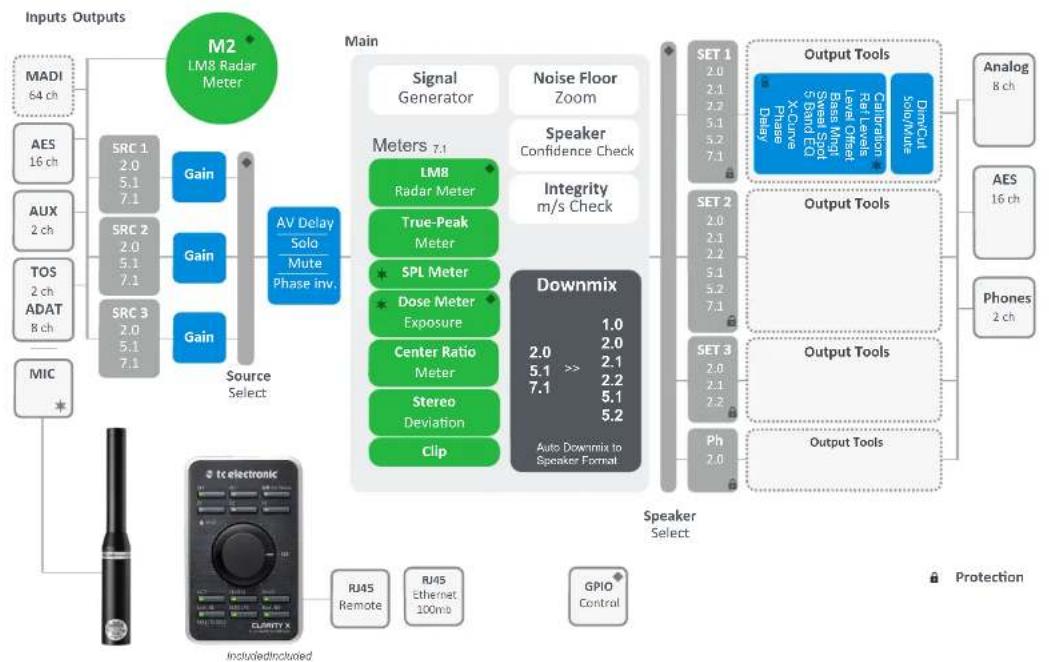
Clarity X signal flow diagram
flowchart
graph TD
    A["Inputs Outputs"] --> B["M2 LM8 Radar Meter"]
    B --> C["Main"]
    C --> D["Source Select"]
    D --> E["Source Select"]
    E --> F["Speaker Select"]
    F --> G["Downmix"]
    G --> H["Output Tools"]
    H --> I["Analog 8 ch"]
    H --> J["AES 16 ch"]
    H --> K["Phones 2 ch"]
    G --> L["Speaker Select"]
    L --> M["Output Tools"]
    M --> N["Analog 8 ch"]
    G --> O["Output Tools"]
    O --> P["AES 16 ch"]
    G --> Q["Phone 2 ch"]
    G --> R["Output Tools"]
    R --> S["Analog 8 ch"]
    G --> T["Output Tools"]
    T --> U["Analog 8 ch"]
    G --> V["Output Tools"]
    V --> W["AES 16 ch"]
    G --> X["Phone 2 ch"]
    G --> Y["Output Tools"]
    Y --> Z["Analog 8 ch"]
Fig. 9: Clarity X signal flow diagram. For more information on a section, please click or tap the respective part of the diagram.
Clarity X – Basic concepts and operation
Clarity X software version 1.3.00 – Build 3275 – Reference manual (updated 2016-10-18)
Operating Clarity X
As you can easily see, Clarity X is a „headless system“ – it has no front panel controls (with the exception of the Reset button).
Clarity X is operated using
▶ the TC Icon software, which you can download from the TC Electronic website and
▶ the Clarity X Remote Control.
While the Clarity X Remote Control allows you to control your studio setup (e.g. by selecting configurations, muting and soloing monitors), you will need TC Icon software to configure all Clarity X signal metering and processing features and update your system.
You can use the same version of the TC Icon software to operate Clarity X and other professional broadcast products from TC Electronic (e.g. a System 6000 MKII).
Accordingly, a significant part of this manual covers operating Clarity X using TC Icon software running on a standard computer, and the screen shots you see are taken from the OS X or Windows versions of this software.
Please invest some time in learning TC Icon's basic concepts – you will benefit from it when operating systems that may include many networked TC signal processors.
Hardware versions
Two Clarity X hardware versions are available.
By default, Clarity X comes with AES inputs and outputs. But as an option, you can choose to add 64 channels via MADI.
You will need to pre-order Clarity X with the MADI option, or send in your Clarity X unit if you want to retrofit it at a later point.
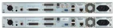
Fig. 10: Clarity X hardware options: With MADI (top) and without MADI (bottom)
Clarity X presets
Clarity X comes with ready-to-use presets based on international standards. More presets will be made available as part of software updates from the TC website. These presets are based on information from broadcasters around the world.
If you feel that an important preset is missing or that a given preset does not work as it should, please get in touch with TC Electronic technical support:
tcelectronic.com/support/
Clarity X status indicators and ports
Clarity X software version 1.3.00 – Build 3275 – Reference manual (updated 2016-10-18)
Front panel indicators

Fig. 11: Clarity X front panel
Clarity X has the following front panel status indicators:
Power
Running
Net
▶ Remote
Sync
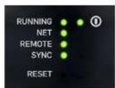
Fig. 12: Clarity X front panel indicators
Running LED
The Running LED indicates the status of the Clarity X unit.
| LED | Status | TC Iconmessage |
| Grey Startup (until all processing is running) | Running - N/A | |
| Green Startup completed, unit available | Running - OK | |
| Red System Error Running - | Sys Error | |
Net LED
The Net LED indicates the status of the network connection to a computer running TC Icon software or a hardware TC Icon.
| LED | Status | TC Icon message |
| Grey No computer or Icon connected | - | |
| Green One or more Icons/Apps connected | Net - This Icon(1), 2 Icons/ Apps(2) ...8 Icons/ Apps(8) | |
| G/G/Y/R | Frame identification - see “Frame Identification pa-rameter” on page 56 | Net - LED blinking |
Remote LED
The Remote LED indicates the status of the remote control (port).
| LED | Status | TC Icon message |
| Grey No Remote connected Remote – | ||
| Green Clarity X remote connected | Remote – OK | |
| Yellow Remote not supported Remote – | ||
| Unsupported | ||
Sync LED
The Sync LED indicates if synchronization to the currently connected signal source has been achieved.
| LED | Status | TC Icon message |
| Grey Start | Startup until I/Os are up and running | N/A |
| Green Sync OK + all inputs OK (No sample slips/repeats) | Inputs OK | |
| Yellow AES input sample slip/re-peat observed | Input Slip | |
| Red No valid clock available No Clock | ||
Front panel reset button
The Reset button on the front panel can be used to reset the IP address of a Clarity X unit or to reset Ethernet communication between Clarity X and a computer when a communication error has occurred.
Resetting the IP address of a Clarity X unit
It may be necessary to reset the IP address of a Clarity X unit. To do so, proceed as follows:
▶ Switch off Clarity X by disconnecting the power supply.
- Insert a straightened paper clip or a similar object into the "Reset" hole on the front panel until it touches the button behind the panel.
- Boot the Clarity X by connecting the power supply while still holding the straightened paper clip onto the Reset button.
Clarity X will boot using its default IP address. The default IP address is 192.168.1.[xx], where [xx] is the last two digits of the device's serial number as printed on its back.
Resetting Ethernet communication
It may be necessary to reset Ethernet communication between Clarity X and a computer during operation. To do so, proceed as follows:
During operation, insert a straightened paper clip or a similar object into the "Reset" hole on the front panel until it touches the button behind the panel, and press the button for approximately 5 seconds until the LEDs start blinking.
This will reset Ethernet communication without interrupting audio streams.
Back panel connectors

Fig. 13: Clarity X back panel connectors (shown with optional MADI ports)
Clarity X has the following back panel connectors:
▶ Microphone input (calibrated)
Line in (3.5mm stereo jack - unbalanced)
▶ Analog Line/Monitor Out
(D-SUB - 8 channels)
▶ AES Inputs & Output Channels 1-8 (D-SUB)
▶ AES Inputs & Output Channels 9-16 (D-SUB)
▶ Optical In (TOS-link)
▶ GPIO
Ethernet 1
Ethernet 2
▶ Remote in
Power inlet
The Clarity X unit itself may be mounted in a remote location, for example a machine room. For fast and daily access, consider using extension cables for the headphone, Line In and Mic In from your rack to your console or DAW.
MIC IN Microphone input (calibrated)
Each Clarity X unit has a factory-calibrated, phantom-power-enabled microphone input dedicated for speaker system calibration and measurements using the included TC Electronic 3600A Reference Microphone. The maximum supported cable length is 100 meters using standard microphone cable.
For more information about properly aligning Clarity X and replacement microphones, see "Microphone calibration level display" on page 155.
For more information about calibration, see "Speaker Set calibration" on page 78.

AUX IN AUX in, Stereo, unbalanced analog input (3.5 mm / 1/8" stereo jack)
The auxiliary input on 1/8" mini jack is intended for playing signals from smartphones, laptops or similar sources.
The input impedance is suitably low, enabling artifact-free connection/disconnection of the portable playback device.
PHONES – Headphone connector
In recent years, even professional headphones have been built and marketed with lower and lower impedance, making them suitable for battery-based and portable playback devices. This change represents a challenge to the headphone amplifiers on the market. When connecting less well-matching equipment, the user may experience:
▶ „Hot“ signals, which may damage the users ears or the headphones, or no ability to play loud enough.
▶ An audible noise floor
▶ An uneven low frequency response, making evaluation of your mix difficult
The headphone output on the Clarity X includes a solution for all these issues. With an analog load-matching circuit, Clarity X is able to match noise level and hot levels to headphone loads from >600 Ohm down to 8 Ohm without compromising the dynamic range for the specific headphone at all.
Due to the low output impedance, the headphone output also features a high damping factor, which describes high headphones load impedance relative to low amplifier output resistance. A high damping factor will result in flat frequency response of the headphones, while also reducing distortion and improving phase response.
! The Headphones output does not carry the signal of the currently selected Speaker Setup, but is treated as a separate output. It has to be selected on the Main page or using the Remote Control.
This approach ensures that your headphones will not be emitting a signal while they are not being used, and that Dose Metering will give proper results, as headphone usage can be metered correctly. For more information, see "Exposure & dose estimation section" on page 154.
ANALOG LINE/ MONITOR OUT (D-SUB - 8 channels)
You may consider using the analog line outputs as the primary interface to your speakers – and they are perfectly suited for that. These outputs have been carefully designed with attention to all relevant details such as clean noise floor, low distortion, proper grounding and robust D/A conversion based on thorough research and experience from designing System 6000 and similar broadcast and production products.
For more information about Clock and Jitter Rejection, see "Clarity X Clock and Jitter Rejection" on page 25.
The DIM function that reduces the audio level by 18 dB is carried out in the analog domain. This does also reduce the noise floor, preserving the dynamic range of the original signal.
Maximum cable length supported is 50 meters. Use high-quality, well-shielded balanced cables.
The analog output is based on a ground-sensing design. For optimal robustness towards induced hum and noise when interfacing to unbalanced equipment, please refer to the illustration for proper cabling.

Fig. 14: Balanced to unbalanced – proper wiring
AES IO Channels 1-8 & AES IO Channels 9-16
Clarity X is a low-latency, synchronous device running at 24 bit, with bit-transparent inputs and outputs. This means there are no sample rate converters on the inputs (which would lead to unpredictable handling of True Peaks and could add noise, distortion and delay).
All inputs are constantly monitored, and potential sample slips or sample repeats are reported via the TC Icon software and on the front panel user interface – see "Sync LED" on page 31.
OPTICAL IN - TOS-link
In addition to the AES inputs/outputs, Clarity X offers an optical input running SPDIF/AES format. The handling is identical to the AES inputs and outputs with regards to bit-transparency and monitoring.
ETHERNET 1 & 2
Clarity X is equipped with 32 bit Ethernet interfaces fully compliant with the IEE 802.3u standard, supporting 10 and 100 Mbit/s (100Base-TX ports).
Connect a computer running TC Icon software or a hardware TC Icon device to one of these ports using a "straight-through" cable with 8P8C modular connectors ("RJ45"). A "crossover" type cable is not required.
The Ethernet ports are used exclusively for connecting a controller (namely a computer running TC Icon software). No audio signals are transmitted for processing over Ethernet ports.
Remote in
Connect the Clarity X Remote Control to this RJ45 port using a standard Ethernet cable (one such cable is supplied with the unit). The cable wiring should be straight and not crossed. The Remote port is a proprietary port that also supplies the power for the Remote. Do not use this port for connections to a computer network.
The Remote cable can be extended by using a standard Ethernet “female/female-connector” and a second Ethernet cable.
Maximum cable length supported is 100 meters. Category 5 cables are sufficient.
For more information on setting up and using the Remote Control, see "Clarity X Remote Control" on page 124.
Power inlet
Clarity X has a C13 type power inlet socket. It accepts 100 to 230 Volts AC at 50/60 Hz.
Setting up Clarity X
Clarity X software version 1.3.00 – Build 3275 – Reference manual (updated 2016-10-18)
tc electronic Setting up Clarity X
Clarity X can be used in a variety of configurations and setups. However, as all TC Broadcast processors in your system can be controlled from a single computer running TC Icon software, even large and complex setups are basically operated in the same manner as the basic setup described in this chapter.
For basic operation instructions, see "Basic operation using TC Icon software" on page 45.
Networking basics and troubleshooting
You may setup and operate your Clarity X in a simple networking environment – where you can connect a computer and one Clarity X directly using a standard Ethernet cable –, or your system may be more complex, involving several computers a Clarity X and other TC devices.
Either way, you are operating a system based on TCP/IP – the same protocol suite the Internet is built on. Accordingly, you need to follow basic networking procedures when setting up your system.
It is absolutely possible that a standard computer running the TC Icon software will detect a Clarity X "out of the box" without problems. However, if it doesn't, there is most likely a subnet issue or an IP address conflict. In this case, please refer to the following sections.
Subnet mask and TCP/IP addresses
The subnet mask is a number that defines a "group" of computers (or other devices) connected to a network. All units in this group must have the same subnet mask.
The default subnet mask of each Clarity X is
255.255.255.0.
The TCP/IP address of each device connected to a network has to be unique. An IP address consists of four decimal numbers (ranging from 0 to 255) separated by dots, e.g. 192.168.1.1
The first three numbers (e.g. "192.168.1") must be the same for each unit – but the remaining number has to be unique in the subnet. I.e., no two units in the subnet can have the same last number.
The default IP address of each Clarity X is
192.16 8.1.[nn],
...where [nn] is identical to the last two digits in the Clarity X's serial number (you will find the serial number of Clarity X on a label on the rear side of the device). This way, multiple Clarity X's can be setup directly out of the box without having to change their IP numbers.
If your computer is using the same IP address as a Clarity X on the same network, you have two options:
▶ Alter the last octet (the last three numbers) of your computer's IP address or
▶ Alter the last octet of the Clarity X's IP address.
Changing your computer's subnet mask and TCP/IP address
If and where you can change the subnet mask and IP address of your computer depends on...
▶ the operating system you are using and
▶ your account privileges.
In case of doubt, please consult your company's network administrator.
Finding and changing the TCP/IP address and subnet mask on a computer running Windows
▶ Go to Control Panel / Network Connections / Internet Protocol (TCP/IP).
▶ Set the TCP/IP address.
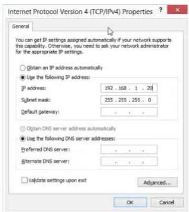
Fig. 15: Windows Internet control panel
Finding and changing the TCP/IP address and the subnet mask on a computer running OS X
▶ Go to System Preferences / Network.
▶ Select "Ethernet".
▶ Under "Configure IPv4", select "Manually".
▶ Set the TCP/IP address.
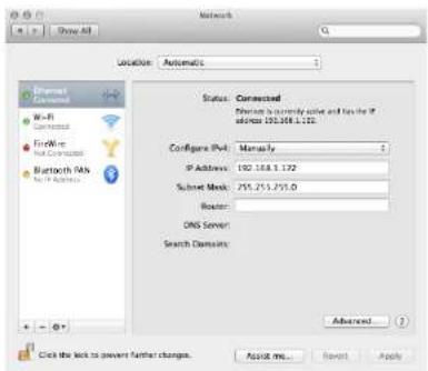
Fig. 16: OS X Network preferences
For further information, please refer to you operating system's integrated help system.
Changing subnet mask and TCP/IP address of a Clarity X
To change the subnet mask and TCP/IP address of a Clarity X, you need to access it using a computer running the TC Icon software. This means that in case of an IP address conflict that keeps you from accessing Clarity X in the first place, you need to change your computer's IP first as described in the previous section.
▶ Launch the TC Icon software on your computer.
▶ Select the particular Clarity X you want to access.
▶ Click on the Frame tab.
▶ Select the System page.
▶ Select the Setup subpage.
▶ Select Net.
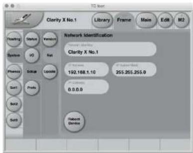
Fig. 17: Network identification page in TC Icon software
Changing the Clarity X IP address
▶ Select the IP address parameter.
▶ Enter the new IP address.
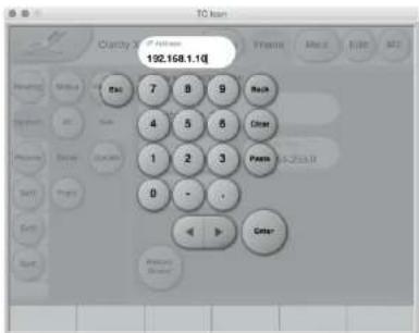
Fig. 18: Entering a new Clarity X IP address
▶ Confirm by clicking Enter.
▶ You will be asked to confirm the new IP address.
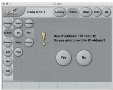
Fig. 19: Confirmation of new Clarity X IP address
▶ Confirm by clicking Enter.
▶ Conform the next dialog to reboot Clarity X with the new IP address.
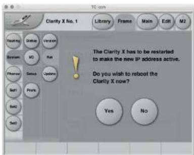
Fig. 20: Confirmation of Clarity X reboot
Changing the Clarity X subnet mask
▶ Select the IP Subnet Mask parameter.
▶ Enter the new subnet mask.
▶ Confirm by clicking Enter.
Resetting the IP address of a Clarity X
You may need to reset the IP address of a Clarity X. This procedure is described in the section "Front panel reset button" on page 32.
If the serial number of a particular Clarity X ends with "00", the default IP address for this device will be 192.168.1.100, as "00" is not a valid IP number in all networks.
There is a small risk that two Clarity X units (or other TC signal processors) on a network have the same last two digits in the serial number and thus will conflict after a reset. To resolve this issue, reset one Clarity X first and change its IP address before connecting the second Clarity X.
Quick Setup
This guide applies for a simple setup as illustrated below.
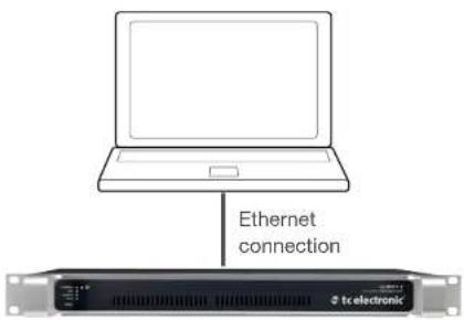
Fig. 21: Connecting Clarity X to a computer via Ethernet
Requirements for this setup are:
▶ A Clarity X
▶ A CAT5 Ethernet cable
▶ A computer equipped with an Ethernet adapter, running Microsoft Windows or Mac OS X and the latest version of TC Icon software.
Proceed as follows:
▶ Unpack Clarity X and install it in a stable, well-ventilated space.
- Connect Clarity X and your computer using an Ethernet cable.
▶ Power up your computer and Clarity X.
▶ If you have not already done so, download and install the latest version of the TC Icon software editor on your computer.
▶ Launch the TC Icon software on your computer.
The following screen will appear:
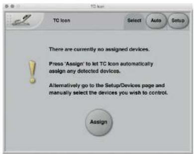
Fig. 22: Assigning Clarity X in TC Icon
Click "Assign".
The network is scanned, and all connected and operational devices will be listed on the next screen.
▶ Select the device you wish to access.
To have TC Icon detect more devices and assign them to one of up to eight slots, see "Assigning devices to the available slots" on page 167.
If you cannot access Clarity X, please refer to "Networking basics and troubleshooting" on page 39.
That's it – you are now ready to configure and operate your Clarity X.
Keeping your Clarity X up-to-date
The latest version of the Clarity X software at the time of production is installed on your Clarity X.
However, from time to time, software updates are made available by TC, containing both bug fixes and new features.
To update the software of your Clarity X, you will need the TC Icon software.
Please download and install the most current version of the TC Icon software from:
tcelectronic.com/support/software/
The TC Icon software is available for
▶ Microsoft Windows and
Mac OS X.
Using TC Icon software, you can access your Clarity X and update its built-in software (the firmware), which is provided as a separate download.
Updating Clarity X firmware is described in "Clarity X firmware update and Device Reset" on page 156.
Basic operation using TC Icon software
Clarity X software version 1.3.00 – Build 3275 – Reference manual (updated 2016-10-18)
TC Icon software – introduction
This section of the manual is a general introduction to operating Clarity X using the TC Icon software.
In the following chapters we assume that you have connected Clarity X and your computer directly or as part of a network as described in "Setting up Clarity X" on page 37.
Several Clarity X and other TC signal processors (e.g. a System 6000 MKII), and computers running the TC Icon software can be connected and operated at the same time as part of a standard Local Area Network (LAN). The TC Icon software is used to detect, configure and operate devices from your computer.
If you encounter communication errors or cannot detect or operate a device properly, please refer to "Networking basics and troubleshooting" on page 39.
Basic TC Icon operation
The TC Icon software interface has been optimized for use in real-time situations in broadcast and post production environments (which usually are very different from standard desktop computing tasks and environments). Accordingly, buttons are very prominent and clearly labelled to ensure proper operation even in stressful situations. In addition, important parameters can be assigned to on-screen faders, allowing for precise control and immediate visual feedback.
The interface can be customized. Customizable parameters include fader positions and user interface colors. For more information, please refer to the chapters "UI (user interface) page" on page 170 and "Color page" on page 171 of this manual.
TC Icon interface: Tabs versus pages
▶ Use the tab buttons on the upper edge of the TC Icon window to select a primary group of functions.
▶ Use the page buttons on the left edge of the TC Icon window to select specific pages.
TC Icon modes: Base and Device operation
The TC Icon software has two operation modes: Base and Device operation.
▶ Use Base mode to select devices and configure the network and the TC Icon software itself.
In Base mode, you will see the Select, Auto and Setup tabs on the upper edge of the TC Icon window. Most Base mode functions are described in the chapter "TC Icon Setup" on page 164.
▶ Use Device operation mode to operate the currently selected device.
In Device Mode, you will see the specific tabs for operating the currently selected TC device.
Switching between Base and Device operation modes
To switch between Base and Device operation modes, click the Icon symbol in the upper left corner of the window.
Fig. 23: Icon symbol
TC Icon faders
The TC Icon software has large on-screen faders. They have several features that will help you operate your Clarity X efficiently.
There are six on-screen faders.
- You can change the position of the faders or hide them completely – see "UI (user interface) page" on page 170.
The name of the parameter that a fader is currently assigned to is displayed above the fader.
When no label is shown above a fader, that fader is currently not assigned to a parameter.
▶ Fader assignments and values will always reflect the current TC Icon page fader assignments and the last adjustments you made.
Using Faders for fine adjustments
When a parameter is assigned to a fader, you can choose between Normal and Fine adjustment mode.
In Normal Adjustment mode, the fader range will cover the full parameter range - e.g. -24 dB to 12 dB for the Source Gain parameter.
In Fine Adjustment mode, the fader range will be smaller, allowing you to fine-tune around the current value – e.g. in 0.1 dB steps for a level parameter.
To switch a fader from Normal Adjustment mode to Fine Adjustment mode or back, click the label above that fader. Fine Adjust mode will be indicated by two triangles in the label field.
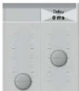
Fig. 24: Fader label (two triangles) indicating Fine adjustment mode for the currently selected parameter (Delay)
TC Icon on-screen keyboard
Clarity X allows you to store and rename presets, assign labels to inputs and outputs and perform other functions where text input is required. When you access one of these functions, an on-screen keyboard will be displayed.
![YG 40cm Clarity & Pro.1 Library Frames Main Edit NJ Enter C:\Users\Normal\Normal\Normal Default[1] 1 2 3 4 5 6 7 8 9 10 11 12 13 14 15 16 17 18 19 20 21 22 23 24 25 26 27 28 29 30 31 32 33 34 35 36 37 38 39 40 Q W E R T Y U I Q P { ! } SVM A S D F G H J K L : ? * Z X C V B N M < > ? Other](/content/2026/05/977920/images/f727d8b9c6c48bc6c232ab3f2328d36f63e0c6c6eac00fcabc0f51e963af1343.jpg)
Fig. 25: TC Icon software – On-screen keyboard
While they keyboard is being displayed, you can either click the letters shown on-screen or use your computer's keyboard for character input. When you are done, click the large Enter button or press your computer keyboard's Enter key.
Accessing Clarity X
Clarity X software version 1.3.00 – Build 3275 – Reference manual (updated 2016-10-18)
tc electronic Accessing Clarity X
- Connect your computer and Clarity X as described in the "Setting up Clarity X" chapter.
▶ Power up your computer and your Clarity X.
▶ On your computer, launch the TC Icon software.
▶ When you do this for the first time or the system configuration has been changed, the following screen will appear:
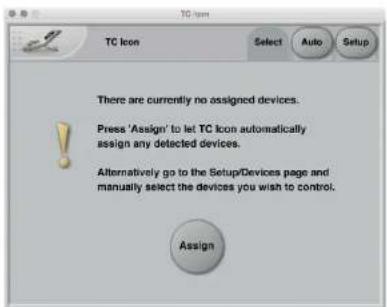
Fig. 26: Assigning Clarity X in TC Icon
Click "Assign".
All currently connected TC signal processors that are supported by the TC Icon software should be detected and assigned to one of the eight on-screen slots/locations.
If a connected device is not detected, please refer to "Networking basics and troubleshooting" on page 39.
▶ Click the icon representing the Clarity X to access it.
Operating multiple computers and/or TC HD devices in one network
In a more complex setup with multiple TC Icon hardware remote controls and/or several networked computers running TC Icon software, each of these TC Icon units and computers can be used to connect to TC HD devices (System 6000 MKII, DB6, Loudness Pilot, UpCon) on this network.
If your setup contains multiple TC HD devices, you should name these devices unambiguously so you don't accidentally edit the settings of the wrong device.
Scanning and rescanning a network for devices
The scenario described above covers the first time you boot up your system or when no connected units are assigned.
When...
▶ you make changes to your setup,
▶ when devices are powered up or down, or
▶ if there are connection errors,
devices may not be detected properly.
In this case, you should scan the network again.
Scanning a network for devices
In the TC Icon software, go to Setup / Devices
▶ Click the Detect button.
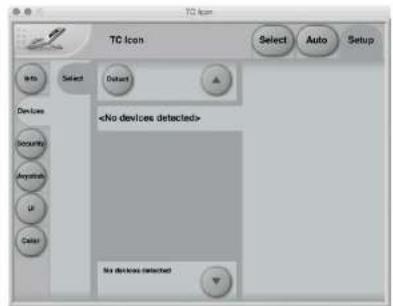
Fig. 27: Setup - No devices detected
For further information, see "Devices page" on page 167.
In the following sections of this manual, we assume that you are operating a basic system with one Clarity X connected.
Obtaining Clarity X status information
Clarity X software version 1.3.00 – Build 3275 – Reference manual (updated 2016-10-18)
Clarity X status page
Please note that the LEDs on the front of a Clarity X will display basic status information as long as the device is powered – see "Front panel indicators" on page 30.
Additional status information can be obtained using TC Icon, where you can also define how certain error states should be indicated on the device.
To display status information about Clarity X, go to Frame / System / Status.
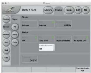
Fig. 28: Clarity X Status page
Clock section
Source indicator
Indicates the source of the clock signal Clarity X is currently following.
Lock indicator
Indicates whether synchronization has been achieved.
If no synchronization has been achieved, a red LED will be shown in the upper right corner of this field, and "Freewheel" will be shown.
Nominal Rate indicator
Shows the detected sample rate of the signal Clarity X is synced to.
For information on clock setup and sample rate ranges, see "Clock Setup" on page 61.
Status section
Running indicator
Displays the current state of the Clarity X power supplies.
The states and color codes shown here are the same as those shown by the Clarity X Running LED on the front panel of the device. See "Running LED" on page 30.
Network indicator
Displays the current state of the Clarity X network connection.
The states and color codes shown here are the same as those shown by the Clarity X Net LED on the front panel of the device. See "Net LED" on page 30.
Remote indicator
Displays the Remote control connection state (connected or not connected).
The states and color codes shown here are the same as those shown by the Clarity X Remote LED on the front panel of the device. See "Remote LED" on page 31.
Sync indicator
Displays the current Clarity X synchronization status.
The states and color codes shown here are the same as those shown by the Clarity X Sync LED on the front panel of the device. See "Sync LED" on page 31.
Frame Identification parameter
If you are operating a complex system with multiple Clarity X units, you may need to identify one specific unit quickly. To do so, select the respective Frame using TC Icon software and then use the Frame Identification parameter to have that Frame identify itself with blinking Alert LEDs as follows:
"Off" setting
This is the default setting.
"Green/Off", "Yellow/Off", "Red/Off", "Green/Yellow", Green/Red", "Yellow/Red" The Alert LED on the front panel of the respective Frame will blink in the chosen color or color combination, while the Alert indicator field will read "LED blinking".
Temperature indicator
The Temperature Indicator shows the current internal temperature of Clarity X
▶ in degrees Celsius when Dimension Unit on the Preferences page is set to Metric.
▶ in degrees Fahrenheit when Dimension Unit on the Preferences page is set to Feet.
For more information, see "Preferences" on page 152.
Setting up audio and syncing
Clarity X software version 1.3.00 – Build 3275 – Reference manual (updated 2016-10-18)
Setting up audio and syncing – introduction
Configuring Clarity X as the heart of your studio speaker setup and signal flow properly has three main aspects:
▶ Defining the signal routing for inputs and outputs. Use the Frame / Routing page to configure inputs and outputs.
For more information, see "Signal routing" on page 59.
▶ Defining basic digital audio parameters. Use the Frame / System / IO page to configure digital audio parameters such as clock master and synchronization source.
For more information, see "Clock Setup" on page 61.
▶ Defining the physical setup of your studio speakers and related sound processing parameters such as bass management.
For more information on configuring your speakers using Clarity X, see "Speaker Set configuration" on page 66.
For basic information about setting up speakers, room acoustics, reflection, absorption and related topics, see "Appendix 2: Acoustics" on page 175.
Signal routing
The Frame / Routing page allows you to see and edit the assignments of the physical inputs and outputs of Clarity X to the Source ("Src") and Speaker Set modules.
For a general signal flow overview, see "Clarity X signal flow diagram" on page 26.
For a list of inputs and output, see "Clarity X status indicators and ports" on page 29.
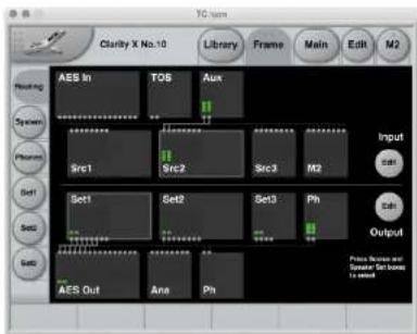
Fig. 29: Frame / Routing page
The routing page displays the signal flow through Clarity X from top to bottom, with the physical inputs shown on top and the outputs at the bottom. When a valid signal is present at an input, the small meters in the respective input and signal processing modules will display it.
Editing input routings
To assign a physical input to a Source Module, proceed as follows:
▶ Click the Edit button under Input so it is highlighted.
▶ Click a Source Module to select it (e.g. "Src 3").
▶ Use Fader 2 to select a channel in the selected Source Module (e.g. "Src3 C" (Source 3, Center Channel).
▶ Use Fader 1 to assign an Input Module and a channel in that Input Module to the previously selected Source Module channel – e.g. "AES In 3" (AES Input, Channel 3).
The currently selected Input Module, signal channel and Source Module will be highlighted.
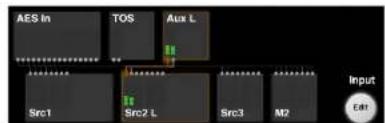
Fig. 30: Routing an input channel to a Source Module channel
Editing output routings
To assign a Speaker Set Module to a physical output, proceed as follows:
▶ Click the Edit button under Output so it is highlighted.
- Click a Speaker Set Module to select it (e.g. "Set2").
▶ Use Fader 5 to select a channel in the selected Speaker Set Module (e.g. "Set2R" (Set 2, Right Channel).
▶ Use Fader 6 to assign an Output Module and a channel in that Output Module to the previously selected Speaker Set channel – e.g. "AES Out 2" (AES Output, Channel 2).
The currently selected Speaker Set Module, signal channel and Output Module will be highlighted.
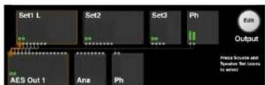
Fig. 31: Routing a Speaker Set channel to a physical output channel
Notes about input and output routing
- Clicking a Source Module on the Routing page will select this Source Module. This allows you to easily switch and check inputs without returning to the Main page.
▶ You can activate both Input and Output editing at the same time.
▶ You can route one input signal to multiple Source modules.
▶ You can route signals from multiple Speaker Sets to the same physical output. This allows you to create “virtual Speaker Sets” – i.e., configurations with specific settings that repurpose your physical monitors, e.g. by defining a Stereo Setup with a custom EQ curve that reuses the left and right speaker of your 5.1 setup.
▶ Please note that when Studio Setup editing has been disabled on the Frame / Systems / Setup page, the Output Edit button will be replaced by a Show button, and you will only be able to select and display output routings, but not change them. For more information, see "Studio Setup Enable button" on page 155.
Clock Setup
To set up audio, go to Frame / System / I/O / Clock.
Use this page to...
▶ display information about the status of the incoming digital audio signal,
configure synchronization setup parameters.
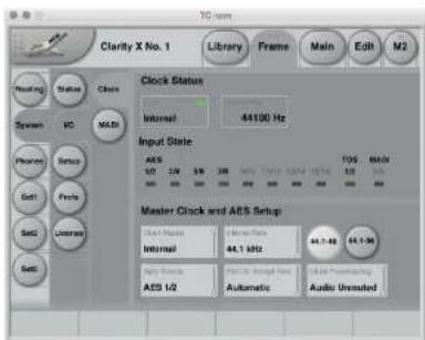
Fig. 32: I/O setup - Clock page
Clock Status section
Lock status indicator
Lock status states: Lock, No lock, Freewheel, Internal, Bypassed
The Lock status indicator shows the overall reference clock status. The colors of the "LED" in this field represent the Icon application warning/error scheme, which is used for alarms on e.g. Icon, the Clarity X front UI, GPO and SNMP.
"Lock" (green LED / OK)
Clarity X has obtained lock to the reference signal set in the Sync Source field.
"No Lock" (red LED / Error)
"No Lock" is typically displayed when there is no signal present on the Input that Clarity X is set to lock to, or if the incoming sample rate is outside the legal range (48 kHz +1.7 % / -1.3 %) and the Clock Fallback parameter is set to Halt.
"Freewheel" (red LED / Error)
"Freewheel" is displayed when there is no signal present on the Input that Clarity X is set to lock to, or if the incoming sample rate is outside the legal range (48 kHz +1.7 % / -1.3 %) and the Clock Fallback is set to Freewheel.
"Internal" (yellow LED / Warning)
"Internal" is displayed when Clarity X is set to sync to its internal referenced master clock at 48.000 kHz.
"Bypassed" (yellow LED / Warning)
"Bypassed" is displayed when the Clarity X hardware bypass relay has been activated.
Sample Rate indicator
The Sample Rate indicator field displays the sample rate of the sync source Clarity X is currently following. Sample rate is measured and displayed with 1 Hz precision (21 PPM @ 48 kHz).
Input State indicators (AES, TOS, MADI)
The Input State indicator labels and LEDs show the status of the various inputs. States are displayed as follows:
Green LED
A green "LED" indicates that a signal is present and synchronous at the respective input.
Yellow LED
A yellow "LED" indicates that a signal is present and running asynchronously relative to the sync source. This typically happens when the upstream device is running at an internal master clock rate and is not locked to the house clock.
Grey LED
A grey "LED" indicates that no signal is present at the respective input or that the incoming sample rate is outside the legal range (48 kHz ±0.38 %).
N/A label (MADI)
Without the MADI option installed, the Input State for MADI will be N/A (not available) with a gray LED.
56 or 64 label (MADI)
This is the number of available channels in 44.1 to 48 kHz for the incoming MADI stream.
28 or 32 label (MADI)
This is the number of available channels in 96 kHz for the incoming MADI stream.
Green LED (MADI)
Input is in sync.
Yellow LED (MADI)
Sample slip/repeats have been detected on the MADI input.
Master Clock and AES Setup section
All preselection settings made in this section are stored as part of Routing (and Project) presets together with the Clarity X input routing.
For more information on storing data in Clarity X, see "The Library: Recalling, storing and deleting settings" on page 91.
Clock Master parameter
Settings: External (default), Internal
Use the Clock Master parameter to set whether Clarity X should be referencing an incoming external clock source or an internal crystal running at 44.1 kHz or 48 kHz.
▶ External reference is mandatory in a broadcast installation and therefore the default setting.
▶ Internal reference is typically only for test use, or when working with analog signal sources only.
Internal Rate parameter
Settings: 44,1 kHz, 48 kHz, 96 kHz*
If you have set the Clock Master parameter to Internal, you can use the Internal Rate parameter to set the internal clock rate of Clarity X.
* The 96 kHz option is only available when you have selected the 44.1-96 Sample range button.
Sample rate range buttons (44.1-48 and 44.1-96)
Click a button to select the sample rate range that Clarity X will accept: 44.1 to 48 kHz or 44.1 to 96 kHz.
Notes about working with 96 kHz
Please note that running your system at 96kHz introduces some limitations. Accordingly, if you do not intend to run your system at 96kHz , or if you work with film 7.1, you can select the 44.1-48 range, which ensures that the full Clarity X feature set will be available to you at all times.
If you sometimes or primarily run 96 kHz, you may wish to have a constant feature set available for all sample rates. In this case, you should select the 44.1-96 range.
If you select the 44.1-96 kHz range, set the Clock Master parameter to "External" and set the External Clock Accept Rate parameter to "Automatic". These settings ensure that Clarity X will automatically follow the incoming sample rate at 44.1, 48 or 96 kHz. This may be convenient in a studio setup where the audio host program is determining the sample rate. If you set the Clock Freewheeling to "Audio Muted", you will may stabilize the total system sample rate shift behavior even further. For more information, see "Clock Freewheeling parameter" on page 63.
Sync Source parameter
Settings: AES 1/2, AES 3/4, AES 5/6,
AES 7/8, AES 9/10, AES 11/12, AES
13/14, AES 15/16, TOS 1/2, MADI
Use the Sync Source parameter to select the external signal source that Clarity X should sync to.
When the Clock Master parameter is set to "Internal", the Sync Source setting is irrelevant. However, you should be aware that you can use this parameter to preselect a sync source that will be used when you switch Clarity X AES directly from Internal to External Sync.
External Clock Accept rate parameter
Settings: 48 Only, 44.1 Only, Automatic
When you have set the Clock Master parameter to External, you can use the External Clock Accept rate parameter to select the sampling rate(s) Clarity X will accept from the external sync source.
When selecting one of the “Only” rates, Clarity X will spend less time on judging if the incoming rate is valid. Accordingly, lock-up time may be shorter.
These “Only” settings can also minimize the general disturbances (during lock-up) on the digital outputs of Clarity X. This is beneficial if speakers are being fed from Clarity X’s digital outputs. These settings may also be beneficial when used in a critical live setup to ensure that downstream disturbances are minimized.
48 Only setting
Clarity X will only lock to incoming signals running at 48 kHz. This may be a good choice when used in a broadcast setup where everything is running synchronously at 48 kHz.
44.1 Only setting
Clarity X will only lock to incoming signals running at 44.1 kHz.
96 Only setting
Clarity X will only lock to incoming signals running at 96 kHz.
Automatic setting
Clarity X will automatically lock to incoming signals running at either 44.1 or 48 kHz. This setting is convenient if you work with projects with different sample rates in a typical post-production studio setup. Combined with the Clock Free-wheeling parameter set to Audio Muted, this configuration is very flexible, while the risk of audio glitches in the studio reaching the speakers during sample rate changes is minimal.
In Automatic mode, obtaining lock to a digital reference signal may take Clarity X a little longer.
Clock Freewheeling parameter
Settings: Audio Unmuted, Audio Muted
Use the Clock Freewheeling parameter to specify how Clarity X should behave when the no external sync source is present.
Clarity X is the last element in the signal chain before your speakers. This is why we put a lot of effort into ensuring consistency and reliability on
the digital outputs, which can be trickier to handle than analog outputs. The Clock Freewheeling technology is part of these efforts.
When sync is lost, Clarity X will continue running on the "last good rate". If possible, Clarity X will run on a 96 bit-precision version of the last good sample rate that the device received. This will only generate few potential sample slips downstream and on the inputs (which may still receive audio), so the audio quality is not significantly reduced.
However, in some borderline cases it may not be possible to calculate the last good incoming sample rate. In such a situation, Clarity X will revert to the internal 48 kHz clock, and audio will still be sent through. Expect more sample slips in such a situation.
Audio Unmuted setting
When sync is lost and the Clock Freewheeling parameter is set to Audio Unmuted, Clarity X will continue running on the "last good rate" as described in the previous paragraph.
Use this setting if you work in a live situation and would rather accept a compromised audio signal when sync is lost (with sample slips in the audio stream) than having no signal at all.
Audio Muted Setting
When the sync source is not present and the Clock Freewheeling parameter is set to Audio Muted, all AES outputs are turned off – meaning no audio data and no AES carrier (no clock) are being sent out.
Use this setting if you prefer to stop audio and clock output completely in a reference sync error situation. In this situation, the input signals are also turned off, and accordingly, meter activity will cease.
With both settings, Clarity X will revert to the reference input signal (as set with the Sync source parameter) once it becomes available again. The changeover will be handled as smoothly as possible on both audio and clock.
MADI setup
Use the MADI page to monitor and configure MADI-related parameters. These options are only available when the optional MADI card is installed.
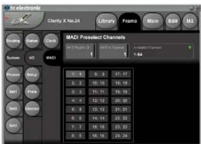
Fig. 33: I/O Setup - MADI page
MADI Preselect Channels section
The main function of this page is to allow you a preselection of 24 channels which are made available on the Routing page. All of the incoming MADI channels can be routed to all of the 24 Router channels.
MADI Router Ch. parameter
Use this parameter to select one of the 24 audio channels that are presented on the Routing page.
MADI In Channel parameter
Use this parameter to select the incoming MADI channel that should be assigned to the respective Clarity X Routing channel. Depending on the incoming format and sample rate, you can make a selection from 28, 32, 56 or 64 channels.
MADI - Available Channels display
Available MADI channels are displayed here as follows:
▶ 1-56: 56 channel format 44.1 or 48 kHz MADI received
▶ 1-64: 64 channel format 44.1 or 48 kHz MADI received
▶ 1-28: 28 channel format 96 kHz MADI received
▶ 1-32: 32 channel format 96 kHz MADI received
▶ No license available: No MADI license installed. Contact TC Electronic support for license purchase. The Clarity X MADI hardware is installed.
▶ No card installed: No MADI hardware card installed. Contact TC Electronic support for an upgrade. See "Getting support" on page 9.
MADI - Available Channels LED
Input state is displayed as follows:
Red: no input
Yellow: slip/repeats
Green: signal in sync
▶ "N/A" and red LED: no MADI input
Speaker Set configuration
To define and use Speaker Sets, you need to activate Studio Setup on the Preferences page.
For more information, see "Studio Setup Enable button" on page 155.
Once you have activated Studio Setup, you can select a Speaker Set by clicking the respective button ("Set1" to "Set3") and define its settings as described in the following section of the manual.
Configuration page
Use the configuration page to define and name a Speaker Set.
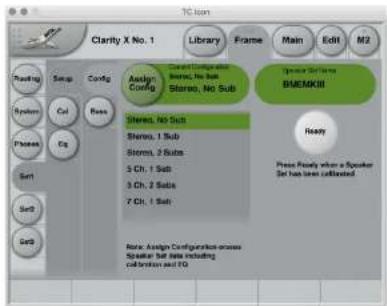
Fig. 34: Speaker Set Configuration page for Speaker Setup 1
Configuring a speaker set
▶ Select the Speaker Set you want to define using one of the three Set buttons on the left side of the screen (Set1, Set2, Set3).
▶ Go to Setup / Config.
▶ Select the correct configuration from the list.
Available settings for Sets 1 and 2 are:
▶ Stereo, No Sub
Stereo, 1 Sub
Stereo, 2 Subs
5 Channels, 1 Sub
5 Channels, 2 Subs
7 Channels, 1 Sub
Available settings for Set 3 are:
Stereo, No Sub
Stereo, 1 Sub
Stereo, 2 Subs
▶ Click the Assign Config Button.
! Assigning a configuration will erase all previously set Speaker Set data, including speaker calibration and equalizer settings.
Ready button
When you have calibrated a Speaker Set, click the Ready button.
Defining a Speaker Setup as “ready” by clicking the Ready button means that you consider the setup as reliable with regards to reference level, speaker parameters etc. This affects parameters and core functions such as Dose Metering. Dose Metering is only possible when a Speaker Set is known to be properly calibrated.
For more information, see "Speaker Set calibration" on page 78 and "Dose Metering" on page 119.
Bass Management page
Bass management is a very important and useful tool – and it is in general an absolute necessity if you want to work with a five channel setup in a small room. The bass management system is designed to reproduce the bass contents from all main channels using a subwoofer.
Clarity X provides several bass management modes.
Please note that bass management is only available when you have configured a Speaker Setup including one or more subwoofers.
For more information about bass management, see "Bass management" on page 188.
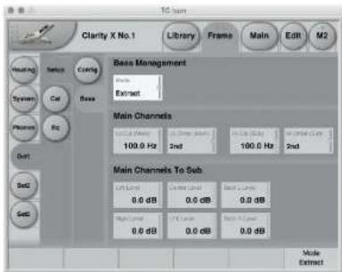
Fig. 35: Bass Management page, Bass Management set to Extract
Bass Management section
Mode parameter
The setting of the Bass Management Mode parameter affect the other parameters on this page.
! Please note that the parameters in the Main Channels section as described in the following section will change based on the selected Bass Management Mode.
Off setting
To deactivate Bass Management, set the Bass Management Mode parameter to Off. Setting Bass Management Mode to Off will disable all other parameters on this page.
Extract setting
To extract the bass signal from the incoming main channels to the output subwoofer channel, set the Bass Management Mode parameter to Extract.
When to use Extract Mode
A typical application for Extract Mode would be playback over main speakers that are too small to reproduce bass signals adequately. In this case, you can use Extract Mode to feed a dedicated subwoofer.
Distribute setting
To distribute the incoming LFE signal to the output main channels and sub channel, set the Bass Management Mode parameter to Distribute.
For more information about the LFE channel, see "The LFE Channel" on page 189.
When to use Distribute Mode
You might want to use Distribute Mode if your main speakers are big enough to play back sub bass signals, and you don't have a dedicated subwoofer in this setup.
Audio formats and bass management modes – overview
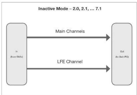
flowchart
graph LR
    A["Input (from RMix)"] -->|Main Channels| B["Output (to Gain/FC)"]
    B -->|LFE Channel| A
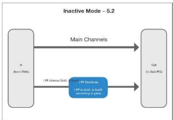
flowchart
graph LR
    A["In (from DMIs)"] -->|Main Channels| B["Out (to Beta/FC)"]
    A -->|LFF channel SubL & SubR\nLFF Distribute\nLFF to SubL & SubR according to gene| B
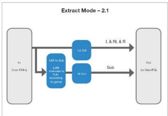
flowchart
graph LR
    A["Input (from DMs)"] --> B["Lr to Sub"]
    A --> C["Lr and sub to Sub according to game"]
    B --> D["Lo Out"]
    C --> E["H & G"]
    D --> F["L & RL & R"]
    E --> G["Sub"]
    F --> H["Output (to ChainFG)"]
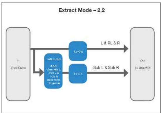
flowchart
graph LR
    A["In (from DMAs)"] --> B["1AR to Sub, 0.4R from Sub L & Sub R according to gene"]
    B --> C["Lo Cut"]
    B --> D["Hi Cut"]
    C --> E["L & RL & R"]
    D --> F["Sub L & Sub R"]
    E --> G["Out (to Output/FOF)"]
    F --> G
Fig. 36: Audio formats and Bass Management modes – overview
Multi-channel downmix - overview ctc.
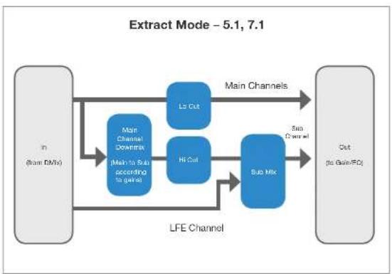
flowchart
graph TD
    A["In (from RMix)"] --> B["Main Channel Domin Mix"]
    A --> C["Main to Sub according to gain"]
    B --> D["LS Cut"]
    B --> E["Hi Cut"]
    C --> F["Sub Mix"]
    D --> G["Out (to Gain/BO)"]
    E --> G
    F --> G
    G --> H["Main Channels"]
    H --> I["Sub Channel"]
    I --> J["Out"]
    style A fill:#f9f,stroke:#333
    style I fill:#ccf,stroke:#333
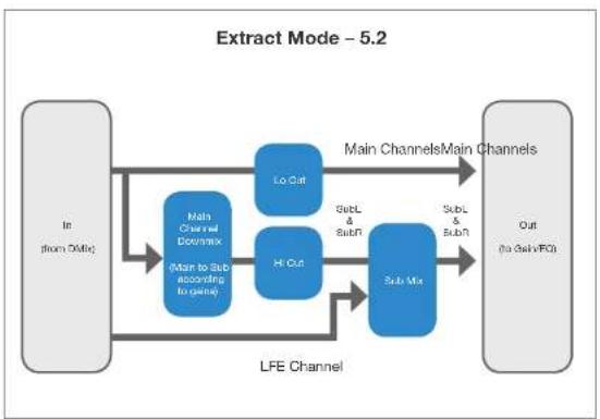
flowchart
graph TD
    A["In (from DMix)"] --> B["Main Channel Doenmax\n(Main to Sub according to gena)"]
    B --> C["Lo Cut"]
    B --> D["Hi Cut"]
    C --> E["Sub Mix"]
    D --> E
    E --> F["Out (to DelivFO)"]
    G["LFE Channel"] --> B
    G --> D
    H["Sub & SubR"] --> E
    I["SubL & SubR"] --> E
    J["Main Channels/Main Channels"] --> E
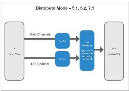
flowchart
graph LR
    A["Lo (from DMIs)"] -->|Main Channels| B["Lo Out"]
    A -->|Main Channels| C["Hi Out"]
    B --> D["LFE Distribute (Mix LFE to all channels according to genre)"]
    C --> D
    D --> E["Out (to DAiveEQ)"]
Fig. 37: Audio formats and Bass Management modes – overview ctd.
tc electronic Setting up audio and syncing
Main Channels section (Bass Mode set to "Off")
With Bass Mode set to Off, this section is disabled.
Levels section (Bass Mode set to "Off")
With Bass Mode set to Off, this section is disabled.
Main Channels section (Bass Mode set to "Extract")
Lo Cut (Main) parameter
Use the Lo Cut (Main) parameter to set the frequency for the low cut filter that will be applied to the main channels when Bass Management is active.
Lo Order (Main) parameter
Use the Lo Order (Main) parameter to set the slope for the low cut filter that will be applied to the main output channels when Bass Management is active.
Hi Cut (Sub) parameter
Use the Hi Cut (Sub) parameter to set the frequency for the high cut filter that will be applied to the subwoofer channel when Bass Management is active.
Hi Order (Sub) parameter
Use the Hi Order (Sub) parameter to set the slope for the high cut filter that will be applied to the subwoofer when Bass Management is active.
Main Channels to Sub section (Bass Mode set to "Extract")
For a 5.1 speaker configuration, this section contains the following parameters: Left / Right / Center / LFE / Back L / Back R Level.
For a 7.1 speaker configuration, this section contains the following parameters: Left / Right / Center / LFE / Back L / Back R / Side L / side R Level.
For more information, see "Configuration page" on page 66.
Use these parameters to define the signal amount that should be routed from the respective 5.1 or 7.1 signal component to the subwoofer(s) in this Speaker Set.
Main Channels section (Bass Mode set to "Distribute")
Lo Cut (Main) parameter
Use the Lo Cut (Main) parameter to set the frequency for the low cut filter that will be applied to the main channels when Bass Management is active.
Lo Order (Main) parameter
Use the Lo Order (Main) parameter to set the slope for the low cut filter that will be applied to the main output channels when Bass Management is active.
LFE section (Bass Mode set to "Distribute")
Hi Cut parameter
Use the Hi Cut (Sub) parameter to set the frequency for the high cut filter that will be applied to the incoming LFE channel before it is distributed to the main channels when Bass Management is active.
Hi Order (Sub) parameter
Use the Hi Order (Sub) parameter to set the slope for the high cut filter that will be applied to the incoming LFE channel before it is distributed to the main channels when Bass Management is active.
LFE to Main Channels section (Bass Mode set to "Distribute")
For a 5.1 speaker configuration, this section contains the following parameters: Left / Right / Center / LFE / Back L / Back R Level.
For a 7.1 speaker configuration, this section contains the following parameters: Left / Right / Center / LFE / Back L / Back R / Side L / side R Level.
For more information, see "Configuration page" on page 66.
Use these parameters to define the signal amount that should be routed from the source signal's LFE channel to the respective speakers in the 5.1 or 7.1 Speaker Set.
For more information about the LFE channel, see "The LFE Channel" on page 189.
EQ page
Use the EQ page to set equalization for each speaker in the current Speaker Set.
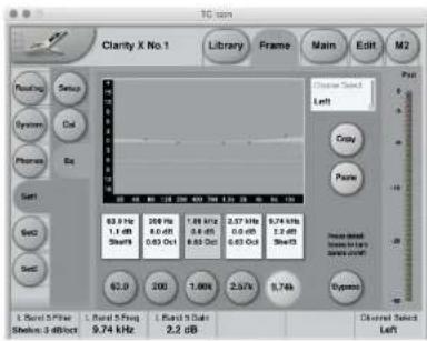
Fig. 38: EQ page with Band 3 deactivated and Band 5 selected for editing
Channel Selection
Channel Select parameter
Use the Channel Select parameter to select a channel for equalization. The number of channels depends on the speaker configuration you have set on the Configuration page.
For more information, see "Configuration page" on page 66.
The EQ encompasses five frequency bands for each channel.
Using the Equalizer
Activating or deactivating a frequency band
To activate/enable a frequency band, click the rectangular Details field for this band.
An active frequency band is represented by a white box, an inactive band is shown as a gray box.
Editing the settings of a frequency band
To edit the settings of a frequency band, click the round button showing that frequency band's frequency.
The frequency band parameters will be mapped to Faders 1, 2 and 3 for editing.
Copying EQ band settings from one channel to another
To copy the EQ settings (type, frequency, gain, off/on status for all EQ bands) from one speaker to another speaker,
▶ use the Channel Select parameter to select the speaker with the settings you want to copy,
▶ press the Copy button
▶ select the target speaker,
▶ press the Paste button.
! You can also copy EQ band settings from a speaker in one Speaker Setup to a speaker in another Speaker Setup.
Bypassing the equalizer
To bypass the equalizer for the currently selected speaker, press the Bypass button in the lower right corner of the EQ page.
Frequency band parameters
The following parameters are available for editing when a frequency band has been selected.
Filter type parameter
Use this parameter to set the filter type.
For frequency bands 2, 3 and 4, select a Parametric Band with a bandwidth slope between 0.1 Octave and 4 Octaves.
For frequency bands 1 and 5, you can also choose between a Shelving type (3 to 6 dB/Octave) and Cut filters (Bessel and Butterworth types)
Filter frequency parameter
Use this parameter to set the filter frequency.
Filter frequency gain parameter
Use this parameter to set the filter frequency.
Phones setup
Use the parameters on the Frame / Phones page to configure the Headphones output (labeled "Phones") on the back of your Clarity X correctly for the connected headphone set.
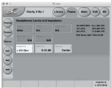
Fig. 39: Frame / Phones page
For more information about using a headphone set with Clarity X, see "PHONES - Headphone connector" on page 34.
Headphones Levels and Impedance section
An introduction to headphone calibration
As a Clarity X user, you know that calibrated listening is extremely important for a lot of reasons. This doesn't change when working with headphones. Accordingly, headphones have to be calibrated as well to ensure reliable results.
Obviously, headphones cannot be calibrated using a microphone. This is why we have come up with a different approach.
TC has analyzed the most commonly-used headphones in pro audio and created pre-calibrated presets for them. Use the presets available from the Frames / Phones page to ensure you can enjoy a calibrated listening experience no matter whether you are using monitors or headphones. Simply select the vendor and model of your headphones.
Once you have set the headphones vendor and model, you can enjoy equal SPL levels when you switch between your calibrated speakers and headphones, making it easy to compare your mix between speakers and headphones – just as you would do when switching between two sets of calibrated speakers.
If your headphone set of choice is not part of the Clarity X headphones database, you can enter the relevant parameters yourself. Clarity X can handle calibration of any headphone set from 6-800 Ohm. This technology is called Variable Impedance Drive (VZD). It is capable of handling the a factor of more than 70x between the lowest and highest headphones impedance.
Vendor parameter
Use the Vendor parameter to select the Vendor of the currently used headphones. This will populate the Model parameter with all calibrated models.
Model parameter
Use the Model parameter to select the currently used headphone model.
Only models from the vendor you have selected with the Vendor parameter that have been calibrated by TC are available. If your particular headphone set is not available, please set the Vendor to "Other" and enter the relevant parameters yourself.
The three following parameters are only applicable for redefined headphone presets from the internal Clarity X database.
Impedance display/parameter (top)
The top Impedance display/parameter on the Frames / Phones page will show the impedance for the currently selected headphones preset.
▶ If the selected model only has one impedance setting, this parameter cannot be changed.
▶ If the selected model comes in different impedance variants (such as the Beyerdynamic DT990), you can use the parameter to select the correct impedance.
Gain Trim parameter
Setting: -6 to 1.5 dB
Use the Gain Trim parameter to trim the headphone signal gain for the currently selected headphones preset. This setting is taken into account for Dose calculation.
Balance parameter (top)
Setting: -6 dB Left to -6 dB Right
Use the upper Balance parameter to adjust the Stereo balance for the currently selected headphones preset.
The three following parameters are only applicable when the Vendor parameter has been set to "Other", i.e. when you are configuring headphones that are not defined in the internal Clarity X database.
Impedance parameter
Settings: >275 Ohm, 50-300 Ohm, 25-100 Ohm, 8-50 Ohm
Use the Gain parameter to adjust the headphone impedance if you have set the Vendor parameter to "Other", i.e., if you are adjusting the impedance setting for headphones that are not part of the Clarity X database.
Gain parameter
Setting: -30 to 0 dB
Use the Gain parameter to adjust the headphone signal gain if you have set the Vendor parameter to "Other", i.e., if you are adjusting the gain setting for headphones that are not part of the Clarity X database.
Balance parameter (bottom)
Range: 6 dB L to 0.1 L, Center, 0.1 R to 6 dB R Use the lower Balance parameter to adjust the Stereo balance if you have set the Vendor parameter to "Other", i.e., if you are adjusting the balance setting for headphones that are not part of the Clarity X database.
Speaker Set calibration
Clarity X software version 1.3.00 – Build 3275 – Reference manual (updated 2016-10-18)
Speaker Set calibration – introduction
Why is calibrated listening important?
Calibrated listening is fundamental, giving you many crucial benefits. Most of them have to do with consistency, which is absolutely essential when it comes to delivering great-sounding mixes. Your aim should be to ensure that your mix will sound great not just in this room on these speakers for this particular format – but every time, for any delivery format.
Making sure that you mix at the same SPL level in every session on every day is essential because you are likely to mix quite differently at different SPL levels. If you calibrate your system, you simply will be able to achieve more consistent mixes.
For example, as you can see from the frequency charts below, if you mix at a 60 dB SPL, there is a level difference of 26 dB between 100 Hz and 1 kHz. But when you are mixing at 80 dB SPL, the difference is only 18 dB.
Accordingly, if you mix at 60 dB SPL one day and above 80 the next, your mixing decisions will probably not be consistent even if the content is similar or even identical.
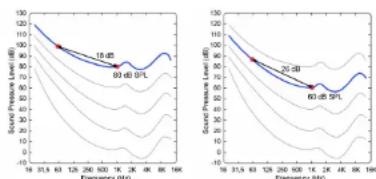
Fig. 40: Level differences when mixing at different sound pressure levels
Calibrated listening ensures...
▶ Consistency between rooms: Create the same reference level across different mixing studios and editing suites.
▶ Consistency between sessions: Ensure the same reference level every day of the week.
▶ Consistency between Speaker Sets: Mix at the same reference level when you switch between Speaker Setups and audio formats.
In this chapter, you will learn how to calibrate your Speaker Setups properly.
Setting up the 3600A Reference Microphone for speaker system calibration
Clarity X comes with a factory-calibrated reference microphone dedicated for speaker system calibration and measurements.
The 3600A Reference Microphone has omni characteristics. It is optimized and DSP-compensated for random incident, making Clarity X ideal for room measurements.
Set up the microphone pointing upwards to ensure an identical angle towards all speakers in your setup. This minimizes measurement uncertainties.
Calibration
The microphone is calibrated at the factory with 94 dB SPL, and the resulting output voltage - e.g. -42.7 dBV - is noted on the calibration label on the microphone along with the date of calibration. To ensure that Clarity X measurements have the highest maximum precision, this calibration value must be entered using the Icon application on the Frame - System - Prefs page.
For more information about pairing and aligning Clarity X and microphones in case of replacement, see "Microphone calibration level display" on page 155
Calibrating a Speaker Set – Basic Steps
Calibrating a speaker set involves the following steps:
- Make all audio connections, including the Reference Microphone.
- Make sure that the Speaker Setup you want to calibrate and the physical outputs of Clarity X are connected correctly on the Routing page. For more information, see "Signal routing" on page 59.
- Make sure you have selected the correct Speaker Setup (using either the Monitor Output buttons on the Main page, the Speaker Set parameter on the Main Edit page or the Remote Control).
- Make sure you have selected the correct Speaker Set Configuration on the respective Speaker Set's Setup / Config page
- Position the Reference Microphone at your listening position. The microphone is omnidirectional and should point upwards to ensure optimum results.
- Go to the Cal subpage for the currently selected Speaker Set.
From here, you can choose between Wizard-based or manual calibration (see "Manual Speaker Set Calibration – Step by Step" on page 85.
Using the Wizard for Speaker Set calibration
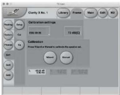
Fig. 41: The Calibration page with the Wizard and Manual buttons
The Calibration Wizard significantly lowers the time required for calibrating your Speaker Set(s) properly, guiding you through the process.
Alternatively, you may want to calibrate your Speaker Sets manually, giving you fine-grained control of all relevant information – see "Manual Speaker Set Calibration – Step by Step" on page 85.
You can cancel the Calibration procedure at any point by clicking the Abort button on a subpage. This will leave the previous settings for this Speaker Set intact.
Speaker Set calibration using the Wizard – step by step
- Press the Wizard button to start the process.
- On the next page, choose...
▶ a calibration standard using the Calibration Method parameter)
▶ the target level using the Acoustical Level parameter
▶ a sweet spot (you can define and calibrate up to four sweet spots).
! Please note that a sweet spot is a physical location in the studio, which should be defined and used independently of the Speaker Set currently used.
- Click the Next button.
- To proceed with Calibration, click the Cal button and leave the listening position, where the Reference Microphone is positioned.
Calibration Process and Scope
Please note that when using the Calibration Wizard, measurements will include latency introduced both by the amplifier and the distance to the speaker. In other words: The calibration process will compensate any delay resulting from the amplifier or the speaker position.
The calibration process starts out at a low level and increases until the target level is reached. This process takes around 45 seconds for each speaker in the setup. This way, Clarity X can adapt perfectly to different amps and speakers with high precision while ensuring that neither your ears nor the speaker system are damaged during the process.
During calibration, both the distance from each speaker to the microphone and the signal phase will be measured. The absolute signal phase will also be measured for main channels speakers, but not for subwoofers.
After the Calibration Wizard has measured distances, the required compensation delay will automatically be calculated for each main speaker, but not for the subwoofer(s).
Compensation delay for subwoofers
Tests have shown that compensation delay for subwoofers has no effect. Accordingly, a Delay setting for the subwoofer(s) – whether set by the Calibration Wizard or manually using the Delay parameter – can usually be discarded, i.e. reset to zero.
However, setting the Phase parameter for the subwoofer(s) is important. This parameter is currently not set automatically because it relates to your bass management choice.
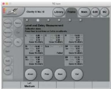
Fig. 42: Calibration page – Level and Delay measurements results sub-page
- Click the Next button to display the next sub-page, allowing you to calibrate your subwoofer(s) using multiple measurements.
Multi Point Sub Calibration
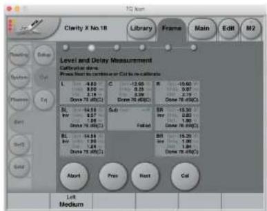
Fig. 43: Multi Point Sub Calibration
Room modes may result in measurement fluctuations near to the physical sweet spot. For more information, see "Room modes" on page 182.
To compensate for such fluctuations, the Calibration Wizard allows you to make three additional measurements near the chosen sweet spot. The measurements are then averaged, giving a more reliable result.
-
Place the microphone near the sweet spot and click the Cal button. You will then be prompted to repeat the measurement after moving the microphone about 30 cm (1 foot) away from the sweet spot.
-
After making these additional measurements, click the Next button to display the next sub-page, showing the Phase Check Results.
Reading the Phase Check Results page and fixing Phase Inversion issues
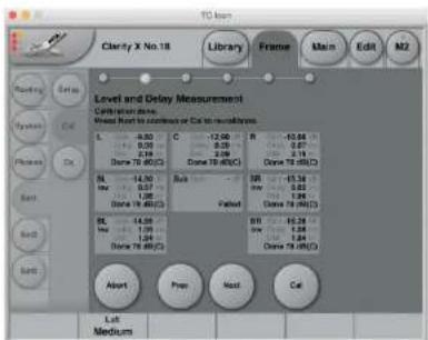
Fig. 44: Calibration page – Phase Check Results sub-page
After calibration, the Phase Check Results page will display the Phase Check status for each speaker with a small "LED" above the respective Speaker's Inv(ert) button. Read these LEDs as follows:
▶ Green LED: This speaker channel has been found to be in phase and OK.
▶ Yellow LED: this speaker channel has been identified as being phase-inverted. To solve this issue, you can either click the Inv button for this speaker to invert the signal phase in Clarity X, or you can rewire the speaker, i.e. exchange the positive and negative terminal wires.
- Grey LED: The calibration has failed for that specific channel – usually this means that the
respective speaker has not been connected, or there may have been a problem with the microphone.
! Please note that the Subwoofer Phase is reset to 0°, as shown here, it cannot be changed as part of the Wizard calibration process. Adjust it after running the Wizard as described in "Post-calibration optimization" on page 84.
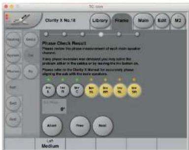
Fig. 45: Phase Check Results sub-page with four speaker channels inverted (yellow buttons) after phase inversion has been detected (yellow LEDs)
- Click the Next button to display the next sub-page, allowing you to define the Speaker sizes.
Speaker Size Selection
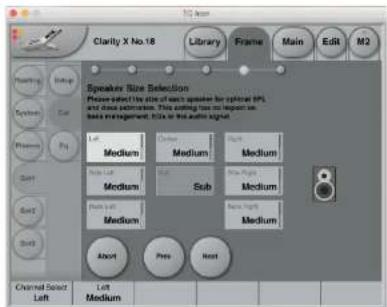
Fig. 46: Speaker Size Selection sub-page
After letting the wizard calibrate the Speakers, you can use the Speaker Size Selection subpage to set the size for each speaker (which cannot be detected automatically). Defining speaker sizes ensures optimal SPL and dose estimation results. Please note that the settings made on this page have no effects on bass management, EQs or the actual audio signal.
- Click the Next button to display the next sub-page, showing the calibration results.
Calibration Results Page
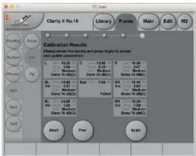
Fig. 47: Calibration Results Page
On the final Calibration wizard sub-page, you can review and apply the calibration settings.
For each speaker, Gain settings, Delay, Size, Acoustical Level and Phase Inversion (if applicable) are shown.
Once you click Apply, the Ready button or the respective Speaker Set and the chosen sweet spot are enabled on the Setup / Config page. You can now use the Speaker Set and rely on SPL and dose estimations.
Post-calibration optimization
After running the Calibration wizard, further adjustments may be required to get optimum results. One area to consider is bass management. For more information about bass management, see. "Bass Management page" on page 68 and "Bass management" on page 188.
If you are using bass management, you may wish to tune the alignment between the main speakers and the subwoofer after calibration. To do so,
go to the Cal page
▶ click the Manual button and
▶ use the Channel Select parameter to select the subwoofer.
Now you can use the Phase parameter to adjust the subwoofer's phase to ensure the best possible phase alignment with the main speakers around the frequency overlap between main spakers and subwoofers. This frequency is set on the Bass Management page (Setup / Bass).
Manual Calibration
To set up calibration parameters and calibrate the currently selected Speaker Set, click the Frame tab, choose the Speaker Set you want to calibrate ("Set1", "Set2" or "Set3") and choose the Cal subpage.
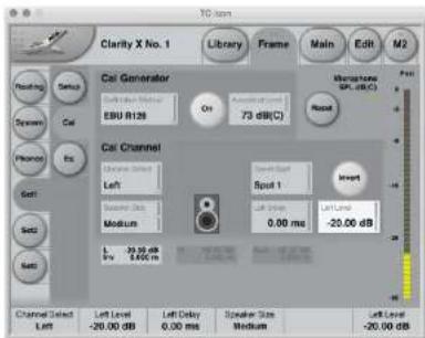
Fig. 48: Frame / Set 1 / Cal / Manual Calibration sub-page
! Editing the parameters on this page is not possible when the currently selected Speaker Set has been defined as "Ready" by pressing the Ready button on its Setup page. See "Speaker Set configuration" on page 66.
Manual Speaker Set Calibration – Step by Step
-
Choose a calibration standard (using the Calibration Method) parameter and the target level (using the Acoustical Level parameter) to aim for. This setting will depends on your application (TV, cinema etc.) and room size.
-
Select a Speaker using the Channel Select parameter.
-
Make sure that there are no obstacles between the speaker you are about to calibrate and the Reference Microphone.
-
Activate the Calibration Signal Generator by clicking the On button in the Cal Generator section.
-
Monitor the Microphone SPL level display on the right side of the page. For more information on reading this display and adjusting speaker levels correctly, see "Microphone SPL display and Reset button" on page 86.
-
Adjust the Level parameter for the speaker to match the value indicated by the Microphone SPL level display.
-
Select the next Speaker using the Channel Select parameter and repeat the procedure.
-
When all monitors have been calibrated, go to the Setup page for this Speaker Set and click the "Ready" button to indicate that this Speaker Set has been calibrated properly.
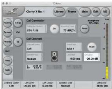
Fig. 49: Calibrating the left speaker in a 5.1 setup to EBU R128
Cal Generator section
Calibration Method parameter
Settings: EBU R128, SMPTE RP200, ATSC A85 Use the Calibration Method parameter to select the standard you want to follow when calibrating your Speaker Set(s). Changing this setting will adjust the Acoustical Level parameter and set the calibration signal and measures, accordingly.
Notes on EBU R128
EBU R128 (i.e. EBU Tech. Doc. 3343) has now superseded the older Tech. Doc. 3276. The calibration in R128 aligns the electrical signal to -23 LUFS, and recommends an acoustic reference level of 73 dB(C) SPL for broadcast. ATSC A/85 specifies an alignment level of -20 dBFS and reference levels between 76 and 85 dB(C), depending on room size. SMPTE RP200, which is relevant for cinema production, includes a 3 dB offset of the surrounds compared to the screen speakers, which are calibrated to 85 dB(C).
Clarity X contains studio presets for many applications, including music production, broadcast, cinema, or TV – with appropriate calibration and metering settings.
Calibration button
To activate the Calibration Tone Generator, click the On button in the Cal Generator section. The calibration tone will be played over the speaker selected in the Cal Channel section.
Acoustical Level parameter
Usually, you will select the calibration method/standard that you want to follow using the Calibration Method parameter in this section, and this will set the Acoustical Level parameter accordingly. However, you may also use the Acoustical Level parameter to manually select a level to calibrate against.
When setting this parameter, you should consider your application (e.g. cinema or TV) and the room size, and whether you mainly use far-field or near-field monitors.
Microphone SPL display and Reset button
When you have activated the signal generator using the On button in the Cal Generator section, the microphone reading will show Sound Pressure Level (SPL) measured with C-weighting and averaged with Leq.
Leq (equivalent continuous sound level) averages measurements over time in order to optimize the precision. This is especially important for subwoofer signals. Wait until the value displayed has settled to read the final level. This process may take approximately 10 seconds for a subwoofer signal.
When you change the speaker level, Leq is automatically reset.
You can also press the Reset button to the left of the Level indicator to reset measurements manually.
Cal Channel section
Channel Select parameter
Use the Channel Select parameter to select a Channel for calibration. The channels available for selection depend on the Speaker configuration as defined on the Configuration page for this Speaker Set. For more information, see "Configuration page" on page 66.
Speaker Size parameter
Settings: Small, Medium, Large
Use the Speaker Size parameter to define the physical size of the speaker that you have selected using the Channel Select parameter. This setting optimizes the precision of the Exposure and Dose estimates.
Please note that this parameter has no effect on the signal path.
Sweet Spot parameter
Settings: Spot 1 to Spot 4
Clarity X gives you the ability to calibrate all your speaker sets for up to four different optimized listening positions (“sweet spots”). Each sweet spot encompasses settings for every relevant parameter for every speaker in all three speaker sets.
Use the Sweet Spot parameter to select the sweet spot that you want to adjust.
For more information on sweet spots, see "Alternative sweet spots" on page 90.
Invert button
Use the Invert button to invert the phase of the audio signal going to the currently selected speaker.
When you have inverted the signal going to a speaker, "Inv" will be shown in the respective Speaker Level and Distance indicator.
! The Invert button state is part of the currently selected sweet spot, so switching to another sweet spot will change this parameter.
When you have selected a sub channel for editing, the Invert button will be replaced by the phase adjustment parameter.
Phase Adjustment parameter
Range: 0° to 360°
The phase adjustment parameter allows you to adjust the signal phase for sub channels. This allows you to move the overall phase of the subwoofer for the specific sweet spot.
Due to the subwoofer's crossover frequency, you may experience that the spectrum from the total speaker system is not optimal at the crossover frequency. Adjusting the phase parameter for the sub will give you the best possible spectrum from the total speaker system at the subwoofer crossover frequency. This parameter is stored as part of Clarity X Studio presets.
[Speaker] Delay parameter
Range: 0 to 100 ms
Use the Delay parameter to apply a delay to the selected speaker.
For more information, see "Speaker positions and Speaker Delay" on page 88.
! The Delay parameter setting is part of the currently selected sweet spot, so switching to another sweet spot will change this parameter.
For information regarding subwoofer delay settings, see "Compensation delay for subwoofers" on page 82.
[Speaker] Level parameter
Use the Level parameter to set the level for the selected speaker.
Adjust this parameter while the Calibration Tone Generator is active to match the value displayed by the Microphone SPL display on the right edge of the screen to the Acoustical Level parameter.
! The Level parameter setting is part of the currently selected sweet spot, so switching to another sweet spot will change this parameter.
Speaker Level and Delay
compensation indicators
The Speaker Level and Delay compensation indicators in the bottom half of the Cal Channel section will show you the levels and the applied delays for all speakers in the current Speaker Set.
Speaker positions and Speaker Delay
Why would you add delay to individual speakers in a surround setup?
When using a 5.x setup with monitors arranged in a circle (as with ITU 775), the distance from the listener to each main monitor is the same.
However, if space is limited, the three front monitors will often be arranged on a straight line instead of a circle. In this case, the center signal should be delayed to compensate for the center monitor being closer to the listener than the left and right monitor.
Your listening position might also be closer to the front speakers than to the back speakers. Again, you would delay the signal going to the front speakers to compensate for this fact.
Delaying signals properly is achieved by setting a speaker-specific delay (in milliseconds) to compensate for the delta between the ideal and the real speaker distance (measured in feet or meters depending on your Preferences settings). This way, the perceived distance from your listening position to each speaker will be identical, even though the actual distance varies.
For more information about speaker setup and signal delays, see "Delaying monitors" on page 190.
Measuring speaker distances and entering the required delay values
- Using a simple measuring band, measure the distance from you listening position to the speaker furthest from that position.
This is your reference value, and the signal going to this speaker will not have to be delayed.
- Write down this distance on a piece of paper – let's call it "A".
For the remaining speakers in your Speaker Setup, you will now use the Delay parameter for this speaker to add a "virtual" distance, so that the total distance to that speaker equals A.
-
Measure the distance to the next speaker and note it down – this is value "B".
-
Subtract B from A. Let's call the resulting delta value "C".
-
On the Cal page for this Speaker Setup (e.g. Frame / Set2 / Cal), select that speaker using the Channel Select parameter in the Cal Channel section.
-
Adjust the Delay parameter for this speaker until the distance shown by the Speaker Level and Distance indicator for that speaker equals "C".
-
Repeat this procedure for every speaker that is closer to your listening position than the speaker your measurements are based on.
Of course, you scan skip the procedure for all speakers that have the same distance to your listening position as the speaker your measurements are based on. So for a 5.1 setup where only the center speaker is closer to your listening position, you would only have to delay the signal going to the center speaker.
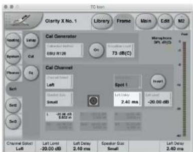
Fig. 50: Signals for the left and right speakers delayed by 2.4 ms to compensate for the center speaker being 80 cm closer to the listener
Speaker Delay Example
The distance between your listening position and the front left speaker is 1 meter.
The distance between your listening position and the back left speaker is 4 meters.
Accordingly, you'll want to add (4 minus 1 =) 3 meters to the signal going to the front left speaker, so that its perceived distance to you is the same as for the back left speaker.
- On the Cal page for this Speaker Setup, select the front left speaker using the Channel Select parameter in the Cal Channel section.
- Adjust the Delay parameter for the front left speaker until the distance shown by the "L" Speaker Level and Distance indicator is 3 meters.
Add a delay to the front left speaker until the distance shown is 3 meters. For fine-tuning the Delay parameter, see "Using Faders for fine adjustments" on page 48.
A shortcut to calculating and setting speaker distances
The speed of sound is approximately 340 m/s or 1130 ft./s. Accordingly, adding 1 millisecond of delay will be virtually move a speaker 30 centimeters/1 foot away from your listening position.
Alternative sweet spots
Engineers and audiophiles crave the sweet spot – the listening position where they are able to hear a mix the way it is intended to be heard. So what could be better than enjoying a calibrated monitor system with a well-defined sweet spot? Well, being able to define and recall multiple sweet spots.
If you are mixing a film score and the director stops by to listen, or if you are working in post production with the client sitting beside you, the last thing you want is to switch positions just to make sure that he get to hear how much effort you put into the mix. Being able to recall a previously defined sweet spot for the person sitting next to you is the most elegant and reliable approach. Think of it as making the sound as good as it can possibly be on the "producer couch" or in the director's chair – without having to move people, furniture or knobs.
Clarity X gives you the ability to calibrate all your speaker sets for up to four different listening positions. Comfortably select sweet spots from Icon or using your Remote control.
Clarity X sweet spots
Clarity X allows you to store and recall 4 separate calibrated sweet spots for each speaker set. These are four different groups of level settings for all speakers in a given set with fixed physical positions. Sweet spots can be defined and recalled for stereo and surround setups.
Sweet spots are extremely helpful when two or more people (e.g. mixing engineer and producer) are in the room, or if are working with a large mixing console that requires you to change your position depending on what part of the mix you are working on. You will find that it makes a rather big difference compared to having only one sweet spot.
Sweet spot parameters
Sweets spots include the Level, Delay and Phase Invert settings for each speaker. EQ settings are not part of the sweet spot.
Selecting sweet spots
You can select sweet spots as follows:
▶ with the Sweet Spot parameter on the Edit Main page
▶ with the Sweet Spot parameter on the Frame / Set / Calibration page as you calibrate speaker parameters
▶ with the Remote, where selection of sweet spot 2 and 3 can be assigned to the F-keys. For more information on setting up and using the Remote, see .
You can only select one sweet spot at a time. That sweet spot is common for all 3 speaker sets.
The Library: Recalling, storing and deleting settings
Clarity X software version 1.3.00 – Build 3275 – Reference manual (updated 2016-10-18)
Studio, Project, Routing, Engine and M2 presets
To use Clarity X effectively, you should make all required settings as described in this manual and then store them, so they can later be recalled. You may also want to name the settings you store and delete settings that are no longer required. All these features are described in this chapter.
You first need to understand the hierarchical structure of your Clarity X. This information is also available from the Library / Recall page by clicking on the Question Mark button.
Clarity X data structure overview
| Studio* | Project | Not in library | |||
| Routing | Engine | M2 | |||
| Frame / Speaker Sets 1, 2, 3 (Calibration, Bass Mngt, EQ) | √ | ||||
| Frame / Output Routing √ | |||||
| Frame / System / Master Clock | √ | ||||
| Frame / System / IO Settings √ | |||||
| Frame / Units √ | |||||
| Frame / System / Exposure Preferences | √ | ||||
| Frame / Input Routing √ | |||||
| Frame / System / Preselection of inputs (MADI) | √ | ||||
| Frame / Phones / Headphone Settings | √ | ||||
| Main / Edit √ | |||||
| Main / Meters √ | |||||
| M2 Settings √ | |||||
| Network, Lock, Mic Cal Level √ |
Fig. 51: Overview of the Clarity X data structure
* To store Studio Presets, Studio Setup has to be enabled.
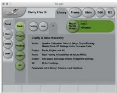
Fig. 52: Overview of the Clarity X data structure in TC Icon
Studio
A Studio Presets contains the following:
▶ Setup data for all three loudspeaker sets (Calibration, Speaker Size, Delay, Level Equalizer)
▶ Input Routing (as set on the Frame / Routing page)
▶ Master Clock Settings (as set on the Frame / System / Status page)
▶ I/O parameters (as set on the Frame / System / I/O page)
▶ Units and Exposure Preferences (as set on the Frame / System / Prefs page)
A Studio Preset is the highest hierarchical level in Clarity X. As the name implies, it should be used to store the physical configuration of your production environment and all relevant personal preferences.
Project
A Project Preset contains the following data:
▶ Input and Output Routing
▶ Engine settings. For more information, see "Engine" on page 94.
▶ M2: All settings for the LM8 meter as set under M2 and its subpages.
Route
A Route Preset contains the following data:
▶ Input Routings
▶ Pre-selection of Inputs (only applicable for MADI)
Engine
An Engine Preset contains the following data:
▶ All signal processing, mute and gain parameters as set on the Edit / Main and Edit / Format pages.
▶ M1 meter settings parameters as set on the Edit / Setup / M1 page.
▶ Measurement microphone and Signal Generator parameters as set on the Edit / Setup / Tone page.
- Clarity X Remote configuration as set on the Edit / Remote page.
▶ Headphone parameters as set on the Frame / Phones page.
The Library concept
The Library gives you access to all settings of all parameters of the currently selected Clarity X, organized as described under "Studio, Project, Routing, Engine and M2 presets" on page 92.
The Library as organized by function, then by Preset. That means that you would first decide what you want to do (e.g. recall previously stored data) and then select the hierarchy level/Preset type you want to recall.
Factory presets versus user presets
When recalling presets, you will see that there are two categories of presets: Factory presets and User presets.
▶ Factory presets can only be recalled, but not overwritten or deleted. If you change a Factory preset and you want to keep it, you have to store it as a User preset.
▶ User presets can be recalled, edited and stored, thereby overwriting the previous version.
Factory presets - 44.1-48 versus 44.1-96
Where possible, Factory presets are divided into 44.1-48 and 44.1-96 groups. Please note that there are some limitations to running 96 kHz, so if you never run 96 kHz or if you work with film 7.1, you can select the 44.1-48 range on the Frame / System / I/O / Clock page and thereby have the full feature set of Clarity X available at all times.
If you sometimes or primarily run 96 kHz, you may wish to have a constant feature set available for all sample rates. In this case you should select the 44.1-96 range.
For more information, see "Master Clock and AES Setup section" on page 62.
Factory presets and Fader assignment
In all Project and Engine factory presets, Fader 1 is assigned to Source select. Recalling a Factory preset is the only way to assign Source Select to a fader. Saving a Factory preset as a User preset will also save the Fader assignments, including Source Select.
For more information about Fader assignment, see "TC Icon faders" on page 48.
Recall page
Use the Library Recall page of the TC Icon software to recall (load) previously stored settings into the memory of the currently selected device.
All colored buttons and selected items on the Recall page are colored in green.
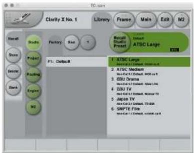
If it isn't already, select the device you want to control using the Select page – see "TC Icon modes: Base and Device operation" on page 47.
▶ Select the Library tab.
▶ Select the Recall page.
▶ Select the subpage for the Preset type you want to access: Studio, Project, Routing, Engine or M2.
For more information, see "Studio, Project, Routing, Engine and M2 presets" on page 92.
▶ Select between Factory and User preset groups by clicking the Factory or User button.
▶ Select a Preset you want to use.
▶ Click the large "Recall (Studio / Project / Routing / M2) Preset" button in the upper right corner to recall (activate) the selected preset.
The selected preset will be recalled.
Preset information
For many presets, additional information is stored as part of the preset. When you select such a preset, an inverted "Info" tag will appear at the bottom of the large Preset Recall button.
Fig. 54: M2 Preset Recall button with Info tag
Click the Info tag to display additional information about this preset in a modal dialog.
Click the OK button do close the dialog.
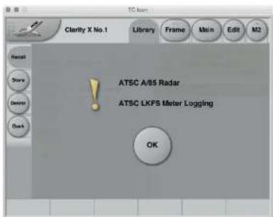
Fig. 55: Info display for M2 preset
Store page
Use the Library Store page of the TC Icon software to store (save) settings to a Memory Bank.
You can only store settings as User presets. Factory presets cannot be overwritten.
All colored buttons and selected items on the Store page are colored in red.
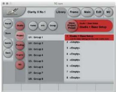
Fig. 56: Library Studio Store page
Storing Presets
If it isn't already, select the device you want to control using the Select page – see "TC Icon modes: Base and Device operation" on page 47.
▶ Select the Library tab.
▶ Select the Store page.
▶ Select the subpage for the Preset type you want to store: Studio, Project, Routing, Engine or M2.
! To store Studio presets, you need to enable Studio Setup on the Preferences page. For more information, see "Preferences" on page 152.
▶ Select a User Preset Group (U1 to U8).
There are 8 User Preset Groups, with each group holding up to 8 Presets.
▶ Select a Preset slot (1 to 8) in the currently selected group that you want to use.
- Click the large "Store (Scene / Route / Engine / Meter) Preset" button to store (save) your settings as a Preset.
The selected data type will be stored as a Preset. You can then recall this Preset – see "Recall page" on page 96.
Naming Presets
All user preset types can be (re)named.
To rename a preset:
On the Store page, select the preset that you want to rename.
Click the "Name" button.
▶ An on-screen keyboard will be shown.
▶ Use the on-screen keys or the physical keyboard of your computer to edit the name.
▶ Click the large Enter button to confirm the new name.
! Please note that the preset itself is not stored when you click the Enter button! To store the preset with its new name, click the large "Store (Scene / Route / Engine / Meter) Preset" button.
Adding Preset Information
You can add information to Presets you have created or modified. When recalling such a preset later, an inverted "Info" tag will appear at the bottom of the large Preset Recall button, allowing the user to access this additional information – see "Preset information" on page 96.
Operating the unit while renaming presets
Please note that even when renaming presets or adding information as described above, the faders for the previously accessed page are still available and operational. This means you can continue operating the faders even when the keyboard is shown on screen.
To add information to a preset:
▶ On the Store page, select the preset that you want to add information to.
▶ Click the "Info" button.
▶ An on-screen keyboard will be shown.
▶ Use the on-screen keys or the physical keyboard of your computer to edit the name.
▶ Click Enter to confirm.
! Please note that the Preset itself is not stored when you click the Enter button! To store the preset with the newly added information, click the large "Store (Studio | Project | Routing | Engine | M2) Preset" button.
Delete page
Use the Library Delete page of the TC Icon software to delete Presets from a Memory Bank.
You can only delete User presets. Factory presets cannot be deleted.
All colored buttons and selected items on the Delete page are colored in yellow.
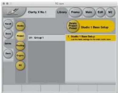
Fig. 57: Library Project Delete page
Storing Presets
If it isn't already, select the device you want to control using the Select page – see "TC Icon modes: Base and Device operation" on page 47.
▶ Select the Library tab.
▶ Select the Delete page.
▶ Select the subpage for the Preset type you want to delete: Studio, Project, Routing, Engine or M2.
! To delete Studio presets, you need to enable Studio Setup on the Preferences page. For more information, see "Preferences" on page 152.
▶ Select the User Preset Group (U1 to U8) containing the Preset you want to delete.
▶ Select the Preset slot (1 to 8) with the Preset you want to delete.
▶ Click the large "Delete (Studio | Project | Routing | Engine | M2)" button to delete (erase) the selected Preset.
You will be asked to confirm this operation before the Preset is actually deleted.
Operating the unit while deleting presets
Please note that even when deleting presets, the faders for the previously accessed page are still available and operational. This means you can continue operating the faders even when the keyboard is shown on screen.
Bank page
Use the Library Bank page of the TC Icon software to copy Scene / Routing / Engine / Meter Presets from one location to another.
You can copy Presets...
▶ from and to Memory Banks and
▶ from and to files.
Files can be transferred to other computers, allowing you to easily reuse your presets.
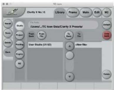
Fig. 58: Library Bank page
Copying Presets
If it isn't already selected, select the device you want to control using the Select page – see "TC Icon modes: Base and Device operation" on page 47.
▶ Select the Library tab.
▶ Select the Bank page.
▶ Select the subpage for the Preset type you want to copy to or from the device memory: Studio, Project, Routing, Engine or M2.
To copy from a Bank to a file on disk
▶ Select the "From Bank" button above the first column. The second column will switch to "To File" accordingly.
▶ Specify the folder where the file should be written in the "File Folder" field.
▶ If you want to overwrite an existing file, select it in the right column.
If you select "New file" instead, you will be prompted to specify the file name.
▶ Click the "Copy Bank" button.
To copy from a file on disk to a Bank
▶ Select "From File" in the first column. The second column will switch to "To Bank" accordingly.
▶ Specify the folder from where the file should be read in the "File Folder" field.
▶ Click the "Copy Bank" button.
Signal Source and Speaker Set configuration
Clarity X software version 1.3.00 – Build 3275 – Reference manual (updated 2016-10-18)
Main Edit page
Use the Main Edit page to specify basic input and output parameters.
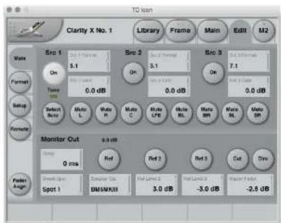
Fig. 59: Main Edit page
Source (1 to 3) section
Src 1 to Src 3 selection buttons
Click on a button to select the respective signal source module. The button of the currently selected Source module is highlighted.
For information on assigning the physical inputs of Clarity X to the three Source modules, see "Setting up audio and syncing" on page 57.
Src 1 to Src 3 Format parameters
Use the Src 1 to Src 3 Format parameters to specify the format of the audio signal fed into the respective Source Module.
Click on a button to select the respective Signal Source Module. The button of the currently selected Source module is highlighted.
Setting the Source Format correctly is required to ensure that features such as Downmix work as expected. E.g., if you set it to Stereo, you will not be able to use the Multi-channel Downmix feature.
To specify the Speaker Set, use the Speaker Set pages. For more information, see "Speaker Set configuration" on page 66.
Available settings are Stereo, 5.1 and 7.1.
Src 1 to Src 3 Gain parameters
Use the Src 1 to Src 3 Gain parameters to adjust the gain of the respective Source Module.
Tip: Use your input meter to gain-align signal sources that you want to A/B compare. Assign Source selection to a key on your Remote Control and check the Main display as you switch between them.
Tone „LED“
When the Signal generator on the Edit / Setup Tone page has been activated, the Tone "LED" will be lit.
When the Signal Generator is enabled (running), you only need to push one of the Src buttons on the Main edit page to stop the Signal Generator and switch to that Source. You can also stop the Signal Generator by clicking in a Source Module on the Routing page.
Select Solo button
Click this button to switch the adjacent set of buttons from Mute to Solo.
When the Select Solo button is disabled, the adjacent button set allows you to mute channels.
When the button is enabled (highlighted), the labels of the adjacent buttons change from "Mute [Channel Identifier]" to "Solo [Channel Identifier]", and you can use them to solo channels.
Using Mute and Select Solo effectively
Let's assume that you are working on the center speaker signal in your mix. First, you would mute the center speaker with the Mute button. If you then click the Select Solo button, all speakers except for the center speakers will be muted. This allows you to easily get an overview of the center speaker signal's effect on the total mix.
Mute buttons
Click a button to mute the respective channel in the selected Signal Source Module. There is one button for each channel of a 7.1 signal. Muted channels are highlighted. To unmute, click the respective button again.
Solo buttons
When you have enabled the Select Solo button, the Mute buttons are replaced by Solo buttons, allowing you to solo channels. You can solo multiple channels.
Monitor Out section
Delay parameter
Use the Delay parameter to apply an AV delay to the signal sent to currently active speaker set. This delay is added to the speaker-specific delay set for the Speaker Set.
Ref / Ref 2 / Ref 3 Select buttons
Use the buttons to select a Reference Level.
Cut button
To cut the signal to the speakers altogether, click the Cut button.
This function is also available from the Remote Control. For more information, see "Clarity X Remote Control" on page 124.
Dim button
To bring the volume down by 18 dB, click the Dim button. This is done digitally for the AES outputs. For the analog outputs, the 18 dB attenuation is performed in the analog domain, expanding the dynamic range instead of reducing it.
This function is also available from the Remote Control. For more information, see "Clarity X Remote Control" on page 124.
Sweet Spot parameter
Settings: Spot 1 to Spot 4
Clarity X gives you the ability to calibrate all your speaker sets for up to four different listening positions. Each Sweet Spot encompasses settings for every relevant parameter for every speaker in all three speaker sets.
Use the Sweet Spot parameter to select the Sweet Spot that you want to adjust.
For more information on sweet spots, see "Alternative sweet spots" on page 90.
Speaker Set parameter
Use the Speaker Set parameter to select the Speaker Set.
! In a normal usage scenario, you would control both Reference Levels and Speaker Set selection using the Remote control. For more information, see "Clarity X Remote Control" on page 124.
Ref Level 2 and Ref Level 3 parameter
Use the Ref Level 2 and Ref Level 3 parameters to define secondary and tertiary reference levels.
Ref 2 and Ref 3 Level parameters are relative to the (Main) Ref Level, i.e., you specify the offset.
Master Fader parameter
Use Master Fader parameter to set the Master Output level.

tc electronic
Signal Source and Speaker Set configuration
If the Remote Control is connected to your Clarity X, this parameter will be disabled.
Tone page
Use the parameters on the Tone page to create and measure test signals.
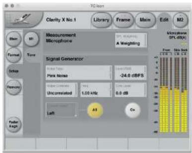
Fig. 60: Tone page
Measurement Microphone section
SPL Weighting parameter
Settings: A Weighting, C Weighting Use the SPL Weighting parameter to specify the sound pressure level measurement filter that should be used for the measurement.
The measurement will reflect what the Reference Microphone „sees“ – typically, the test signal created with the Signal Generator or your actual sound mix.
The Microphone SPL display in the upper right corner will reflect the selected curve, with the label reading either "dB(A)" or "dB(C)".
Signal Generator section
Noise Type parameter
Settings: Sine, White Noise, Pink Noise, Two Octave 1 kHz, Two Octave 50 Hz Use the Noise Type parameter to select the signal type that the Signal Generator should generate when activated.
Two Octave 1 kHz setting This is a pink noise signal bandwidth-limited to 2 octaves from 500 Hz to 2 kHz.
Two Octave 50 Hz setting This is a pink noise signal bandwidth-limited to 2 octaves from 25 Hz to 100 Hz.
Level RMS parameter
Range: -40 to 12 dBFS Use the Level RMS parameter to set the level of the test signal.
Noise Correlate parameter
Settings: Correlated, Uncorrelated If you have enabled the All button to send the test signal to all channels, and if you have set the Noise Type parameter to White Noise, Pink Noise, Two Octave 1 kHz or Two Octave 50 Hz, you can use the Noise Correlate parameter to specify if the signals should be correlated or uncorrelated between channels.
Freq parameter
Range: 20 Hz to 20 kHz
If you have set the Noise Type parameter to Sine, you can use the Freq parameter to set the frequency for the sine wave. For fine-tuning the frequency, see "Using Faders for fine adjustments" on page 48.
Going through the frequency list, you will find 440 Hz (standard pitch) and 997 Hz settings. 997 Hz is often used instead of 1 kHz due to its robustness towards resampling in peak meters etc.
Sine Level parameter
Setting: 0 to 12 dB
If you have set the Noise Type parameter to Sine, you can use the Sine Level parameter to set an offset level for the sine wave relative to the noise types.
Channel Select parameter
Settings: Left, Right, Center, LFE, Back
Left, Back Right, Side Left, Side Right
Use the Channel Select parameter to select the
Channel the test signal should be sent to.
This parameter is not editable if you have enabled the All button.
All button
To send the signal from the Signal Generator not only to the selected channel, but to all channels, click the All button.
On button
To activate the Signal Generator, click the On button.
Microphone SPL and Signal Meter section
When the Signal Generator is active,
▶ the Peak Meters on the left edge of the Tone page will show the levels of the test signals as they are sent out to the currently selected Speaker Setup
▶ the Microphone SPL display in the upper right corner will display the signal level measured with the microphone connected to the MIC IN jack.
Clarity X Main view – Meters and Operation
Clarity X software version 1.3.00 – Build 3275 – Reference manual (updated 2016-10-18)
Clarity X main view - introduction
The Main view is the "dashboard" that you use to monitor and control your studio setup after you have connected and configured your studio setup as described in the previous sections of this manual. It provides a wealth of information, allowing you to see what is going on.
The left pane shows information about the input, while the right pane displays output-related information.
The two-panes/two pages approach also allows you to access even more relevant functions and statistics with the click of a button.
▶ Click the Page 1/Page 2 button in each pane to switch this pane to the other page.
For more information, see:
▶ "Main view – left pane – page 1" on page 109
▶ "Main view – left pane – page 2" on page 111
▶ "Main view – right pane – page 1" on page 112
▶ "Main view – right pane – page 2" on page 114
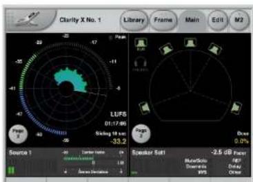
Fig. 61: Clarity X Main View – input and output panes showing Page 1
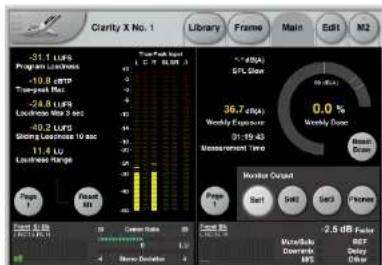
Fig. 62: Clarity X Main View – input and output panes showing Page 2
Main view – left pane – page 1
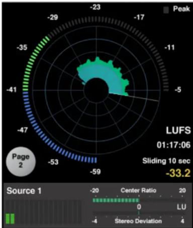
radar
| Parameter | Value | | --------------- | ------ | | Peak | -23 | | Center Ratio | -59 | | Center Ratio | -53 | | Center Ratio | -47 | | Center Ratio | -41 | | Center Ratio | -35 | | Center Ratio | -29 | | Center Ratio | -17 | | Center Ratio | -11 | | Center Ratio | -5 | | Center Ratio | -4 | | Center Ratio | -2 | | Center Ratio | -1 | | Center Ratio | 0 | | Center Ratio | 20 | | LU | 0 | | Stereo Deviation | 4 | | Sliding 10 sec | -33.2 |Fig. 63: Clarity X Main View, left pane, page 1 showing the Radar Meter and Source overview, Stereo Deviation Meter and Center Ratio Meter
Page 1 of the Main view's left pane shows... ▶ the LM8 Radar meter (M1)
▶ the channel overview for the currently selected Source
- the Stereo Deviation Meter (if it has been selected on the Edit / Setup / M1 page)
- the Center Ratio Meter (if it has been selected on the Edit / Setup / M1 page)
Radar Meter
The radar display shows your short-term (S) loudness history over time. The outer ring shows the Momentary Loudness (M), while a descriptors can be assigned to display a parameter you choose – for instance Program Loudness (I) and Loudness Range (LRA).
To configure the meter, use the Edit / Setup / M1 page.
For more information about M1 configuration, see "M1 Meter configuration" on page 149.
For general information about the Loudness Radar Meter, see "M2 – The LM8 Meter" on page 128.
Source Overview
The Source Overview gives you a complete overview of the channels in the currently selected Source Module.
The meters are quite small and not meant for "reading" the dB values of each channel, but to quickly spot if one or more channels suddenly drops out. In a stereo setup, this would immediately be audible, but for instance in a 7.1 surround environment, one of the rear or side speakers may go silent for a while before you notice it.
On page 1, the name of the currently selected source module is shown above the channel display, e.g. "Source 2".
Fore more information on assigning the physical inputs of Clarity X to the Source Modules, see "Signal routing" on page 59.
Even though you probably put most of your efforts into your surround mix, it is important to remember that stereo is still the format that actual viewers are most likely to be listening to, as most films and TV shows are watched from a living room with stereo speakers.
The Stereo Deviation Meter shows you how well your surround mix will translate into stereo.
Based on state-of-the-art loudness measurement algorithms, the Stereo Deviation Meter compares the loudness of your surround mix to the loudness of an emulated downmix version of that mix. This shows if your mix will be too loud or too soft once it has been downmixed to stereo. In addition, any difference between the two could mean that there might be a problem with your surround mix.
Center Ratio Meter
The Center Ratio Meter displays the balance between the center channel and the rest of the channels in your surround mix. It is basically a loudness measure of the center channel versus the rest, and the way the meter reflects this balance is based on analysis of a number of film and TV productions.
We worked from content examples with high speech intelligibility and measured the balance of the center channel versus the rest. We then did exactly the same using some sources with poor speech intelligibility. This way we have been able to set a target that correlates with high intelligibility.
If the Center Ratio Meter goes to the left, the center channel is too soft compared to the rest of the channels in order to maintain good intelligibility.
If the Center Ratio Meter goes to the left, the center channel is probably too loud.
It is important to stress that the center channel also carries other sound sources than speech and that the meter is a visual guideline rather than a fail-safe, fixed solution, so be sure to always trust your ears while using this meter as a guideline.
Main view – left pane – page 2
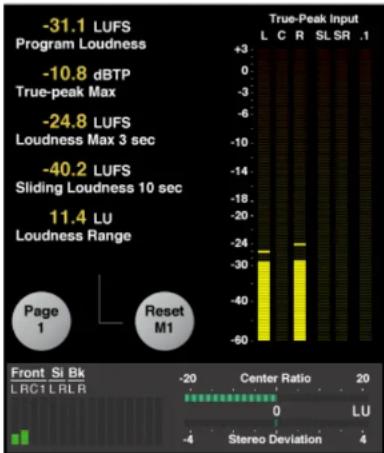
bar
| Category | Value | |---|---| | True-Peak Input | -31.1 LUFS Program Loudness | | True-Peak Input | -10.8 dBTP True-peak Max | | True-Peak Input | -24.8 LUFS Loudness Max 3 sec | | True-Peak Input | -40.2 LUFS Sliding Loudness 10 sec | | True-Peak Input | 11.4 LU Loudness Range | | Center Ratio | -20 | | Center Ratio | 20 | | Stereo Deviation | -4 | Front Si Bk LRC1 LRLR 0 LU Stereo Deviation 4Fig. 64: Clarity X Main View, left pane, page 2 showing Radar statistics, True Peak Meter and Source overview, Stereo Deviation Meter and Center Ratio Meter
Page 2 of the Main view's left pane shows...
▶ the LM8 Radar Statistics page,
▶ the M1 Reset button,
▶ the channel overview for the currently selected Source
▶ the Stereo Deviation Meter (if it has been selected on the Edit / Setup / M1 page)
▶ the Center Ratio Meter (if it has been selected on the Edit / Setup / M1 page).
For more information about the Statistics Page, see "LM8 Statistics page" on page 143.
For more information about the True Peak Meter, see "True-peak meters" on page 136.
For more information about the channel overview, the Stereo Deviation Meter and the Center Ratio Meter, see the parameter descriptions in "Main view – left pane – page 1" on page 109.
On page 2, the channel are shown above the channel display as follows:
Front L Front Left
Front R Front Right
Front C Front Center
Si L Side Left (for 7.1 setups)
Si R Side Right (for 7.1 setups)
Bk L Back Left
Bk R Back Right
Reset M1 button
Click the Reset M1 button to reset the M1 Radar Meter. The Meter can also be reset from the Remote Control.
Main view – right pane – page 1
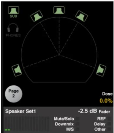
radar
| Speaker Set1 | Mute/Solo | Downmix | M/S | REF | Delay | Other | | ------------ | --------- | ------- | --- | --- | ----- | ----- | | Speaker Set1 | -2.5 dB | -2.5 dB | -2.5 dB | -2.5 dB | -2.5 dB | -2.5 dB |Fig. 65: Clarity X Main View, right pane, page 1 showing the current speaker set, the Dose Meter, the Speaker Set overview, and various status indicators
Page 1 of the Main view's right pane shows...
▶ a visual representation of the currently select-
ed Speaker Set,
▶ the Dose Meter
▶ the channel overview for the Speaker Set,
▶ Mute/Solo status indicator
Downmix status indicator
▶ M/S status indicator
▶ REF level status indicator
▶ Delay status indicator
▶ "Other" status indicator.
Speaker Set display
▶ To mute or unmute a speaker, click its icon.
! Headphones can be selected and muted as well, even separately for the left and right side.
Usually, you would mute, unmute and solo speakers using the Remote Control. for more information, see "Clarity X Remote Control" on page 124.
Dose Meter
For more information about Dose Metering, see "Dose Metering" on page 119.
Speaker Set Overview
The Speaker Set Overview gives you an overview of the channels in the currently selected Speaker Set. Just like the Source Overview in the left pane, these small meters are not meant for “reading” absolute values, but to quickly spot when channels suddenly drop out.
On page 1, the name of the currently selected Speaker Set is shown above the channel display, e.g. "Speaker Set 1".
Status indicators
Mute/Solo status indicator
This indicator will light up if one or multiple speakers in the currently selected Speaker Set have been muted or soloed.
Downmix status indicator
This indicator will light up if the Downmix function on the Format page has been engaged. For more information, see "Multi-channel downmix section" on page 116.
M/S status indicator
This indicator will light up if the Mono or side functions on the Format page have been engaged. For more information, see "Mono/Side section" on page 117.
REF level status indicator
This indicator will light up green when the current Speaker Setup is operated at reference level.
It will light up yellow if there is a problem with the reference level, e.g. when the Speaker Set has not been calibrated.
Delay status indicator
This indicator will light up if a delay has been applied to the monitor signal on the Main Edit page. For more information, see "Monitor Out section" on page 103.
"Other" status indicator
This indicator will light up if one of the following signal processing functions has been activated:
▶ Noise Floor Zoom. For more information, see "Noise Floor section" on page 118.
▶ Phase Inversion. For more information, see "Invert Phase section" on page 116.
▶ Signal Generator (Tone). For more information, see "Speaker Set calibration" on page 78.
Main view – right pane – page 2
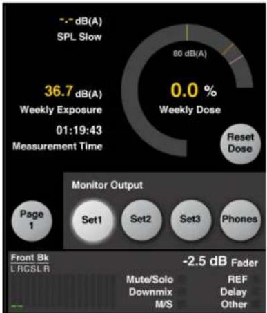
pie
SPL Slow 36.7 dB(A) Weekly Exposure 01:19:43 Measurement Time 80 dB(A) 0.0 % Weekly Dose Reset Dose Monitor Output Page 1 Set1 Set2 Set3 Phones Front Bk LRCSLR -2.5 dB Fader Mute/Solo Downmix M/S REF Delay OtherFig. 66: Clarity X Main View, right pane, page 2 showing the Dose Meter, the Reset Dose button, the Speaker Set selection buttons and various status indicators
Page 2 of the Main view' right pane shows...
▶ the Dose Meter and the Reset Dose button
▶ the Speaker Set selection buttons
▶ the channel overview for the Speaker Set,
▶ Mute/Solo status indicator
Downmix status indicator
▶ M/S status indicator
▶ REF level status indicator
▶ Delay status indicator
▶ "Other" status indicator.
Dose Meter
The Dose Meter shows the following information:
▶ Exposure Level ( L_EX ) per day or week (depending on the Time Period parameter setting on the Preferences page)
▶ Dose Percentage per day or week (depending on the Time Period parameter setting on the Preferences page). Values below 10 % are shown with decimals.
Use the Reset Dose button to reset the Dose Meter.
For basic information about Dose Metering, see "Hearing loss protection" on page 24 and "Dose Metering" on page 119.
For configuring the Dose Meter, see "Exposure & dose estimation section" on page 154.
For information about configuring Speaker Sets, see "Speaker Set configuration" on page 66.
For information about the channel overview for the Speaker Set and the various state indicators, see the parameter descriptions in "Main view - right pane - page 1" on page 112.
On page 2, the channel are shown above the channel display as follows:
Front L Front Left (for all setups)
Front R Front Right (for all setups)
Front C Front Center (for 5.1 & 7.1 setups)
Si L Side Left (for 7.1 setups)
Si R Side Right (for 7.1 setups)
Bk L Back Left (for 5.1 & 7.1 setups)
Bk R Back Right (for 5.1 & 7.1 setups)
Downmix and other processing functions
Clarity X software version 1.3.00 – Build 3275 – Reference manual (updated 2016-10-18)
Edit Format Page
Use the Edit / Format page to access and configure signal processing functions.
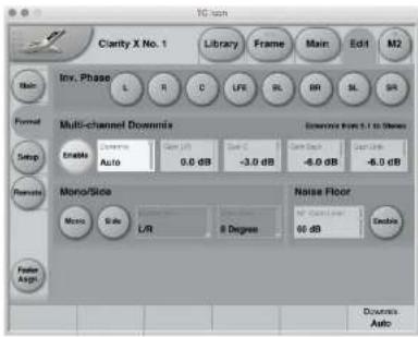
Fig. 67: Edit / Format page
Invert Phase section
Use the buttons in the Invert Phase section to selectively invert the phase of one or multiple input channels.
There is one button for each channel of a 7.1 signal. You can invert multiple channels. Inverted channels are highlighted.
Multi-channel downmix section
! To use the Multi-channel downmix functions described in this section, you need to specify the selected Source Module's format on the Main Edit page. The audio signal's format will not be detected automatically. For more information, see "Main Edit page" on page 102.
Downmix Enable button
To convert...
▶ a 7.1 signal from the currently selected Source Module to Stereo or 5.1,
▶ a 5.1 signal from the currently selected Source Module to Stereo or
...click the Enable button in the Multi-channel downmix section.
! The Downmix section cannot be enabled when the Source Format of the currently selected Source Module has been set to Stereo, as a "Stereo to Stereo" downmix does not make sense.
If you want to downconvert a Stereo (or a 5.1/7.1 surround) signal to Mono, use the Mono button in the Mono/Side section instead. For more information, see "Mono/Side section" on page 117.
Downmix parameter
Settings: Stereo, 5.1, Auto Use the Downmix to select the format that the signal should be downmixed to.
Stereo setting When Multi-channel downmix is enabled and Downmix is set to Stereo, a 5.1 or 7.1 source signal will be converted to Stereo.
5.1 setting When Multi-channel downmix is enabled and Downmix is set to 5.1, a 7.1 source signal will be converted to 5.1.
Auto setting
When Multi-channel downmix is enabled and Downmix is set to Auto,
▶ a 5.1 source signal will be converted to Stereo,
▶ a 7.1 source signal will be converted to Stereo when using a Stereo Speaker Setup,
▶ a 7.1 source signal will be converted to 5.1 when using a 5.1 Speaker Setup,
▶ a 5.1 source signal will not be affected when using a 5.1 Speaker Setup,
▶ a Stereo signal will not be affected.
Gain parameters (L/R, C, Back, Side)
Use the Gain parameters to attenuate signal components in the downmixed Stereo signal.
You can attenuate each signal or signal pair by up to 12 dB or remove it from the downmixed signal completely (Off setting).
When downmixing from 7.1 to 5.1, only the back and side channel parameters are editable. The L/R and C parameters are grayed out and have no effect on the downmix.
For an overview of downmix options and the resulting signal processing, see "Audio formats and bass management modes – overview" on page 69.
Mono/Side section
Mono button
To convert the Source Signal to Mono, press the Mono button.
Conversion to Mono occurs after the Multi-channel downmix, if this function has been engaged.
Side button
To only listen to the Side signal components, press the Side button.
The Side signal component contains only the information that differs between the left and right channels of a stereo signal.
Monitoring the Side signal component only is especially interesting when comparing a data-reduced format – such as MP3 or AAC – to a linear signal, or to a data-reduced signal at a different bit rate.
Conversion to Mono occurs after the Multi-channel downmix, if this function has been engaged.
Settings: L/R, Center
If you have applied Mono or Side Channel processing using the Mono or Side button, you can use the Monitor M/S parameter to define over which speaker(s) the Mono or Side signal should be played back.
Noise Floor section
Use the parameters in the Noise Floor section to configure and activate the Noise Floor Zoom feature.
About Noise Floor Zoom
Noise is a potential source of annoyance that may clutter up the clarity of your mix. There may be one or more noise sources in your system that are almost inaudible.
With the Noise Floor Zoom feature, you get a virtual „noise floor magnifying glass“ that zooms in on your noise floor before the signal reaches Clarity X by adding up to 70 dB of gain to your output.
tally activated during playback, Clarity X provides a hard clip protection at -20 dBFS, ensuring that nothing and no-one gets hurt.
Noise Floor Zoom Enable button
To enable Noise Floor zoom, click the Enable button.
NF Zoom Level parameter
Use the NF Zoom Level parameter to define by how many dBs the signal level present at the currently selected Source Module should be raised when Noise Floor Zoom is active.
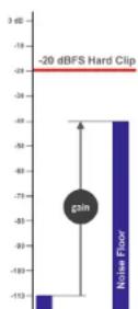
Fig. 68: Noise Floor Zoom
Obviously, such a feature calls for protection as it could damage your speakers, or even worse: your eardrums. To ensure that this doesn't happen if the Noise Floor Zoom feature is acciden-
Dose Metering
Clarity X software version 1.3.00 – Build 3275 – Reference manual (updated 2016-10-18)
Hearing Loss
For anyone working professionally with audio, the sense of hearing is essential. Unfortunately, sound that damages our hearing is not necessarily painful or even annoying – see Fig. 66. Note how audio professionals fall in a dangerous category with a high risk of being sometimes under unsafe or even traumatic listening conditions.
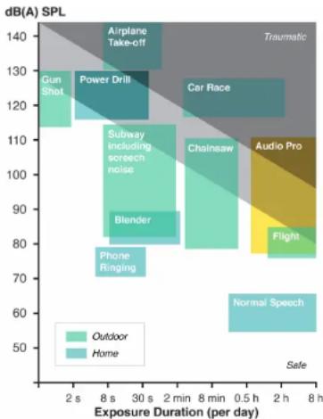
heatmap
dB(A) SPL | Exposure Duration (per day) | Outdoor (dB(A) SPL) | Home (dB(A) SPL) | | :--- | :--- | :--- | | 2 s | 115 | 140 | | 8 s | 110 | 130 | | 30 s | 105 | 120 | | 2 min | 100 | 110 | | 8 min | 95 | 100 | | 0.5 h | 90 | 90 | | 2 h | 85 | 80 | | 8 h | 80 | 70 | Airplane Take-off Power Drill Gun Shot Car Race Subway including screech noise Blender Phone Ringing Audio Pro Normal Speech Airplane Take-off Car Race Audio Pro Normal Speech Gun Shot Power Drill Blender Phone Ringing Normal Speech Normal Speech TraumaticFig. 69: Noise-induced hearing loss risks
Furthermore, recent clinical trials suggest that noise-induced damage to hearing has progressive consequences that are considerably more widespread than are revealed by conventional testing. If medical trends continue, the light gray zone of Fig. 66 will be no-go for professionals before long.
Thanks to new techniques to estimate actual sound exposure, Clarity X can help you become aware of potentially damaging work-practice before it's too late. Clarity X can also help you perform better mixes by keeping an ear on when it's time for a break.
Sound Exposure
Most audio professionals are familiar with sound pressure level (SPL) and anchor points such as threshold of hearing (0 dB SPL), normal speech (60 dB SPL) and one or two high SPL references.
However, the relevant metric to consider for projecting hearing loss typically isn't SPL but sound exposure – i.e. the A-weighted sound pressure squared and integrated over a period of time covering the exposure.
For any calibrated Speaker Setup or headphones, Clarity X continuously estimates the resulting sound exposure, even when switching between sources and formats.
! If the currently selected Speaker Setup has not been calibrated and declared as Ready, the Dose Meter will show "Not Cal". For more information, see "Speaker Set configuration" on page 66.
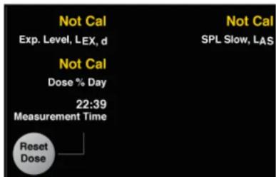
Fig. 70: Clarity X Dose Meter showing "Not Cal" for a Speaker Setup not declared as Ready
For more information about Speaker Setup calibration, see "Speaker Set calibration" on page 78.
Sound Exposure Level
Instead of displaying the raw sound exposure with its unpractical unit, Clarity X shows sound exposure level (SEL), which – like SPL – is logarithmic and relative to the threshold of hearing in humans at 1 kHz.
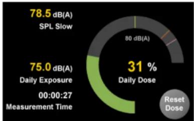
pie
| Metric | Value (dB(A)) | |---|---| | SPL Slow | 78.5 | | Daily Exposure | 75.0 | | Measurement Time | 00:00:27 | | Daily Dose (%) | 31 | Reset DoseFig. 71: Clarity X Dose Meter and Dose Reset button as seen in the right pane of the TC Icon Main View
Sound Exposure Level versus Sound Pressure Level
Despite both measurements having the unit [dB(A)], Sound Exposure Level (SEL) should not be confused with Sound Pressure Level (SPL).
SEL is a measure of total sound energy within a certain time frame, while SPL typically is used as a momentary measure.
Time period for Dose Metering (Day / Week) The normal time intervals to consider for SEL is day or week, such that the SEL and Dose% are normalized to an 8 hour day or to a 40 hour week, respectively.
Clarity X allows either interval to be used for the estimation of exposure. Set the preferred time period on the Frame / System / Preferences page. For more information, see “Exposure & dose estimation section” on page 154.
Dose Percentage (Dose %) indicator
Dose % relative to maximum safe exposure is a way of showing cumulative dose of variant sound sources, and generally the easiest metric to consider for using Clarity X safely.
With the exposure interval set to Day, your dose should stay below 100 % each day, and with a safety margin if other significant exposure is expected later in the day (e.g., going to the movies, a concert, or a club).
If you are working in one studio in the morning and in another one in the afternoon, reset the Dose measurement before starting each session and use simple addition to estimate your daily total - e.g. 35% + 50% = 85% .
Listening fatigue
As listening fatigue is individual, also use Dose % to notice which milestones you need to observe to keep sharp – e.g. for each 10 % or 15 % increase.
Customizing Dose Metering with the Criterion parameter
Dose % is a further interpretation of sound exposure, and it requires a 100 % criterion to be specified.
Based on medical recommendations, the default 100 % criterion in Clarity X is a SEL of 80 dB(A) – i.e., the light gray border of Fig. 66.
This criterion, however, can be adjusted, e.g. to a less conservative setting such as 85 dB(A).
Set the Criterion parameter on the Frame / System / Preferences page. For more information, see "Exposure & dose estimation section" on page 154.
Dose Percentage display
The Dose Meter shows the Sound Exposure as a "donut"-style gauge.
Read the colors and patterns shown by the Dose Meter as follows:
Dose Reset
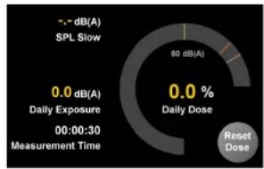
pie
| Category | Value | |---|---| | - - dB(A) SPL Slow | 80 dB(A) | | 0.0 dB(A) Daily Exposure | 0.0 % | | 00:00:30 Measurement Time | 0.0 % | Reset Dose0% Dose is what you will see right after resetting the Dose Meter.
Green: You're good!
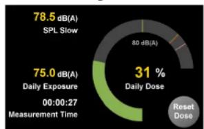
pie
| Metric | Value | |---|---| | SPL Slow | 78.5 dB(A) | | Daily Exposure | 75.0 dB(A) | | Measurement Time | 00:00:27 | | Daily Dose (%) | 31 | Reset Dose (implied by context)Fig. 73: Dose Meter in the green
From 0 to 99% , you are in the green area, and there would be no reason to worry about your hearing.

tc electronic
Dose Metering
Yellow: Now you should worry
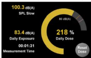
pie
| Category | Value | |---|---| | SPL Slow | 100.3 dB(A) | | Daily Exposure | 83.4 dB(A) | | Measurement Time | 00:01:31 | | Daily Dose | 218 % | | Reset Dose | (unlabeled segment) | 80 dB(A) (gray segment) |Fig. 74: Dose Meter over 99%
If the Dose Meter turns yellow, you should start putting attention to your mix levels.
You might consider taking a break or lowering the level for some time.
Red/white stripes: Don't get here
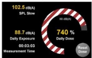
pie
| Category | Value | |---|---| | SPL Slow | 102.5 dB(A) | | Daily Exposure | 88.7 dB(A) | | Measurement Time | 00:03:03 | | Daily Dose | 740 % | Reset Dose | (implied by context). The chart is labeled '740 % Daily Dose'.Fig. 76: Dose Meter – critical dose
At this point you have overly exceeded the limits of what's good for you and your ears in the long run. It's definitely time to stop.
Red: It's serious
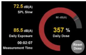
pie
| Category | Value (dB(A)) | |---|---| | SPL Slow | 72.5 | | Daily Exposure | 85.5 | | Measurement Time | 00:02:07 | | Daily Dose | 357 | Reset Dose (implied by context) | 80 dB(A) (unknown label) |Fig. 75: Dose Meter in the red
If you find the Dose Meter turning red, you should definitely take action:
Take a longer break, turn down your speaker system for a good while.
Clarity X Remote Control
Clarity X software version 1.3.00 – Build 3275 – Reference manual (updated 2016-10-18)
Using the Remote Control
Once you have configured Clarity X and the attached Speaker Sets properly, use the included Clarity X Remote Control for daily operation. This remote control is a natural extension of Clarity X, putting all relevant functions at your fingertips.
Remote Control Features
▶ Instant access to three different user-defined Reference Level settings.
▶ 3 programmable switches F1-F3
▶ Direct selection of Speaker Sets and Sources
▶ Mute/unmute and solo function for each monitor in the setup.
▶ Easy Master Level adjustment via large dial.
Clarity X Remote Control reference
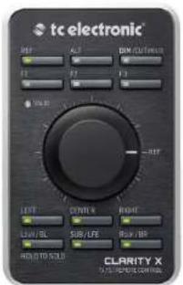
Fig. 77: Clarity X Remote Control
1. REF - Reference Level key
Press the Reference Level key to recall your reference listening level, which was determined during your initial speaker and room calibration. When it is lit, the volume knob is disabled. If you press the Reference Level key again, the level jumps to the position of the volume knob.
2. ALT Key
Use the ALT key to select your alternative Speaker set – or any output for that matter.
Available settings are Set 2, Set 3 and Phones.
The alternative Speaker Set is defined in the TC Icon software on the Edit / Remote page. See "Remote Function Keys section" on page 127.
3. DIM/CUT key
To bring the volume down by 18 dB, press the DIM key. This is done digitally for the AES outputs. For the analog outputs, the 18 dB attenuation is performed in the analog domain, expanding the dynamic range instead of reducing it.
To un-DIM, press the DIM/CUT key once.
To cut the signal to the speakers altogether, press and hold the DIM key.
If you have applied CUT and press the DIM/KEY once, you will switch to DIM level. To un-DIM, press the DIM/KEY again. This setup allows you to go from DIM to CUT and back to DIM instead of full level.
Clarity X Remote Control reference ctd.
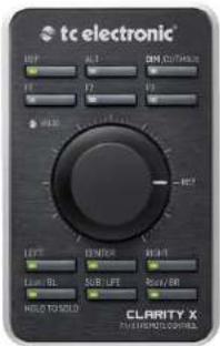
4. F1 to F3 - Function keys
The Function keys can be configured by the user using the Edit / Remote page of the TC Icon software. See "Remote Function Keys section" on page 127.
5. Master Volume Dial and VALID LED
Use the Master Volume Dial to set the volume for the currently selected Speaker Set.
When operating the Master Volume Dial, the Valid LED will blink shortly for every 6 dB gain change. This allows you to perform precise 6 dB gain changes.
The "REF" marker on the volume knob defines your reference listening level, which you specify
during the initial speaker and room calibration. Placing the Master Volume dial at the Ref marker is equivalent to pressing the REF button (1).
The volume dial is disabled when the Reference Level key (REF) is enabled.
When the current position of the volume dial knob corresponds to the actual level, the VALID LED will be lit.
6. Mute/Unmute/Solo buttons for each channel
Use these keys to mute or solo individual speakers in your surround mix:
L: Left
C: Center
R: Right
▶ Lsur: Left surround
SUB: Subwoofer
▶ Rsur: Right surround
The LEDs of these keys indicate the current state for a channel as follows:
▶ LED on: Speaker on
▶ LED off: Speaker muted
▶ LED flashing: Speaker solo
Muting and unmuting a speaker
▶ To mute a speaker/channel, press the respective key.
▶ To unmute a speaker/channel, press the respective key again.
Solo Function
To activate the Solo function for a speaker/channel, press and hold the respective key.
To deactivate the Solo function, press (but do not hold) the respective key again. This will return the speaker to the previous state (active or muted).
Working with 7.1 setups
If you are working with a 7.1 setup, the Lsur key controls the left side and back speaker pair, and the Rsur key controls the right side and back speaker pair.
If you need individual control over all 8 speakers in a 7.1 setup, you can program two of the Function keys above the volume knob for Side L and Side R, leaving the BL and BR keys for controlling back left and back right. This configuration gives you a dedicated control for each speaker. See "Remote Function Keys section" on page 127.
Configuring the Remote Control
Use the Edit / Remote page of the TC Icon software to configure the Remote control.
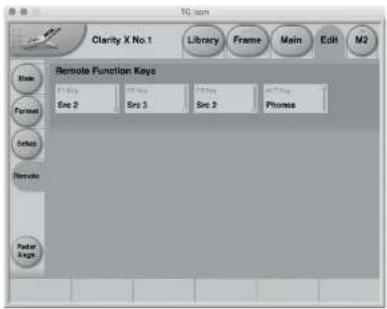
Fig. 78: Edit / Remote page
Remote Function Keys section
F1 Key to F3 Key parameters
Use these parameters to assign functions to the three Function keys (F1, F2 and F3) on the Remote control.
Available functions are:
Src2, Src3
Switch to the Source 2 or Source 3 module. Use this function to select another signal source.
Pressing the respective button again switches back to Src 1.
M1 Reset, M2 Reset, M1+M2 Reset
Reset Meter 1, Meter 2, or both Meters.
Dose Reset
Reset the Dose counter.
Set 2, Set 3, Phones setting
Switch to Speaker Set 2, Speaker Set 3 or Headphones. Pressing the respective button again switches back to Speaker Set 1.
Ref 2, Ref 3
Activate Reference Level 2 or Reference Level 3.
SL, SR
Mute and Solo the Side Left and Side Right speakers in a 7.1 setup. Along with the six dedicated Mute/Unmute/Solo buttons, this gives you full control over a 7.1 setup.
Downmix
Activate the multi-channel downmix feature (Downmix from 7.1 to Stereo).
You can configure the downconversion module on the Edit / Format page.
Mono
Convert the currently selected (Stereo, 5.1 or 7.1) Signal Source to Mono. For more information, see "Mono/Side section" on page 117.
Side
Hear the Side signal components for the currently selected Signal Source. For more information, see "Mono/Side section" on page 117.
NF Zoom
Activate the Noise Floor Zoom feature.
You can configure the Noise Floor Zoom feature on the Edit / Format page.
ALT key parameter
Set 2, Set 3, Phones setting
Switch to Speaker Set 2, Speaker Set 3 or Headphones. Pressing the ALT button again switches back to your main Speaker Set (1).
M2 - The LM8 Meter
Clarity X software version 1.3.00 – Build 3275 – Reference manual (updated 2016-10-18)
LM8 - introduction
M1 vs. M2
Clarity X has two high-end LM8 Radar meters.
The meters/meter set in the main monitoring engine are called M1. They always reflect what you are listening to.
In addition to this, Clarity X offers a dedicated metering engine with its own, independent routing called M2. This second LM8 instance will measure and display the channels you have selected for metering at all times regardless of whether you're listening to them or not. For more information on viewing and editing signal routings, see "Signal routing" on page 59.
For a signal flow overview, see "Clarity X signal flow diagram" on page 26.
The parameters for M1 and M2 are very similar, with some signal flow and user interface-related differences.
The current chapter ("M2 - The LM8 Meter") explains the basic concepts behind TC's Radar Meter and all M2 parameters.
For specific information about configuring M1, see "M1 Meter configuration" on page 149.
LM8 features
The LM8 Loudness Radar Meter algorithm shows the user the essence of the “loudness landscape” at a glance for a complete and instant overview, including:
▶ Loudness History
Momentary Loudness
True-peak Level
▶ Program Loudness and
▶ Loudness Range
- all this in a single view.
LM8 also features a detailed 24/7 logging function that will generate a text file which you can use to document adherence to a specific broadcast standard.
What is LM8?
LM8 represents a quantum leap away from simply measuring audio level to measuring perceived loudness.
The old level method is responsible for unacceptable level jumps in television, for music CDs getting increasingly distorted, and for different audio formats and program genres becoming incompatible: Pristine music tracks from the past don't coexist with new recordings, TV commercials don't fit drama, classical music or film and broadcast don't match. The most fundamental audio issue of all – control of loudness – makes millions of people adjust the volume control over and over again, every day.
LM8 is part of a universal and ITU-standardized loudness control concept, whereby audio may easily and consistently be measured and controlled at various stages of production and distribution.
LM8 works coherently together with other TC products, or with third-party equipment adhering to the same global standard. Follow the guidelines given to allow audio produced for different purposes to be mixed – without low dynamic range material (such as commercials or pop CDs) always emerging as the loudest.
LM8 core features
▶ Real-time loudness meter compliant with
EBU R128,
ATSC A/85.
TR-B32 and ITU-R BS.1770-3.
▶ Loudness History Radar display
▶ True-peak bar graph display
▶ Supports Mono, Stereo, 5.1 and 7.1
▶ Presets for use in broadcast, music, film and post production.
TC's Universal Database of Loudness
Since 1998, TC has performed listening tests and evaluation of loudness models. From these tests, TC has built an extensive Universal Database of loudness, based on tens of thousands of assessments. This database covers all sorts of broadcast material, music, commercials, feature film and experimental sounds, and is verified against other independent studies.
The Universal Database is authoritative from an academic as well as a practical point of view. It has been indispensable when designing the LM8 meter, because it provided the missing link between short-term and long-term loudness, and enabled the statistically founded Universal Descriptors of LM8.
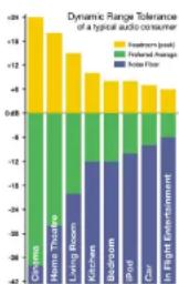
bar_stacked
Dynamic Range Tolerance of a typical audio consumer | Category | Feature Room (peak) | Folded Change | Noise Floor | |---|---|---|---| | Christmas | -18.0 | -6.0 | -2.0 | | Home Theatre | -17.0 | -5.0 | -2.0 | | Living Room | -13.0 | -4.0 | -2.0 | | Kitchen | -11.0 | -3.0 | -2.0 | | Bedroom | -9.0 | -2.0 | -2.0 | | Bird | -7.0 | -1.0 | -2.0 | | Car | -5.0 | 0.0 | -2.0 | | In Flight Entertainment | -3.0 | 1.0 | -2.0 |Fig. 79: Dynamic Range Tolerance (DRT) for consumers in different listening situations
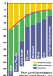
bar_line
Peak Level Normalization | Category | Inpatient Entertainment (%) | Preferred Average (%) | |---|---|---| | Cinema | -24 | -18 | | Home Theatre | -24 | -18 | | Living Room | -24 | -18 | | Kitchen | -24 | -18 | | Bedroom | -24 | -18 | | Pool | -24 | -18 | | Car | -24 | -18 | | In Flight Entertainment | -24 | -18 |Fig. 80: Peak level normalization
The chart of Dynamic Range Tolerance in Fig. 76 is a side-effect of the studies mentioned:
Consumers were found to have a distinct Dynamic Range Tolerance (DRT) specific to their listening environment. The DRT is defined as a Preferred Average window with a certain peak level Headroom above it. The average sound pressure level (which obviously is different from one listening condition to another) has to be kept within certain boundaries in order to maintain speech intelligibility, and to avoid music or effects from getting annoyingly loud or soft.
Audio engineers instinctively target a certain Dynamic Range Tolerance profile when mixing. But because level normalization in broadcast and music production is based on peak level measures, low dynamic range signatures end up the loudest as shown by the red line in Fig. 77. Peak level normalization means that material targeted at low dynamic ranges gets loud.
Audio production is therefore trapped in a downward spiral, going for ever decreasing dynamic
range. By now, the pop music industry is to the right of In-flight entertainment as shown in the illustration.
LM8 offers a standardized option. The visualization of loudness history and DRT – in combination with long-term descriptors from production onwards – is a transparent and well-sounding alternative to our current peak level obsession; not only for music, but also in production for broadcast or film.
An engineer – who may not be an audio expert – should be able to identify and consciously work with loudness developments within the limits of a target distribution platform – and with predictable results when the program is transcoded to another platform.
LM8 therefore color-codes loudness, making it easy to identify...
▶ target level (green),
▶ below-the-noise-floor level (blue) and
▶ loud events (yellow).
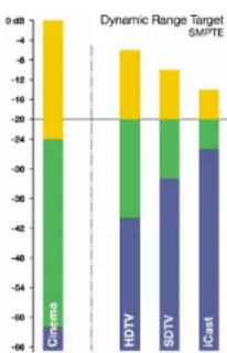
bar_stacked
Dynamic Range Target SMP/TE | Company | Segment 1 (%) | Segment 2 (%) | Segment 3 (%) | |---|---|---|---| | Cinems | -24 | -28 | -12 | | HDTV | -42 | -12 | -7 | | SDTV | -56 | -12 | -10 | | iCast | -24 | -12 | -10 |Fig. 81: Target loudness based on a consumer's Dynamic Range Tolerance
Fig. 78 shows target loudness for selected broadcast platforms based on a consumer's Dynamic Range Tolerance (DRT). The aim is to center dynamic range restriction around average loudness (in this case the -20 dB line), thereby avoiding washing out differences between foreground and background elements of a mix. Please note how different the broadcast requirements are from those of cinema.
When production engineers realize the boundaries they should generally stay within, less dynamics processing is automatically needed during distribution, and the requirement for maintaining time-consuming metadata at a broadcast station is minimized.
In broadcast, the goal is to use the same loudness measure for...
▶ Production,
Ingest,
▶ Linking,
▶ Master Control Processing and
▶ Logging.
Using the same loudness measure for all these purposes ensures better audio quality – not only in DTV audio, but across all broadcast platforms.
LM8 and TC processing can coexist with PPM meters, VU meters or Dolby's LM100 meter. L8 greatly increases the usability of LM100 in production environments because it provides running status, and gives a standardized and intuitive indication of both dialog and non-dialog program.
LM8 - Basic use and setup
LM8 can be used with mono, stereo, 5.1 and 7.1 material for any type of program material.
It visualizes...
▶ short-term loudness,
▶ loudness history and
long-term statistical descriptors.
To bring up the Radar display:
▶ Select the M2 page.
▶ Select the Radar subpage.
During normal operation, you will be using this page most of the time.
Reading the Radar display
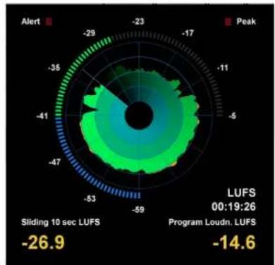
radar
| Metric | Value | |---|---| | Alert | -26.9 | | Peak | -14.6 | | Sliding 10 sec LUFS | -29 | | Program Loudn, LUFS | -17 | | LUFS 00:19:26 | -11 |Fig. 82: LM8 Radar
Target Loudness is displayed at the "12 o'clock" position of the outer LED ring, and at the radar circle marking the transition from green to yellow.
The yellow numbers in the lower part of the display are the two descriptors Loudness Range and Program Loudness.
For more information, see "LM8 Radar Page" on page 134. and "LM8 Main page" on page 137.
Pausing and resetting the Radar display
The Reset and Pause buttons to the left of the display are the "transport controls" of LM8. They are used to make the radar and descriptor measurements run, pause and reset.
Click the Reset button to reset the Radar display and the descriptors.
Setting up LM8
To change the name of the current LM8 Preset and adjust basic parameters, go to M2 / Main page. See "LM8 Main page" on page 137.
To configure what information the Radar view should display, go to M2 / Setup. See "LM8 Setup page" on page 141.
Working with LM8 presets
LM8 presets define parameters such as target loudness, noise floor, and overload conditions. You can use TC Icon's Library functions to re-name, store and recall presets – see "The Library: Recalling, storing and deleting settings" on page 91.
LM8 Radar Page
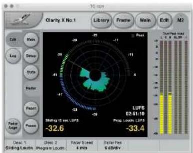
Fig. 83: LM8 Radar page
Outer Ring: Current Loudness
The segmented outer ring of the Radar page displays Momentary loudness. The "12 o'clock" position represents the 0 LU point (i.e. Target Loudness). Values above this point are shown in yellow. The "LU Reference" parameter can be found on the LM8 Main page.
The Low Level point is marked by the transition from green to blue. The "Low Level Below" parameter can be found on the Setup page.
The user should be instructed to keep the outer ring in the green area, and around the "12 o'clock" position on the average. Excursions into the blue or the yellow area should be balanced, and not only go in one direction.
The numbers associated with the outer ring may be referenced at either maximum loudness or have a zero point set at Target Level. You can set this on the Preferences page using the "Loudness Unit" parameter. Either way of looking at loudness is valid.
LUFS reading is in line with how peak level is typically measured in a digital system, and compatible with Dolby AC3 and E metadata, while the LU approach calls for a certain Target Loudness to have been predetermined, like e.g. a VU meter.
Long-term measurements
Universal descriptors may be used to make program-duration measurements, or you may "spot-check" regular dialog or individual scenes as required. It is recommended not to measure programs of a shorter duration than approximately 10 seconds, while the maximum duration may be 24 hours or longer.
Reset button
Before a new measurement, click the Reset button. This will reset the descriptors, the radar and the true-peak meters.
Run the audio, and watch the Radar and the descriptor fields update accordingly.
While the Radar will update instantly, the descriptors will wait five seconds into the program before showing the first readings. This is normal. Even though the first five seconds of a program are not shown instantly, they are included in the descriptor calculations.
LM8 incorporates an intelligent gate which discriminates between foreground and background material of a program. Consequently, measuring won't start before audio has been identified. The intelligent gate also pauses measurements during periods that only contain background noise, and during fade-outs of music tracks.
Universal Descriptors and Dolby LM100
Unlike methods that measure dialog only, LM8 may be used with any type of audio, including dialog.
If you wish to measure dialog, it is recommended to do a manual spot check of a program or a film. Find 10-30 seconds of regular dialog and measure it with LM8. Where dialog may be soft, regular or loud, and shift by more than 15 dB inside a film, regular dialog tends to be less ambiguous and more consistent across a program.
For compatibility with a proprietary measure such as Dolby LM100, only some of these meters are updated to use ITU-R BS.1770 and Leq(K) while others are locked at Leq(A). The software version of LM100 should be 1.3.1.5 or higher in order for it to comply with BS.1770, and to have its average loudness reading be compatible with Program Loudness in LM8.
Even used just on speech, Leq(A) is not a precise approximation to perceived loudness, so please update the unit to BS.1770 to obtain similar readings and predictable results.
To measure dialog with LM8 the same way Dolby LM100 is sometimes used, solo the Center channel during a spot check to momentarily disable the channel weighting specified in BS.1770, if you're working on a 5.1 stem.
Universal Descriptors and AC3 Metadata
The “Dialnorm” parameter in AC3 metadata should indicate the average loudness of a program. Basic dynamic range and level control that rely on this parameter may take place in the consumer's receiver. Therefore, its value should not be far off target, or the consumer results become highly unpredictable.
Program Loudness in LM8 is directly compatible with dialnorm in AC3. Most broadcast stations work with a fixed dialnorm setting, for instance -23 LUFS. This would be the Program Loudness target level for any program.
If your station is more music- than speech-oriented, better inter-channel leveling may be obtained with dialnorm permanently set 1 or 2 LU below the Program Loudness target level.
True-peak meters
The peak meters of LM8 display true-peak as specified in ITU-R BS.1770. True-peak meters give a better indication of headroom and risk of distortion in downstream equipment such as sample rate converters, data reduction systems and consumer electronics than digital sample meters used e.g. in CD mastering. Note that the standard level meters in most digital workstations and mixers are only sample peak (Final Cut, Avid, ProTools, Yamaha etc.) and should only be used as a rough headroom guideline.
Note that the meter scale is extended above 0 dBFS. Most consumer equipment distorts if you see readings above 0. It's not a problem to have true-peak level going to -1 dBFS in production, but legacy platforms (analog, NICAM etc.) and some data-reduction codecs may distort unless true-peak level is kept lower.
With Dolby AC3 and with low bit rate codecs, -3 dBFS should be considered the limit, while legacy platforms requiring emphasis may need even further restriction. As described in EBU R128, it is recommended to make full use of the headroom with true-peaks going to -1 dBFS in production, and to only restrict peak level further during distribution/transmission.
LM8 Main page
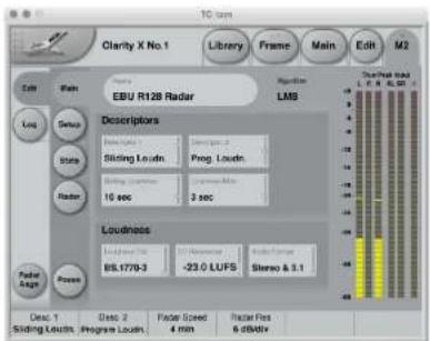
Fig. 84: LM8 Main page
Descriptors section
Descriptor 1 / Descriptor 2 parameters
Off setting
The respective descriptor will not be shown.
Range setting
Loudness Range (standardized in EBU R128 and abbreviated "LRA") displays the loudness range of a program, a film or a music track. The unit is LU, which can be thought of as "dB on the average".
The Loudness Range descriptor quantifies the variation of the loudness measurement of a program. It is based on the statistical distribution of loudness within a program, thereby excluding the extremes. Thus, for example, a single gun-shot is not able to bias the LRA number.
EBU R128 does not specify a maximum permitted LRA. R128 does, however, strongly encourage the use of LRA to determine if dynamic treatment of an audio signal is needed and to match the signal with the requirements of a particular transmission channel or platform.
Consequently, if a program has LRA measured at 10 LU, you would need to move the master fader ±5 dB to make loudness stay generally the same over the duration of the program (mot that you would want that).
In production, Loudness Range may serve as a guide to how well balancing has been performed, and if too much or too little compression has been applied. If a journalist or video editor isn't capable of arriving at a suitable LRA, he could be instructed to call an audio expert for help. The following may be regarded as initial production guidelines:
HDTV and digital radio:
Stay below LRA of 20 LU.
SDTV:
Stay below LRA of 12 LU.
▶ Mobile TV and car radio:
Stay below LRA of 8 LU.
Remember to use LRA the other way around, too: If there is an ideal for a certain genre, check its LRA measure, and don't try go below it. LRA should not be used for Limbo. Allow programs or music tracks the loudness range they need, but not more than they need.
Loudness Range may also be measured on a broadcast server to predict if a program is suitable for broadcast without further processing. LRA is even a fingerprint of a program and stays the same downstream of production if no dynamics processing has been applied. You may even check the number out of a consumer's set-top box to verify that distribution processing and Dolby DRC has been disabled.
As with Program Loudness and Loudness Max, the meter should be reset before measuring LRA.
Prog. Loudn. setting
Program Loudness returns one loudness number for an entire program, film or music track. Its unit is LUFS. Some vendors and countries use the unit "LKFS" or "LUFS", but all three designate the same: An absolute measure of loudness in the digital domain, where the region around "0" is overly loud and not relevant for measuring anything but test signals. Expect readings of broadcast programs in the range between -28 and -20 LUFS.
Program Loudness is used as a production guideline, for transparent normalizing of programs and commercials, and to set loudness metadata in delivery if so required.
For delivery or transmission of AC3 format, the metadata parameter “dialnorm” should reflect Program Loudness.
The easiest way to handle multiple broadcast platforms is to normalize programs at the station to a certain value, thereby being able to take advantage of the normalization benefits across platforms, at the same time enabling static metadata.
Loudness measurements in LM8 are all rooted in ITU-R BS.1770. However, subtle differences exist between different regions of the world. Therefore LM8 also includes the "Loudness Standard" parameter. Be sure to set this parameter correctly for compliance in your region.
The Program Loudness target is more or less the same for broadcasters around the world, espe-
cially when taking the measurement differences into account. Target numbers range between -24 and -22 LUFS.
As with Loudness Range and Loudness Max, the meter should be reset before measuring Program Loudness.
Sliding Loudness setting
Unlike Loudness Range, Program Loudness and Loudness Max, Sliding Loudness is a continuously updated measure that doesn't need to be reset. This type of descriptor is especially useful when "mixing by numbers" – i.e. when there is no access to the extremely informative radar display.
When mixing by numbers, having Program Loudness as one descriptor and Sliding Loudness as the other displays simultaneous information about the full program side by side with the most recent loudness history.
Because the Sliding Loudness measurement is completely ungated, it may also be used to spot-check sections of a program complying to "raw" ITU-R BS.1770 and the first revision of ATSC A/85.
LM8 makes use of optimized statistics processing in order to display a sliding loudness value (a prognosis) as quickly as possible after a reset.
Loudness Max setting
Loudness Max displays the maximum loudness registered since the meter was last reset. Loudness Max is an especially useful parameter when checking and normalizing short duration programs such as promos and commercials.
BCAP rules from the UK is an example of using Loudness Max as an efficient instrument to reduce listener complaints regarding loud commercials. While Program Loudness is adequate to normalize a consistent mix, Loudness Max may be used as a second line of transparent defense against overly short and loud event.
Sliding Loudness parameter
Use the Sliding Loudness parameter to define the time window that is used for Sliding Loudness measurements.
For more information, see "Sliding Loudness setting" on page 138.
The selected Sliding Loudness setting is also displayed on the Statistics page, e.g. as "Sliding Loudness 10 sec".
For more information, see "LM8 Statistics page" on page 143.
Loudness Max parameter
Use the Loudness Max parameter to define the time window that is used for Loudness Max measurements.
For more information, see "Loudness Max setting" on page 139.
The selected Loudness Max setting is also displayed on the Statistics page, e.g. as "Loudness Max 3 sec".
For more information, see "LM8 Statistics page" on page 143.
Loudness section
Loudness Std. parameter
The Program Loudness measure is always rooted in the ITU-R BS.1770 loudness model. This parameter sets measurement gating. Note that the parameter only influences Program Loudness, and not Sliding Loudness or Loudness Max.
BS.1770-3 setting
This setting reflects the latest revision of ITU-R BS.1770. Relative gate at -10 LU, safety gate at -70 LUFS.
Leq(K) setting
This setting reflects the original version of ITU-R BS.1770. No measurement gate besides from at safety gate at -70 LUFS, so the user doesn't need to precisely start and stop a measurement in order to avoid bias from complete silence.
Center of Gravity setting
The standard setting from early versions of TC radar meters. Relative gate at -20 LU, safety gate at -70 LUFS.
LU Reference parameter
The LU Reference parameter defines the loudness required to obtain a "12 o'clock" reading on the outer ring of the Radar display, which is the same as the border between green and yellow on the Radar.
Audio Format parameter
Use the Audio Format parameter to specify the format of the metered signal. Choose between Stereo & 5.1 and 7.1. The True-Peak Input Meter (if shown) will change accordingly.
LM8 Setup page
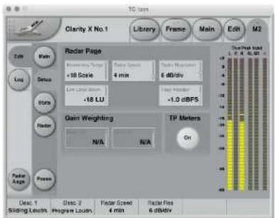
Fig. 85: LM8 Setup page
Radar page section
Momentary Range parameter
Settings: "+9 Scale" or "+18 Scale"
EBU mode meters can display two different momentary displays:
+9 Scale setting
The +9 Scale setting provides a narrow loudness range intended for normal broadcast. It gives a momentary meter range from -18 to +9 LU.
+18 Scale setting
The +18 Scale setting provides a wide loudness range intended for film, drama and wide range music. The It gives a momentary range from -36 to 18 LU.
Radar Speed parameter
Range: 1 minute to 24 hours
The Radar Speed parameter controls how long each revolution of the Radar display takes. You may "zoom" between the settings during run-time, as long as the history isn't reset.
Pressing the Reset button on the Radar page will reset meter and descriptor history.
Radar Resolution parameter
Range: 3 to 12 dB/div
The Radar Resolution parameter sets the difference in loudness between each concentric circle in the Radar display. Choose a low value when targeting a platform with a low dynamic range tolerance. You may "zoom" between the settings, as long as the history isn't reset.
Low Level Below parameter
Range: -30 to -6 LU
The Low Level Below parameter determines where the transition between the green and blue range occurs in the outer ring. It indicates to the engineer that the signal level is now at risk of being below the noise floor.
Peak Indicator parameter
Range: -12 to +3 dBTP
Use the Peak Indicator parameter to specify the value that should trigger the Peak indicator in the upper right corner of the Radar display. E.g., if you set Peak Indicator to -1 dBFS, the PEAK indicator on the Radar page will be lit when the signal is -1 dBFS or above.
7.1 Gain Weighting section
Please note that the parameters in the 7.1 Gain Weighting section are only available when the Audi Format parameter on the LM8 Main page has been set to 7.1. For more information, see "Audio Format parameter" on page 140.
Back L/R parameter
When the LM8 Radar meter is being used for metering Stereo and 5.1 signal sources, the way that each channel's gain is taken into consideration is well-defined. However, when metering 7.1 format signals, no standards apply. In this case, use the Back L/R parameter for weighting the Back Left and Back Right channels.
Side L/R parameter
When metering a 7.1 format signal, use the Side L/R parameter for weighting the Side Left and Side Right channels. For more information, see "Back L/R parameter" on page 142.
True Peak Meters section
(True Peak Meters) On parameter
Use the On button to switch the True Peak meters on the right edge of the LM8 user interface on or off.
To set the format for the True Peak Meters, use the Audio Format parameter on the LM8 Main page.
LM8 Statistics page
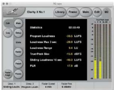
Fig. 86: LM8 Statistics page
The Statistics page gives an overview of essential descriptors:
Program Loudness
▶ Loudness Max
▶ Loudness Range
True-Peak Max
▶ Sliding Loudness
PLR (Peak to Loudness Ratio)
About PLR (Peak to Loudness Ratio)
PLR (Peak to Loudness Ratio) measurements often correlate with audio quality – be careful not to force it too low. Programs and tracks should be allowed to live.
! Important: Clicking the Reset button will reset the meters and the log file.
LM8 log files
Loudness meter data is stored in the device's internal memory and can be transferred to a computer using the TC Icon application (but not with the hardware TC Icon).
! Please note that while both Clarity X LM8 meters (M1 and M2) are logged internally, file handling functions as described in this section are only available for M2.
However, M1 can be logged using the Auto Logging feature. For more information, see "Auto Logging" on page 147.
Log file resets
The meter log file is reset (along with the actual Loudness Meter)...
▶ when you turn off the device
▶ when the Meter is reset manually.
The log file is also reset along with the Loudness Meter if the measurement standard is changed manually, or by loading a preset based on a different standard.
Log page
To access the log file-related functions, select your TC HD device/Frame in TC Icon software, switch to the tab of the respective loudness meter and select the "Log" page button on the left side of the main window.
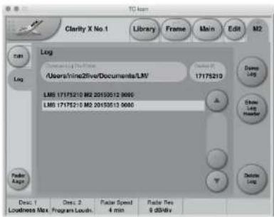
Fig. 87: Log page with two log files
Common Log File Folder
Use the Common Log File Folder field to specify a folder on your computer where retrieved log files should be stored.
The folder you set here is a common folder for all the products controlled from this particular TC Icon software.
Log File folder defaults
The default log file folder for Microsoft
Windows is:
[C:] \users\ [your user name] \Documents\LM
The default log file folder for Apple OS X is:
[Root] /users/ [your user name] /
Documents/TC Electronic/
To specify the folder path, click in this field and type the path to the folder you want to use. Press the Enter key to confirm.
Dump log button
This button is not available when Auto Logging has been enabled – see "Auto Logging" on page 147.
Click the Dump Log button to manually retrieve the log file from the selected device and Engine and store it on your computer in the Common Log File Folder.
You will be asked to confirm this operation, as the TC Icon software user interface will not be available during log file retrieval.
Show Log Header button
This button is not available when Auto Logging has been enabled – see "Auto Logging" on page 147.
Select a log file from the log file list and click the Show Log Header button to show its header information (see "Log file header" on page 146.
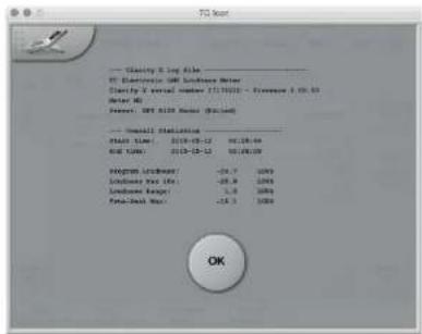
Fig. 88: Clarity X log file header
Delete Log button
This button is not available when Auto Logging has been enabled – see "Auto Logging" on page 147.
To delete a log file from your computer's hard disk, select the respective log file from the log file list and click the Delete Log button. You will be asked to confirm this operation.
Device ID field
The Device ID is used for naming log files. This applies to both manually and automatically retrieved log files.
If you operate several TC HD devices, use the Device ID field to give each device a unique name. This might be the name of the TV channel being measured with this device. By default, the Device ID corresponds to the product serial number.
Additional information when Auto Logging is enabled
To learn how to set up Auto Logging, see "Auto Logging" on page 147.
When Auto Logging is enabled for this Engine, the following information will be displayed on the Log page:
Next log retrieval
This field will display a countdown to the next log file retrieval (e.g. as "35 min. 54 sec.") or show "Now" while retrieving a log file.
Last log
After successful log file retrieval, the path to the file is shown plus the file header with statistics summary.
Log file format and structure
Each log file is a plain text file with the structure shown below. The header shows a summary of the log, followed by the actual, time-stamped values in tab-separated values format.
This file format can easily be imported into spreadsheet applications such as Microsoft Excel or Apple Numbers for further analysis.
Log file header
If the Loudness Meter preset being used has been edited, the Preset Name is followed by "Edited". The serial number, preset name and software version information for the logged device is also available.
The summary includes statistics, and the measurements are stored every second.
Time and date is added while dumping the log file. This information is derived from the computer that the TC Icon software is running on. Accordingly, you need to ensure that the computer's clock is set correctly.
Log file name
The log file's name is composed from the Algorithm, the Device ID, the Meter Engine, the date (coming from the computer running the TC Icon software), plus a number starting with 0000 and increased for each log file retrieval on the same date.
Log file example
Header lines are indicated by a leading hash character.
# --- Clarity X log file ----
#
# TC Electronic LM8 Loudness Meter
# Clarity X serial number 17175210 - Firmware
0.09.00
# Meter M2
# Preset: EBU R128 Radar (Edited)
#
# --- Overall Statistics ----
#
# Start time: 2015-05-13 23:13:49
# End time: 2015-05-13 23:35:10
#
# Program Loudness: -120.0 LUFS
# Loudness Max 10s: -59.6 LUFS
# Loudness Range: 0.0 LUFS
# True-Peak Max: -23.2 LUFS
# --- Loudness log ----
#
DateTimeLoudness(LUFS)
2015-05-13 23:13:49 -59.63
2015-05-13 23:13:50 -59.63
2015-05-13 23:13:51 -59.63
2015-05-13 23:13:52 -102.59
etc.
Working with log files
You can delete, move and rename log files as required using Windows Explorer in Microsoft Windows, the Finder in OS X or a third-party file manager.
Auto Logging
Using the free TC Icon software application (but not the hardware TC Icon), it is possible to specify a fixed interval at which the computer will collect Loudness Meter log files from the Frames controlled by the Icon software.
Log file retrieval can be activated for a wide range of TC Electronic devices from TC Icon software.
! Please note that when enabled, auto logging will work for both LM8 meters (M1 and M2), and the log files are saved in the same folder.
Log Select page
To activate Auto Logging,
- switch TC Icon software to Base mode by clicking the Icon symbol in the upper left corner of the window,
▶ click the Auto tab on top of the window
- click the Log Select page button on the left side of the window.
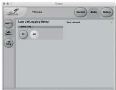
Fig. 89: Auto Logging – Log Select page, with meter M2 enabled for logging
Use this page to select the Frame(s) and Engines in that Frame from which you want to collect log files. Engines enabled for logging will be highlighted.
Button "LED" states
Grey
Indicates that this Engine holds a valid LM8 algorithm, but no log file has been retrieved yet.
Green
Indicates that at least one log file has been retrieved from this Engine.
Yellow
Indicates that this Engine does not hold an LM8 algorithm.
Red
Indicates that there was a problem retrieving the log file. Check that the connection to the Frame is working.
Blue - blinking
Indicates that the log file is currently being retrieved from the specific Frame and Engine.
"Auto log is not available from this device"
If a product controlled by the Icon application does not feature a Loudness Meter.
Log Setup page
To configure Auto Logging,
- switch TC Icon software to Base mode by clicking the Icon symbol in the upper left corner of the window,
▶ click the Auto tab on top of the window
- click the Log Setup page button on the left side of the window.
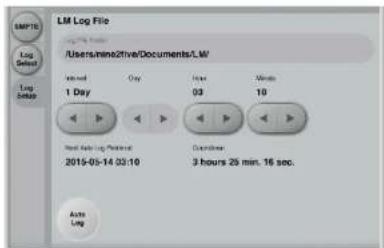
Fig. 90: Auto Logging - Log Setup page
Use the parameters on this page to set up log file retrieval.
Auto log button
Click this button to enable Auto Logging for all devices/Engines that have the respective Meter button enabled on the Log Select page – see "Log Select page" on page 147.
Log File Folder
Use the Log File Folder field to specify a folder on your computer where retrieved log files should be stored.
The folder you set here is a common folder for all the products controlled from this particular TC Icon software.
Log File folder defaults
The default log file folder for Microsoft Windows is: [C:] \users\ [your user name] \Documents\LM
The default log file folder for Apple OS X is: [Root] /users/ [your user name] / Documents/TC Electronic/
Interval field
Settings: 1 / 2 / 4 / 12 hours, 1 day, 1 week Use the arrow buttons in this section to define the interval for log file retrieval.
Day / Hour / Minute fields
Use the Hour and Minute fields to set a specific time of day when the next log file should be retrieved. The clock is set in 24 hours format.
Additional log files will be retrieved in the intervals specified using the Interval field.
E.g., if you set the Hour and Minute fields to 2 hours and 10 minutes and set the Interval field to 4 hours, log files will be retrieved at 2:10 am, 6:10 am, 10:10 am etc.
When you have set the Interval field to "1 Week", you can also set the day of the week when the log file should be retrieved.
For devices running 24/7, you would usually chose a time when log file retrieval does not interfere with other activities.
E.g., you could retrieve the log file every Monday at 01:05.
Once you have activated Auto Logging, additional information is displayed on the Log Setup page:
Next Auto Log Retrieval display
This is the time when the next log file retrieval will occur.
E.g., "2014-09-15 15:57" means that the next log file retrieval will occur on September 15, 2014, at 3:57 pm.
Countdown display
This field shows a countdown to the next log file retrieval in hours, minutes and seconds.
Retrieving Log From display
The name of the device and the Engine from which a log file is currently being retrieved, e.g. "7: Loudness Pilot No.87 - M2"
M1 Meter configuration
Clarity X software version 1.3.00 – Build 3275 – Reference manual (updated 2016-10-18)
M1 - introduction
The differences between the two Radar Meter instances M1 and M2 are explained in "M1 vs. M2" on page 129.
The parameters for M1 and M2 are very similar, with some signal flow and user interface-related differences.
For a full explanation of the concepts behind TC's Radar Meter and all M2 parameters, see "M2 – The LM8 Meter" on page 128.
In the current chapter ("M1 Meter configuration"), we will refer/link to the relevant parameter descriptions in the M2 chapter.
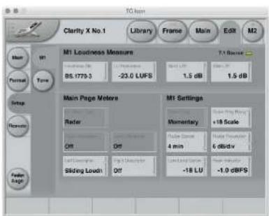
Fig. 91: Edit - Setup - M1 page
M1 Loudness Measure section
Loudness Std parameter
For more information, see "Loudness Std. parameter" on page 139.
LU Reference parameter
For more information, see "LU Reference parameter" on page 140.
Back L/R parameter
For more information, see "Back L/R parameter" on page 142.
Side L/R parameter
For more information, see "Side L/R parameter" on page 142.
Main Page Meters section
M1 Meter Type parameter
Use the M1 Meter Type parameter to specify the meter that should be displayed on the Clarity X main page.
In the software version described in this manual, this parameter is not editable.
Upper Bargraph parameter
Use the Upper Bargraph parameter to specify the meter that should be in the Upper Bargraph Section of the Clarity X main page's left pane.
In the software version described in this manual, this parameter is not editable.
Lower Bargraph parameter
Use the Lower Bargraph parameter to specify the meter that should be in the Lower Bargraph Section of the Clarity X main page's left pane.
In the software version described in this manual, this parameter is not editable.
Left Descriptor / Right
Descriptor parameters
For more information, see "Descriptor 1 / Descriptor 2 parameters" on page 137.
M1 Settings section
Outer Ring parameter
For more information, see "Outer Ring: Current Loudness" on page 134.
Outer Ring Range parameter
For more information, see "Momentary Range parameter" on page 141.
Radar Speed parameter
For more information, see "Radar Speed parameter" on page 141.
Radar Resolution parameter
For more information, see "Radar Resolution parameter" on page 141.
Low Level below parameter
For more information, see "Low Level Below parameter" on page 141.
Peak Indicator parameter
For more information, see "Peak Indicator parameter" on page 142.
Preferences
Clarity X software version 1.3.00 – Build 3275 – Reference manual (updated 2016-10-18)
Preferences page
Use the parameters on the Frame / System / Prefs page to configure basic measurements units and other parameters that usually only need to be set up once.
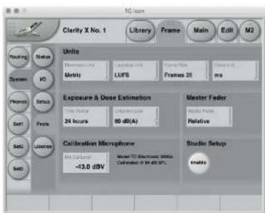
Fig. 92: Preferences page
Units Section
Dimension Unit parameter
Settings: Metric, Feet
Use the Dimension Unit parameter to select the unit for all dimensional parameters and displays.
Setting the Dimension Unit parameter to Metric will switch the Temperature indicator on the Frame / System page to degrees Celsius.
Setting the Dimension Unit parameter to Feet will switch the Temperature indicator on the Frame / System page to degrees Fahrenheit.
Loudness Unit parameter
LUFS setting
All measurements of program loudness and sliding loudness are shown in units of LUFS – that is, in Loudness Units on the absolute scale. This is the normal setting for the Loudness Unit parameter, which we recommend for most applications.
Loudness Range is always shown in units of LU, because it is basically a measurement of 'range' or of the distance between a high and a low loudness level.
LU setting
With this setting, measurements of program loudness and sliding loudness are shown in units of LU – that is, in Loudness Units on a relative scale. The 0 LU is by definition the target loud-
ness level, such as -23.0 LUFS. So by selecting "LU", one can immediately see if a loudness level is above the target level (e.g. +1.2 LU) or below (e.g. -3.4 LU).
Frame Rate parameter
Settings: 24, 25, 30, 50, 60 frames
Where parameters such as the Monitor Out Delay parameter are defined using Frames, you need to establish the frame rate. Use the Frame Rate parameter for this.
Delay Unit parameter
Settings: ms, Frames
Use the Delay Unit parameter to set the unit for all time-based parameters.
! If you use the Frame setting, you will also need to define the correct video frame rate on the Preferences page. For more information, see "Frame Rate parameter" on page 153.
Exposure & dose estimation section
Use the parameters in this section to configure the Dose meter.
For more information, see “Hearing loss protection” on page 24 and “Dose Metering” on page 119.
Time Period parameter
Settings: 24 hours, One week
Use the Time Period parameter to set the time frame that dose measurements should be based on.
Setting this parameter to 24 hours means that all sound listened to via Clarity X during the past 24 hours is accumulated into sound exposure. The displayed Sound Exposure Level (SEL) is scaled to a normalized 8 hour day, making the value comparable to nominal working day recommendations. In a similar fashion, "One week" accumulates sound for the most recent seven days, with SEL for a standard work week of 40 hours.
al audio content of your input source and the level you're listening at. This is made possible by having calibrated your loudspeakers and headphones. However, the estimate provided by Clarity X should be used as a guideline. It will be more accurate if the loudspeakers and acoustics of your studio are not coloring the sound, and if your headphones are voiced to mimic what your ears receive from a set of loudspeakers.
Master Fader section
Master Fader parameter
Settings: Absolute, Relative
Use the Master Level parameter to define whether the Master Level on the right pane of the Main page should be displayed
▶ as an absolute dB value or
- in relation to the Reference Level (where e.g. -6 dB means "6 dB below the Reference Level").
! For the Master Level display to be shown as an absolute value, the respective Speaker Setup has to be calibrated and defined as Ready.
! Phone Levels are always shown relative, as headphones cannot be calibrated.
Criterion Level parameter
Range: 77 to 88 dB
Use the Criterion Level parameter to define the sound exposure level that should be used as the basis for Dose % measurements. A higher criterion level means a less conservative Dose % measure.
! Clarity X continually estimates the SPL, Sound Exposure Level and Dose, based on the actu-
Calibration Microphone section
Microphone calibration level display Clarity X comes with a factory-calibrated, phantom power enabled microphone input dedicated for speaker system calibration and measurements using the included TC Electronic 3600A Reference Microphone. The microphone is calibrated at the factory with 94 dB SPL, and the resulting output voltage - e.g. -42.7 dBV - is noted on the calibration label on the microphone along with the date of calibration.

This value should be entered as the Mic Cal Level. As each microphone and a Clarity X unit are paired at the factory, the calibration value for that particular microphone is already stored in the unit as the default value. If future calibrations are made, the resulting level can be entered using the Mic Cal Level parameter.
The microphone is carefully calibrated at the factory and paired with a specific Clarity X that is calibrated accordingly – but physical factors such as static pressure, humidity and temperature may affect the precision. For maximum precision, consider using an IEC/EN 60942 Class 1 acoustic calibrator for recalibrating the Clarity X with the reference microphone.
! The Mic Cal Level is reset when Reset To Defaults on the Frame / System / Setup / Version is used.
Note: Should you need to replace your microphone (or by mistake swap it with another microphone of the same type), make sure the correct microphone calibration value is entered using the Icon application.
Studio Setup section
Studio Setup Enable button
To use Speaker Setups, activate the Studio Setup button.
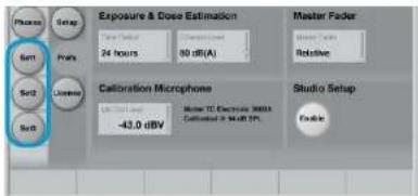
Fig. 93: Studio Setup active – Speaker Sets enabled
When Studio Setup is enabled, buttons for three "Set" pages (Set1, Set2, Set3) will be shown under the Frame tab, which can be configured individually. For more information, see "Speaker Set configuration" on page 66.
Working with Studio Setups disabled has several important implications/consequences.
▶ You will not be able to edit/modify Studio Set-ups.
▶ You will not be able to store Studio Setups using the Library / Store page. However, you will be able to recall previously defined Studio Presets.
▶ You will not able to change output assignments on the Frame / Routing page.
Clarity X firmware update and Device Reset
Clarity X software version 1.3.00 - Build 3275 - Reference manual (updated 2016-10-18)
You should keep both the TC Icon software running on your computer and the software of your Clarity X (the firmware) up to date. Using up-to-date software versions ensures you benefit from bug fixes and the latest features.
Updating the firmware of your Clarity X requires a computer with the TC Icon software installed.
In TC Icon, you can select a previously downloaded Clarity X firmware file (with a ".tca" suffix) and apply it to the currently selected Clarity X.
For downloading, installing and updating TC Icon software, please refer to
▶ "Finding and installing TC Icon software – Microsoft Windows" on page 18 or
- "Finding and installing TC Icon software - OS X" on page 20.
This section describes downloading and installing the Clarity X firmware.
Finding and installing Clarity X firmware – Microsoft Windows
You can download the latest version of the Clarity X firmware from:
tcelectronic.com/support/software/
On this page, locate the "Clarity X" section.
In this section of the support page, look for "Firmware" and click the button representing the latest version of the Clarity X firmware.

Clarity X
Firmware
+ Show version history


Clarity X Firmware Windows & Mac - Version 1.1 - 1.24 MB
Released: Wednesday, July 1, 2015
TC Icon Software
+ Show version history

Clarity X TC Icon Software Windows - version 8.1 - 1.8 Mb
Released: Wednesday, July 1, 2015

Clarity X TC Icon Software Mac - Version 8.1 - 5.72 MB
Released: Wednesday, July 1, 2015

Clarity X TC Icon Software Version 8.1 - 1.79 MB
Released: Wednesday, July 1, 2015
Fig. 94: Clarity X software on the TC Electronic software download page
Depending on your browser type and configuration, a dialog may be shown asking you what you want to do with this file.
Choose "Save".
The software will be downloaded to your browser's default download location. Usually, this is the "Downloads" folder for your user account.
▶ In Windows Explorer, navigate to the folder containing the ZIP file you just downloaded.
- Right-click the ZIP file and choose "Extract All..." from the context menu.
A dialog box will allow you to specify where the extracted files should be stored.
Accept the defaults or change the path. We suggest changing the path to "C:\TCUPDATE\". This will allow you to locate the file in TC Icon software more easily.
After extracting the ZIP file, you will see a .tca file in Windows Explorer.
In the next steps, you will select this .tca file in the TC Icon software to transfer it to Clarity X. We will assume that you have extracted the content of the ZIP archive to C:\TCUPDATE.
If you have extracted it to another location, you will have to specify this in the "Common Software Update Folder" field accordingly (see below).
- Connect your PC to the Clarity X that you want to update using an Ethernet cable.
▶ Launch the TC Icon software on your PC.
▶ In the TC Icon software, select the Clarity X that you want to update. - Go to the Frame / System / Setup / Version page.
Here, you will find the current software version of your Clarity X (shown as "Clarity X SW Version"). Note this version number.
▶ Go to the Frame / System / Setup / Update page.
- Click into the "Common Software Update Folder" field.
▶ Enter the path to the folder where the downloaded .tca file is located.
Example:
Assuming that...
▶ your hard disk drive has the letter c:\
you extracted the downloaded .tca file to the folder "TCUPDATE" on the drive root (see previous steps)
...the correct path would be:
C:\TCUPDATE\
▶ Click Enter. You will be returned to the previous screen.
The name of the .tca file you downloaded should now be displayed right under the "Common Software Update Folder" field.
If you want to make sure you have selected the correct file before applying the update, you can select the downloaded software file and click the "File Info" button to display additional information.
▶ To apply the update, select the downloaded .tca file and click the "Update SW" button.
▶ Confirm that you want to perform the update by clicking the "Yes" button.
A confirmation message will be shown once the update has been applied.
Click "OK".
▶ Go to the Frame / System / Setup / Version page and note the updated software version.
! Please note that a folder may contain multiple .tca files, which will be shown on the Frame / System / Setup / Update page when that folder is selected. Be sure to select the correct file – usually, the most current one.
! If you experience technical problems during software download or installation, please ask a person with administrator privileges on this PC for assistance.
Finding and installing Clarity X firmware - OS X
You can download the latest version of the Clarity X firmware from:
tcelectronic.com/support/software/
On this page, locate the "Clarity X" section.

Clarity X
Firmware
+ Show version history


Clarity X Firmware Windows & Mac - Version 1.1 - 1.24 M3
Released: Wednesday, July 1, 2015
TC Icon Software
+ Show version history

Clarity X TC Icon Software Windows - version 8.1 - 1.8 Ma
Released: Wednesday, July 1, 2015

Clarity X TC Icon Software Mac Version 8.1 - 5.72 MB
Released: Wednesday, July 1, 2015

Clarity X TC Icon Software Version B1.1.20MP
Released: Wednesday, July 1, 2015
Fig. 95: Clarity X software on the TC Electronic software download page
In this section of the support page, look for "Firmware" and click the button representing the latest version of the Clarity X firmware.
Depending on your browser type and configuration, a dialog may be shown asking you what you want to do with this file. Choose "Save".
The software will be downloaded to your browser's default download location. Usually, this is the "Downloads" folder for your user account.
- Go to the folder containing the file you just downloaded.
If you are seeing a .ZIP file, double-click it to extract its contents. However, your browser may already have extracted the contents from the .ZIP file automatically.
After the ZIP file has been extracted, you will see a .tca file in the Finder.
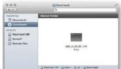
Fig. 96: Clarity X software (.tca) in the OS X Finder
In the next steps, you will select this .tca file in the TC Icon software to transfer it to Clarity X.
For the first example, we will assume that you have left the file at its default position (the "Downloads" folder).
If you have moved the downloaded .tca file somewhere else, or if you intend to use a .tca file on a network or USB drive, you will have to specify the correct path in the "Common Software Update Folder" field of TC Icon software accordingly (see "Locating the Clarity X firmware file – example 2" on page 162).
- Connect your Mac to the Clarity X that you want to update using an Ethernet cable.
▶ Launch the TC Icon software on your Mac.
▶ In the TC Icon software, select the Clarity X that you want to update.
▶ Go to the Frame / System / Setup / Version page.
Here, you will find the current software version of your Clarity X (shown as "Clarity X SW Version"). Note this version number.
- Go to the Frame / System / Setup / Update page.
- Click into the "Common Software Update Folder" field.
Enter the path to the folder where the downloaded .tca file is located.
Locating and transferring the Clarity X firmware file – example 1
This is a simple default scenario where we assume that...
▶ your hard disk drive is called "Macintosh HD"
▶ your (short) user account name in OS X is "joe" and
▶ you have not moved the .tca file from its download location.
In this case, the correct path to enter in the "Common Software Update Folder" field is:
/ users / joe / downloads/
▶ Click Enter. You will be returned to the previous screen.
The name of the .tca file you downloaded should now be displayed right under the "Common Software Update Folder" field.
If you want to make sure you have selected the correct file before applying the update, you can select the downloaded software file and click the "File Info" button to display additional information.
▶ To apply the update, select the downloaded .tca file and click the "Update SW" button.
▶ Confirm that you want to perform the update by clicking the "Yes" button.
A confirmation message will be shown once the update has been applied.
Click "OK".
Go to the Frame / System / Setup / Version page and note the updated software version.
Locating the Clarity X firmware file – example 2
If you have moved the .tca file to a folder called "Updates" on an external hard disk called "DAW2", the correct path to enter in "Common Software Update Folder" would be:
// Volumes / DAW2 / Updates /
For the remaining steps, see Example 1.
! Please note that a folder may contain multiple .tca files, which will be shown on the Frame / System / Setup / Update page when that folder is selected. Be sure to select the correct file – usually, the most current one.
! If you experience technical problems during software download or installation, please ask a person with administrator privileges on this Mac for assistance.
Resetting your Clarity X
If you need to reset Clarity X, use the Reset button on the Frame / System / Setup / Version page.
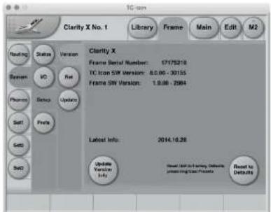
Fig. 97: Reset to Defaults button on the Frame / System / Setup / Version page
! The Reset procedure will reset all System, Studio and Project settings to factory defaults. This includes the microphone calibration value so any changes you may have made will be lost. However, your User Presets will not be deleted.
As the IP address will be reset as well, you may have to check and update network settings after a Reset. For more information, see "Networking basics and troubleshooting" on page 39.
You will be asked to confirm this procedure.
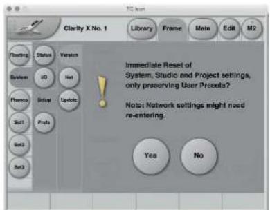
Fig. 98: Reset to Defaults confirmation dialog
TC Icon Setup
Clarity X software version 1.3.00 – Build 3275 – Reference manual (updated 2016-10-18)
This chapter covers screens and parameters of the TC Icon software not directly related to the day-to-day operation of your Clarity X.
Accessing the Icon Setup pages
If it isn't already, switch the Icon software to Base mode by clicking the Icon symbol in the upper left corner of the window - see "TC Icon modes: Base and Device operation" on page 47.
In Base Mode, you will see the Select, Auto and Setup tabs on the upper edge of the TC Icon window.
▶ Select Setup.
▶ Select one of the pages described in the following sections of this manual.
Info page
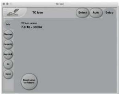
Fig. 99: Setup - Info page
On this page, the version number of the currently installed TC Icon software is displayed.
To update the TC Icon software, please refer to the "Keeping your Clarity X up-to-date" on page 44 section of this manual.
Devices page
Use this page to detect, control and assign the devices in your local network.
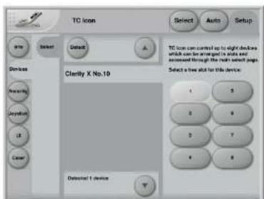
Fig. 100: Setup - Devices page
Detect button
Click the "Detect" button to scan the network for connected devices. All detected devices will appear in the list.
If you encounter problems when detecting connected devices, please refer to "Networking basics and troubleshooting" on page 39.
Assigning devices to the available slots
You need to assign a device to a slot of the TC Icon software to control it. Each instance of the TC Icon software can control up to eight different devices.
Select a device from the list on the left side of the screen.
Click one of the eight slots on the right side of the screen to assign the selected device to this slot.
Security page
On the security page, you can set several features regarding device readouts and operation.
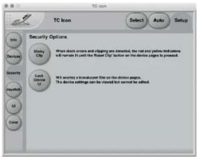
Fig. 101: Setup - Security page
Sticky Clip button
Click the Sticky Clip button to activate or deactivate the Sticky Clip feature.
When the Sticky Clip feature is activated (button highlighted) and clock errors or clippings are detected in a device, the red and yellow warning indicators will remain lit until the user presses "Reset Clip" button. This feature ensures that clock errors or clippings do not go unnoticed.
Lock Device UI button
Click the Lock Device UI button to lock or unlock the user interfaces of the devices controlled by the TC Icon software.
When the Lock Device UI feature is activated (button highlighted), the user will be able to see the settings of the currently selected device, but he cannot change them. This will be indicated by a semi-transparent overlay and a "Device UI is locked" message on all device-related screens.
Fig. 102: Device UI locked
Joystick page
The MIDI Joystick setup page of the TC Icon software is not required for operating Clarity X and is not described in this manual.
UI (user interface) page
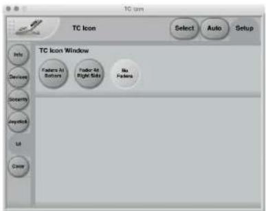
Fig. 103: Setup - UI page
TC Icon Window parameter
Use the TC Icon Window parameter to specify if and where faders should be shown. Three options are available. Changes on this page will take effect next time you open the TC Icon software.
Faders at bottom setting
Faders will be positioned right below the main interface. This is the default setting.
Fader at right side setting
One fader will be positioned to the right of the main interface.
No faders setting
No faders will be shown on screen.
Color page
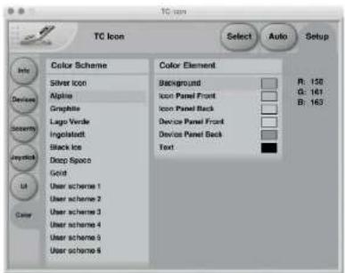
Fig. 104: Setup - Color page
Use the parameters on the Color page to define the TC Icon software's interface colors.
Color Scheme parameter
Use the Color Scheme parameter to select a predefined color scheme. You can select a predefined color scheme from the list or define your own color scheme using one of the "User scheme" slots.
Color Element parameters
Use the Color Element parameters to customize the colors of the currently selected User scheme. You can change the colors used for:
Background
▶ Icon Panel Front
▶ Icon Panel Back
▶ Device Panel Front
▶ Device Panel Back
▶ User Interface Text.
We suggest changing these colors under realistic/typical lighting conditions to make sure the interface is readable during day-to-day use.
Changing User scheme colors
To change the color, select a user interface component in the Color Element list (e.g. Background) and set the three R(ed) G(reen) B(lue) faders to the desired values.
To apply the new color scheme, click the "Apply User Scheme" button.
Appendix 1: Links and additional information
Clarity X software version 1.3.00 - Build 3275 - Reference manual (updated 2016-10-18)
Support resources
▶ TC Electronic service and warranty: tcelectronic.com/support/service-warranty/
▶ TC Electronic Support: tcelectronic.com/support/
TC Electronic – product software: tcelectronic.com/support/software/
TC Electronic – all product manuals: tcelectronic.com/support/manuals/
▶ TC Electronic user forum: forum.tcelectronic.com/
TC Electronic on...
▶ the web: tcelectronic.com/
▶ Facebook: facebook.com/tcelectronic
▶ Google Plus:
plus.google.com/+tcelectronic/
▶ Twitter:
twitter.com/tcelectronic
▶ YouTube: youtube.com/user/tcelectronic
TC HD resources
▶ TC Electronic | Production: tcelectronic.com/production/
▶ TC Electronic | Broadcast: tcelectronic.com/broadcast/
▶ TC HD products on YouTube: youtube.com/user/tcelectronicHDaudio/
Product-related information
▶ Clarity X product information page: tcelectronic.com/clarity-x/

tc electronic
Appendix 2: Acoustics
Appendix 2: Acoustics
Clarity X software version 1.3.00 – Build 3275 – Reference manual (updated 2016-10-18)

tc electronic
Appendix 2: Acoustics
Introduction
When we talk about making a room "sound right", we are usually dealing with room acoustics.
As a science, acoustics has been around for about a hundred years. Until then, good acoustics happened by experiment, by experience, or simply by accident. Today, we know a lot more about the parameters that influence the "sound" of a room.
A control room should basically act as neutral as possible. But this is not always the case. Let's take a look on some of the issues that we need to be aware of.
Good acoustics
Here is a list of important parameters concerning good acoustics.
▶ Proper reverberation time
▶ Good sound distribution
▶ Adequate sound pressure level
▶ Low background noise level
▶ No (flutter) echo
Now let us go through these issues one by one.
Reverberation time
The reverberation time is defined as the time until a sound is attenuated by 60 dB after the source is stopped.
In real life, we can experience reverb times from approximately 0 seconds (outdoors or in an-echoic chambers) to around 10 to 12 seconds. In special reverb chambers, the time may exceed 20 seconds.
Control rooms should normally have a reverb time around 0.2 to 0.3 seconds.
Why do we have reverberation?
The speed of the propagating sound wave is very slow - at least compared to light, which travels at approximately 1130 feet or 340 meters per second.
If there are no reflecting surfaces between the sound source and our ears, only the direct sound is heard, and there is no reverberation.
If there is a single reflecting surface, we may hear the reflected sound in one way or another – but there is still no reverberation.
If the sound is generated in a typical room, there are many reflections. Each of these reflections travels different paths, with varying distances to the listener. Each time the sound hits an (absorbing) surface, it will lose some energy.
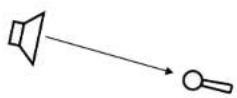
Fig. 105: One sound source, one receiver and no room. Only the direct sound is received.
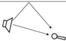
Fig. 106: One sound source, one receiver, and one reflecting surface. The sound is received twice. In the control room, this is normally experienced as comb filtering – see later.
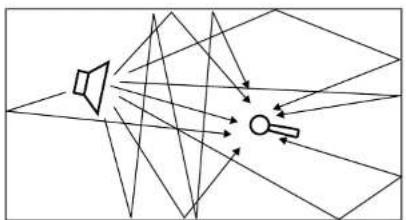
natural_image
Diagram showing light rays reflecting off a speaker into a lens (no text or symbols)Fig. 107: One sound source and one receiver in a typical room. The sound impulse is reflected on many surfaces. The reflections are perceived as reverberation.
Sabine's formula
Wallace Clement Sabine (1868-1919) is the father of modern acoustics. He found that reverberation time is described by a relationship between the room size and the amount of absorption in the room. Larger rooms will have longer reverberation. More absorption leads to shorter reverberation. This can be expressed in Sabine's formula:
T = 0.161 \* V / A
where:
▶ T: Reverberation time in seconds
V: Volume iñ m
A: Absorption in Sabine
▶ 0.161: A constant (to adapt the calculation to the actual units)
One square meter (1 m²) Sabine is comparable to an open window with an area of one square meter. The sound that hits this hypothetical window will disappear and never return. In other words: One square meter Sabine is one square meter with full absorption.
The basic formula sounds simple – but the problem is that the materials in the room will absorb differently at different frequencies. The absorption may range from nothing (fully reflective) to total absorption.
A proper reverb time should be constant with frequency, but this is not always the case because of the behavior of the materials in the room. The low frequencies are the hardest to control. This is why the reverberation time against frequency in practice may look like this:
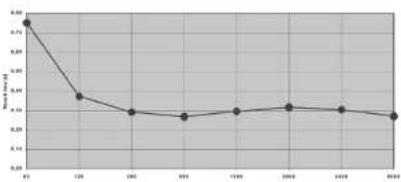
line
| Year | Value | |---|---| | 2011 | 9.85 | | 2012 | 8.35 | | 2013 | 7.65 | | 2014 | 7.55 | | 2015 | 7.55 | | 2016 | 7.65 | | 2017 | 7.65 | | 2018 | 7.65 | | 2019 | 7.65 | | 2020 | 7.65 |Fig. 108: Reverberation time measured in a control room. From 250 Hz and above, the curve is nicely placed around 0.3 seconds. But for lower frequencies, the reverb time rises to 0.75 seconds, which is too much.
Absorbers
All materials in a room act acoustically – even if they are not so-called "acoustical materials". Basically, there are three kinds of absorbers:
Membrane absorbers
This class of absorber includes wooden floors, windows, doors, etc. These absorbers provide absorption in the low end of the frequency range. Under normal conditions, large areas of a basic room belong to this class. While their efficiency is normally not very high, specially designed membrane absorbers can be very effective.
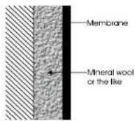
Fig. 109: Membrane absorbers
Resonance absorbers
Resonance absorbers include slit panels, perforated plates, Helmholtz resonators etc. These absorbers are normally used for midrange frequencies. The absorption is medium to high.

Fig. 110: Resonance absorbers
Porous absorbers
These absorbers include mineral wool, carpets, curtains, and so on. They can be very effective, but the thickness of the material has to be taken into account. Thin layers will only absorb the highest frequencies. Think of a rehearsal room in a concrete basement where the only damping is a carpet on the floor – this will do very little for low frequencies!
To absorb a given frequency (and all frequencies above), the thickness of the absorber must be the quarter of the wavelength of that frequency. Put differently: The front of the material must be placed at a distance of one quarter of the wavelength.
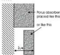
Fig. 111: Porous absorbers

tc electronic
Appendix 2: Acoustics
Diffusors
A diffusor provides diffuse reflection of the sound radiated against it. Diffusers can be very useful in situations where reflections are disturbing the sound image and it is not advisory to add further absorption. So in order to reduce flutter echoes, comb filtering etc., special elements can be placed on the "disturbing" surface. These elements must have dimensions comparable to the frequencies at which diffusion is wanted.
Absorption or diffusion?

natural_image
Two diagrams showing directional arrows with arrows pointing at different angles (no text or symbols)Fig. 112: Absorption versus diffusion
A special technique developed by Manfred Schroeder is very capable in making a smooth and controlled diffusion. These “Schroeder Diffusors” are available as prefab modules.

tc electronic
Appendix 2: Acoustics
Standing waves
Standing waves exist in all kind of rooms. Important parameters that will determine the frequencies around which the phenomenon exists as well as the distribution of these standing waves are the shape of the room, the dimensions of the room, and the relationship between the dimensions of the room.
How do standing waves occur?
Imagine a sound source. When a sound is emitted, the sound wave will propagate in all directions if no obstacles in sight. This will of course happen with the speed of sound.
Now, if the sound source is placed inside a room, the sound wave will hit the boundaries of the room. If the boundaries consist of acoustically hard (reflective) surfaces, the sound is reflected. If the angle of incidence is 90^ , the sound will be reflected right back where it came from. Under certain circumstances – for instance if the sound is reflected between two parallel walls –, the sound wave will meet itself again. This becomes a problem when the sound wave not only meets itself, but when it meets itself in phase. And this will happen when the distance between the walls is half a wavelength of the radiated sound wave. Or one whole wavelength – or 1.5, 2, 2.5 and so on.
This phenomenon is called standing waves. Actually, the sound wave is not “standing”. But it is experienced as that because the sound pressure maxima and minima are located in fixed places in the room.
flowchart
graph TD
    A[" "] --> B[" "]
    B --> C[" "]
    C --> D[" "]
    D --> E[" "]
    E --> F[" "]
    F --> G[" "]
    G --> H[" "]
    H --> I[" "]
    I --> J[" "]
    J --> K[" "]
    K --> L[" "]
    L --> M[" "]
    M --> N[" "]
    N --> O[" "]
    O --> P[" "]
    P --> Q[" "]
    Q --> R[" "]
    R --> S[" "]
    S --> T[" "]
    T --> U[" "]
    U --> V[" "]
    V --> W[" "]
    W --> X[" "]
    X --> Y[" "]
    Y --> Z[" "]
Fig. 113: The sound field is initially radiated exposing a radial wave front – but within a few reflections, the sound field has obtained a plane wave front.

tc electronic
Appendix 2: Acoustics
Room modes
These special frequencies are also called room modes. Standing waves between parallel walls are called axial modes. Other modes exist – for instance, tangential modes and radial modes (see the following illustrations). Normally, the axial modes are the strongest.
Fig. 114: Room modes: Axial modes
Fig. 115: Room modes: Tangential modes


Fig. 116: Room modes: Radial modes
Standing waves are characterized by having a maximum sound pressure at the boundaries of the room. Depending on the frequency there are one or more dips across the room.
In a box-shaped room, the frequencies can be calculated as follows:
$$ f = \frac {c}{2} \sqrt {\left(\frac {n _ {l}}{l}\right) + \left(\frac {n _ {b}}{w}\right) + \left(\frac {n _ {h}}{h}\right)} $$
where
▶ f = frequency in Hz
▶ c = speed of sound (approx. 340 m/s or 1130 ft/s)
▶ I = length of the room
▶ w = width of the room
▶ h = height of the room
▶ n = integer from 0 and up
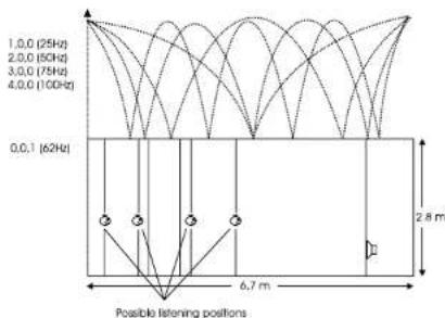
Fig. 117: Maxima of standing waves
The curves shown here express the area of the room where the respective frequency is audible. At the minima, that frequency's level is much lower (sometimes -40 dB compared to the maximum).
If the room's length, width and even height are identical, obtaining an even sound distribution can be very hard.
Prohibiting standing waves
Parallel walls in the room should be prevented. This will suppress the strongest modes.
When placing monitors, it is important that as few modes as possible are excited. This is why no monitor should be placed at the maximum of a standing wave.
When monitors are built into walls, you should therefore make sure that the opposite wall is not parallel to the wall with the monitor.
At low frequencies, a monitor can be considered as radiating its sound energy in all directions. This is also called a 4 radiation.
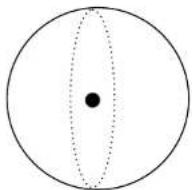
Fig. 118: 4 π radiation
When the monitor is placed close to a solid boundary (for instance a wall), the sound energy that should have been radiated in the direction of the wall is radiated into the free half space instead. Hence the sound pressure is doubled in the half space, which yields +6 dB. This is also called a 2π radiation.

Fig. 119: 2 π radiation
When the monitor is placed against two boundaries (for instance in a corner limited by two walls), it is now radiating its energy to the quarter space. Accordingly, the sound pressure is doubled twice, which yields +12 dB. This is also called a n radiation.

Fig. 120: π radiation
When the monitor is placed against three boundaries (for instance in a corner limited by the floor and two walls), the sound is radiated into 1/8 of the space. Compared to free space, the sound pressure now is increased by 18 dB. This is also called /2 radiation.
In practice, placing a monitor close to boundaries will influence the frequency range below 125 to 150 Hz.
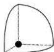
Fig. 121: π/2 radiation
Comb filtering
The filtering function that arises when a signal is added to itself after having been delayed in time is called a comb filter.
The resulting frequency response resembles a comb, hence the name.
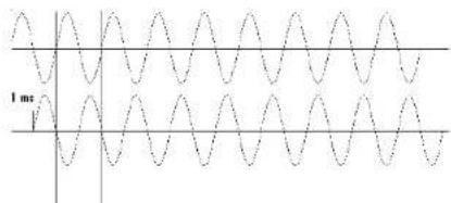
Fig. 122: Two 500 Hz sinusoidal tones added. The second tone is delayed 1 millisecond,
hence the sum is zero. Fig. 123: Two 1 kHz sinusoidal tones added.
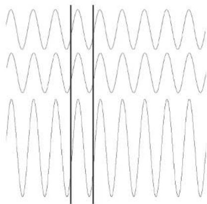
natural_image
Pure waveform diagram with no text, numbers, or symbolsThe summed level is doubled (+6 dB).
The comb filter function is almost never intentional – but it is heard all the time in audio productions, where it can arise both for acoustical and electrical reasons.
Acoustically, comb filter effects typically occur when part of the sound travels from source to recipient both on a direct path and via a single reflective surface. This reflection must be attenuated at least 10 dB and preferably 15 dB in order for it not to have an effect on the sound field at the recipient's position. Electrically, the phenomenon arises when two microphones with a certain distance between them capture the same signal and the level from each microphone is of the same order of magnitude.
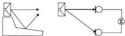
flowchart
graph TD
    A["Start"] --> B{Condition}
    B -->|Yes| C["Process Step 1"]
    B -->|No| D["Process Step 2"]
    C --> E["Output"]
    D --> F["Output"]
    G["Σ"] --> H["Sum"]
    H --> I["Feedback Loop"]
    I --> J["End"]
Fig. 124: Two typical situations in which comb filtering occurs, either acoustically or electrically
Generally speaking, all digital signal processing takes time. This means in practice that comb filter effects can arise if you send a signal through a signal processor and combine the processed (and hence delayed) signal with the original.

tc electronic
Appendix 2: Acoustics
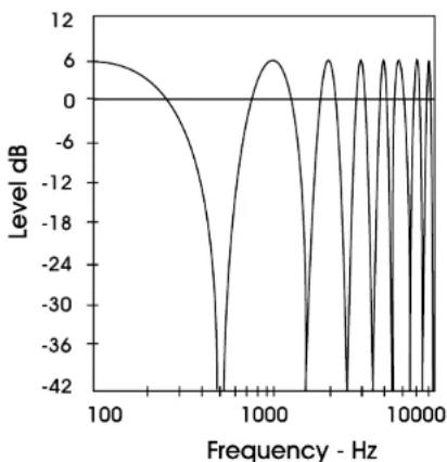
line
| Frequency - Hz | Level dB | | -------------- | -------- | | 100 | 6 | | 500 | -42 | | 1000 | 6 | | 5000 | -42 | | 10000 | 6 |Fig. 125: An example of a comb filter effect created by combining two signals with the same amplitude and a one millisecond delay between them. Dips occur due to cancellation at 500 Hz, 1.5 kHz, 2.5 kHz etc., and the two signals' levels double (+6 dB) at low frequencies with a full wavelength's delay at 1 kHz, 2 kHz, 3 kHz etc.
Dip frequencies
Cancellation occurs for a comb filter at all the frequencies where the two signals are in opposite phase. This occurs when the time delay comprises duration of 0.5, 1.5, 2.5 etc. periods. At 1 kHz, the period is 1 millisecond. Half of the period is 0.5 milliseconds.
If a time delay of precisely 0.5 millisecond occurs, this will result in cancellation not only at 1 kHz, but also at 2 kHz, 3 kHz, 4 kHz etc.
Rear wall cancellation
When the monitor is set up at some distance in front of a wall, reflections from the wall may occur and influence the perceived frequency response. This could result in comb filtering if all frequencies produced by the monitor were radiated in all directions. But monitors are typically only omnidirectional at low frequencies.
The result of the reflection is a single or a few dips in the frequency response perceived in front of the monitor.
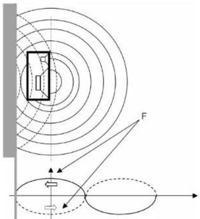
Fig. 126: A frequency (F) that has a wavelength of four times the distance to the rear wall is canceled because of the oppositely phased reflection.
The dip – or cancellation frequency – depends on the distance to the wall. If the distance is 1 meter, the first dip frequency will occur at a frequency with a wavelength of 4 meters.
$$ l = c / f $$
where
▶ I = wavelength (meters or feet)
▶ c = speed of sound (meters/second or feet/second)
▶ f = frequency [Hz]
Hence
$$ ↳ 4 = 3 4 4 / f $$
$$ ↳ f = 8 6 \mathrm{Hz} $$
A closer position will result in a cancellation at a higher frequency. This is then limited by the frequency where the monitor becomes directional and does not radiate sound to the rear.
A farther position will result in cancellation at a lower frequency. This is limited by the distance being so long, that the reflected sound is attenuated due to the long extra path travel.

tc electronic
Appendix 2: Acoustics
Subwoofers
A subwoofer is a monitor that reproduces low frequencies. The purpose is to take over from the main monitor(s) as frequencies approach the lower end of the frequency range – approximately below 120 Hz. For professional monitor systems, it is commonly preferred to use subwoofers below approximately 80 Hz – but of course, the best solution depends on the performance of the main monitors.
The low frequency contents of just one or all the main channels can be directed to one subwoofer.
Psychoacoustics tells us that there is no directional information in audio signals below approximately 120 Hz. Accordingly, a subwoofer should be placed in a position where the best distribution is achieved.
However, it is very important to reduce subwoofer distortion to an absolute minimum, because distortion will add harmonics (2, 3, 4 etc. times the frequency reproduced). Especially the third harmonic may dominate the signal. Reproducing a frequency of 100 Hz can result in the generation of an audible frequency component at 300 Hz, which presents directional information to the human hearing system.

tc electronic
Appendix 2: Acoustics
Bass management
Bass management is a very important and useful tool – and it is in general an absolute necessity if you want to work with a five channel setup in a small room. Bass management system s are designed to subtract the bass contents from all main channels and reproduce it using a subwoofer.
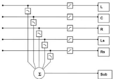
flowchart
graph TD
    A["Input"] --> B["Σ"]
    C["Input"] --> B
    D["Input"] --> B
    E["Input"] --> B
    F["Input"] --> B
    G["Input"] --> B
    H["Input"] --> B
    I["Input"] --> B
    J["Input"] --> B
    K["Input"] --> B
    L["Input"] --> B
    M["Input"] --> B
    N["Input"] --> B
    O["Input"] --> B
    P["Input"] --> B
    Q["Input"] --> B
    R["Input"] --> B
    S["Input"] --> B
    T["Input"] --> B
    U["Input"] --> B
    V["Input"] --> B
    W["Input"] --> B
    X["Input"] --> B
    Y["Input"] --> B
    Z["Input"] --> B
    AA["Input"] --> B
    AB["Input"] --> B
    AC["Input"] --> B
    AD["Input"] --> B
    AE["Input"] --> B
    AF["Input"] --> B
    AG["Input"] --> B
    AH["Input"] --> B
    AI["Input"] --> B
    AJ["Input"] --> B
    AK["Input"] --> B
    AL["Input"] --> B
    AM["Input"] --> B
    AN["Input"] --> B
    AO["Input"] --> B
    AP["Input"] --> B
    AQ["Input"] --> B
    AR["Input"] --> B
    AS["Input"] --> B
    AT["Input"] --> B
    AU["Input"] --> B
    AV["Input"] --> B
    AW["Input"] --> B
    AX["Input"] --> B
    AY["Input"] --> BA["Sub"]
    BB["L"] --> BC["Output"]
    BC --> BD["C"]
    BD --> BE["R"]
    BE --> BF["Ls"]
    BF --> BG["Rs"]
Fig. 127: Basic bass management setup
Checking summing phase cancellation
In a basic two channel setup or a five channel setup (such as ITU-775), a subwoofer is not specified and is not required. But when creating audio that should be played back using consumer equipment, one has to ensure that the mix will sound right in this situation. Many consumer setups today contain a subwoofer. Accordingly, it is very important to check what bass summing will sound like. If the program material basically is out of phase, the bass will be canceled when summed electrically. But this is not the case if the bass signals are reproduced by the main monitors and summed acoustically. The difference can be dramatic!
Controlling standing waves
It can already be difficult to position two monitors correctly in order to prevent the excitation of the standing waves. But placing five monitors is even more difficult.
In theory, each monitor should play under the same conditions – but this is rarely the case.
Three front monitors can normally be placed away from disturbing boundaries to prohibit the excitation of the standing waves. But in small rooms, the rear monitors are very often placed in corners or on a wall. Having the full frequency range reproduced from such monitors may lead to serious problems, resulting in poor low frequency distribution in the room. This is another reason for using bass management.
Simply put: When working with bass management, only one monitor – the subwoofer – has to be placed in a “safe” position. The crossover frequency can be set to a value just above the problematic frequency range.

tc electronic
Appendix 2: Acoustics
The LFE Channel
LFE is an abbreviation for “Low Frequency Enhancement” or “Low Frequency Effects”. While the first is the original name, the second is more correct with regards to its main applications.
LFE is also referred to as the ".1 channel", which indicates that the frequency range of this channel is only a fraction of the other channels in a multi channel setup. The actual frequency range is 20 Hz to 120 Hz.
When reproduced, the LFE signal is gained by 10 dB compared to the main channels. This provides a possibility of reproducing occasional high-level low frequency contents without affecting the general level setting of the main channels.
Signals being sent to the LFE channel should always be evaluated carefully, as not all transmission or reproduction systems may include this channel. In music production and mixing, there is usually no need for using this channel.
Delaying monitors
ITU 775
When using a 5.x setup with monitors arranged on a circle (as with ITU 775), the distance from the listener to each of the main monitors is the same.
If space is limited, the three front monitors can be arranged on a straight line instead of a circle. To compensate the center monitor being closer to the listener than the left and right monitor in this setup, the center signal can be delayed. To obtain coincident arrival of the sound from all front monitors, a delay between 0 and 3 milliseconds is used for compensation.
The speed of sound is approximately 340 m/s or 1130 ft./s. Accordingly, approximately 1 millisecond delay will be used to virtually move the monitor 1 foot or 30 centimeters backwards.
Cinema setup
In a cinema setup, the front monitors are always arranged on a straight line. Here, the audience is closer to the surround monitor(s) than to the front monitors. In order to retain the directional information towards the screen, the surround monitors are delayed.
Normally the psychoacoustic Haas effect is taken into account. In the listening position, the sound from the surround monitors will arrive about 15 to 20 milliseconds after the sound from the front monitors. The delay times involved with cinema processing for the surround channel is dependent on the size of the mixing facility, the cinema, or the home theatre/living room. Proper setup requires calculating the difference in distance between the front monitors and the closest surround monitor. Then, the time difference is calculated. To this, 15 to 20 milliseconds are added.
Example: From a listening position, the distance to the front monitors is 20 meters and five meters to the surround monitors, so the difference is (20 - 5 =) 15 meters. The time difference that needs to be compensated is 15/340 sec, which equals 0,044 seconds or 44 milliseconds. To this value, 15 milliseconds are added. Accordingly, the surround signal has to be delayed 59 milliseconds (or the closest possible value).

tc electronic
Appendix 2: Acoustics
Line-up and calibration
Acoustic summation of audio signals
When summing two sound sources (for example, two monitors), the resulting total sound level depends on both the signal and the acoustics. The sound sources can be correlated or uncorrelated. The listening position (or measurement position) can be either in the direct sound field or in the diffuse sound field.
In the direct sound field, there is only one sound direction. This direct field exists either in the open, in a reflection-free room or close to the monitors.
The diffuse sound field occurs in a room when you are so far away from the monitors that the portion of direct sound is less than the sum of all the reflections.
The distance from the monitors where the direct sound field and the diffuse sound field are equally large is called the critical distance. In a control room, it can typically be 1 to 3 meters. The near field in front of the monitors can be regarded as a direct field.
If all monitors are in phase, the sum of the sound pressure from two monitors playing at the same level is 3 dB – unless the signals are correlated (identical) and the sum is measured in the direct field. In this case, the resulting sound pressure level is 6 dB higher than the level of the individual monitors.
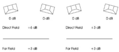
Fig. 128: Correlated (left) and uncorrelated (right) signals
Acoustic calibration of multi-channel systems
When working with sound for film, calibration of the acoustic sound levels has been a requirement for many years, but it has not been particularly common in other branches of the sound industry. However, with the widespread use of multi-channel formats for all forms of music and film presentation in the home, the benefits of controlling levels have become obvious in recent years.
It is important to differentiate between production for the cinema and production for 5.1 channel reproduction in the home based upon ITU 775.

tc electronic
Appendix 2: Acoustics
Calibration of 5.1 in an ITU-775 arrangement
In a 5.1 system based on the ITU arrangement, all main channels are operated under the same conditions: There is one monitor per channel, and each monitor is placed at the same distance from the listener. However, there is no international agreement on the level or the bandwidth of the noise signals that should be used for acoustic calibration. Pink noise is a good starting point, as it includes all frequencies. However, it is impractical due to its “unsettled” character, which makes it difficult to measure at low frequencies.
Surround Sound Forum
Surround Sound Forum is a German interest group composed of the VDT (Verband Deutscher Tonmeister; Association of German Sound Engineers), the Institut für Rundfunktechnik (IRT) and the Schule für Rundfunktechnik (SRT). The SSF has prepared calibration guidelines, which are generally accepted in Europe. They specify three test signal, which are recorded at -18 dBFS (RMS).
| Signal (only in one channel) |
| SLOW |
| Sound pressure level |
| SLOW |
| RMS level |
| PPM level |
| t < 10 ms |
| PPM level |
| t < 0.1 ms |
[dB] [dB] [dB] [dB] [dB(A)]
| 1 kHz sine -18 -18 -18 | |||||
| Pink noise | -9 | -13 | -18 | 82 | 78 |
| 20 Hz to 20 kHz | |||||
| Pink noise | -11 | -15 | -20 | 80 | 78 |
| 200 Hz to 20 kHz | |||||
SMPTE
The corresponding SMPTE standard (RP155) uses a standard of -20 dBFS for the reference Association level. Be GetheC-Sighted sound pressure level of a 500 to 2 kHz noise signal ends up at 83 dB.

tc electronic
Appendix 2: Acoustics
Calibration of cinema systems
In a cinema, the listeners are sitting far from the monitors. Presumably, the majority sits in the diffuse sound field. Attempts are made to establish a diffuse sound field from the surround monitors. Accordingly, when the sound pressure is measured inside the cinema or in a mixing theatre, it must be averaged over many different measurement locations. The typical basis for the majority of the standards is measuring at four or more locations. If there are different areas for the audience (for example main floor and balcony), measurements should be made in at least four locations in each area. Before these measurements can be made, the system's frequency response must also be in order.
Technical specifications
Clarity X software version 1.3.00 – Build 3275 – Reference manual (updated 2016-10-18)
| MADI License Option | |
| Frame Configuration Clarity X with Clarity X Remote Control and 3600A Reference Microphone | |
| Front Indicators/Control Status LED: Running, Net, Remote and Sync. IP address reset button. | |
| Finish Black anodized aluminum face plate. Plated steel chassis | |
| Dimensions 19 x 1.75 x 13.2 inches (483 x 44 x 334 mm), 1 RU | |
| Weight 9.0 lbs. (4.7 kg) | |
| Mains Voltage 100 to 240 VAC, 50 to 60 Hz auto-select | |
| Fan High quality fan | |
| Power Consumption 20 W typ | |
| Warranty, Parts and Labor 2 years | |
| EMC | |
| Complies with EN 55103-1 and EN 55103-2, FCC part 15 class B, CISPR 22 class B | |
| Safety | |
| Certified to IEC 60065, EN 60065, UL 6500 and CSA E65 | |
| Environment | |
| Operating Temperature | 32°F to 122°F (0°C to 50°C) |
| Storage Temperature | -22°F to 167°F (-30°C to 70°C) |
| Humidity | Max. 90% non-condensing |
| Control interface | |
| Ethernet and TC Icon Remote Control | 2 ports, RJ45, 10/100 Mbits/s, Base-T, SNMP-enabled |
| Clarity X Remote Control | RJ45 connector |
| Clarity X Remote Control | |
| Controls | 12 buttons with LEDs, 1 "Valid" LED, 1 high-end potentiometer |
| Finish Black anodized aluminum face plate. Glass blasted anodized chassis | |
| Dimensions 4.8 x 3.0 x 1.9 inches (122 x 77 x 48 mm) | |
| Weight 0.7 lbs. (0.3 kg) | |
| Max cable length | 100 m using a standard microphone cable |
| General Processing | |
| Number of Meters | 2 x LM8 Loudness Radar Meters, 2 x True-peak Meters, SPL Meter, Dose Meter, Stereo Deviation Meter, Center Ratio Meter |
| Input Audio Format | 2.0, 5.1, 7.1 |
| Output Speakerset Configuration 44.1 to 48 kHz: | 7 channel surround + 0 or 1 subwoofer, 7 channel surround + 0 or 1 subwoofer, Stereo + 0 to 2 subwoofers |
| Output Speakerset Configuration 44.1 to 96 kHz: | 5 channel surround + 0 to 2 subwoofers, Stereo + 0 subwoofers, Stereo + 0 subwoofers |
| Number of Audio Channels Processed | 8 in, 8 out |
| Audio Processing Delay 100 samples, 2.08 ms @ | 48 kHz (digital in to digital out) |
| Adjustable On-line Delay | 0 to 1000 msec. Unit: ms, frames 24, 25, 30, 50, 50. Resolution: 1 ms or 0.1 frames |

tc electronic
Technical specifications
| Adjustable Per-Speaker Delay 0 to 100 msec. Resolution: 10 usec | |
| Speaker Calibration Standard EBU R128, SMPTE | RP200, ATSC A85 |
| Total Speaker Calibration Precision ±0.5 dB | |
| Inter-speaker-channel Calibration Precision ±0.05 dB | |
| SPL measurement 48 dB(A) to 130 dB(A) | |
| Frequency Response DIO DC to 23.9 kHz ±0.01 dB | |
| Audio Processing Resolution 40 bit precision, bit transparent | |
| Internal Sample Rates 44.1, 48 kHz, 96 kHz | |
| Internal Clock Precision ±30 PPM | |
| External Sample Rates Same as internal ±1.5 % | |
| Interface Function | Synchronous, bit transparent |
| Digital IO Engine | TC developed DICE^TM core |
| Jitter Rejection Engine | Upgraded JET^TM technology. Based on System 6000 |
| Jitter Tolerance (input) | > AES3-2009 (master and slave input) |
| Jitter Rejection Low-Pass Filter | < -3 dB @ 10 Hz, < -100 dB @ 600 Hz, 4th order |
| Jitter Gain (in-to-out) | < 1 dB |
| Output Jitter (@ clean source) < 1 ns peak, BW: 700 Hz to 100 kHz | |
| AES Input / Output | |
| Connectors | D-SUB-25 incl. cable for XLR, 110 Ohm, Yamaha pinout, M2.6mm thread |
| Number of Channels | 16 in, 16 out |
| Formats Supported | AES/EBU (24 bit), AES3 |
| Status Bits | In: Accepts all, Out: Pro-status bits |
| Complies with Standards | AES3-2009 |
| Digital Output Phase | < 0.5 % of sample period |
| Input Variation Before Sample Slip | ±49.9 % of sample period |
| Input Signal Tolerance | 0.2 to 7 Vpp |
| Output Signal Level | 3.3 Vpp ±20 %, terminated |
| TOS Input | |
| Format | AES/EBU (24 bit), S/PDIF (24 bit), EIAJ CP-340, IEC 60958 |
| Type | Optical Tos-link |
| Number of Channels | 2 |
| Input Variation Before Sample Slip | ±49.9 % of sample period |
| Analog Output | |
| Connectors | D-SUB-25, Yamaha/Tascam pinout, M2.6mm thread |
| Number of Channels | 8 out |
| Format | Ground sensing design |
| Output Impedance | 20 Ohm |
| Full Scale Output Level @ 0 dBFS | +12 dBu max, with analog -18 dB DIM |
| Dynamic Range > 121 dB (incl. -18 dB DIM), unweighted, BW 20 to 20kHz | |
| THD+N < -99 dB @ 1 kHz, -3 dBFS (@ +12dBu), < -96 dB @ 1 kHz, -3 dBFS (@ -18 dB DIM) | |
| Freq Response 20 Hz to 20 kHz, +0/-0.2 dB | |
| Crosstalk < -102 dB, 20 Hz to 20 kHz | |
| D to A Conversion 24 bit, 128 x Oversampling Bitstream | |
| D to A Delay 21 samples, 0.44 ms @ 48 kHz | |
| Headphones Output | |
| Connectors 1/4" Phone Jack (stereo) | |
| Format High drive, Impedance Compensating, Short circuit protected | |
| Output Impedance 3.4 Ohm | |
| Headphones Impedance 8 to 600 Ohm | |
| Full Scale Output Level @ 0 dBFS | +21.5, +17.5, +12.5, +6.5 dBu (different headphones impedance settings) |
| THD+N | < -93 dB @ 1 kHz, -3 dBFS, 275 Ohm load (“>275 Ohm” headphones impedance setting) |
| < -86 dB @ 1 kHz, -3 dBFS, 50 Ohm load (“50 to 300 Ohm” headphones impedance setting) | |
| < -86 dB @ 1 kHz, -3 dBFS, 25 Ohm load (“25 to 100 Ohm” headphones impedance setting) | |
| < -75 dB @ 1 kHz, -3 dBFS, 8 Ohm load (“8 to 50 Ohm” headphones impedance setting) | |
| Dynamic Range | > 109 dB, unweighted, BW 20 Hz to 20 kHz (all headphones impedance settings) |
| Freq. Response +0/-0.2 dB, 20 Hz to 20 kHz | |
| Crosstalk < -102 dB, 20 Hz to 20 kHz | |
| Power | 112 mW @ 600 Ohm load (“>275 Ohm” headphones impedance setting) |
| 263 mW @ 32 Ohm load (“25 to 100 Ohm” headphones impedance setting) | |
| D to A Conversion 24 bit, 128 x Oversampling Bitstream | |
| D to A Delay 21 samples, 0.44 ms @ 48 kHz | |
| Aux Input | |
| Connectors 1/8" Phone Jack (unbalanced, stereo) | |
| Input Impedance | 500 Ohm |
| Full Scale Input Level @ 0 dBFS | +5 dBu |
| THD+N < -98 dB @ 1 kHz, -3 dBFS | |
| Dynamic Range > 105 dB, unweighted, BW 20 to 20 kHz | |
| Freq. Response +0/-0.1 dB, 20 Hz to 20 kHz | |
| Crosstalk < -75 dB, 20 Hz to 20 kHz | |
| A to D Conversion 24 bit, 128 x Oversampling Bitstream | |
| A to D Delay 29 samples, 0.60 ms @ 48 kHz | |
| Calibrated Microphone and Microphone Input | |
| Model Number | TC Electronic, 3600A Reference Microphone. Microphone holder included (5/8" and 3/8") |
| Characteristic | Omni, Random Incident optimized in DSP |
| System Complies with Standard | IEC 61672 (where applicable) |
| Maximum microphone cable length | 100 m |
Technical specifications
MADI License Option
Connectors 1 BNC In, 1 BNC Through. 75 Ohm
Function Audio input and MADI through
Number of channels 28, 32, 56, 64 in
Samples Rates
44.1, 48 kHz, 96 kHz, no Varispeed supported, 96 kHz legacy mode not supported
Complies with Standards AES10-2008 r2014
Digital Output Phase < 0.5 % of sample period
Input Variation Before Sample Slip ± 25 % of sample period
Input Signal Tolerance Complies to AES10-2008 r2014
Output Signal Level Complies to AES10-2008 r2014
Fig. 110: 2 radiation 179
Fig. 109: 4 radiation 179
Fig. 103: Absorption versus diffusion 176
Fig. 117: A frequency (F) that has a wavelength of four times the distance to the rear wall is canceled because of the oppositely phased reflection. 182
Fig. 116: An example of a comb filter effect created by combining two signals with the same amplitude and a one millisecond delay between them. Dips occur due to cancellation at 500Hz , 1.5kHz , 2.5kHz etc., and the two signals' levels double (+6 dB) at low frequencies with a full wavelength's delay at 1kHz , 2kHz , 3kHz etc. 181
Fig. 20: Assigning Clarity X in TC Icon 42
Fig. 24: Assigning Clarity X in TC Icon 50
Fig. 34: Audio formats and Bass Management modes – overview 68
Fig. 35: Audio formats and Bass Management modes – overview ctd. 69
Fig. 80: Auto Logging – Log Select page, with meter M2 enabled for logging 143
Fig. 81: Auto Logging - Log Setup page 144
Fig. 12: Balanced to unbalanced – proper wiring 33
Fig. 118: Basic bass management setup 184
Fig. 33: Bass Management page, Bass
Management set to Extract 67
Fig. 39: Calibrating the right speaker in a 5.1
setup to EBU R128 79
Fig. 11: Clarity X back panel connectors (shown with optional MADI ports) 32
Fig. 62: Clarity X Dose Meter and Dose Reset
button as seen in the right pane of the TC Icon
Main View 117
Fig. 61: Clarity X Dose Meter showing "Not Cal" for a Speaker Setup not declared as Ready.... 116
Fig. 9: Clarity X front panel 29
Fig. 10: Clarity X front panel indicators 29
Fig. 8: Clarity X hardware options: With MADI (top) and without MADI (bottom) 27
Fig. 79: Clarity X log file header 141
Fig. 52: Clarity X Main View – input and output panes showing Page 1 104
Fig. 53: Clarity X Main View – input and output panes showing Page 2 104
Fig. 54: Clarity X Main View, left pane, page 1 showing the Radar Meter and Source overview, Stereo Deviation Meter and Center Ratio Meter. 105
Fig. 55: Clarity X Main View, left pane, page 2 showing Radar statistics, True Peak Meter and Source overview, Stereo Deviation Meter and Center Ratio Meter 107
Fig. 56: Clarity X Main View, right pane, page 1 showing the current speaker set, the Dose Meter, the Speaker Set overview, and various status indicators 108
Fig. 57: Clarity X Main View, right pane, page 2 showing the Dose Meter, the Reset Dose button, the Speaker Set selection buttons and various status indicators....110
Fig. 68: Clarity X Remote Control 121
Fig. 7: Clarity X signal flow diagram. For more information on a section, please click or tap the respective part of the diagram. 25
Fig. 1: Clarity X software on the TC Electronic software download page 17
Fig. 2: Clarity X software on the TC Electronic software download page 19
Image list
Fig. 85: Clarity X software on the TC Electronic software download page 154
Fig. 86: Clarity X software on the TC Electronic software download page 156
Fig. 87: Clarity X software (.tca) in the OS X Finder 156
Fig. 26: Clarity X Status page 54
Fig. 18: Confirmation of Clarity X reboot 41
Fig. 17: Confirmation of new Clarity X IP address 41
Fig. 19: Connecting Clarity X to a computer via Ethernet 42
Fig. 119: Correlated (left) and uncorrelated (right) signals 187
Fig. 93: Device UI locked 164
Fig. 70: Dynamic Range Tolerance (DRT) for consumers in different listening situations 126
Fig. 58: Edit / Format page 112
Fig. 69: Edit / Remote page 123
Fig. 82: Edit - Setup - M1 page 146
Fig. 5: Ejecting the TC Icon disk image 20
Fig. 16: Entering a new Clarity X IP address 40
Fig. 36: EQ page with Band 3 deactivated and Band 5 selected for editing....73
Fig. 22: Fader label (two triangles) indicating Fine adjustment mode for the currently selected parameter (Delay) 47
Fig. 37: Frame / Phones page 75
Fig. 27: Frame / Routing page 58
Fig. 40: Frame / Set 1 / Cal page 81
Fig. 21: Icon symbol 46
Fig. 46: Info display for M2 preset 92
Fig. 30: I/O setup - Clock page 60
Fig. 31: I/O Setup - MADI page 64
Fig. 38: Level differences when mixing at different sound pressure levels 78
Fig. 49: Library Bank page 96
Fig. 48: Library Project Delete page 95
Fig. 44: Library Studio Recall page 92
Fig. 47: Library Studio Store page 93
Fig. 75: LM8 Main page 133
Fig. 73: LM8 Radar 128
Fig. 74: LM8 Radar page 130
Fig. 76: LM8 Setup page 137
Fig. 77: LM8 Statistics page 139
Fig. 78: Log page with two log files 140
Fig. 45: M2 Preset Recall button with Info tag 92
Fig. 50: Main Edit page 98
Fig. 108: Maxima of standing waves 178
Fig. 100: Membrane absorbers 175
Fig. 4: Moving TC Icon to the OS X applications folder 19
Fig. 15: Network identification page in TC Icon software 40
Fig. 59: Noise Floor Zoom 114
Fig. 60: Noise-induced hearing loss risks 116
Fig. 98: One sound source and one receiver in a typical room. The sound impulse is reflected on many surfaces. The reflections are perceived as reverberation. 173
Fig. 96: One sound source, one receiver and no room. Only the direct sound is received. 173
Fig. 97: One sound source, one receiver, and one reflecting surface. The sound is received twice. In the control room, this is normally experienced as comb filtering – see later. 173
Fig. 14: OS X Network preferences 39
Fig. 6: OS X security warning about application from an unidentified developer 20
Fig. 42: Overview of the Clarity X data structure 88
Fig. 43: Overview of the Clarity X data structure in TC Icon 88
Fig. 71: Peak level normalization 126
Fig. 102: Porous absorbers 175
Fig. 83: Preferences page 149
Fig. 88: Reset to Defaults button on the Frame / System / Setup / Version page 159
Fig. 89: Reset to Defaults confirmation dialog ..... 159
Fig. 101: Resonance absorbers 175
Fig. 99: Reverberation time measured in a control room. From 250Hz and above, the curve is nicely placed around 0.3 seconds. But for lower frequencies, the reverb time rises to
0.75 seconds, which is too much. 174
Fig. 105: Room modes: Axial modes 178
Fig. 107: Room modes: Radial modes 178
Fig. 106: Room modes: Tangential modes 178
Fig. 28: Routing an input channel to a Source Module channel 58
Fig. 29: Routing a Speaker Set channel to a physical output channel 58
Fig. 95: Setup – Color page 167
Fig. 91: Setup – Devices page 163
Fig. 90: Setup – Info page 162
Fig. 25: Setup – No devices detected 52
Fig. 92: Setup – Security page 164
Fig. 94: Setup - UI page 166
Fig. 41: Signals for the left and right speakers delayed by 2.4 ms to compensate for the center speaker being 80 cm closer to the listener.....84
Fig. 32: Speaker Set Configuration page for Speaker Setup 1 65
Fig. 84: Studio Setup active – Speaker Sets enabled 151
Fig. 72: Target loudness based on a consumer's Dynamic Range Tolerance 127
Fig. 3: TC Icon software app icon 19
Fig. 23: TC Icon software – On-screen keyboard 48
Fig. 104: The sound field is initially radiated exposing a radial wave front – but within a few reflections, the sound field has obtained a plane wave front. 177
Fig. 51: Tone page 101
Fig. 114: Two 1 kHz sinusoidal tones added. The summed level is doubled (+6 dB). 180
Fig. 113: Two 500 Hz sinusoidal tones added. The second tone is delayed 1 millisecond, hence the sum is zero. 180
Fig. 115: Two typical situations in which comb filtering occurs, either acoustically or electrically 180
Fig. 13: Windows Internet control panel 39
Fig. 112: π/2 radiation 179
Fig. 111: π radiation 179
tc electronic
tc electronic

tc electronic
Clarity X software version 1.3.00 - Build 3275 - Reference manual (updated 2016-10-18)
- tc electronic
- Safety information
- Important safety instructions
- Warning
- Service
- EMC/EMI
- For customers in Canada
- Getting support
- Before you get started
- Register your product
- Stay up-to-date on loudness
- Unpacking and setup
- Package contents
- Setup
- Licenses
- Obtaining a license
- Software: TC Icon and Clarity X firmware
- TC Icon software:
- TC Clarity X firmware:
- Finding and installing TC Icon software – Microsoft Windows
- Clarity X
- Updating TC Icon software (Windows)
- Finding and installing TC Icon software - OS X
- Running TC Icon software for the first time (OS X)
- Updating TC Icon software (OS X)
- Clarity X: An introduction
- Clarity X core features
- Calibrated Listening
- Visual feedback
- Speech intelligibility
- Hearing loss protection
- Clarity X Clock and Jitter Rejection
- Clarity X signal flow diagram
- Clarity X – Basic concepts and operation
- Operating Clarity X
- Hardware versions
- Clarity X presets
- Clarity X status indicators and ports
- Front panel indicators
- Running LED
- Net LED
- Remote LED
- Sync LED
- Front panel reset button
- Resetting the IP address of a Clarity X unit
- Resetting Ethernet communication
- Back panel connectors
- MIC IN Microphone input (calibrated)
- PHONES – Headphone connector
- ANALOG LINE/ MONITOR OUT (D-SUB - 8 channels)
- OPTICAL IN - TOS-link
- ETHERNET 1 & 2
- Remote in
- Power inlet
- Setting up Clarity X
- tc electronic Setting up Clarity X
- Networking basics and troubleshooting
- Finding and changing the TCP/IP address and subnet mask on a computer running Windows
- Finding and changing the TCP/IP address and the subnet mask on a computer running OS X
- Changing the Clarity X IP address
- Changing the Clarity X subnet mask
- Resetting the IP address of a Clarity X
- Quick Setup
- Keeping your Clarity X up-to-date
- Basic operation using TC Icon software
- TC Icon software – introduction
- Basic TC Icon operation
- TC Icon interface: Tabs versus pages
- TC Icon modes: Base and Device operation
- Switching between Base and Device operation modes
- TC Icon faders
- Using Faders for fine adjustments
- TC Icon on-screen keyboard
- Accessing Clarity X
- tc electronic Accessing Clarity X
- Operating multiple computers and/or TC HD devices in one network
- Scanning and rescanning a network for devices
- Obtaining Clarity X status information
- Clarity X status page
- Source indicator
- Lock indicator
- Nominal Rate indicator
- Running indicator
- Network indicator
- Remote indicator
- Sync indicator
- Frame Identification parameter
- Temperature indicator
- Setting up audio and syncing
- Setting up audio and syncing – introduction
- Signal routing
- Editing input routings
- Editing output routings
- Clock Setup
- Clock Status section
- Lock status indicator
- Sample Rate indicator
- Input State indicators (AES, TOS, MADI)
- Master Clock and AES Setup section
- Clock Master parameter
- Internal Rate parameter
- Sample rate range buttons (44.1-48 and 44.1-96)
- Sync Source parameter
- External Clock Accept rate parameter
- Clock Freewheeling parameter
- MADI setup
- MADI Preselect Channels section
- MADI Router Ch. parameter
- MADI In Channel parameter
- MADI - Available Channels display
- MADI - Available Channels LED
- Speaker Set configuration
- Configuration page
- Configuring a speaker set
- Ready button
- Bass Management page
- Mode parameter
- Off setting
- Extract setting
- When to use Extract Mode
- Distribute setting
- When to use Distribute Mode
- Audio formats and bass management modes – overview
- tc electronic Setting up audio and syncing
- Lo Cut (Main) parameter
- Lo Order (Main) parameter
- Hi Cut (Sub) parameter
- Hi Order (Sub) parameter
- Hi Cut parameter
- EQ page
- Channel Selection
- Channel Select parameter
- Using the Equalizer
- Activating or deactivating a frequency band
- Editing the settings of a frequency band
- Copying EQ band settings from one channel to another
- Bypassing the equalizer
- Frequency band parameters
- Filter type parameter
- Filter frequency parameter
- Filter frequency gain parameter
- Phones setup
- An introduction to headphone calibration
- Vendor parameter
- Model parameter
- Impedance display/parameter (top)
- Gain Trim parameter
- Balance parameter (top)
- Impedance parameter
- Gain parameter
- Balance parameter (bottom)
- Speaker Set calibration
- Speaker Set calibration – introduction
- Calibration
- Calibrating a Speaker Set – Basic Steps
- Using the Wizard for Speaker Set calibration
- Speaker Set calibration using the Wizard – step by step
- Calibration Process and Scope
- Compensation delay for subwoofers
- Multi Point Sub Calibration
- Reading the Phase Check Results page and fixing Phase Inversion issues
- Speaker Size Selection
- Calibration Results Page
- Post-calibration optimization
- Manual Calibration
- Manual Speaker Set Calibration – Step by Step
- Cal Generator section
- Calibration Method parameter
- Calibration button
- Acoustical Level parameter
- Microphone SPL display and Reset button
- Cal Channel section
- Speaker Size parameter
- Sweet Spot parameter
- Phase Adjustment parameter
- [Speaker] Delay parameter
- [Speaker] Level parameter
- Speaker Level and Delay
- compensation indicators
- Speaker positions and Speaker Delay
- Speaker Delay Example
- A shortcut to calculating and setting speaker distances
- Alternative sweet spots
- Clarity X sweet spots
- Sweet spot parameters
- Selecting sweet spots
- The Library: Recalling, storing and deleting settings
- Studio, Project, Routing, Engine and M2 presets
- Studio
- Project
- Route
- Engine
- The Library concept
- Factory presets - 44.1-48 versus 44.1-96
- Factory presets and Fader assignment
- Recall page
- Preset information
- Store page
- Storing Presets
- Naming Presets
- Adding Preset Information
- Operating the unit while renaming presets
- Delete page
- Operating the unit while deleting presets
- Bank page
- Copying Presets
- To copy from a Bank to a file on disk
- To copy from a file on disk to a Bank
- Signal Source and Speaker Set configuration
- Main Edit page
- Src 1 to Src 3 selection buttons
- Src 1 to Src 3 Format parameters
- Src 1 to Src 3 Gain parameters
- Tone „LED“
- Select Solo button
- Mute buttons
- Solo buttons
- Monitor Out section
- Delay parameter
- Ref / Ref 2 / Ref 3 Select buttons
- Cut button
- Dim button
- Speaker Set parameter
- Ref Level 2 and Ref Level 3 parameter
- Master Fader parameter
- Tone page
- SPL Weighting parameter
- Noise Type parameter
- Level RMS parameter
- Noise Correlate parameter
- Freq parameter
- Sine Level parameter
- All button
- On button
- Microphone SPL and Signal Meter section
- Clarity X Main view – Meters and Operation
- Clarity X main view - introduction
- Main view – left pane – page 1
- Radar Meter
- Source Overview
- Center Ratio Meter
- Main view – left pane – page 2
- Reset M1 button
- Main view – right pane – page 1
- Speaker Set display
- Dose Meter
- Speaker Set Overview
- Status indicators
- Mute/Solo status indicator
- Downmix status indicator
- M/S status indicator
- REF level status indicator
- Delay status indicator
- "Other" status indicator
- Main view – right pane – page 2
- Downmix and other processing functions
- Edit Format Page
- Downmix Enable button
- Downmix parameter
- Auto setting
- Gain parameters (L/R, C, Back, Side)
- Mono/Side section
- Mono button
- Side button
- Noise Floor section
- About Noise Floor Zoom
- Noise Floor Zoom Enable button
- NF Zoom Level parameter
- Dose Metering
- Hearing Loss
- Sound Exposure
- Sound Exposure Level
- Sound Exposure Level versus Sound Pressure Level
- Customizing Dose Metering with the Criterion parameter
- Clarity X Remote Control
- Using the Remote Control
- Remote Control Features
- Clarity X Remote Control reference
- REF - Reference Level key
- ALT Key
- DIM/CUT key
- F1 to F3 - Function keys
- Master Volume Dial and VALID LED
- Mute/Unmute/Solo buttons for each channel
- Solo Function
- Working with 7.1 setups
- Configuring the Remote Control
- F1 Key to F3 Key parameters
- ALT key parameter
- M2 - The LM8 Meter
- LM8 - introduction
- LM8 core features
- TC's Universal Database of Loudness
- LM8 - Basic use and setup
- Pausing and resetting the Radar display
- Working with LM8 presets
- LM8 Radar Page
- Outer Ring: Current Loudness
- Long-term measurements
- Reset button
- Universal Descriptors and Dolby LM100
- Universal Descriptors and AC3 Metadata
- True-peak meters
- LM8 Main page
- Descriptors section
- Descriptor 1 / Descriptor 2 parameters
- Loudness Max setting
- Sliding Loudness parameter
- Loudness Max parameter
- Loudness section
- Loudness Std. parameter
- BS.1770-3 setting
- Leq(K) setting
- Center of Gravity setting
- LU Reference parameter
- Audio Format parameter
- LM8 Setup page
- Momentary Range parameter
- Radar Speed parameter
- Radar Resolution parameter
- Low Level Below parameter
- Peak Indicator parameter
- Gain Weighting section
- Back L/R parameter
- Side L/R parameter
- True Peak Meters section
- (True Peak Meters) On parameter
- LM8 Statistics page
- About PLR (Peak to Loudness Ratio)
- LM8 log files
- Log file resets
- Log page
- Common Log File Folder
- Dump log button
- Show Log Header button
- Delete Log button
- Device ID field
- Additional information when Auto Logging is enabled
- Next log retrieval
- Last log
- Log file format and structure
- Log file header
- Log file name
- Log file example
- Working with log files
- Auto Logging
- Log Select page
- Button "LED" states
- Log Setup page
- Auto log button
- Log File Folder
- Interval field
- Day / Hour / Minute fields
- Next Auto Log Retrieval display
- Countdown display
- Retrieving Log From display
- M1 Meter configuration
- M1 - introduction
- Loudness Std parameter
- M1 Meter Type parameter
- Upper Bargraph parameter
- Lower Bargraph parameter
- Left Descriptor / Right
- Descriptor parameters
- M1 Settings section
- Outer Ring parameter
- Outer Ring Range parameter
- Preferences
- Preferences page
- Dimension Unit parameter
- Loudness Unit parameter
- Frame Rate parameter
- Delay Unit parameter
- Time Period parameter
- Master Fader section
- Criterion Level parameter
- Calibration Microphone section
- Studio Setup section
- Studio Setup Enable button
- Clarity X firmware update and Device Reset
- Finding and installing Clarity X firmware – Microsoft Windows
- Firmware
- TC Icon Software
- Finding and installing Clarity X firmware - OS X
- Locating and transferring the Clarity X firmware file – example 1
- Resetting your Clarity X
- TC Icon Setup
- Accessing the Icon Setup pages
- Info page
- Devices page
- Detect button
- Assigning devices to the available slots
- Security page
- Sticky Clip button
- Lock Device UI button
- Joystick page
- UI (user interface) page
- TC Icon Window parameter
- Faders at bottom setting
- Fader at right side setting
- No faders setting
- Color page
- Color Scheme parameter
- Color Element parameters
- Appendix 1: Links and additional information
- Support resources
- TC Electronic on...
- TC HD resources
- Product-related information
- Appendix 2: Acoustics
- Introduction
- Good acoustics
- Reverberation time
- Why do we have reverberation?
- Sabine's formula
- T = 0.161 \* V / A
- Absorbers
- Membrane absorbers
- Resonance absorbers
- Porous absorbers
- Diffusors
- Standing waves
- Room modes
- Prohibiting standing waves
- Comb filtering
- Dip frequencies
- Rear wall cancellation
- Subwoofers
- Bass management
- Checking summing phase cancellation
- Controlling standing waves
- The LFE Channel
- Delaying monitors
- Line-up and calibration
- Calibration of 5.1 in an ITU-775 arrangement
- Surround Sound Forum
- SMPTE
- Calibration of cinema systems
- Technical specifications
- Image list
Brand : TC ELECTRONIC
Model : Clarity X
Category : Audio Effects