
DHG-M55CV - Digital Receiver SONY - Free user manual and instructions
Find the device manual for free DHG-M55CV SONY in PDF.


| Product Type | DVD/HDD Recorder |
| Brand | Sony |
| Model | DHG-M55CV |
| Dimensions (W x H x D) | 430 x 68 x 300 mm |
| Weight | 4.5 kg |
| Power Supply | 220-240 V AC, 50/60 Hz |
| Power Consumption | 35 W (typical) |
| Hard Disk Capacity | 80 GB |
| Recording Media | DVD-R, DVD-RW, DVD+R, DVD+RW |
| Playback Formats | DVD, CD, MP3, JPEG |
| Timer Recording | Yes, up to 16 programs |
| Video Output | Composite, S-Video, Component |
| Audio Output | Stereo analog, Digital optical |
| Remote Control | Included |
| Cleaning Instructions | Wipe with a soft, dry cloth. Do not use solvents. |
| Safety Precautions | Do not expose to moisture or extreme temperatures. |
| Spare Parts Availability | Limited; contact Sony support for availability. |
| Repairability Index | Not rated |
| Manual Languages | English, with translations available on request. |
Frequently Asked Questions - DHG-M55CV SONY
User questions about DHG-M55CV SONY
0 question about this device. Answer the ones you know or ask your own.
Ask a new question about this device
Download the instructions for your Digital Receiver in PDF format for free! Find your manual DHG-M55CV - SONY and take your electronic device back in hand. On this page are published all the documents necessary for the use of your device. DHG-M55CV by SONY.
USER MANUAL DHG-M55CV SONY
Digital Network Receiver™
Hardware Setup Instructions
CABLEVISION
DHG-M55CV
Sony Software License Agreement
ATTENTION: USE OF THE SOFTWARE IS SUBJECT TO THE SONY SOFTWARE LICENSE TERMS SET FORTH BELOW. USING THE SOFTWARE OR THE PRODUCT IN WHICH IT IS INCORPORATED INDICATES USER'S ACCEPTANCE OF THESE LICENSE TERMS. IF THE USER DOES NOT ACCEPT THESE LICENSE TERMS, THE USER SHOULD IMMEDIATELY RETURN THE ENTIRE PRODUCT IN ITS ORIGINAL PACKING IN ORDER TO RECEIVE A FULL REFUND OF THE PURCHASE PRICE.
License and Restrictions
Sony Electronics Inc. ("Sony") grants User a license to Use one copy of the software which is provided to you as part of this Sony product ("Software"). "Use" means storing, loading, installing, executing or displaying the Software. User may not copy, modify the Software or disable any licensing or control features of the Software. No portion of the Software may be reproduced in any form, or by any means, without prior written permission from Sony. User is not permitted to modify, distribute, publish, transmit or create derivative works of any Software included for any public or commercial purposes. In consideration of this authorization, User agrees that any copy of this Software which User makes shall retain all copyright and other proprietary notices in the same form and manner as on the original. Except as specified above, nothing contained herein shall be construed as conferring by implication, estoppel or otherwise any license or right under any patent, trademark or copyright of Sony, its affiliates or any third party licensor. User may not in any way sell, lease, rent, license, sublicense or otherwise distribute the Software. The Software may only be accessed by the functionality of the Sony product in which the Software is incorporated by Sony (the "Product(s)"), and a User shall not intentionally make the Software directly accessible to others or to hardware other than the Products, or otherwise expose an API. Nothing in this Agreement grants User any rights, license or interest with respect to source code of the Software. User shall not modify, translate, reverse engineer, decompile or disassemble the Software or any part thereof or otherwise attempt to derive source code or create derivative works therefrom, and shall not authorize any third party to do any of the foregoing unless Sony's prior written consent is obtained. Sony may elect to provide to User updates and other support services for the licensed Software. All updates provided to User shall constitute licensed Software under this License, and such updates shall be governed by the terms hereof.
Intellectual Property
The Software is owned and copyrighted by Sony, its affiliates or its third party licensors. User's license confers no title or ownership in the Software and is not a sale of any rights in the Software. Sony's affiliates and/or third party suppliers may protect their rights directly in the event of any User's violation of this Agreement. The trademarks, tradenames, Product designation, logos and service marks ("Marks") displayed with this Software are the property of Sony, its affiliates or third party licensors, and User shall acquire no rights of any kind in or to any Mark under which the Software and/or Products are marketed. User is not permitted to use these Marks without the prior written consent of Sony, its affiliates or the applicable third party licensor which may own the Mark. "Sony" is a registered trademark of Sony Corporation. User agrees not to remove, alter or destroy any patent, trademark or copyright markings or notices placed upon or contained within the Software, User Manuals or documentation. User further agrees to insert and maintain with the Software and any documentation a copyright notice in User's name.
Termination
User's license will automatically terminate upon any transfer of the Product. Upon transfer, User must deliver the Software, including any copies and related documentation, to the transferee. The transferee must accept these License Terms as a condition to the transfer. Otherwise, Sony does not authorize the transfer and the User and transferee will be in violation of this Agreement should the transferee use the Product. This license will automatically terminate upon User's failure to comply with any of these License Terms. Upon termination, User must stop using the Product and immediately destroy the Software, together with all copies, adaptations and merged portions in any form and/or return it to Sony.
Export Requirements and U.S. Government Restricted Rights
User may not export or re-export the Software or any copy or adaptation in violation of any applicable laws or regulations. The Software and documentation have been developed entirely at private expense and are provided as "Commercial Computer Software – Restricted Rights" in accordance with FAR 52.227-19 (1987) or limited rights in technical data in accordance with FAR 52.227-14 (1987). User has only those rights provided for such Software and documentation by the applicable FAR or DFARS clause or this Sony Software License Agreement.
Limited Warranty
Sony warrants to User that the Software will not fail to execute its programming instructions due to defects in material and workmanship for a period equal to the warranty period provided for the Product when properly installed and used. Warranty does not apply to defects resulting from (a) improper or inadequate maintenance, (b) software, interfacing, parts or supplies not supplied by Sony, (c) unauthorized modification of the Software or the Product, or (d) improper site preparation or maintenance. If Sony receives notice of a covered defect(s) during the warranty period, Sony will replace Software that does not execute its programming instructions due to such defect(s). Sony does not warrant that the operation of the Software and/or Product will be uninterrupted or error free. If Sony is unable, within a reasonable time, to repair or replace any Software to a condition as warranted, User shall be entitled to a refund of the purchase price upon prompt return of the Product. EXCEPT AS SPECIFICALLY STATED ABOVE, THE SOFTWARE IS PROVIDED "AS IS" WITHOUT WARRANTY AND SONY, IT'S AFFILIATES AND ITS THIRD PARTY LICENSORS DISCLAIM ANY IMPLIED WARRANTY OF NONINFRINGEMENT, MERCHANTABILITY OR FITNESS FOR A PARTICULAR PURPOSE. THE REMEDIES IN THIS WARRANTY STATEMENT ARE USER'S SOLE AND EXCLUSIVE REMEDIES. EXCEPT AS INDICATED ABOVE, IN NO EVENT WILL SONY, ITS AFFILIATES OR ANY OF ITS THIRD PARTY LICENSORS BE LIABLE FOR LOSS OF DATA OR FOR DIRECT, INDIRECT, SPECIAL, INCIDENTAL, CONSEQUENTIAL (INCLUDING LOST PROFIT), EXEMPLARY, OR OTHER DAMAGE, WHETHER BASED IN CONTRACT, TORT, OR OTHERWISE, EVEN IF SUCH PARTY HAS BEEN ADVISED OF THE POSSIBILITY OF SUCH DAMAGES. IN NO EVENT WILL SONY OR ANY OF ITS AFFILIATES OR THIRD PARTY LICENSOR'S LIABILITY UNDER AGREEMENT, WHETHER IN CONTRACT, TORT OR OTHERWISE, EXCEED THE COST OF THE PRODUCT.
General
This Agreement shall be deemed to have been made and executed in the State of California and both parties agree that any dispute arising hereunder related to this Agreement or the Product will be governed by laws of the State of California, exclusive of its conflicts of law principles and that the courts in the County of San Diego, California will have exclusive jurisdiction over all such disputes. FURTHER THE PARTIES HEREBY WAIVE TRIAL BY JURY IN CONNECTION WITH ANY ACTION OR SUIT ARISING UNDER THIS AGREEMENT OR OTHERWISE ARISING FROM THE RELATIONSHIP BETWEEN THE PARTIES HERETO. This Agreement shall be binding upon the parties' authorized successor and assignees. Neither party's waiver of any breach or failure to enforce any of the provisions of this Agreement at any time shall in any way affect, limit or waive such party's right thereafter to enforce and compel strict compliance with every other provision. No modification of this Agreement shall be effective unless in writing signed by both parties.
WARNING
To reduce the risk of fire or shock hazard, do not expose the unit to rain or moisture.


This symbol is intended to alert the user to the presence of uninsulated “dangerous voltage” within the product’s enclosure that may be of sufficient magnitude to constitute a risk of electric shock to persons.

This symbol is intended to alert the user to the presence of important operating and maintenance (servicing) instructions in the literature accompanying the appliance.
CAUTION
TO PREVENT ELECTRIC SHOCK, MATCH WIDE BLADE OF PLUG TO WIDE SLOT, FULLY INSERT.
Note on Cleaning the Unit
Clean the unit with a soft dry cloth. Never use strong solvents such as thinner or benzine, which might damage the finish of the cabinet.
Note to CATV System Installer
This reminder is provided to call the CAIV system installer's attention to Article 820-40 of the NEC that provides guidelines for proper grounding and, in particular, specifies that the cable ground shall be connected to the grounding system of the building, as close to the point of cable entry as practical.
Use of this television receiver for other than private viewing of programs broadcast on UHF or VHF or transmitted by cable companies for the use of the general public may require authorization from the broadcaster/cable company and/or program owner.
Trademark, Copyright, and License Information
All rights reserved. Reproduction in whole or in part without written permission is prohibited. Sony, Digital Network Receiver, i.LINK, and the "i" mark are trademarks of Sony. CABLEVISION and the CABLEVISION logo are registered trademarks of CABLEVISION SYSTEMS CORPORATION. Macrovision is a trademark of Macrovision Corporation. Manufactured under license from Dolby Laboratories. Dolby and the double-D symbol are trademarks of Dolby Laboratories. Confidential unpublished works. © 1992-1997. All rights reserved.
Macrovision
This product incorporates copyright protection technology that is protected by U.S. patents and other intellectual property rights. Use of this copyright protection technology must be authorized by Macrovision, and is intended for home and other limited pay-per-view uses only unless otherwise authorized by Macrovision. Reverse engineering or disassembly is prohibited.
Features May Change
The features described in this manual may change due to unscheduled automatic software upgrades activated by the service provider without prior notice.
i.LINK
i.LINK is a trademark of Sony used only to designate that a product contains an IEEE 1394 connector. All products with an i.LINK connector may not communicate with each other.
Customer Service
If you have any problems with this unit, please contact the following:
CABLEVISION SYSTEMS CORPORATION CUSTOMER SERVICE TEL: (516) 802-DSTB (3782)
Regulatory Information
Declaration of Conformity
Trade Name: SONY
Responsible Party: Sony Electronics Inc.
Address: 1 Sony Drive
Park Ridge, NJ 07656
Telephone No: 201-930-6972
This device complies with Part 15 of the FCC rules.
Operation is subject to the two following conditions:
(1) This device may not cause harmful interference, and
(2) this device must accept any interference received,
including interference that may cause undesired
operation.
NOTIFICATION
This equipment has been tested and found to comply with the limits for a Class B digital device pursuant to Part 15 of the FCC Rules. These limits are designed to provide reasonable protection against harmful interference in a residential installation. This equipment generates, uses, and can radiate radio frequency energy and, if not installed and used in accordance with the instructions, may cause harmful interference with radio communications. However, there is no guarantee that interference will not occur in a particular installation. If this equipment does cause harmful interference to radio or television reception, which can be determined by turning the equipment off and on, the user is encouraged to try to correct the interference by one or more of the following measures:
☐ Ensure that the RF input connector is securely attached.
☐ Increase the separation between the equipment and receiver.
☐ Connect the equipment into an outlet on a circuit different from that to which the receiver is connected.
Safety Instruction for Pluggable Equipment
The socket-outlet shall be installed near the equipment and shall be easily accessible.
Safety
☐ Operate the unit only on AC 60 Hz 110-120 V.
☐ The plug is designed, for safety purposes, to fit into the wall outlet only one way.
☐ If any liquid or solid object should fall inside the cabinet, unplug the unit immediately and have it checked by qualified service personnel before operating it further.
Installing
☐ To prevent internal heat buildup, do not block the ventilation openings.
☐ Do not install the unit in a hot or humid place, or in a place subject to excessive dust or mechanical vibration.
Owner's Record
The model and serial numbers are provided on the front of this instruction manual and at the bottom of the unit. Refer to them whenever you call upon your Sony dealer regarding this product.
Important Safety Notice
For your protection, please read these instructions completely, and keep this manual for future reference.
Carefully observe and comply with all warnings, cautions and instructions placed on the set, or described in the operating instructions or service manual.
WARNING
To guard against injury, the following basic safety precautions should be observed in the installation, use, and servicing of the set.
Use
Power Sources
This set should be operated only from the type of power source indicated on the serial/model plate. If you are not sure of the type of electrical power supplied to your home, consult your local power company.
Overloading
Do not overload wall outlets, extension cords or convenience receptacles beyond their capacity, since this can result in fire or electric shock.
Always turn the set off when it is not being used. When the set is left unattended and unused for long periods of time, unplug it from the wall outlet as a precaution against the possibility of an internal malfunction that could create a fire hazard.
Object and Liquid Entry
Never push objects of any kind into the set through the cabinet slots as they may touch dangerous voltage points or short out parts that could result in a fire or electric shock. Never spill liquid of any kind on the set.
Cleaning
Unplug the set from the wall outlet before cleaning or polishing it. Do not use liquid cleaners or aerosol cleaners.
Use a cloth lightly dampened with water for cleaning the exterior of the set.
Installation
Water and Moisture
Do not use power-line operated sets near water — for example, near a bathtub, washbowl, kitchen sink, or laundry tub, in a wet basement, or near a swimming pool, etc.
Accessories
Do not place the set on an unstable cart, stand, table or shelf. The set may fall, causing serious injury to a child or an adult, and serious damage to the set. Quick stops, excessive force, and uneven surfaces may cause the appliance and cart combination to overturn.
Ventilation
The slots and openings in the cabinet and in the back or bottom are provided for necessary ventilation. To ensure reliable operation of the set, and to protect it from overheating, these slots and openings must never be blocked or covered.
☐ Never cover the slots and openings with a cloth or other materials.
☐ Never block the slots and openings by placing the set on a bed, sofa, rug or other similar surface.
☐ Never place the set in a confined space, such as a bookcase, or built-in cabinet, unless proper ventilation is provided.
☐ Do not place the set near or over a radiator or heat register, or where it is exposed to direct sunlight.
Power-Cord Protection
Do not allow anything to rest on or roll over the power cord, and do not place the set where the power cord is subject to wear or abuse.
Lightning
For added protection for this receiver during a lightning storm, or when it is left unattended and unused for long periods of time, unplug it from the wall outlet and disconnect the cable. This will prevent damage to the receiver due to lightning and power-line surges.
Service
Damage Requiring Service
Unplug the set from the wall outlet and refer servicing to qualified service personnel under the following conditions:
☐ When the power cord or plug is damaged or frayed.
☐ If liquid has been spilled into the set.
☐ If the set has been exposed to rain or water.
☐ If the set has been subject to excessive shock by being dropped, or the cabinet has been damaged.
☐ If the set does not operate normally when following the operating instructions. Adjust only those controls that are specified in the operating instructions. Improper adjustment of other controls may result in damage and will often require extensive work by a qualified technician to restore the set to normal operation.
☐ When the set exhibits a distinct change in performance — this indicates a need for service.
Servicing
Do not attempt to service the set yourself since opening the cabinet may expose you to dangerous voltage or other hazards. Refer all servicing to qualified service personnel.
Safety Check
Upon completion of any service or repairs to the set, ask the service technician to perform routine safety checks (as specified by the manufacturer) to determine that the set is in safe operating condition, and to so certify.
Contents
Introducing the Digital Network Receiver
Unpacking....1
Supplied Items 1
Items Supplied Separately by Cablevision......1
Optional Items....1
Front Panel 2
Front Panel Controls and Indicators......2
Front Panel Inputs ....3
Front Panel Display....3
Rear Panel.... 4
Using the Remote Control (RM-Y806)....5
Programming the Remote Control 6
Programming the Remote to Control Volume Level....7
Replacing Batteries in the Remote....7
Using the Wireless Keyboard (KI-W55CV)...... 8
Programming the Wireless Keyboard....10
Positioning the Keyboard....10
Adjusting the Keyboard Legs 10
Replacing Batteries in the Keyboard......11
Remote Control Programmable Codes...... 12
TV Codes....12
VCR Codes....12
Wireless Keyboard Programmable Codes ...... 13
TV Codes....13
Connecting the Digital Network Receiver
Overview 15
TV with RF Connector Only.... 16
TV and VCR with RF Connectors Only.... 17
TV with A/V Connectors.... 18
TV and VCR with A/V Connectors.... 19
Home Entertainment System 21
Setting Up the Remote Receiver 23
Other Information
Troubleshooting 25
Changing the Digital Network Receiver's RF Output Channel .... 26
Specifications.... 27
Inputs and Outputs 27
General 27
Accessories 27
Index 28
Introducing the Digital Network Receiver
Unpacking
Supplied Items
The following items are supplied:

Items Supplied Separately by Cablevision
The following items are supplied separately by Cablevision:
Remote control
□ Wireless keyboard
Access card
☐ (IR) Remote Receiver
☐ RF cable (to wall)
□ Cablevision User Guide
Optional Items
You may also need to purchase the following accessories to complete the setup of your components:
☐ Audio/video cables (as shown on pages 16 to 21).
Introducing the Digital Network Receiver
Front Panel

Front Panel Controls and Indicators
Control or Indicator Description
| 1 | STANDBY ⏻ | Switches the Digital Network Receiver between active and standby modes. |
| 2 | Affinity Card Slot The slot in which the Affinity Card is inserted. | |
| 3 | Front Panel Inputs (Door) | Provides convenient audio/video line inputs and a USB connector. For details, see “Front Panel Inputs” on page 3. |
| 4 | Front Panel Display | Provides status and other indicators about the Digital Network Receiver. For details, see “Front Panel Display” on page 3. |
| 5 | Arrows (↔↔↔) | Moves the highlight within menus and guides. When watching TV in FULL TV mode, the up and down arrows (↔↔) change the channel. The left and right arrows (↔↔) decrease and increase the volume of the audio. |
| 6 | OK Selects the highlighted on-screen item. | |
| 7 | MENU Displays the Menu screen (see the Cablevision user guide for details). | |
| 8 | FULL TV Displays a full screen display of the last channel. | |
Front Panel Inputs
The front panel inputs are convenient for connecting audio/video components and USB peripherals to the Digital Network Receiver.

Connector Description
| 1 | VIDEO/AUDIO LINE IN | Inputs audio and video signals from your camcorder, digital still camera, etc., using audio/video cables (see the Cablevision user guide for details). |
| 2 | USB | Used for connecting USB-equipped accessories (see the Cablevision user guide for details). |
Front Panel Display
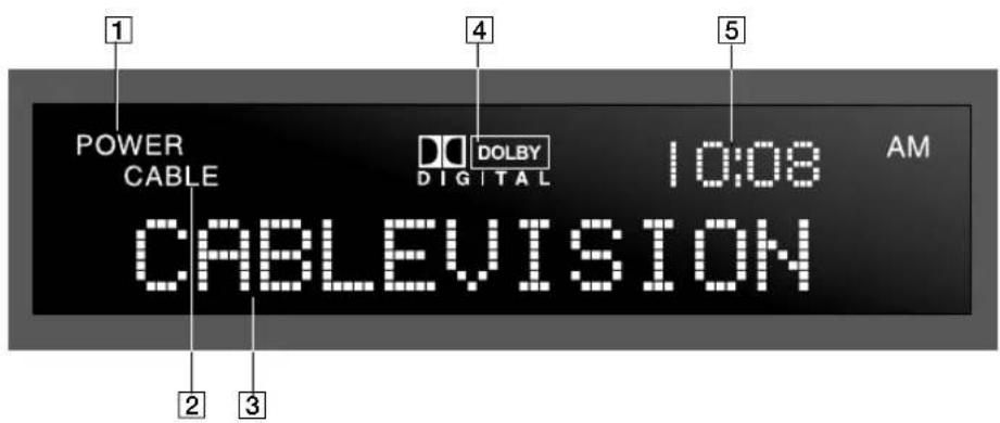
Indicator Description
| 1 | POWER | When lit, indicates the power is active. When not lit, indicates standby mode. |
| 2 | CABLE | When lit, indicates the unit is transmitting cable channels on its RF output. |
| 3 | Matrix Display | Displays channel number and name, program title, and messages. |
| 4 | DOLBY DIGITAL | When lit, a Dolby Digital program is being received. |
| 5 | Time | Displays current time. |
Rear Panel

Connection Description
| 1 | CABLE IN | Connects to Cablevision cable network signals using an RF coaxial cable. |
| 2 | TO TV/VCR | Outputs audio (variable) and video signals to the VHF/UHF (or RF) input on your TV or VCR using an RF coaxial cable. |
| 3 | i.LINK (2) | Used for connecting i.LINK-equipped devices (see the Cablevision user guide for details). |
| 4 | VCR CONTROL | Using an optional IR Repeater, outputs control signals to other devices (see the Cablevision user guide for details). |
| 5 | REMOTE RECEIVER | Inputs control signals to the Digital Network Receiver using an optional IR receiver. Useful for when the front panel cannot receive IR signals, such as when the unit is placed inside a cabinet. (For more information, contact Cablevision Customer Service.) |
| 6 | LINE OUT 1 (TV)AUDIO (VARIABLE)/VIDEO | Outputs audio (variable) and video (including the receiver's graphical user interface) signals to your TV using audio/video cables. |
| 7 | LINE OUT 2 (VCR)AUDIO (FIXED)/VIDEO | Outputs audio (fixed) and video signals to your VCR using audio/video cables. |
| 8 | LINE OUT 1 (TV)S VIDEO | Outputs video signals to your S VIDEO-equipped TV using an S VIDEO cable. |
| 9 | LINE OUT 2(VCR)S VIDEO | Outputs video signals to your S VIDEO-equipped VCR using an S VIDEO cable. |
| 10 | USB (TO PC ONLY) | Used for connecting USB-equipped PCs (see the Cablevision user guide for details). |
| 11 | DOLBY DIGITAL(AC-3) AUDIODIGITAL OUTCOAXIAL/OPTICAL | Outputs digital audio signals to the coaxial (COAXIAL) or optical (OPTICAL) digital input of your audio system. |
| 12 | USB | Used for connecting USB-equipped accessories (see the Cablevision user guide for details). |
| 13 | ACCESS CARD Slot | The slot in which the Access Card is inserted. |
| 14 | AC OUT | AC power switchable outlet (AC, 60Hz, 120V, 4.16A approx. 500W), for connecting your TV or VCR's AC power cord (see the Cablevision user guide for details). |
| 15 | AC IN | Inputs AC power from a power outlet using the AC power cord. |
Using the Remote Control (RM-Y806)
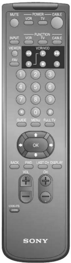
The following describes the Sony RM-Y806 remote control. If Cablevision supplied you with a different remote control, see the manual that came with that remote for details.
Buttons that are highlighted below can also be used to operate your TV and VCR after you've programmed the remote control. For details, see "Programming the Remote Control" on page 6.
Button Description
| MUTE | Mutes the sound. Press again or pressVOL to restore the sound. |
| VCR POWER | Turns the VCR on and off. |
| TV POWER | Turns the TV on and off. |
| CABLE POWER | Switches the Digital Network Receiver between active and standby modes. |
| INPUT | Selects (toggles through) the video inputs. |
| VCR FUNCTION | Activates the remote control for use with a VCR. |
| TV FUNCTION | Activates the remote control for use with a TV. |
| CABLE FUNCTION | Activates the remote control for use with the Digital Network Receiver. |
| VIEWER | Displays the Viewer screen (see the Cablevision user guide for details). |
| Rewind video. | |
| Play video. | |
| Fast-forward video. | |
| ● and ▶ | Record (press simultaneously). |
| Stop video. | |
| Pause video. | |
| FAV | Displays the Favorites screen (see the Cablevision user guide for details). |
| 0 – 9 | Selects a channel number directly. For example, to select channel 6, enter 006. Or you can enter 6 and then # (the ENTER button). |
| * | Selects the " *" indicated advertisement frame in the displayed screen. |
| # | ENTER button, used for confirming channel numbers (see 0-9 description above). |
| GUIDE | Displays the Guide screen (see the Cablevision user guide for details). |
| MENU | Displays the Menu screen (see the Cablevision user guide for details). |
continued
| Button Description | |
| FULL TV | Displays a full screen display of the last channel. |
| Arrows (↔ ↩ ↗) | Moves the highlight within menus and guides. |
| OK | Selects the highlighted item. |
| BACK | Displays the previous screen. |
| FWD | Displays the next screen. |
| LAST CH | Toggles between the last and current channel. |
| DISPLAY | Displays the Title Bar (see the Cablevision user guide for details). |
| VOL +/- | Adjusts the volume. |
| CH +/- | Changes the channel. |
| CODE SET | Used for programming the remote control to operate non-Sony video equipment. For details, see “Programming the Remote Control” on page 6. |
Programming the Remote Control
The remote control is preset at the factory to operate any Sony brand TV and VCR. If you have any other brand of TV or VCR, use the following procedures to program the remote to use the highlighted buttons shown on pages 5 and 6.
To program the remote
1 Turn to "Remote Control Programmable Codes" on page 12, and find the 3-digit code for your TV or VCR. If more than one code is listed, use the number listed first to complete the following procedures.
2 Press the CODE SET button.
3 Enter the 3-digit code using the 0-9 buttons.
4 Press the # button (located below the "9" button).
To check if the code works
1 Aim the remote control at the component you just programmed (e.g. aim at the TV and press TV POWER).
2 If the component responds, try the CH+ and CH- buttons. If the component responds, you're done.
If the component does NOT respond
Try programming the remote using the other codes listed for your brand. If you still cannot get your component to respond after trying all the codes, your component may not be compatible with this remote. If this happens, you must use your component's remote to operate it. Or, as an alternative, you can use the following instructions to program the Digital Network Receiver's remote to control the volume level.
Programming the Remote to Control Volume Level
If you cannot successfully program the Digital Network Receiver's remote to control your TV (as described on page 6), you can still use this remote to control the volume level (and MUTE) that is output from the Digital Network Receiver's audio LINE OUT 1 (TV) and TO TV/VCR jacks.
To program the remote to control the volume level
1 Press the CODE SET button.
2 Enter 200 using the 0-9 buttons.
3 Press the # button (located below the "9" button).
To check if the code works
1 Aim the remote control at the Digital Network Receiver.
2 Press the VOL+, VOL-, or MUTE button. If the volume level responds, you're done.
If you replace the TV or purchase a new one
Try programming the remote control as described on page 6, or you can continue to control only the volume level as described in this section.
Replacing Batteries in the Remote
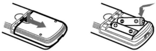
When the batteries need to be replaced, insert two size AA batteries by matching the + and - on the batteries to the diagram inside the battery compartment. Then replace the battery compartment lid.
natural_image
Two technical diagrams showing a smartphone with cable wrapping and battery mounting, no text or symbols present.Remove the batteries to avoid damage from possible battery leakage whenever you anticipate that the remote control will not be used for an extended period.
Handle the remote control with care. Avoid dropping it, getting it wet, or placing it in direct sunlight, near a heater, or where the humidity is high.
Introducing the Digital Network Receiver
Using the Wireless Keyboard (KI-W55CV)
The following describes the Sony KI-W55CV wireless keyboard. If Cablevision supplied you with a different keyboard, see the manual that came with that keyboard for details.
The wireless keyboard works like a regular keyboard and has additional buttons designed to control your Digital Network Receiver.
Buttons that are highlighted on the next page can also be used to operate your TV after you've programmed the wireless keyboard. For details, see "Programming the Wireless Keyboard" on page 10.
![POWER CABLE TV MENU VIEWER HW III CABLEVISION SONY CODE SPT TV CABLE L1 L2 INPUT RATE VOLUME CHANNEL ESC F1 F2 F3 F4 ◀◀ ▶ ▶▶ ■ ■ Guide Movies Events Inter- active Mail Option Full TV - 1 @ 2 3 $ 4 % 5 & 6 * 7 (8) 0 - - - ← Backspace Display Tab Q W E R T Y U I O P ( ) I [ ] / Last CH Caps Lock A S D F G H J K L : : OK/Enter ← Shift Z X C V B N M < > ? Shift ↑ Insert Delete Ctrl Alt * Back Fwd ← ↓ → Page Up Page Down](/content/2026/05/977834/images/cf443fb86be711cc7a521a0ef111d4410f6945c8b6e6c9f18b853359f22aadb0.jpg)
Button Description
| CABLE POWER Switches the Digital Network Receiver between active and standby modes. | |
| TV POWER Turns the TV on and off. | |
| MENU Displays the Menu screen (see the Cablevision user guide for details). | |
| VIEWER Displays the Viewer screen (see the Cablevision user guide for details). | |
| FAV Displays the Favorites screen (see the Cablevision user guide for details). | |
| CODE SET Used for programming the keyboard to operate non-Sony video equipment.For details, see “Programming the Wireless Keyboard” on page 10. | |
| TV/CABLE Activates the keyboard for use with the TV or the Digital Network Receiver. | |
| INPUT Selects (toggles through) the video inputs. | |
| MUTE | Mutes the sound. Press MUTE again or press VOL to restore the sound. |
| VOLUME Adjusts the volume. | |
| CHANNEL Changes the channel. | |
| ESC When entering text, brings cursor out from the text input window. | |
| F1 - F4 | See the Cablevision user guide for details. |
| ◀◀ ▶▶▶▶ ■ ■ | ◀◀ Rewind, ▶ Play, ▶▶ Fast-forward, ■ Stop, ■ Pause |
| Guide | Displays the Guide screen (see the Cablevision user guide for details). |
| Movies | Displays the Movies screen (see the Cablevision user guide for details). |
| Events | Displays the Events screen (see the Cablevision user guide for details). |
| Interactive | Displays the Online screen (see the Cablevision user guide for details). |
| Displays the Mail screen (see the Cablevision user guide for details). | |
| Option | Displays the Option screen (see the Cablevision user guide for details). |
| Full TV | Displays a full screen display of the last channel. |
| Display | Displays the Title Bar (see the Cablevision user guide for details). |
| Last CH | Toggles between the last and current channel. |
| Page Up Scrolls up the page. | |
| Page Down | Scrolls down the page. |
| Arrows (⇨⇨⇨) | Moves the highlight within menus and guides. |
| Backspace | When entering text, deletes the previous character. |
| OK/Enter ← | Selects the highlighted item. After inputting a channel number, confirms the number. When entering text, jumps to the beginning of the next text line. |
| Insert | When entering text, switches between inserting and overwriting text. |
| Delete When entering text, deletes the next character. | |
| Ctrl See the Cablevision user guide for details. | |
| Alt | See the Cablevision user guide for details. |
| * | Selects the “*” indicated advertisement frame in the displayed screen. |
| BACK | Displays the previous page. |
| FWD | Displays the next page. |
Programming the Wireless Keyboard
The keyboard is preset at the factory to operate any Sony brand TV. If you have any other brand of TV, use the following procedures to program the keyboard to use any of the highlighted buttons shown on page 8.
To program the keyboard
1 Set the keyboard's TV/CABLE switch to TV.
2 Turn to "Wireless Keyboard Programmable Codes" on page 13, and find the 3-digit code for your TV. If more than one code is listed, use the number listed first to complete the following procedures.
3 Press the CODE SET button.
4 Enter the 3-digit code for your TV using the 0-9 keys.
5 Press the OK/Enter key.
To check if the code works
1 Aim the keyboard at the TV and press TV POWER.
2 If the TV responds, try the VOLUME and MUTE buttons. If the TV responds, you're done.
☐ Try programming the keyboard using the other codes listed for your TV brand.
If you still cannot get your TV to respond after trying all the codes, your TV may not be compatible with this keyboard. If this happens, you must use your TV's remote to operate it.
If the TV does NOT respond
Positioning the Keyboard
The keyboard functions like a remote control. To use it, just point it at the front panel of the Digital Network Receiver. For best results, the keyboard should be used within 30 feet of the Digital Network Receiver, at no more than a 45^ angle.
Adjusting the Keyboard Legs
To raise the legs on the keyboard, use your finger to pry up the adjustable legs on the bottom of the keyboard until you feel them lock into place. To lower the keyboard, push each leg down until it snaps into the closed position.
Replacing Batteries in the Keyboard
When the batteries need to be replaced, insert two size AA batteries by matching the + and - on the batteries to the diagram inside the battery compartment. Then replace the battery compartment lid.
Remove the batteries to avoid damage from possible battery leakage whenever you anticipate that the keyboard will not be used for an extended period. Handle the keyboard with care. Avoid dropping it, getting it wet, or placing it in direct sunlight, near a heater, or where the humidity is high.
Remote Control Programmable Codes
TV Codes VCR Codes
Manufacturer Code Manufacturer Code
| Sony 101 Sony VHS 301 | |
| Akai 103 Sony 8mm 302 | |
| Bell & Howell 138 Sony Beta 303 | |
| Centurion 112 Bell & How 343 | |
| Coronad 113 Daewoo | 341 |
| Daewoo | 135, 136 |
| Emerson | 120, 121, 122, 123 |
| Fisher | 125 General Electric |
| General Electric | 102, 118 |
| Goldstar | 130 Goldstar |
| Hitachi | 131, 132 |
| JVC | 128, 129 |
| KTV | 133, 134 |
| Magnavox 111 | Magnavox |
| Marantz | 124 Mitsubishi 323, 324, 325, 3 |
| Panasonic | 116, 117, 118 |
| Pioneer | 137 Panasonic |
| Radio Shack | 115 |
| RCA 102, 104, 105, 106, 107, 108 | RCA |
| Samsung | 126, 127 |
| Sears | 119 Scott |
| Sharp | 114 |
| Symphonic | 139 Shintom 315 |
| Toshiba | 119 Sympho 338 |
| Zenith | 109, 110 |
| Emerson | 316, 317, 318, 319, 320 |
| Fisher | 330, 333, 334, 335 |
| Go Video | 339, 340 |
| Hitachi | 304, 305 |
| JVC | 314 |
| Kenwood | 314, 336, 332, 337 |
| 308, 309, 310 | |
| NEC | 336, 337 |
| Philips | 310 |
| Samsung | 313, 321, 322 |
| Sharp | 327, 328 |
| Teknica | 342, 338 |
| Toshiba | 311 |
| Zenith | 331 |
Wireless Keyboard Programmable Codes
TV Codes
Manufacturer Code Manufacturer Code
| Sony 101, 074, 077 NEC 103, 112, 001, 005, 006, 008, 020, 075, 025 | |||
| Admiral 102, 114, 109,055 Panasonic 118, 116, 117, 107, 064, 072, 058, 082, 140 | |||
| Akai 103, 020, 006 Philco 113, 103, 001, 008, 088, 061, 006, 090, | |||
| 050, 012, 098, 092, 100, 082, 020 | |||
| Bell & Howell(Mont. Ward) | 114, 109, 138,067 Philips 088, 001, 061, 006, 090, 012, 118, 119, 098, 092, 082, 020, 005, 057, 137 | ||
| Broksonic 68, 103, 112 Pioneer 137, 118, 119, 065, 026 | |||
| Centurion | 112, 045 | Portland | 103, 108, 088, 006, 090 |
| Coronado | 113, 088, 090 | Proton | 001, 031, 006, 077, 078, 090 |
| Craig | 122, 123, 120, 121, 007, 049, 050 | Quasar | 118, 107, 072, 058 |
| Croslex | 111. 030 | Radio Shack | 102, 112, 124, 123, 115, 050, 092, 025, 090 |
| Curtis Mathes | 103, 119, 123, 001, 006, 020, 090, 017, 031 | RCA/PROSCAN | 102, 103, 104, 105, 106, 107, 108, 061, 006, 071, 066, 087, 020, 090, 001, 062 |
| Daewoo | 001, 002, 003, 004, 005, 006, 008, 031, 032, 033, 034, 035, 036, 038, 046, 050, 052, 088, 092, 093, 135, 136, 103 | Realistic | 008, 025, 049, 050 |
| Daytron | 113, 001, 006, 020 | Samsung | 103, 126, 112, 113, 127, 088, 001, 061, 028, 043, 029, 081, 044, 048, 049, 090, 092, 051 |
| Emerson | 122, 113, 120, 121, 123, 103, 115, 088, 001, 090, 050, 083, 019, 030, 081, 020, 006, 025, 055, 023, 036 | Sanyo | 125, 089, 080, 062, 078, 013, 014 |
| Fisher | 125, 008, 080, 061, 015 | Scott | 123, 112, 001, 050, 019, 090, 006 |
| General Electric | 102, 118, 103, 107, 001, 061, 072, 050, 058, 017, 018, 006, 049, 019, 090 | Sears | 006, 008, 015, 019, 061, 080, 088, 089, 090, 091 |
| Goldstar | 103, 113, 112, 130, 088, 027, 001, 037, 010, 011, 042, 090, 039, 040, 092, 099 | Sharp | 114, 113, 115, 088, 090, 085, 024, 025, 069 |
| Hitachi 131, 113, 103, 132, 088, 006, 090, 071, 077, 070, 021, 022, 023, 025 | Signature 2000(Mont. Ward) | 114, 084, 006 | |
| JC Penney | 103, 102, 130, 107, 091, 092, 017, 020 | Sylvania | 020, 100, 111, 112, 103, 001, 061, 006, 012, 098, 092, 082 |
| JVC | 128, 129, 060, 016 | Symphonic | 123, 139, 002, 006, 090, 012, 020 |
| KTV | 020, 050, 061, 088, 133, 113, 103, 123, 134, 090 | Toshiba | 119, 114, 008, 091, 015, 075 |
| LXI (Sears) | 102, 103, 111, 125, 119,,1, 088, 06112, 061, 008, 015, 082 | Vidtech | 131, 103, 112, 006 |
| Magnavox | 111, 112, 113, 103, 025, 088, 061, 006, 090, 012, 098, 092, 100, 082, 020, 017, 103 | Wards | 113, 103, 115, 112, 088, 001, 090, 006, 036, 017, 018, 089, 080, 050, 039, 023, 078, 064, 055 |
| Marantz | 124, 094, 082, 020, 090 | Zenith | 109, 110, 076, 084, 006 |
| Mitsubishi | 124, 103, 112, 095, 075, 001, 006, 019, 020, 073, 066, 080, 088 | ||
Overview
This chapter includes illustrated instructions for setting up your Digital Network Receiver:
To Connect See Page
TV with RF Connector Only 16
TV and VCR with RF Connectors Only 17
TV with A/V Connectors 18
TV and VCR with A/V Connectors 19
Home Entertainment System 21
You can connect the Digital Network Receiver in a variety of configurations. The answers to the following questions will determine how you hook up and operate your components.
For example:
☐ What type of connectors do your TV and VCR have: S Video, A/V (Phono type), or RF coaxial?
☐ Do you plan to integrate the terminal with your audio or video system?
Detailed hook-up instructions are provided on the pages that follow.
Connecting the Digital Network Receiver
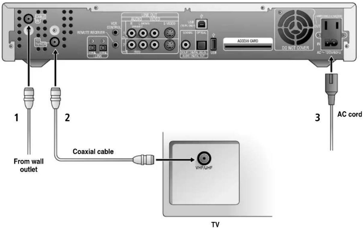
TV with RF Connector Only
1 Connect the coaxial cable from the wall outlet (Cablevision cable network signal) to the Digital Network Receiver's CABLE IN jack.
2 Connect the Digital Network Receiver's TO TV/VR jack to the TV's VHF/UHF IN (or RF IN) jack.
3 Connect one end of the AC power cord to the Digital Network Receiver's AC IN jack, then connect the plug end to an AC outlet.
4 Tune to channel 3 on your TV to see cable channels.
TV and VCR with RF Connectors Only
1 Connect the coaxial cable from the wall outlet (Cablevision cable network signal) to the Digital Network Receiver's CABLE IN jack.
2 Connect the Digital Network Receiver's TO TVVCR jack to the VCR's VHF/UHF IN (or RF IN) jack.
3 Connect the VCR's VHF/UHF OUT (or RF OUT) jack to the TV's VHF/UHF IN (or RF IN) jack.
4 Connect one end of the AC power cord to the Digital Network Receiver's AC IN jack, then connect the plug end to an AC outlet.
5 Set your VCR's channel switch (usually on the rear panel) to channel 3.

Connecting the Digital Network Receiver
TV with A/V Connectors
1 Connect the coaxial cable from the wall outlet (Cablevision cable network signal) to the Digital Network Receiver's CABLE IN jack.
2 Connect the Digital Network Receiver's LINE OUT 1 (TV) AUDIO/VIDEO jacks to the TV's AUDIO/VIDEO IN jacks.
3 Connect one end of the AC power cord to the Digital Network Receiver's AC IN jack, then connect the plug end to an AC outlet.

If your TV has an S VIDEO jack: For best picture quality, use an S VIDEO connection instead of the yellow video cable on your combined A/V cable. Using an S VIDEO cable, connect the Digital Network Receiver's S VIDEO OUT jack to the TV's S VIDEO IN jack. S VIDEO does not provide audio, so audio cables must still be connected to provide sound.
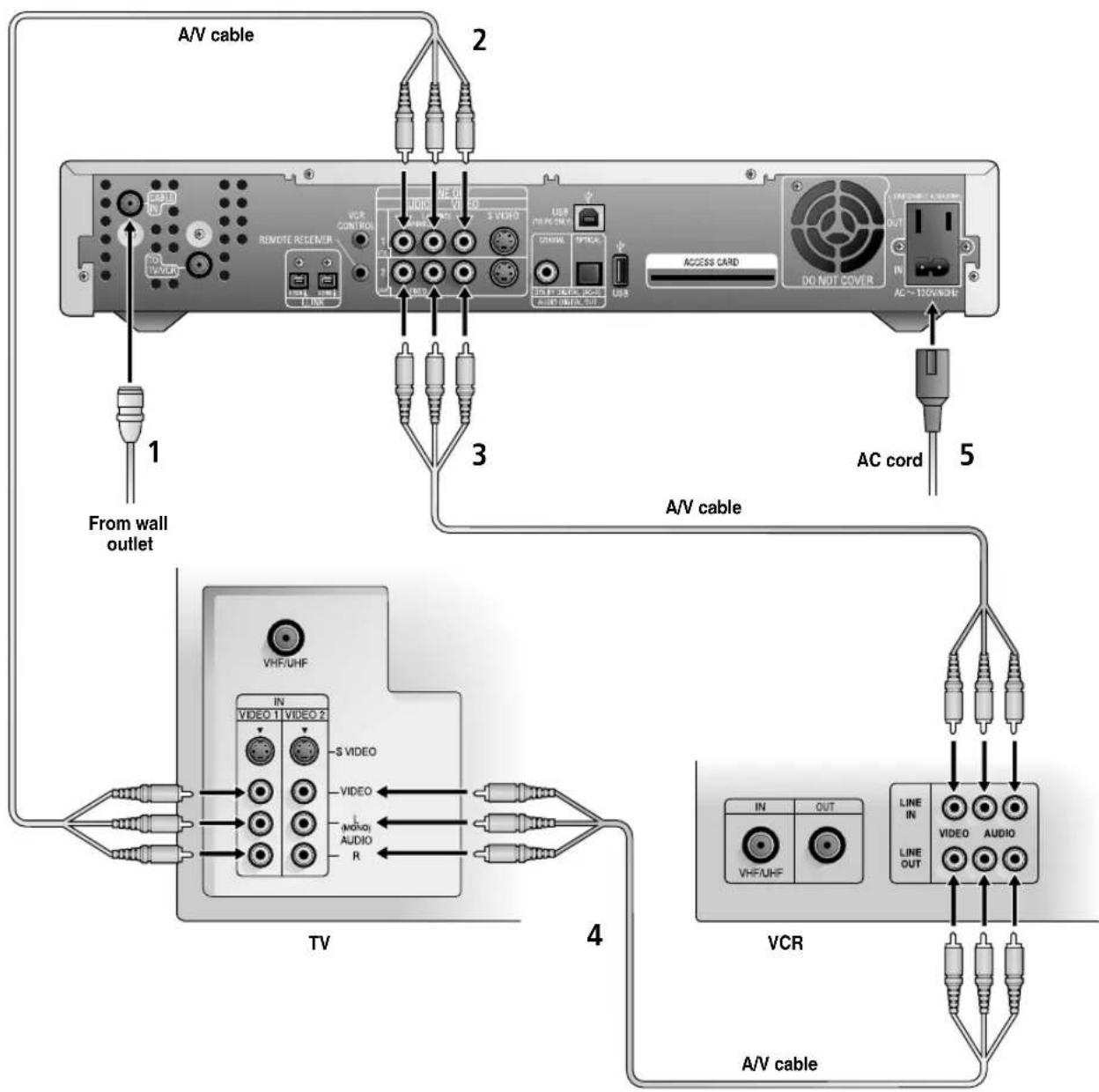
TV and VCR with A/V Connectors
See the illustration on the next page for details.
1 Connect the coaxial cable from the wall outlet (Cablevision cable network signal) to the Digital Network Receiver's CABLE IN jack.
2 Connect the Digital Network Receiver's LINE OUT 1 (TV) AUDIO /VIDEO jacks to the TV's AUDIO/VIDEO IN jacks.
3 Connect the Digital Network Receiver's LINE OUT 2 (VCR) AUDIO/VIDEO jacks to the VCR's AUDIO/VIDEO IN jacks.
4 Connect the VCR's AUDIO/VIDEO OUT jacks to the TV's AUDIO/VIDEO IN jacks.
If your TV has only one A/V input, the RF connection from VCR to TV is required for watching through the VCR.
5 Connect one end of the AC power cord to the Digital Network Receiver's AC IN jack, then connect the plug end to an AC outlet.
If your components have S VIDEO jacks: For best picture quality, use an S VIDEO connection instead of the yellow video cable on your combined A/V cable. Using an S VIDEO cable, connect the Digital Network Receiver's S VIDEO OUT jack to the TV's S VIDEO IN jack. S VIDEO does not provide audio, so audio cables must still be connected to provide sound.
Connecting the Digital Network Receiver
flowchart
graph TD
    A["TV"] -->|From wall outlet| B["AC cord"]
    B --> C["VCR"]
    C --> D["A/V cable"]
    D --> E["AC ~100MHz"]
    E --> F["DO NOT COVER"]
    F --> G["ACCESS CARD"]
    G --> H["USB"]
    H --> I["USB"]
    I --> J["USB"]
    J --> K["USB"]
    K --> L["USB"]
    L --> M["USB"]
    M --> N["USB"]
    N --> O["USB"]
    O --> P["USB"]
    P --> Q["USB"]
    Q --> R["USB"]
    R --> S["USB"]
    S --> T["USB"]
    T --> U["USB"]
    U --> V["USB"]
    V --> W["USB"]
    W --> X["USB"]
    X --> Y["USB"]
    Y --> Z["USB"]
    Z --> AA["USB"]
    AA --> AB["USB"]
    AB --> AC["USB"]
    AC --> AD["AC ~100MHz"]
    AD --> AE["DO NOT COVER"]
    AE --> AF["ACCESS CARD"]
    AF --> AG["USB"]
    AG --> AH["USB"]
    AH --> AI["USB"]
    AI --> AJ["USB"]
    AJ --> AK["USB"]
    AK --> AL["USB"]
    AL --> AM["USB"]
    AM --> AN["USB"]
    AN --> AO["USB"]
    AO --> AP["USB"]
    AP --> AQ["USB"]
    AQ --> AR["USB"]
    AR --> AS["USB"]
    AS --> AT["USB"]
    AT --> AU["USB"]
    AU --> AV["USB"]
Home Entertainment System
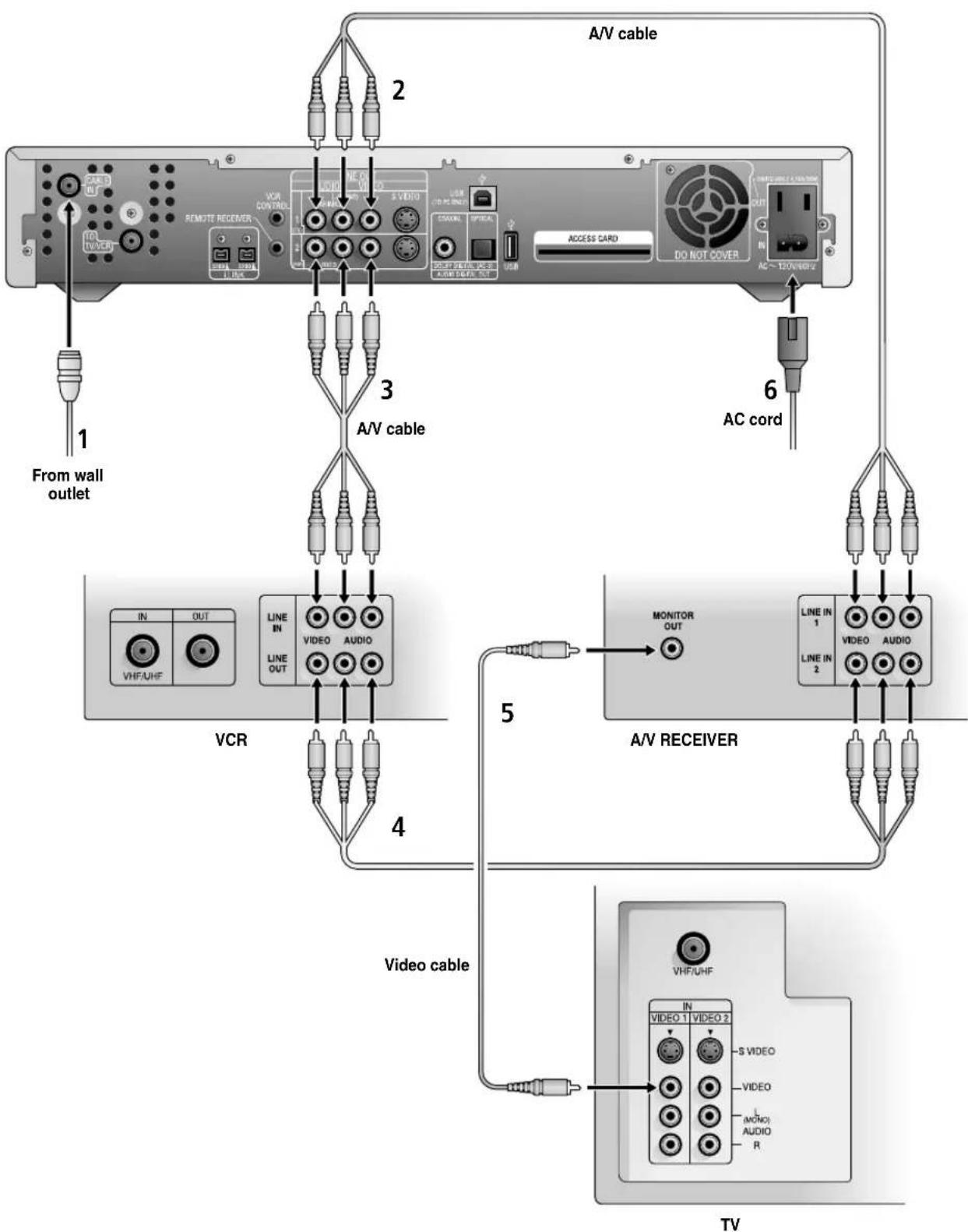
Connecting a Hi-Fi TV, Hi-Fi VCR, and an Audio/Video Receiver
See the illustration on the next page for details.
1 Connect the coaxial cable from the wall outlet (Cablevision cable network signal) to the Digital Network Receiver's CABLE IN jack.
2 Connect the Digital Network Receiver's LINE OUT 1 (TV) AUDIO/VIDEO jacks to the A/V Receiver's AUDIO/VIDEO IN jacks.
3 Connect the Digital Network Receiver's LINE OUT 2 (VCR) AUDIO /VIDEO jacks to the VCR's AUDIO/VIDEO IN jacks.
4 Connect the VCR's AUDIO/VIDEO OUTjacks to the A/V Receiver's AUDIO/VIDEO IN jacks.
5 Connect the A/V receiver's MONITOR OUT jack to the TV's VIDEO IN jack.
6 Connect one end of the AC power cord to the Digital Network Receiver's AC IN jack, then connect the plug end to an AC outlet.
If your components have S VIDEO jacks: For best picture quality, use an S VIDEO connection instead of the yellow video cable on your combined A/V cable. Using an S VIDEO cable, connect the Digital Network Receiver's VIDEO OUT jack to the TV's S VIDEO IN jack. S VIDEO does not provide audio, so audio cables must still be connected to provide sound. If your A/V receiver has digital audio in jacks, you can experience superior audio by connecting the Digital Network Receiver's digital audio out jack (COAXIAL or OPTICAL) to your A/V receiver's digital audio in jacks.
Connecting the Digital Network Receiver
flowchart
graph TD
    A["External Media"] -->|1 From wall outlet| B["VCR"]
    A -->|2 A/V cable| C["A/V cable"]
    A -->|3 A/V cable| D["A/V receiver"]
    A -->|4 Video cable| E["TV"]
    A -->|5 MONITOR OUT| F["A/V receiver"]
    A -->|6 AC cord| G["AC cord"]
    B --> H["IN OUT VHFAHF"]
    C --> I["LINE IN LINE OUT"]
    D --> J["LINE IN LINE OUT"]
    E --> K["IN VIDEO S VIDEO R"]
    F --> L["LINE IN 1 LINE IN 2"]
    G --> M["ACCESS CARD DO NOT COVER"]
    style A fill:#f9f,stroke:#333
    style B fill:#ccf,stroke:#333
    style C fill:#cfc,stroke:#333
    style D fill:#fcc,stroke:#333
    style E fill:#cff,stroke:#333
    style F fill:#ffc,stroke:#333
    style G fill:#fcc,stroke:#333
    style H fill:#fff,stroke:#333
    style I fill:#fff,stroke:#333
    style J fill:#fff,stroke:#333
    style K fill:#fff,stroke:#333
    style L fill:#fff,stroke:#333
    style M fill:#fff,stroke:#333
Setting Up the Remote Receiver
The optional Remote Receiver enables you to place the Digital Network Receiver out of sight, such as behind a cabinet door. Once the Remote Receiver is set up, the infrared signals are sent from your remote control or wireless keyboard to the Digital Network Receiver via the Remote Receiver.
To connect the Remote Receiver
1 Connect the Remote Receiver to the Digital Network Receiver's REMOTE RECEIVER jack.

2 Place the Remote Receiver on top of the TV, with the IR window facing out as shown.
After the Remote Receiver is set up, aim your remote control or wireless keyboard at the Remote Receiver on top of the TV.
Other Information
Troubleshooting
| Problem Possible Remedies | |
| Cannot display cable channels | If you connected the Digital Network Receiver to your TV with an RF connection (as described on page 16) you need to tune your TV to channel 3 in order to see cable channels.If you connected the Digital Network Receiver to your VCR with an RF connection (as described on page 17) you need to set your VCR's RF channel switch (usually on the rear panel) to channel 3 in order to see cable channels.If channel 3 is not an empty channel in your channel line-up, you can set the TV or VCR to channel 4, but you must also change the Digital Network Receiver's RF channel to channel 4 in order to see cable channels. For details see, “Changing the Digital Network Receiver's RF Output Channel” on page 26. |
| Sony remote control (RM-Y806) does not operate | Batteries could be weak. Replace the batteries (see page 7).Check the orientation of the batteries (see page 7).Make sure you press the FUNCTION button (TV, VCR, CABLE) of the device you want to control (see page 5).If you are trying to control a TV or VCR that is not a Sony brand, you must first program the remote to operate these devices (see page 6).Locate the TV at least 3-4 feet away from fluorescent lights. |
| Sony wireless keyboard (KI-W55CV-Y806) does not operate | Batteries could be weak. Replace the batteries (see page 7).Check the orientation of the batteries (see page 7).Make sure the FUNCTION switch (TV, CABLE) is set to the device you want to control (see page 5).If you are trying to control a TV that is not a Sony brand, you must first program the keyboard to operate your TV (see page 8).Locate the TV at least 3-4 feet away from fluorescent lights. |
| Volum e p roblems when recording to VCR | If you connected your VCR to the Digital Network Receiver's TO TV/VCR or LINE OUT 1 (TV) AUDIO /VIDEO jack and you programmed the remote to control the Digital Network Receiver's volume as described on page 7, be sure to do the following when recording:Maximize the Digital Network Receiver's volume.Make sure MUTE is off.Make sure you do not change these volume controls while you are recording. |
Changing the Digital Network Receiver's RF Output Channel
If you connected the Digital Network Receiver to your TV or VCR using an RF connection (as described on pages 16 and 18), you need to set the RF output channel of the Digital Network Receiver to match the RF channel (channel 3 or 4) of the cable service provided in your area. The Digital Network Receiver is shipped with its RF output channel set to channel 3.
To set the RF output channel of the Digital Network Receiver
1 Using the buttons on the front panel, first press the STANDBY ⏻ button to turn off the Digital Network Receiver, which puts the unit in standby mode.
2 To set the Digital Network Receiver to channel 3 or 4:
To Use RF Press These Front Panel Buttons Sequentially
| Channel 3 | (cursor up), (cursor right), (cursor down) |
| Channel 4 | (cursor up), (cursor right), (cursor up) |
3 Do one of the following:
☐ If you connected the Digital Network Receiver to your TV (as described on page 16), tune your TV to channel 3 to see cable channels.
☐ If you connected the Digital Network Receiver to your VCR (as described on page 17), set your VCR's RF channel switch (usually on the rear panel) to channel 3 to see cable channels.
Specifications
Inputs and Outputs
| Cable In Input 75-ohm F-connector Female (1) | |
| To TV/VCR Output 75-ohm F-connector Female (1) | |
| Video Input Composite Video (1, front panel) | |
| Output S-Video 4-pin mini DIN (2)Composite Video (2) | |
| Audio Input Stereo L/R (1, front panel) | |
| Output Stereo L/R (2) | |
| i.LINK Input/Output 4-pin S200 i.LINK terminal (2) | |
| USB Input/Output For peripheral (1 front panel,1 rear panel)For PC (1, rear panel) | |
| Remote Receiver Input Optional IR Receiver (IR-R55 only) | |
| VCR Control Output (See the Cablevision Service Guide) | |
| Audio Digital Out | Output Coaxial (1) |
| Dolby Digital(AC-3)/PCM | Optical Rectangular (1) |
| AC Input Supplied AC power cord | |
| Output AC 60 Hz, 120 V, 4.16A (approx.500 W) Switchable | |
General
| Input frequency | 54 MHz – 864 MHz |
| Output frequency | 5 MHz – 42 MHz, 61 MHz – 72 MHz |
| Power requirements | AC 60 Hz 120 V 1.0 A |
| Power consumption | 50W Typical, 120 V |
| Operating temperature | 5°C to 35°C (35°F to 51°F) |
| Operating relative humidity | 45% to 85% |
| Dimensions | Approx. 430 × 80 × 374 mm (w/h/d)(Approx. 16-15/16 × 3-1/8 × 14-3/4 inches)including projecting parts and controls |
| Mass | Approx. 4.6 kg (10.1 lbs) |
Accessories
Supplied
AC power cord (1)
Optional Sony Branded Digital Network Receiver Accessories
Remote Commander, RM-Y806 (includes AA batteries)
Wireless Keyboard, KI-W55CV (includes AA alkaline batteries)
IR Remote Receiver, IR-R55
Index
# (ENTER), on remote 5 0 - 9, on remote 5
A
AC IN connector 4 AC OUT connector 4 ACCESS CARD slot 4 Affinity Card slot 2 Alt, on keyboard 9 arrow buttons, on keyboard 9 arrows, on remote 6 audio/video receiver, connecting 21
B
BACK, on keyboard 9 BACK, on remote 6 Backspace, on keyboard 9 batteries in remote control 7 inserting in keyboard 11 inserting in remote 7
C
CABLE FUNCTION, on remote 5 CABLE IN connector 4 CABLE indicator 3 CABLE POWER, on keyboard 9 CABLE POWER, on remote 5 camcorder, connecting 3 card slot, for Access Card 4 card slot, for Affinity Card 2 CH +/-, on remote 6 changing channels, on remote 6 channel 3 or 4, setting 25, 26 CHANNEL, on keyboard 9 channels, changing, on remote 6 CODE SET, on keyboard 9 CODE SET, on remote 6, 7 connecting camcorder 3 digital still camera 3 hi-fi TV, VCR, audio receiver
with A/V connectors 21
home entertainment system 21
TV and VCR with A/V connectors 19
TV and VCR with RF connectors 17
TV with A/V connectors 18
TV with RF connector 16 USB devices 3
controlling VCR 4
Ctrl, on keyboard 9
D
Delete, on keyboard 9 digital still camera, connecting 3 Display, on keyboard 9 DISPLAY, on remote 6 DOLBY DIGITAL indicator 3 DOLBY DIGITAL OUT connectors 4, 21 door, for front panel inputs 2
E
ESC, on keyboard 9 Events, on keyboard 9
F
F1 - F4 (function keys), on keyboard 9 FAST-FORWARD, on remote 5 FAV, on keyboard 9 FAV, on remote 5 front panel 2 display, illustrated 3 illustrated 2 FULL TV, on front panel 2 FULL TV, on keyboard 9 FULL TV, on remote 6 FWD, on keyboard 9 FWD, on remote 6
G
Guide, on keyboard 9 GUIDE, on remote 5
|
i.LINK connectors 4
INPUT, on keyboard 9
INPUT, on remote 5
Insert, on keyboard 9
IR Repeater, using 4
L
Last CH, on keyboard 9
LAST CH, on remote 6
line inputs, front panel 2, 3
LINE OUT connectors 4
M
Mail, on keyboard 9
MENU, on front panel2
MENU, on keyboard 9
MENU, on remote 5
Movies, on keyboard 9
MUTE, on keyboard 9
MUTE, on remote 5
0
OK, on remote 6
OK/Enter, on keyboard 9
Option, on keyboard 9
P
Page Down, on keyboard 9
Page Up, on keyboard 9
PAUSE, on remote 5
PLAY, on remote 5
POWER indicator 3
problems, correcting 25
problems, troubleshooting 25
programming
remote control 6
R
rear panel, illustrated 4
remote control
illustrated 5
inserting batteries 7
programmable codes 12
programming 6
REMOTE RECEIVER 23
REMOTE RECEIVER connector 4
replacing batteries
in remote control 7
REWIND, on remote 5
RF channel, setting25, 26
S
S VIDEO OUT connectors 4
setting, channel 3 or 4 25, 26
slot, for Affinity Card 2
slot, for connecting Access Card 4
standby indicator 3
STANDBY, on front panel 2
STOP, on remote 5
T
Time indicator 3
TO TV/VCR connector 4
troubleshooting 25
TV FUNCTION, on remote 5
TV POWER on remote 6
TV POWER, on keyboard 9
TV POWER, on remote 5
TV with A/V connectors 18, 19, 21
TV with RF connector 16, 17
TV/CABLE, on keyboard 9, 10
U
USB connectors, rear panel 4
USB devices, connecting 2, 3
v
VCR CONTROL 4
VCR FUNCTION, on remote 5
VCR POWER, on remote 5
VCR with A/V connectors 19, 21
VCR with RF connector 17
VCR, controlling 4
VIEWER, on keyboard 9
VIEWER, on remote 5
VOL +/-, on remote 6
volume
adjusting 2
Other Information
volume, adjusting, on remote 6
VOLUME, on keyboard 9
W
wireless keyboard
illustrated 8
programming 10
replacing batteries 11
- Digital Network Receiver™
- Sony Software License Agreement
- License and Restrictions
- Intellectual Property
- Termination
- Export Requirements and U.S. Government Restricted Rights
- Limited Warranty
- General
- WARNING
- CAUTION
- Note on Cleaning the Unit
- Note to CATV System Installer
- Trademark, Copyright, and License Information
- Macrovision
- Features May Change
- i.LINK
- Customer Service
- Regulatory Information
- NOTIFICATION
- Safety Instruction for Pluggable Equipment
- Safety
- Installing
- Owner's Record
- Important Safety Notice
- Use
- Power Sources
- Overloading
- Object and Liquid Entry
- Cleaning
- Installation
- Water and Moisture
- Accessories
- Ventilation
- Power-Cord Protection
- Lightning
- Service
- Damage Requiring Service
- Servicing
- Safety Check
- Contents
- Introducing the Digital Network Receiver
- Connecting the Digital Network Receiver
- Other Information
- Unpacking
- Supplied Items
- Items Supplied Separately by Cablevision
- Optional Items
- Front Panel Controls and Indicators
- Front Panel Inputs
- Front Panel Display
- Using the Remote Control (RM-Y806)
- To program the remote
- To check if the code works
- If the component does NOT respond
- To program the remote to control the volume level
- If you replace the TV or purchase a new one
- Using the Wireless Keyboard (KI-W55CV)
- 3
- Programming the Wireless Keyboard
- To program the keyboard
- If the TV does NOT respond
- Positioning the Keyboard
- Adjusting the Keyboard Legs
- Remote Control Programmable Codes
- Wireless Keyboard Programmable Codes
- TV Codes
- Overview
- To Connect See Page
- TV with RF Connector Only
- TV and VCR with RF Connectors Only
- TV with A/V Connectors
- TV and VCR with A/V Connectors
- Home Entertainment System
- Setting Up the Remote Receiver
- To connect the Remote Receiver
- To set the RF output channel of the Digital Network Receiver
- Specifications
- Inputs and Outputs
- Supplied
- Optional Sony Branded Digital Network Receiver Accessories
- Index
- A
- B
- C
- D
- E
- F
- G
- |
- L
- M
- 0
- P
- R
- S
- T
- U
- v
- W
Brand : SONY
Model : DHG-M55CV
Category : Digital Receiver