1750 - Measuring instrument FLUKE - Free user manual and instructions
Find the device manual for free 1750 FLUKE in PDF.


| Product Type | Three-Phase Power Quality Recorder |
| Brand | Fluke |
| Model | 1750 |
| Dimensions | 300 x 200 x 80 mm |
| Weight | 2 kg (approx.) |
| Power Supply | 100-240 V AC, 50/60 Hz; internal battery |
| Input Channels | 4 voltage (up to 600 V), 4 current (via clamps) |
| Measurement Functions | Voltage, current, frequency, harmonics, flicker, dips/swells, transients, power, energy |
| Data Storage | Internal memory (8 GB) and USB/SD card |
| Display | Color LCD touchscreen |
| Communication | USB, Ethernet, Wi-Fi optional |
| Compliance | IEC 61000-4-30 Class A |
| Safety Rating | CAT IV 600 V / CAT III 1000 V |
| Operating Temperature | 0°C to 50°C |
| Humidity Range | 0% to 95% non-condensing |
| Maintenance | Clean with dry cloth; periodic calibration recommended |
| Included Accessories | Voltage leads, current clamps, power cord, quick start guide |
| Warranty | 3 years |
Frequently Asked Questions - 1750 FLUKE
User questions about 1750 FLUKE
0 question about this device. Answer the ones you know or ask your own.
Ask a new question about this device
Download the instructions for your Measuring instrument in PDF format for free! Find your manual 1750 - FLUKE and take your electronic device back in hand. On this page are published all the documents necessary for the use of your device. 1750 by FLUKE.
USER MANUAL 1750 FLUKE
Each Fluke product is warranted to be free from defects in material and workmanship under normal use and service. The warranty period is one year and begins on the date of shipment. Parts, product repairs, and services are warranted for 90 days. This warranty extends only to the original buyer or end-user customer of a Fluke authorized reseller, and does not apply to fuses, disposable batteries, or to any product which, in Fluke's opinion, has been misused, altered, neglected, contaminated, or damaged by accident or abnormal conditions of operation or handling. Fluke warrants that software will operate substantially in accordance with its functional specifications for 90 days and that it has been properly recorded on non-defective media. Fluke does not warrant that software will be error free or operate without interruption.
Fluke authorized resellers shall extend this warranty on new and unused products to end-user customers only but have no authority to extend a greater or different warranty on behalf of Fluke. Warranty support is available only if product is purchased through a Fluke authorized sales outlet or Buyer has paid the applicable international price. Fluke reserves the right to invoice Buyer for importation costs of repair/replacement parts when product purchased in one country is submitted for repair in another country.
Fluke's warranty obligation is limited, at Fluke's option, to refund of the purchase price, free of charge repair, or replacement of a defective product which is returned to a Fluke authorized service center within the warranty period.
To obtain warranty service, contact your nearest Fluke authorized service center to obtain return authorization information, then send the product to that service center, with a description of the difficulty, postage and insurance prepaid (FOB Destination). Fluke assumes no risk for damage in transit. Following warranty repair, the product will be returned to Buyer, transportation prepaid (FOB Destination). If Fluke determines that failure was caused by neglect, misuse, contamination, alteration, accident, or abnormal condition of operation or handling, including overvoltage failures caused by use outside the product's specified rating, or normal wear and tear of mechanical components, Fluke will provide an estimate of repair costs and obtain authorization before commencing the work. Following repair, the product will be returned to the Buyer transportation prepaid and the Buyer will be billed for the repair and return transportation charges (FOB Shipping Point).
THIS WARRANTY IS BUYER'S SOLE AND EXCLUSIVE REMEDY AND IS IN LIEU OF ALL OTHER WARRANTIES, EXPRESS OR IMPLIED, INCLUDING BUT NOT LIMITED TO ANY IMPLIED WARRANTY OF MERCHANTABILITY OR FITNESS FOR A PARTICULAR PURPOSE. FLUKE SHALL NOT BE LIABLE FOR ANY SPECIAL, INDIRECT, INCIDENTAL, OR CONSEQUENTIAL DAMAGES OR LOSSES, INCLUDING LOSS OF DATA, ARISING FROM ANY CAUSE OR THEORY.
Since some countries or states do not allow limitation of the term of an implied warranty, or exclusion or limitation of incidental or consequential damages, the limitations and exclusions of this warranty may not apply to every buyer. If any provision of this Warranty is held invalid or unenforceable by a court or other decision-maker of competent jurisdiction, such holding will not affect the validity or enforceability of any other provision.
Fluke Corporation
P.O. Box 9090
Everett, WA 98206-9090
U.S.A.
Fluke Europe B.V.
P.O. Box 1186
5602 BD Eindhoven
The Netherlands
Table of Contents
Title
Page
Introduction....1
Contacting Fluke 2
Safety Information 3
Accessories 4
Features....5
Applying the Front Panel Decal....7
Charging the PDA Battery 9
Installing the Software 9
Installing Power View on the PDA 9
Language Selection 10
PC System Requirement for Power Analyze.... 10
Installing Power Analyze 10
Installing the Power Recorder at a Facility.... 11
Work Flow....11
Installing the Recorder 11
Connecting the Recorder to the Wiring.... 12
Verifying Your Connection....13
Finishing Up....13
Managing Recorded Data 14
Power Type Diagrams 14
Communicating with the Recorder Using Power View.... 25
Navigating in Power View on the PDA.... 26
Power View Menus 26
Icons on the Menu Bar 27
Menu Tree....28
Home Screen....29
Downloading Data and Erasing Memory 31
Auto Download 31
PDA Download 32
Viewing Live Data.... 35
Scope Screen 36
Meter Screen.... 36
Phasor Screen 37
Harmonics Screen.... 37
Trend Screen....38
Viewing Phases 38
Setting Up the Recorder.... 39
Setting the Clock 40
Probe Detect 40
Setting the IP Address 41
Adding a Measurement Description.... 41
Configure Nominal Power Values.... 42
Using Phase Swap 42
Setting the Volts and Current Ratio.... 43
Assign Recorder Name and Password....43
Setting the Snapshot Period - Periodic Waveform Capture Setting ...... 44
Change Display Language and Phase Identifier 45
Working with Annotations 45
Using Image or Voice Annotations.... 47
Inserting Image or Voice Annotations 47
Turn off the Recorder 47
Cleaning and Maintenance....48
Regulatory Information for Wireless Communication 48
Specifications for the System: Recorder and Power Analyze Software ..... 49
General Specifications.... 49
Input Specifications....50
Synchronization and Sampling....50
Voltage and Current Measurements 50
Voltage and Current Measurement Accuracy 50
Transient Voltage (Impulse)....51
Dip (Sag) and Swell Measurements 51
Power and PF Measurement....51
External Interface Specifications.... 52
Environmental and Safety Specifications.... 52
List of Tables
Table
Title
- Symbols.... 4
- Standard Accessories 4
- Input Terminals and Controls.... 6
List of Figures
Figure
Title
- Fluke 1750 Power Recorder.... 5
- Applying the Front Panel Decal....7
- Connecting the Supplemental Ground Terminal 8
- One Phase Plus Neutral....15
- One-Phase IT No Neutral....16
- One-Phase Split Phase.... 17
- Three-Phase Wye 18
- Three-Phase Delta 19
- Three-Phase IT 20
- Three-Phase High Leg.... 21
- Three-Phase Open Leg 22
- 2-Element Delta .... 23
- 2 12 -Element Wye..... 24
- Connecting to the Recorder.... 25
- Power View Menu Tree 28
Introduction
The Fluke 1750 Power Recorder is a comprehensive yet easy to use system for power quality investigations. The 1750 Power Recorder, referred to hereafter as simply “the Recorder or the Product,” consists of a power recorder instrument, a wireless handheld Personal Digital Assistant (PDA) for control and setup, and a powerful yet easy to use PC application, Power Analyze. Four 400 A current probes are provided as standard equipment (not included in Basic version). A wide range of flexible and clamp-on current probes are available from Fluke.
Key features of the 1750 Power Recorder are:
- No PC needed for setup
Using the included wireless-enabled Personal Digital Assistant (PDA) as a controller, you do not need a PC to configure the Recorder, troubleshoot connections, preview data, or download the recorded data. Downloaded data goes onto the SD memory card plugged into the 1750, not directly to the PDA. The range of the PDA with the wireless link is about 5 meters (16 feet) from the Recorder. This range is dependent on the electrical interference in the location.
- Simplified test lead connections to the power network
Simply connect a voltage probe to a conductor on each phase that you want to record. On the current inputs, the Recorder automatically identifies what type of probe is connected. The Recorder then configures its measurement system appropriately for the model of current probe you are using.
- Connection diagrams for the supported power network configurations (delta, Wye, and others) appear on the handheld PDA controller. Once you make connections, you can view live readings and a phasor diagram on the PDA to confirm the connections. If a phase channel is wired incorrectly, you can swap the phase to another channel by changing an internal Recorder setting using the PDA, and then reconfirm correct readings.
- Internal Uninterruptible Power Supply (UPS)
An internal NiMH (Nickel-Metal-Hydride) battery pack and charging system maintain data capture continuity through power interruptions of approximately 5 minutes or less.
• Automatic disturbance capture
The Recorder uses an automatic, self-learning threshold routine, which means you do not have to set any event threshold limits before you start recording. You detect and display power quality events (disturbances) using the Power Analyze software on a PC after the event has been captured. You define thresholds for events after data is stored on the PC. This is called the "event detector" in the software. It does not make permanent changes to the data file, so you can experiment with different thresholds after the fact without worrying about losing data.
With these features, there is little else required to set up and start recording the data to conduct a power quality survey. Should you want to extensively analyze collected data, the procedures described later in this manual review the transfer of data from the Recorder to the PDA, and finally to a PC. Data may then be analyzed using Power Analyze on a PC. Extensive online help is provided in the Power Analyze software on the product CD shipped with the Recorder.
Contacting Fluke
To contact Fluke, call one of the following telephone numbers:
• Technical Support USA: 1-800-44-FLUKE (1-800-443-5853)
• Calibration/Repair USA: 1-888-99-FLUKE (1-888-993-5853)
• Canada: 1-800-36-FLUKE (1-800-363-5853)
• Europe: +31 402-675-200
• Japan: +81-3-3434-0181
• Singapore: +65-738-5655
• Anywhere in the world: +1-425-446-5500
Or, visit Fluke's website at www.fluke.com.
To register your product, visit http://register.fluke.com.
To view, print, or download the latest manual supplement, visit http://us.fluke.com/usen/support/manuals.
To contact Technical Support: fpqsupport@fluke.com or 888-257-9897
Safety Information
See the Specifications section for a full agency compliance list. Table 1 lists symbols that appear on the Recorder and in this manual.
⚠ Warning
To prevent possible electrical shock, fire, or personal injury:
- Carefully read all instructions.
- Do not work alone.
- Do not use the Product around explosive gas, vapor, or in damp or wet environments.
- Use only insulated current probes, test leads, and adapters as supplied with the Product.
- Examine the case before you use the Product. Look for cracks or missing plastic. Carefully look at the insulation around the terminals.
- Remove all probes, test leads, and accessories that are not necessary for the measurement.
- Make sure the ground conductor in the mains power cord is connected to a protective earth ground. Disruption of the protective earth could put voltage on the chassis that could cause death.
- Only use probes, test leads, and accessories that have the same measurement category, voltage, and amperage ratings as the product.
- Do not use exposed metal BNC or banana plug connectors.
- Do not put metal objects into connectors.
- Do not operate the Product with covers removed or the case open. Hazardous voltage exposure is possible.
- There are no user-replaceable parts in the Product. Have an approved technician repair the Product.
- Use the Product only as specified, or the protection supplied by the Product can be compromised.
Table 1. Symbols
| Symbol | Meaning Symbol Meaning | ||
 | Hazardous voltage. Risk of electrical shock. |  | Risk of danger. Important information. See manual. |
| [SOYA] | Canadian Standards Association.[Note: Canadian and US.] | [HXBT] | Protective conductor terminal. |
| CAT III | CAT III equipment is designed to protect against transients in equipment in fixed-equipment installations, such as distribution panels, feeders and short branch circuits, and lighting systems in large buildings. | CAT IV | CAT IV equipment is designed to protect against transients from the primary supply level, such as an electricity meter or an overhead or underground utility service. |
 | Do not dispose of this product as unsorted municipal waste. Contact Fluke or a qualified recycler for disposal. | ||
Accessories
Table 2 describes the standard accessories that ship with the Recorder.
Table 2. Standard Accessories
| Description Part Number | |
| Ethernet cable, 3 meters, yellow 2402854 | |
| Colored plastic clips for test leads (32 clips, 8 colors, 4 clips each color) | 2157607 |
| Model TLS430, test lead set including cable and clips 2157713 | |
| Secure Digital (SD) Memory Card for downloading data Call for details | |
| Model 3140R, 400 A Clamps (4-not included with Basic version) 2277216 | |
| AC power cord, 3 meters 2441360 | |
| Personal Digital Assistant (PDA) with USB cable and accessories | 2386780 |
| CD-ROM Manuals and Software 2386771 | |
| 1750 Getting Started Guide 2386767 | |
| Sheet of Front Panel Decals 2436261 | |
| Sets of international ac power plug adapters for the PDA charger 2583479 | |
| International adapters for the Recorder power cord 2441372 |
You can also order the following optional accessories. For more information about accessories, see Contacting Fluke earlier in this manual. An updated list is always available on www.fluke.com.
• CS1750/1760 Case Polyester, for Fluke 1750 & 1760
- Fluke-1750/Case Transit Case, Molded, Flk-1750 and 1760
• 4006 RPM, Security CBL, Steel, 6 ft. Looped Lockable
• 4003 RPM, Shipping Caddy with Wheels
• 4005 RPM, Shipping Container, Reusable
• 4005 RPM, Shipping Container, Reusable
- Replacement Voltage Lead Set
- Clamp-on Current Transformers (i5s-PR 5 Amp, Clamp with 10 ft. Cable,
- i40s-PR 40 Amp, Clamp with 10 ft. Cable), Flex CT 24 in, 3140R Current Clamp, 400 Amp
- Flexible Current Transformers 3210-PR-TF 1000 Amp, Flex CT 24 IN, 3310-PR-TF 5000 Amp, Flex CT 24 in., 3312-PR-TF 5000 Amp, Flex CT 48 in.
• Interface and Extension Cables
3570 CT Cable
- Replacement/Additional Memory card: Fluke-1750/MC2GB 1750 2GB Secure Digital Memory Card
Features
The Recorder front panel is illustrated in Figure 1 and described in Table 3.
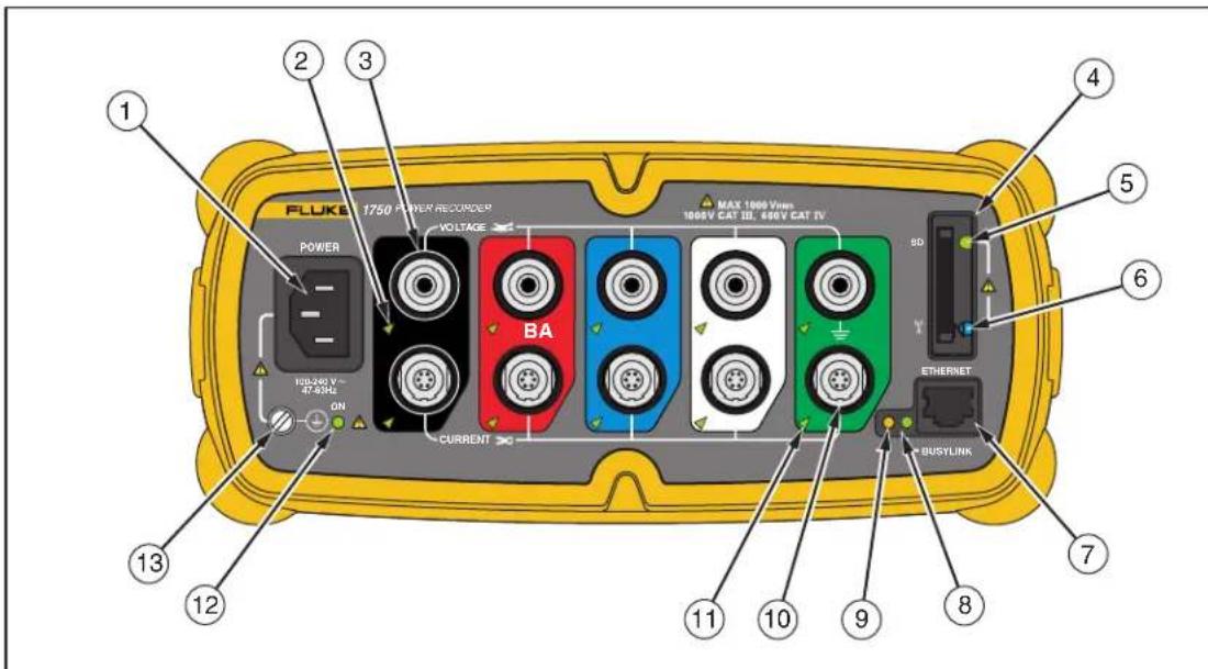
Figure 1. Fluke 1750 Power Recorder
azd09f.eps
Caution
Connecting the supplemental ground terminal and the line cord safety ground to different ground potentials creates a ground loop that can damage the Recorder.
Table 3. Input Terminals and Controls
| Number | Description |
| 1 Standard 120/240 V 50/60 Hz power input for Recorder power | |
| 2 Voltage indicatorSteady Voltage is present, not overloadedBlinking Voltage overload (overload threshold 1100 V) | |
| 3 Five voltage measurement inputs | |
| 4 | Removable Secure Digital (SD) memory card for transfer of large quantities of data. You can remove the card from the Recorder, insert in the PDA and transfer data to the PC via the "synchronize data" feature of the PDA. A USB SD card reader may also be used. |
| 5 SD status indicatorBlinking green Reading from SD card – do not remove the cardBlinking orange Writing to SD card – do not remove the cardOff No active SD card operation – you can safely remove the card | |
| 6 | Wireless Controller Status IndicatorBlinking Wireless controller communicatingOff Inactive |
| 7 | Ethernet port. TCP/IP via Ethernet is used to connect the Recorder to a PC for downloading recorded data, and for configuring the Recorder when not using the PDA. This is the recommended method of data transfer due to its speed and reliability. |
| 8 Busy IndicatorBlinking Network is busy | |
| 9 Link indicatorOff No linkSteady Link PresentBlinking Communicating with PC | |
| 10 Current Measurement Terminals (5) | |
| 11 Current indicatorSteady Current probe in normal rangeBlinking >110 % of probe range, use a higher range probeOff Current insufficient to measure | |
| 12 Power LEDSteady green AC input power normal, instrument is not booted or lockedGreen/orange blinking RecordingBlinking red Recorder running on UPS | |
| 13 Ground TerminalConnecting the supplemental ground terminal and the line cord safety ground to different ground potentials creates a ground loop that can damage the Recorder. To avoid this, use the supplemental ground terminal only when no protective earth ground connection exists through the line power cord. If there is any chance that a safety ground connection does exist through the line power cord connection, make sure to connect the supplemental ground terminal only to the ground system used by the ac receptacle that powers the Recorder. See Figure 3. | |
Applying the Front Panel Decal
Self-adhesive front panel decals are supplied with the 1750. The supplied decals correspond to the wiring color codes used in the USA, Europe and UK (new), Europe (old), UK, Canada, and China. Apply the decal appropriate for your local wiring codes around the current and voltage inputs as shown in Figure 2.
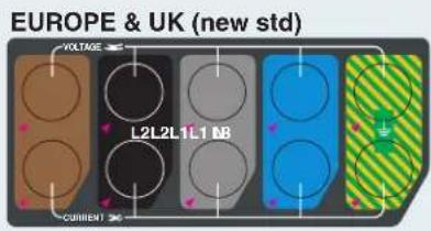
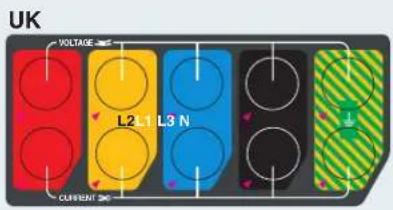
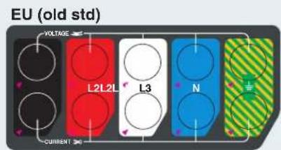
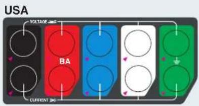
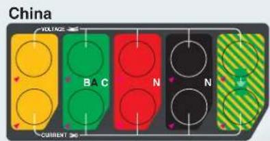
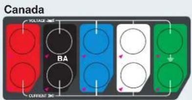
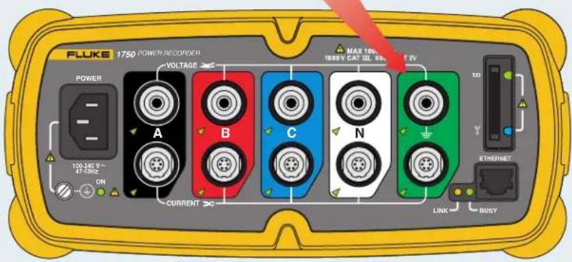
Figure 2. Applying the Front Panel Decal
azd17f.eps
Caution
Connecting the supplemental ground terminal and the line cord safety ground to different ground potentials creates a ground loop that can damage the Recorder.
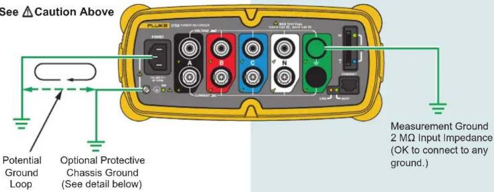
Different Power System
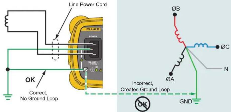
Figure 3. Connecting the Supplemental Ground Terminal
azd11f.eps
Charging the PDA Battery
Your PDA is shipped with a discharged or partially charged, rechargeable battery. You should fully charge the battery before setting up the device, and recharge it regularly. Refer to your PDA user's guide for detailed information about the battery.
Caution
Do not leave important data on the PDA. If the battery discharges completely, you will lose all data not stored in File Store (ROM). Discharging the battery completely is similar to performing a hard reset. Refer to the PDA Users Manual for more information.
Installing the Software
This section describes how to install Fluke Power View software on the PDA and Fluke Power Analyze software on your PC. Keep your product CD in case you need to reinstall this software in the future. You should periodically check the Fluke website: www.fluke.com to see if any 1750 firmware or application software updates are available for download. Fluke encourages you to register the Recorder. After your Recorder has been registered, you will receive email notifications of firmware and software update availability.
Installing Power View on the PDA
- Insert the CD that ships with your PDA. Follow the on-screen instructions to install the ActiveSync software for Windows XP (or Mobile Device Center for Windows Vista and Windows 7) that allows your PC to communicate with the PDA.
- Connect the PDA to your PC with the USB lead and establish communication between the PDA and your PC. Keep your product CD in case you need to reinstall this software in the future.
- Insert the CD that ships with your Recorder in the CD-ROM drive on your PC.
- A window appears that lists options on the CD. If the install software window does not automatically appear, do the following:
a. Use Windows Explorer to locate the sw/FPV_Vx.yy.exe file on the CD. Replace x.yy with the current version number shipped on the CD.
b. Double-click FPV_Vx.yy_Install.exe to launch the installation program.
- Select a language preference for the installation.
- Follow the on-screen prompts.
Power View is installed in the Programs folder on the PDA.
- To start Power View, select Start, and then Programs on the PDA.
- Tap the Power View icon ( ) to start using the application.
Language Selection
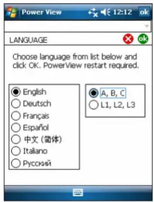
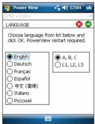
Power View features a localized user interface for English, German, French, Spanish, Chinese, and Italian. When Power View operates for the first time on a new PDA or after a hard reset, it directly opens the language setup window. This window is also accessed by Menu>1750 Setup>Language.
The Language window also provides the option to choose between the phase identifiers A, B, C and L1, L2, L3.
azd110.bmp
PC System Requirement for Power Analyze
- Windows XP, Windows Vista 32/64bit, Windows 7 32/64bit. Administrator privileges are required to install applications.
• PC with 500 MHz or faster processor. - 256 MB RAM, 1 GB recommended (100 MB of available disk space, 10 GB recommended).
- 1024 x 768 or higher resolution video.
- Keyboard and mouse.
Installing Power Analyze
Before installing the software on your PC, make sure you have Internet Explorer version 6, or later, installed. Other recommended software:
- Adobe Acrobat Reader
• Microsoft Word 2000 or higher
• Microsoft Excel 2000 or higher
Caution
Do not remove the CD until after you have successfully installed the software, rebooted the machine, and opened the application.
-
Insert the CD into your CD-ROM drive.
-
A window appears that lists options on the CD. If the window does not automatically appear:
a. Use Windows Explorer to locate the sw/FPA_Vx.yy.exe file on the CD. Replace x.yy with the current version number shipped on the CD.
b. Double-click FPA_Vx.yy_Install.exe.
-
Select a language preference for the installation process. Power Analyze initially starts in this language. You can change the language from the menu Settings>Language.
-
Follow the installation instructions that appear. After software installation is
complete, the Power Analyze icon 📋 appears on your desktop.
- Start Power Analyze on your PC by choosing Start >All Programs >Fluke >Power
Analyze >Power Analyze or double-click the Power Analyze icon 📋 on your desktop.
- After the installation is complete, please take a few minutes to complete your product registration. You can register quickly online (preferred) at http://register.fluke.com or you can print the form and fax it to the number provided on the form. Product registration is very important since it allows you to get free software updates and helps us provide you with the fastest and most efficient technical support.
Note
You may need to change your Windows firewall settings to allow the program FPA.exe to use ports 18571 (TCP) and 18572 (UDP). For more on changing firewall settings, refer to http://support.microsoft.com.
Installing the Power Recorder at a Facility
This section describes the steps you need to take to set up the Recorder at a facility and begin a recording session.
Work Flow
There are three distinct stages for a recording session.
- Setup
Setup, hookup, and verification of connections and measured signals. This is when you will want to clear the Recorder memory (not required, but best practice because data download when finished only contains your new data). This is a good time to change any recorder settings. Edit the measurement description now or after downloading the measurement data and insert annotations and/or an optional START mark into the recorded data stream. Annotations are messages or notes you insert into the data stream during a recording session.
• Interim checkup, mid-recording session
At this time, you may want to re-check all the live input signals, and download the data recorded since the beginning of the recording session. This does not interfere with ongoing recording in any way. Annotation capability is always available during the recording session.
• End of recording session
You can re-verify if desired, correctness of live data and then download data, power off the Recorder, and pack up for transport.
Installing the Recorder
- Position the Recorder within 2 m (6 ft) of the monitoring location.
- The Recorder can be set on the floor or a table, or attached and secured to a pole or other mounting surface. The Recorder can be oriented vertically or horizontally.
- Connect the Recorder to a 100 to 240 V ac power source, 50 or 60 Hz.
- Plug the power cord into a properly-grounded wall outlet.
Caution
To avoid damage to the Recorder:
- Ground the chassis as appropriate according to your power connection before you do anything else.
- Connect the power cord to the Recorder using the appropriate supplied adapter.
- Connect the power cord to a properly grounded wall outlet.
- Be sure to plug the power cord into the Recorder panel BEFORE connecting it to an outlet.
After a minute, or two, all LEDs should flash ON, then OFF, and then each should turn ON and OFF in sequence. The LEDs will then remain on if you make secure test lead connections and there is sufficient voltage and current.
- Turn on the PDA and tap the Power View icon to launch Power View.
If a Recorder is within range and is not password protected, it should appear in the drop down menu just below the main title bar on the PDA. You may need to select Browse for recorder when first connecting. Select the recorder you want to browse to with the PDA stylus. Upon selection, the Home screen for live data appears.
If more than one Recorder is within range, these will appear in the drop down menu list.
- If you have previously established password protection for the Recorder, you must type the correct password in the Password text box and click OK. (Password protection is established for a specific Recorder using either the Setup Password menu in Power View or the Power Analyze software).
Connecting the Recorder to the Wiring
After you have set up the Recorder you are ready to connect the voltage leads and current probe or flexi-probes to the power network being tested. Refer to the Power Type diagrams provided on the PDA or in this manual.
⚠ Warning
To prevent possible electrical shock, Flexi-probes should not be applied or removed from hazardous live conductors.
In most cases, you should install the current probes first. Because they are clamped around wires, current probes are usually more secure than voltage probes. Examine the conductors you are about to connect to and determine if you should attach the current probes to the phase wires or busbars before you connect the voltage probes.
- Select and attach the appropriate current probes to the Recorder.
- Select and attach the appropriate voltage test leads and probes to the Recorder.
Note
If your power connections require potential transformers (PTs) or current transformers (CTs), you can use the ratio settings in Power View to set the Recorder to display readings as they exist on the primary side of the PT and CT (for example, 12000 V).
-
Connect the Recorder to the wiring by first connecting the measurement ground test lead to the distribution system ground, and then the neutral probe to neutral.
-
Connect the ground current probe to the distribution system ground and the neutral current probe to neutral, with the arrow on the current probe pointing towards the load (away from the source) in each case.
-
Connect the remaining current probes to the power network.
• The arrow on the current probe should point toward the load.
- Use the color-coding on the leads to help you connect the probes to the correct phases, neutral and ground.
- Connect the remaining voltage probes.
Note
Make sure the voltage probes and current probes are paired correctly, Phase A (L1) voltage to Phase A (L1) current and so forth. Calculations are made in pairs and cannot be changed after data is recorded. The leads for the voltage probe and current probe of the same color should be attached to the same phase wire or busbar.
-
Check the LED for each phase to make sure a connection is established.
-
When a phase LED is ON or lighted, you know that the connection is active and that voltage and current is within the normal range.
- When a phase LED is BLINKING, you are connected but the voltage or current is exceeding the normal range or exceeding the range of the probe that you are using.
- When a current LED is OFF or unlit, there is insufficient current present in the line.
Verifying Your Connection
Before you leave the Recorder to accumulate data at the facility, double-check the connections.
- Make sure the current probes are secured and completely closed around the conductors and that the voltage and current LEDs are steady-on.
- Use the PHASOR screen on the PDA or PC to verify that the voltage and current connections are correct. You can swap the connections using Power View if they are incorrect.
Finishing Up
After making any corrections to the connections, recheck the PHASOR diagrams to confirm your connection. Make sure the nominal voltage, nominal line frequency, and power type (delta, wye, other) are correct before you leave the Recorder. It is a good practice to insert a Start Mark when you are finished with all settings so you can download data and ignore useless readings and events common at the beginning probe connecting activities. You can also use the “Erase Memory” function and measurement
descriptions such as company, name, and measurement purpose. This can be done at this point or after downloading the measurement data.
Managing Recorded Data
Recorded data resides in the Recorder on an internal non-physically accessible flash memory circuit. The transfer of recorded data to the SD card in the Recorder's SD slot is automatic when you insert the SD card or you request a download action using the PDA. Downloading to a PC running Fluke Power Analyze Software (included) using the Ethernet cable is recommended and the fastest way to retrieve data from the Recorder.
Note
To stop the automatic copy from the SD card memory, go to Menu >Tools >1750 Internal Memory or Menu >Tools >1750 SD Memory.
It is never technically necessary to erase internal memory. When the Recorder has new data to record, it does so automatically, overwriting the oldest data (circular memory). You can erase internal memory for security reasons, or if you want to simplify what you will be seeing in the download data screen. The start and end times will represent one recording session when old data is erased.
Note
Data is not removed from internal Recorder memory until you erase it using Power View software on the PDA or Power Analyze software on your PC.
Power Type Diagrams
The wiring illustrations included cover the standard power configurations that are selectable in Power View or Power Analyze software. The diagrams are provided as an aid in making the correct test lead connections. Power type diagrams are also included on your PDA and can be referenced when you are setting up nominal power on the Recorder.
Available power type settings are:
• One-Phase Plus Neutral (Figure 4)
• One-Phase IT No Neutral (Figure 5)
• One-Phase-Split Phase (Figure 6)
• Three-Phase Wye (Figure 7)
• Three-Phase Delta (Figure 8)
• Three-Phase IT (Figure 9)
• Three-Phase High Leg (Figure 10)
• Three-Phase Open Leg (Figure 11)
• 2-Element Delta (Figure 12)
- 2 12 -Element Wye (Figure 13)
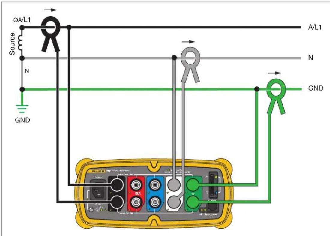
Example: Branch circuit at an outlet.
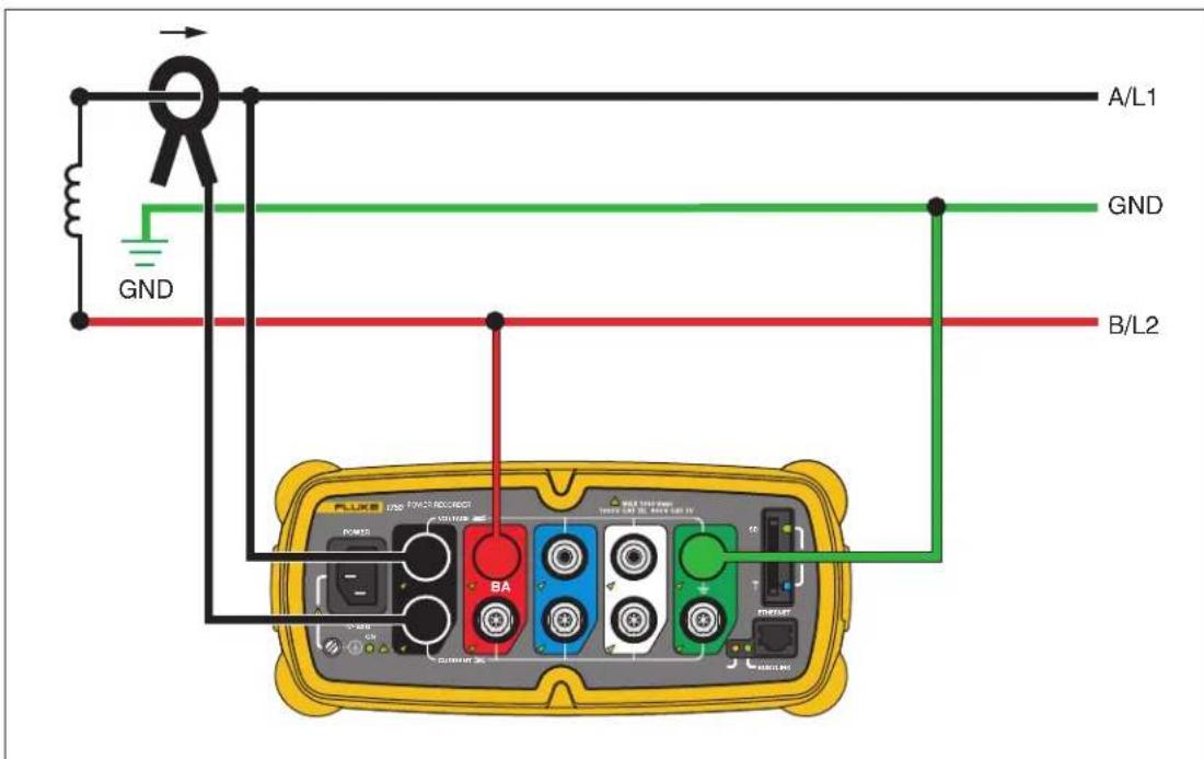
Figure 5. One-Phase IT No Neutral
azd14f.eps
Example: Used in Norway and in some hospitals. This would be the connection at a branch circuit.
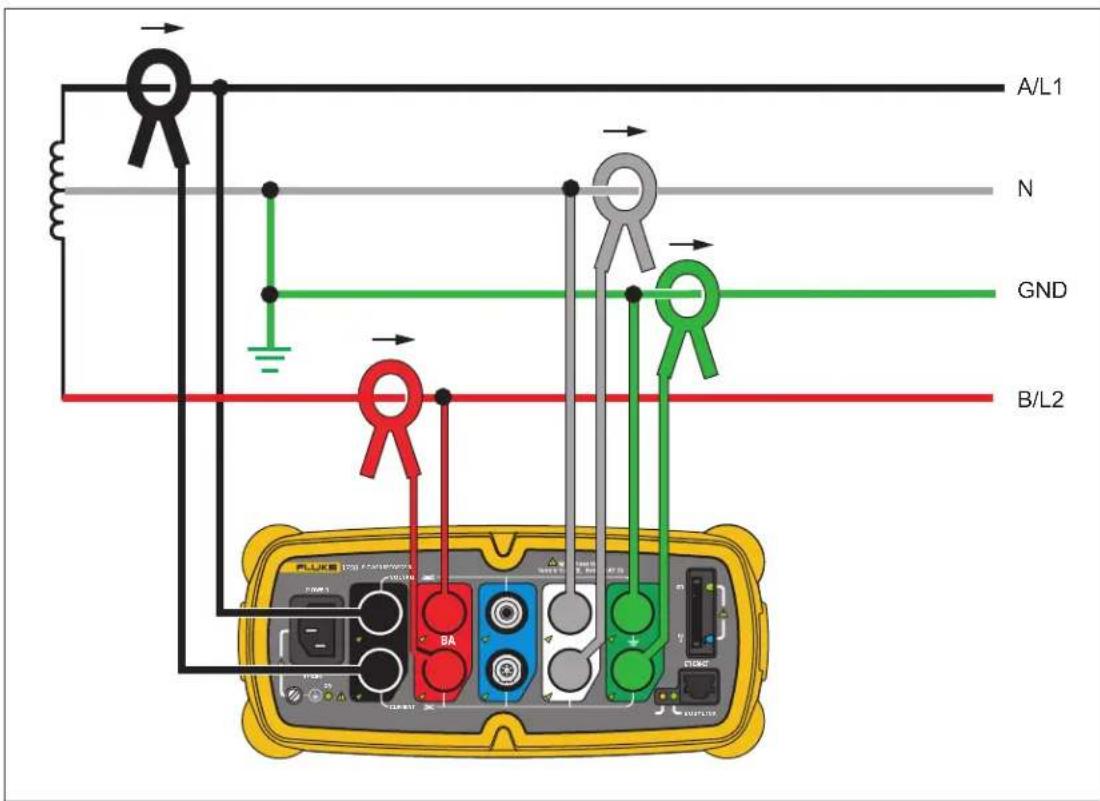
Figure 6. One-Phase Split Phase
azd03f.eps
Example: A North American residential installation at the service entrance.
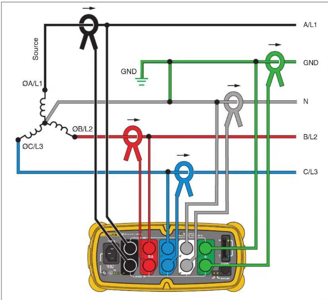
Figure 7. Three-Phase Wye
azd04f.eps
Example: Also called “Star” or four-wire connection. Typical commercial building power.
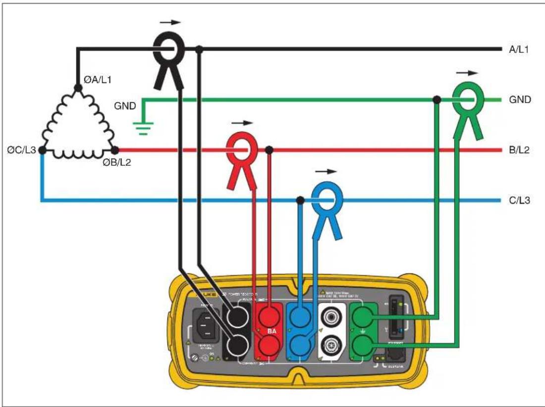
Figure 8. Three-Phase Delta
azd05f.eps
Example: Often found in industrial settings where electric motors are used.
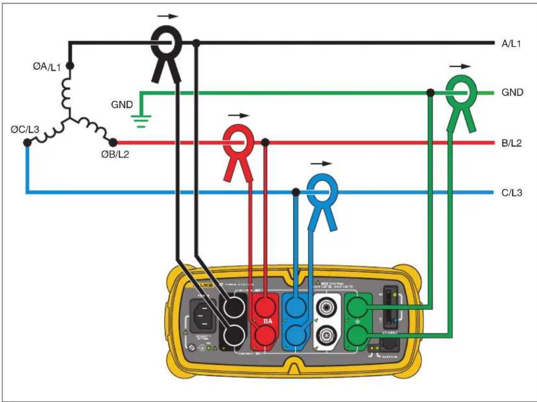
Figure 9. Three-Phase IT
azd12f.eps
Example: Industrial power in countries that use the IT (Isolated Terra) system, such as Norway.
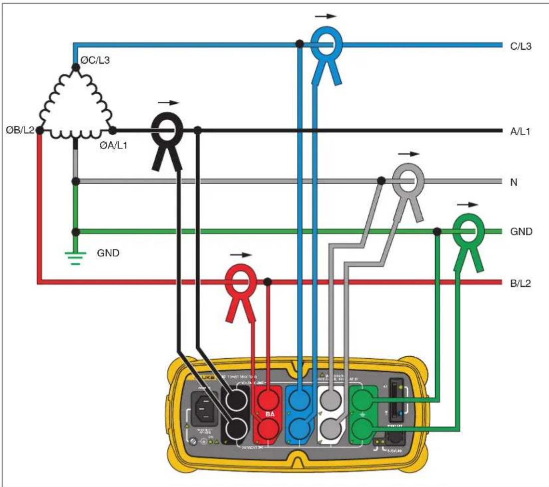
Figure 10. Three-Phase High Leg
azd08f.eps
Example: A way to get a 120V single phase feed by tapping across part of a leg in a delta power system
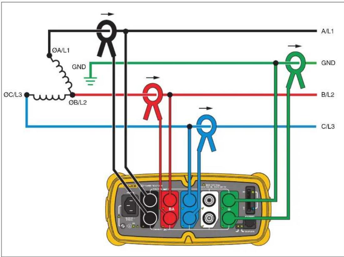
Figure 11. Three-Phase Open Leg
azd18f.eps
Example: A variant of power transformer winding type.
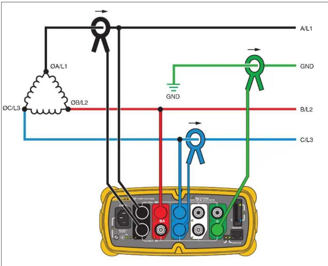
Example: Blondel or Aron connection, used to measure power like a two-element revenue power meter.
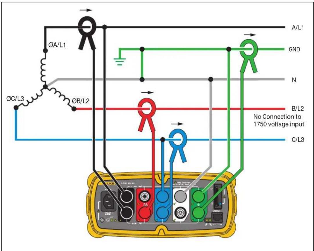
Figure 13. 2 12 -Element Wye
azd07f.eps
Example: Blondel or Aron system for 4-wire (Wye) power secondaries.
Communicating with the Recorder Using Power View
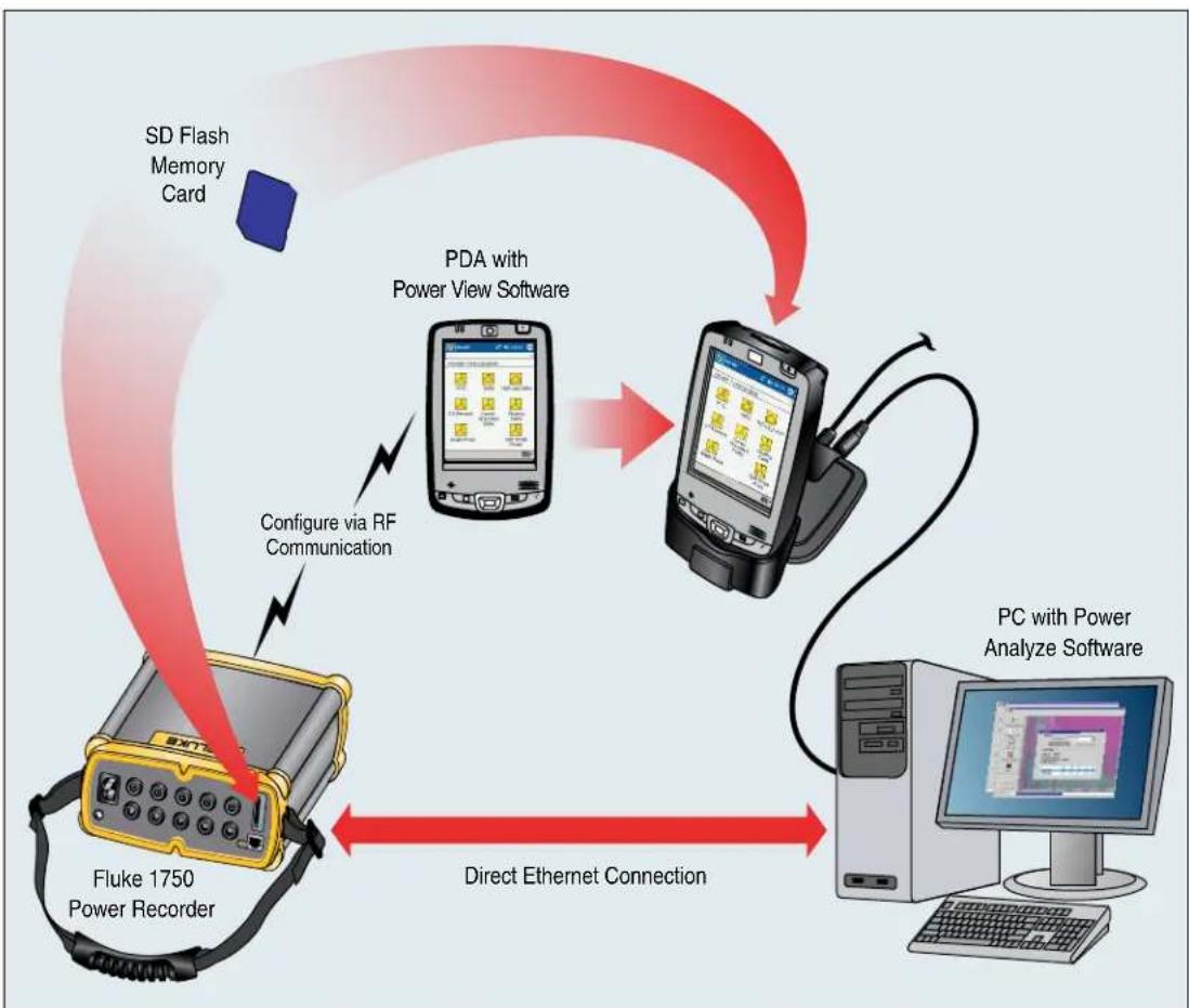
The PDA serves as your control panel for the Recorder. The Power View software installed on the PDA is designed to function as a remote front panel for the Recorder, since the Recorder itself is a “black box” with no integral display or external controls other than status LEDs. With Power View installed on the PDA, you are relieved of the burden of having to carry a laptop and Ethernet cable to a remote site when setting up the Recorder, checking its progress, or finishing a monitoring session.
You can alternatively connect to a Recorder from a PC directly using an Ethernet cable or remotely over an IP network. You can then use Fluke Power Analyze to set up the Recorder, view power measurements wherever the Recorder is installed, or download data from the Recorder.
Power View communicates with the PDA using a wireless controller radio interface. There is no provision for a hardwired PDA interface to the Ethernet port on the Recorder. After data is recorded and downloaded to a PC, you can analyze the recorded data using the Power Analyze software.
flowchart
graph TD
    A["Fluke 1750 Power Recorder"] -->|Configure via RF Communication| B["PDA with Power View Software"]
    B --> C["PC with Power Analyze Software"]
    C --> D["Computer"]
    E["SD Flash Memory Card"] --> A
    F["Direct Ethernet Connection"] --> C
Figure 14. Connecting to the Recorder
azd01f.emf
Navigating in Power View on the PDA
The Menu Bar on the bottom of the Power View screen allows you to quickly and easily configure a Recorder, view live data, and transfer data to the Secure Data (SD) card for viewing and analysis on your desktop computer using the companion Power Analyze software.
Power View Menus
Live
Brings up a list of the live detail views: Scope, Meter, Phasor, Harmonics, and Trend. There are configurable detail views of each type of screen available by tapping the sector of interest or the Live menu. Once a detail view is selected, navigation to all available detail views is accomplished using the Live menu.
Menu > Tools opens the Data Memory Management screens and the Shut Down command to turn off the Recorder. Data Memory Management has screens for downloading to the SD card inserted in the Recorder, erasing the Recorder's internal memory, and erasing the SD card files.
Menu > 1750 Setup brings up the setup screen that allows you to configure the Recorder and set recording period information. Using this function, you can tap the appropriate icon to set the following:
- Clock
- Probe Detect
- IP Address
• Measurement Description - Nominal Power
- Phase Swap
- Volts/Current Ratio
- Recorder Name/Password
- Snapshot Period
- Language
Icons on the Menu Bar
and are used to toggle between voltage and current wave forms. Tap either V or A and then Live>Home to see each parameter's detailed data. The PHASOR screen always shows both V & A (volts and amps). is replaced with on the detail views, as voltage and current data can be viewed simultaneously.
In all the detail live view screens, a line selection menu is available using the button at the bottom. This is a checkbox that is used to select the voltage and current channels you want to display.
[NO TEXT]
The Snapshot icon triggers the Recorder to capture high-resolution waveform data and save it in the recorded data stream. This waveform capture is identical to the snapshots taken automatically when you set the “snapshot period” in the 1750 Setup menu.
[Non-Text]
This icon brings up the Annotate screen. Use the annotate menu to enter text or to insert a file name and load it into the recorded data stream in the Recorder. Annotations can be used to make notes, or to insert a file name of an image or audio file. You can enter multiple start and stop annotations. START and stop annotations are not paired and are not restricted to being used as literally “start” and “stop”. Annotations are often done at the start of a power recording session.
Menu Tree
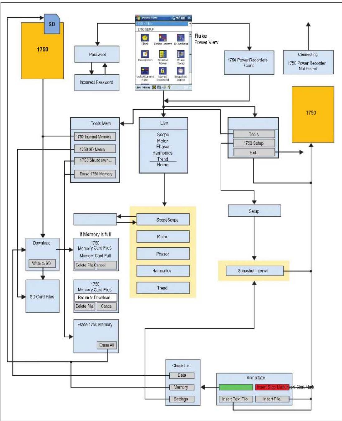
The following figure provides an overview of the Power View menu structure that will be helpful in navigating through the Power View application.
flowchart
graph TD
    A["SD"] --> B["Password"]
    B --> C["Incorrect Password"]
    C --> D["Tools Menu"]
    D --> E["1750 Internal Memory"]
    D --> F["1750 SD Memo"]
    D --> G["1750 Shutdown..."]
    D --> H["Erase 1750 Memory"]
    I["Power View"] --> J["Fluke Power View"]
    J --> K["1750 Power Recorders Found"]
    K --> L["Connecting 1750 Power Recorder Not Found"]
    M["Download"] --> N["Write to SD"]
    N --> O["SD Card Files"]
    O --> P["Adder"]
    Q["Tools"] --> R["ScopeScope"]
    S["Setup"] --> T["Meter"]
    U["Snapshot Interval"] --> V["Trend"]
    W["Check List"] --> X["Data"]
    W --> Y["Memory"]
    W --> Z["Settings"]
    AA["Annotate"] --> AB["Insert Stop Mark"]
    AB --> AC["Insert Text File"]
    AB --> AD["Insert File"]
    AE["1750"] --> AF["Live"]
    AF --> AG["Scope Meter Phasor Harmonics Trend Home"]
    AG --> AH["Tools Setup Exit"]
    AH --> AI["Setup"]
    AI --> AJ["Snapshot Interval"]
    AJ --> AK["Adder"]
    AL["1750"] --> AM["Software Icon"]
    AM --> AN["Update Detect IP Address"]
    AN --> AO["Description Nominal Power Phase Swap"]
    AO --> AP["Volt/Current Ratio Name/Password Snapshot Period"]
    AP --> AQ["Live Menu"]
Figure 15. Power View Menu Tree
azd15f.eps
Home Screen
The Home screen is the top-level screen, accessed when you start Power View or when you tap Live and then Home on the Menu Bar.
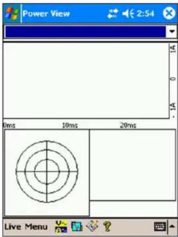
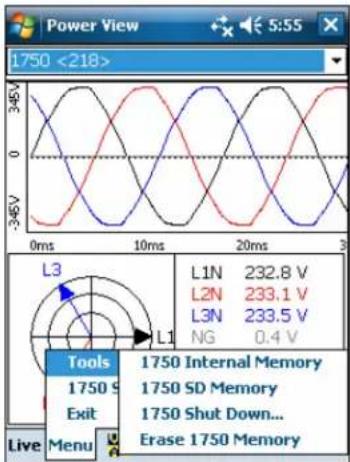
The Home screen contains a 1.5 cycle waveform screen, a digital meter screen, and a PHASOR screen. The parameters shown in this screen are not configurable. All phases are shown simultaneously, either all voltage or all current.
If no Recorders are within range, the following screen appears:
azd111.bmp
azd112.bmp
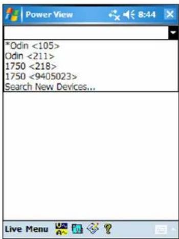
If more than one Recorder is within range, the Recorder selection screen appears. An asterisk preceding the Recorder name means that unit is password protected. If your recorder is not listed, but in range, press "Search New Devices" to update the list.
azd113.bmp
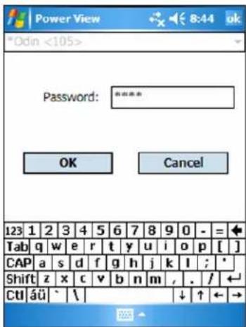
If the selected Recorder is not password protected, the Home screen appears. If password protection is set, the Password screen appears instead.
azd114.bmp
If the password is incorrect the password text field is cleared and then you can re-enter the password. When the password is accepted, the Home screen appears.
Note
A screen to set up password protection for a Recorder is provided in the 1750 Setup menu.
Downloading Data and Erasing Memory
Use the Data menu options to manage the Recorder memory and download recorded data to the SD card plugged into the Recorder's (not the PDA) SD card slot. You are downloading recorded data from the flash memory to an SD card in the Recorder. You can later copy the data to your PC for review using the Power Analyze software.
Auto Download
The Auto Download feature copies all recorded data to the SD card without a PDA or PC. Auto Download starts when you insert the SD card and have no connection to Power View or Power Analyze. The SD card status indicator flashes while a copy of the data moves to the SD Memory card.
Note
Do not remove the SD card while the SD status indicator is flashing. It may result in corrupted data integrity of the SD card. The SD card can be safely removed when the SD status indicator is off.
The automatic download can be aborted with Power View by either tabbing on Menu>Tools>1750 Internal Memory or Menu>Tools>1750 SD Memory.
If the download does not start automatically:
- Verify that neither Power View nor Power Analyze is connected to the device.
- Watch the SD status indicator. As soon as an SD card is inserted, the indicator flashes green for a short time. This is the indication that the device has recognized the SD card. If nothing happens the SD card is not compatible with the Fluke 1750.
- Check if the SD card is write-protected. Make sure the slider on the card is not in the LOCK position.
If the SD status indicator flashes when the SD card has been inserted but it does not flash for a longer period of time (>1 second) the available space might be insufficient. Use a new card without any files or delete files on the SD card with the use of the PDA or a card reader.
PDA Download
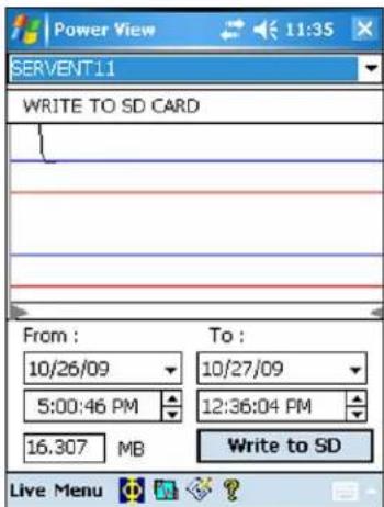
Tap 1750 Internal Memory in the Data menu to view the Download screen.
azd116.bmp
The Download screen shows a three-phase rms V strip chart with date and timescale shown. This represents the data in the Recorder internal memory. The default settings of the start and stop times is everything in memory. To download ALL, tap the Write to SD button. If you want to trim off data that contains partial information because probes were being connected, select the START mark annotation (if one was entered by the user) as The gray cursor lines right and left with triangular arrowheads at the bottom of the screen show the start and stop times currently selected for download. Green and red flags are START and STOP mark annotations inserted during the recording session. Yellow flags are file name annotations inserted during the recording session, or setup parameter changes that change the data significantly, such as nominal voltage or power type.
azd117.bmp
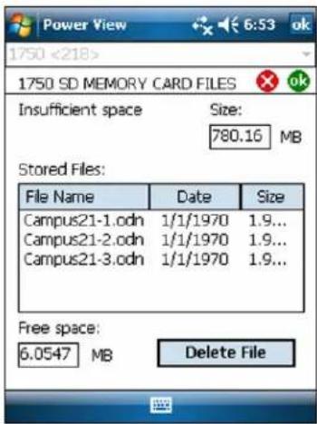
If the SD storage card already contains data files, it may not have room for the new download. Power View alerts you to this condition and asks if you would like to erase the SD card before downloading.
azd107s.bmp
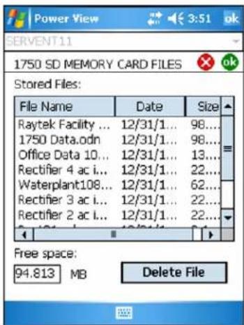
You can also access the SD card to delete files by selecting Menu>Tools>1750 SD Memory.
You can delete files as necessary, and when satisfied that there is room on the card, proceed to write the selected internal Recorder memory data to the SD card.
azd108s.bmp
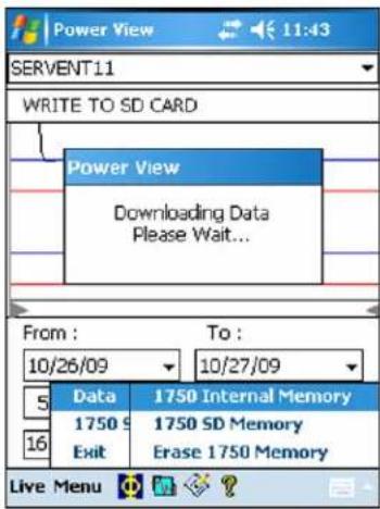
When there is room on the card, a message confirming the download will appear.
azd118.bmp
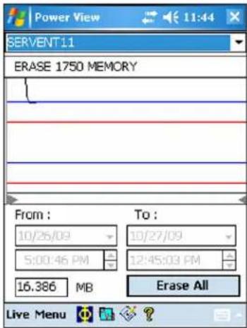
You can also tap the Erase 1750 Memory from the Data menu option which is available under Menu, and tap the Erase All button to erase all power quality data stored in the Recorder. Even then, if you want, you can leave old data in Recorder memory. It will be overwritten automatically when you start your next Recorder session, so it never has an adverse effect on recorded data quality or quantity.
azd109s.bmp
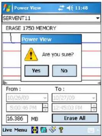
When you choose to Erase All, the following popup caution "Are you sure?" appears on the screen.
azd119.bmp
Note
You can also download data by connecting your PC directly to the Recorder with an Ethernet cable and run Power Analyze in the 1750 Live mode. All of the functions (controller, PDA, and Power View) are duplicated in 1750 Live mode.
Viewing Live Data
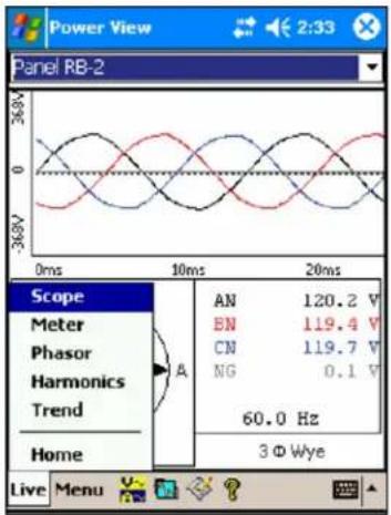
The Live menu is used to view live data on the circuits on the circuits for example, Scope, Meter, Phasor, or Harmonics.
azd120.bmp
Scope Screen
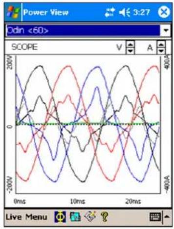
The Scope screen shows 1.5 cycle waveform data for the volts and amp lines selected in the check boxes on Phase View screen. Tap the Phase icon ( ) to display the Phase View screen.
azd121.bmp
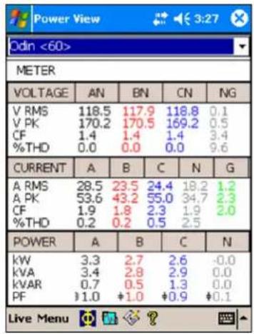
Meter Screen
The Meter screen shows numeric readings for all selected phases.
azd122.bmp
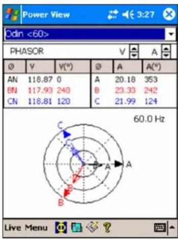
Phasor Screen
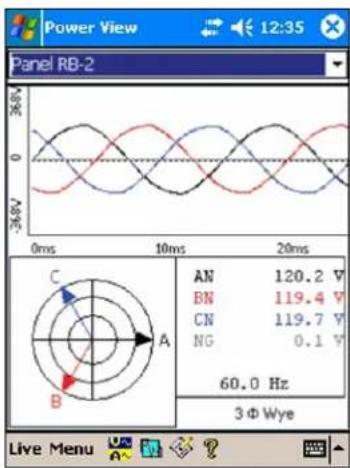
The Phasor screen shows voltage (long arrows with solid arrowheads), current amplitudes, and phase angles. This screen is used to verify proper test lead and current probe connections. You can use the V and A arrows on the upper right of the screen to change the scaling of voltage and current on the PHASOR diagram.
You can easily correct an erroneous Recorder connection by going directly to Menu\1750 Setup\Phase Swap (☑) and using the Recorder to internally invert a CT, swap a voltage or CT phase, or modify a scaling parameter, then return to the screen to verify that the correction has been made. There is no need to touch the cables. See “Phase Swap” later in the manual for additional information.
radar
| Point | Value | |---|---| | A | 20.18 | | B | 23.33 | | C | 21.99 | | D | 353 | | E | 242 | | F | 117.93 | | G | 118.81 | | H | 120 | The chart displays a radar or polar coordinate system with concentric circles representing radial distances from the center of the circle. The text '60.0 Hz' is displayed in the bottom-right corner.azd123.bmp
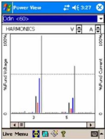
Harmonics Screen
The Harmonics screen shows the magnitudes of the selected phases of V and I. The scale is % of nominal.
The slider control displays harmonics of a higher order up to the 50^th . The V and A scaling arrows are on the screen in the upper right.
If the power type is delta, V phases are AB, BC, and CA (L1L2, L2L3, L3L1 is available as a localized European labeling scheme). If the power type is Wye, V phases are AN, BN, CN, and NG. (N = neutral, G = ground).
bar
Power View Odin <60> HARMONICS V A 100% %Fund Voltage 100% %Fund Current 0 Live Menu124.bmp azd
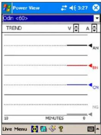
Trend Screen
The Trend screen shows live data being recorded as a strip chart display of the selected phases of voltage or current. This moment in time is visible on the right side of the graph.
The traces fill the screen in 10 minutes, and continue FIFO (first-in, first-out). This feature is intended to paint a picture of the short-term stability of the power system. The V and A scaling arrows on the upper right work like the scaling arrows on the PHASOR screen.
azd125.bmp
Viewing Phases
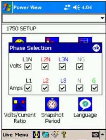
In all the detail Live View screen, a line selection menu is available using the button at the bottom. The Phase Selection screen reveals check boxes for selecting the voltage and current channels you want to display.
azd126.bmp
Setting Up the Recorder
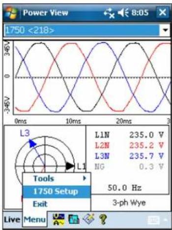
To adjust the settings of the Recorder, tap Menu>1750 Setup.
azd127.bmp
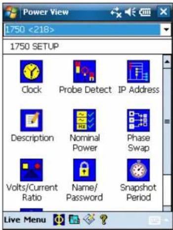
The Setup screen shows setup options.
azd140.bmp
From the Setup screen, you can adjust either the recording period information or the Recorder settings. Tap an icon on the Setup screen to view or configure:
- Clock
- Probe Detect
- IP Address
• Measurement Description - Nominal Power
- Phase Swap
- Volts/Current Ratio
- Recorder Name/Password
- Snapshot Period
- Language
Setting the Clock
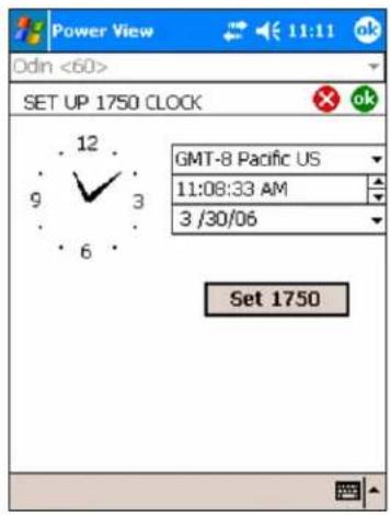
Use this feature to set the PDA clock or clock to synchronize the Recorder with the PDA clock.
azd128.bpm
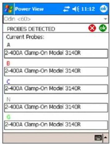
Probe Detect
This screen shows the types of probes attached to the Recorder current inputs. Current probes are automatically detected.
azd129.bmp
Setting the IP Address
Select Obtain Address Automatically unless your company's IT department has specific requirements that require assigned IP addresses. When this mode is active, the assigned IP Address and Subnet Mask show in gray. The Default Gateway address is not supported and this field always defaults to 0.0.0.0.
![SET UP NETWORK Obtain Address Automatically Use this Address IP Address 129 . 168 . 214 . 243 Subnet Mask 255 . 255 . 254 . 0 Default Gateway 129 . 196 . 214 . 1 123 1 2 3 4 5 6 7 8 9 0 - = Tab q w e r t y u i o p [ ] CAP a s d f g h j k l ; * Shift z x c v b n m , . / Ctú áü ` \ ↓ ↑ ← →](/content/2026/05/977527/images/1869247f2181008494808257b043daa8f7b1c6925111b142ada263c0dd23cc1f.jpg)
azd130.bmp
Adding a Measurement Description
Click on the arrow and select one of the six available captions from the list box and enter the text in the text field below. The number of characters is limited to 50. Click on Insert to apply the changes.
You may change or delete the caption. The maximum possible length for caption text is 20 characters.
To apply changes, click on Apply.
Click OK to close the window and send the measurement description to the device.
![Power View 1750 <218> Measurement Description Company: Apply Fluke Insert Cancel 123 1 2 3 4 5 6 7 8 9 0 - = + Tab q w e r t y u i o p [ ] CAP a s d f g h j k l ; * Shift z x c v b n m , . / ← Ctrl äü ` \ ↓ ↑ ← →](/content/2026/05/977527/images/034bac503ecfd1a92f46bb05e80ffbab18a8d1e6b6c96e204e7320865d950ac7.jpg)
azd141.bmp
Configure Nominal Power Values
This window contains the setup for Power Config, Nominal Voltage, and Frequency. It is important to correctly configure these values before the measurement as some calculations are based on these settings and cannot be recalculated after the measurement has been performed. Click on the 3-phase delta icon to display the wiring diagram of the selected topology. The list box of nominal voltage levels contains commonly used voltage levels. Different voltage levels may be entered if required.
![Power View SET UP NOMINAL V/ F/TYPE Power Config 3-ph Wye Nominal V 120 V RMS Frequency 60 Hz 123 1 2 3 4 5 6 7 8 9 0 - = Tab q w e r t y u i o p [ ] CAP a s d f g h j k l ; * Shift z x c v b n m , . / ← Ctl äü ' \ ↓ ↑ ← →](/content/2026/05/977527/images/b7f1fa785c827581e499b28cd9de33dc30450dc351f536ad23dfbd74d0f00283.jpg)
azd131.bmp
Using Phase Swap
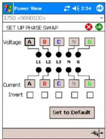
Rather than having to change the physical connections to the power system, use the Phase Swap feature to make a software-selectable correction without physically switching the cable. You can select from the following:
- Swap any voltage input
- Swap any current input
- Invert any current input clamp
The screen shows check boxes to invert any current probe. Current probes are directional, and selecting “invert” has the effect of removing the probe and turning it around.
If the power type is delta, V phases are AB, BC, and CA (L1L2, L2L3, L3L1 is available as an optional setting). If the power type is Wye, V phases are AN, BN, CN, and NG. (N = neutral, G = ground).
flowchart
graph TD
    A["A"] --> L1["L1"]
    B["B"] --> L2["L2"]
    C["C"] --> L3["L3"]
    N["N"] --> L4["N"]
    G["G"] --> L5["G"]
    L1 --> Current["Current"]
    L2 --> Current
    L3 --> Current
    L4 --> Current
    L5 --> Current
    L6["L1"] --> Invert["Invert"]
    L7["L2"] --> Invert
    L8["L3"] --> Invert
    L9["N"] --> Invert
    L10["G"] --> Invert
    L11["L1"] --> Invert
    L12["L2"] --> Invert
    L13["L3"] --> Invert
    L14["N"] --> Invert
    L15["G"] --> Invert
    L16["L1"] --> Invert
    L17["L2"] --> Invert
    L18["L3"] --> Invert
    L19["N"] --> Invert
    L20["G"] --> Invert
azd133.bmp
Setting the Volts and Current Ratio
Use this menu to add a ratio factor to the voltage or current input on each phase.
Changing the first “1” in each case if there is a potential transformer in series with the voltage connection such as when you want to monitor a medium-voltage network using PTs and CTs to scale the voltage and current to a convenient level for measuring instruments.
The current ratio applies a ratio to the current input in order to show the current present on a medium-voltage network. This feature is intended to be used for sensing low levels of current to represent the much higher levels on the primary side at a substation or step-down transformer that has built-in metering current transformers.
![Power View 11:14 ok Odn <60> SET UP V/A RATIOS Voltage: AN 1 : 1 A 1 : 1 BN 1 : 1 B 1 : 1 CN 1 : 1 C 1 : 1 NG 1 : 1 N 1 : 1 G 1 : 1 G 1 : 1 Current: 123 1 2 3 4 5 6 7 8 9 0 - = ◀ Tab q w e r t y u i o p [ ] CAP a s d f g h j k l ; * Shift z x c v b n m , . / ← Ctl äü ` \ ↓ ↑ ← →](/content/2026/05/977527/images/bc98a67ec9c40150af7ea13846d5586cf941d5f44eea87e4ea433fff4e255f10.jpg)
azd134.bmp
Assign Recorder Name and Password
Use this feature to assign a name identifier to the Recorder and to establish a password for the Recorder. This naming feature is designed to help you keep track of which Recorder is in use. The Recorder name is later associated with the data file that you download from the Recorder.
![Power View 11:13 ok Odin <60> SET UP PASSWORD Enter Instrument Name: Odin <60> Require Password Enter Password: Cancel Re-Enter Password: 123 1 2 3 4 5 6 7 8 9 0 - = + Tab q w e r t y u i o p [ ] CAP a s d f g h j k l ; * Shift z x c v b n m , . / ← Ctrl áü ` \ ↓ ↑ ← →](/content/2026/05/977527/images/3339d8295264069705529527e0e7467544d40cc1ecf7a3860a7ada26e67f2694.jpg)
azd132.bmp
Setting the Snapshot Period - Periodic Waveform Capture Setting
Use the Snapshot Period screen to program the Recorder to take automatic power conditions readings which are then stored in the recorded data stream. These snapshots contain a phasor diagram, waveforms of current and voltage, harmonics profiles, and other data.
- None
- 10 minutes
- 30 minutes
• 1 hour
Note
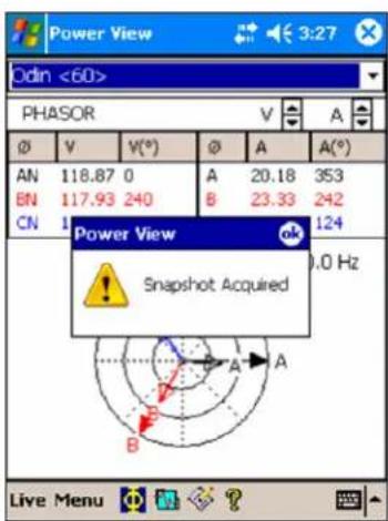
You can take a snapshot manually at any time at any time while connected over the wireless link to a Recorder. Press the Waveform icon 📋 on any of the View screens to take a snapshot. The message, "Snapshot Acquired" confirms that a snapshot was taken.
![Power View 11:15 ok Odn <60> SET UP SNAPSHOT Snapshot Period Selection None 10 Minutes 30 Minutes 1 Hour 123 1 2 3 4 5 6 7 8 9 0 - = ◀ Tab q w e r t y u i o p [ ] CAP a s d f g h j k l ; * Shift z x c v b n m , . / ← Ctú áü ` \ ↓ ↑ ← →](/content/2026/05/977527/images/9e0f183b2e107d29be14ff4502566fb26c89c671fb928f69c1379ac497e3cbf4.jpg)
azd135.bmp
azd139.bmp
Change Display Language and Phase Identifier
Power View features a localized user interface for English, German, French, Spanish, Chinese, and Italian. Select one of these languages and select your preference of phase identifier as A, B, C or L1, L2, L3. A restart of Power View is required to apply these changes.
azd142.bmp
Working with Annotations
Annotations are optional markers that can be inserted by the Recorder operator to flag a particular point in the data when recording. They are usually inserted on using Power View with the wireless PDA.
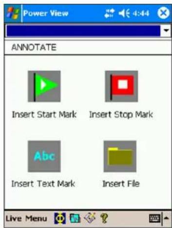
azd137.bmp
There are five types of annotations:
- START annotation (green)
The START annotation can be used to signify where important data begins. For example, the operator might want to establish a start annotation after having finished all probe connections and instrument setup, to indicate that any preceding data was preliminary.
Note
You are not limited to using the START and STOP annotations in pairs, or to show a range of data. You can use each as many times as desired to mark a particular point during recording.
- STOP annotation (red)
The STOP annotation can be used to signify where important data ends. - File annotation (yellow)
File annotations contain the name of a picture or audio file relevant to the data. See “Using Image or Voice Annotations” later in this manual.
- Text annotation
Text annotations contain a text note.
• Power Configuration Change annotation
Power Configuration Change annotations are inserted by the system when a change is made to the Power Configuration in the Recorder. These markers only display in the Download dialog box.
To show or hide annotation markers:
- In the Volts/Amps/Hz or Events view, check or uncheck the Annotations option on the view controls.
To open an annotation:
- In the Volts/Amps/Hz view, Events view, or Download dialog box, click on the annotation.
If the annotation is associated with an audio (.WAV) or image (.jpg) file, the application associated with that file will start and open the file. If the file is not in the default directory \My Documents\Fluke\Power Analyze, a dialog box opens so that you can navigate to the file.
Note
If clicking on an annotation marker does not seem to do anything, the Zoom box is probably selected in the graph toolbar, instead of the Select tool. Click the Select tool and then select the annotation.
To see overlapping annotations:
Sometimes annotations are so close to each other that they actually overlap on the Volts/Amps/Hz reference graph. When this is the case, if you click on overlapping annotations, a menu opens and you can select either Open, to open the annotation now on top, or Select Next Overlapping Annotation, to bring the next one to the top.
- To open the annotation now on top, choose Open.
- To bring the next annotation to the top, choose Select Next Overlapping Annotation. To then open that annotation, click on it again and choose Open.
Note
To see overlapping annotations more clearly on the Volts/Amps/Hz reference graph, move the selection cursors so that they just surround the area that contains the overlapping illustrations. The Detail graph adjusts as the cursors move, zooming in to show the area between the selection cursors. You can now see the annotations separately.
Using Image or Voice Annotations
While you are monitoring data with a Recorder, you may find it helpful to take a picture that relates to the power quality data you are recording, or to record verbal comments as you observe the conditions or review the data being measured. You can then associate the image or recording with the data being recorded by adding annotations that reference them.
The PDA includes a microphone for recording notes which are saved as .WAV files, and an optional camera accessory is available on the PDA which will capture images as .jpg files.
You can associate both images and audio files with the data being gathered in the Recorder by inserting annotations and specifying the name of a .WAV or .jpg file. After you download data from the Recorder, you can then move the image and audio files to the PC along with the recorded data (.odn) file.
Note
You can also associate other types of files with the annotation. For example, if you had a .MPG file with a movie, or a .DOC file with associated information. You can enter any file name using this annotation method.
Inserting Image or Voice Annotations
- Set up the Recorder and begin monitoring.
- Using your PDA-cam (not available in standard PDA supplied) or another camera, take a picture of what you want to capture.
- Click the Annotate icon to display the Annotate screen.
- Move the image or audio file to a location that will make it easier to Transfer it to a PC later, when you download and move the recorded data file to your PC. Place the file into the synchronization folder on your PDA, so that it will be automatically transferred into the sync folder on the PC the next time you dock the PDA.
Turn off the Recorder
The Recorder always has the UPS enabled to allow a 5-minute pass through time on a voltage interruption. When you pack the Recorder for transport, you have the option to shut down the Recorder and disable the UPS before unplugging the power cord.
To turn off the Recorder:
- Select Menu>Tools>1750 Shut down...
- Confirm the warning message.
- Wait until the Power LED is solid green.
The power cord can be safely unplugged.
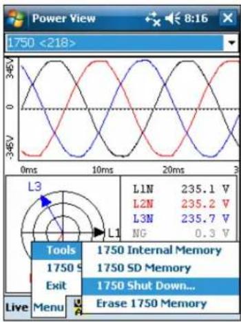
azd143.bmp
Cleaning and Maintenance
The Recorder contains no user serviceable parts. Contact an Authorized Fluke Service Center for repair. Periodically wipe the case with a damp cloth and mild detergent. Do not use abrasives or solvents.
Regulatory Information for Wireless Communication
Caution
- Any changes or modifications to the wireless 2.4 GHz radio not expressly approved by Fluke Corporation could void the user's authority to operate the equipment.
- The distance between the Recorder and the human body must be ≥ 20 cm (7.9 inches) during wireless communication.
- FCC ID: T68FLK1750 or QOQWT 11 (see rear decal on Fluke 1750 for the appropriate ID).
This device complies with Part 15 of the FCC Rules. Operation is subject to the following two conditions: (1) this device may not cause interference, and (2) this device must accept any interference, including interference that may cause undesired operation of the device.
Class A digital device: A digital device that is marketed for use in a commercial, industrial or business environment, exclusive of a device which is marketed for use by the general public or is intended to be used in the home.
Class B digital device: A digital device that is marketed for use in a residential environment notwithstanding use in commercial, business and industrial environments. Examples of such devices include, but are not limited to, personal computers, calculators, and similar electronic devices that are marketed for use by the general public.
The Fluke 1750 Power Recorder (wireless host) has been tested and found to comply with the limits for a Class A digital device, pursuant to Part 15 of the FCC Rules. These limits are designed to provide reasonable protection against harmful interference when the equipment is operated in a commercial environment. This equipment generates, uses,
and can radiate radio frequency energy and, if not installed and used in accordance with the instruction manual, may cause harmful interference to radio communications. Operation of this equipment in a residential area is likely to cause harmful interference in which case the user will be required to correct the interference at his own expense.
In addition, the internal limited modular radio has been tested and found to comply with the limits for a Class B digital device, pursuant to Part 15 of the FCC Rules. These limits are designed to provide reasonable protection against harmful interference in a residential installation. This equipment generates, uses and can radiate radio frequency energy and, if not installed and used in accordance with the instructions, may cause harmful interference to radio communications. However, there is no guarantee that interference will not occur in a particular installation. If this equipment does cause harmful interference to radio or television reception, which can be determined by turning the equipment off and on, the user is encouraged to try to correct the interference by one or more of the following measures:
- Reorient or relocate the receiving antenna.
- Increase the separation between the equipment and receiver.
- Connect the equipment into an outlet on a circuit different from that to which the receiver is connected.
- Consult the dealer or an experienced radio/TV technician for help.
The term “IC:” before the radio certification number only signifies that Industry of Canada technical specifications were met.
Specifications for the System: Recorder and Power Analyze Software
General Specifications
Power Quality Measurement Standards
Conformance..... IEC 61000-2-4:2002 Class 1, IEC 61000-4-30, IEEE519, IEEE1159, IEEE1459, IEC 61557-12:2008, and EN50160
Clock/Calendar...... Leap years, 24-hour clock
Real-time Clock Accuracy.... Not more than ± 1 s/day
Internal Memory Capacity for Data ...... At least 2 GB
Maximum Recording Period ...... At least 31 days
Measurement Time Control ...... Automatic
Maximum Number of Events ....Limited only by the size of the internal memory.
Power Requirements 100 to 240 V rms ± 10 %, 47-63 Hz, 40 W
Operating Time During Interruptions
(internal UPS operation) .... 5 minutes per interruption, 60 minutes total operating time without recharging
Dimensions 215 x 310 x 35 mm (8.5 x 12.2 x 3.5 inch)
Mass (Weight) 6.3 kg (14 lbs)
Input Specifications
| Measurement Types | One Phase Plus Neutral, One Phase IT No Neutral, One Phase Split Phase, Three Phase Wye, Three Phase Delta, Three Phase IT, Three Phase High Leg, Three Phase Open Leg, 2 Element Delta, 212 Element Wye |
| Input Channels | Voltage: 5 channels, AC/DC Current: 5 channels |
| Voltage Channels | Input resistance: 2 MΩ |
| Input capacitance: <20 pF | |
| Current Channels | Self-identifying probes |
| Types available: current clamps, Flexi-CTs | |
| Measuring Method | Simultaneous digital sampling of voltage and current. Digital PLL synchronized sampling, internal frequency reference used during voltage drops. |
Synchronization and Sampling
| PLL-Synchronization Source......The PLL synchronizes to the A-N/L1-N voltage for wye power types, and to the A-B/L1-L2 voltage for delta power types. All listed power types can be characterized as either wye or delta. | |
| PLL Lock Range......42.5 to 69 Hz | |
| Sampling Frequency......Voltage and current: 256 samples/cycle | |
| Inter-harmonics per IEC61000-4-7: 2560 points / 10 cycles (50 Hz), 3072 points/12 cycles (60 Hz) | |
| Transient Voltage: 5 MHz | |
| A/D Resolution......Voltage and current: 24 bits | |
| Transient voltage: 14 bits | |
Voltage and Current Measurements
| Voltage Measurement Range | AC voltage: 1000 V rms ± 10 % Overrange |
| DC voltage: ± 1000 V + 10 % Overrange | |
| Voltage Crest Factor | 3 or less |
| Voltage Input Impedance | 2 MΩ |
| Current Measurement Range | Depends on current probe used |
| Current Crest Factor | 4 or less |
| Current Input Characteristics | 2 V rms = full scale, 1 MΩ Input Impedance for ferro CTs, low impedance for Flexi-CTs |
Voltage and Current Measurement Accuracy
| RMS Voltage | |
| Measurement Type | True rms calculated continuously: every cycle, every 1/2 cycle, and every 10 or 12 cycles at 50 or 60 Hz respectively, as required by IEC 61000-4-30. |
| Measurement Uncertainty | AC: ± 0.2 % reading ± 0.1 % full scale above 50 V rmsDC: ± 0.5 % reading ± 0.2 % full scale above 50 V dcIf the ac component of a dc signal is below 40 V rms, the dc uncertainty specification may have an offset. |
| RMS Current | |
| Measurement Type | True rms calculated continuously: every cycle, every 1/2 cycle, and every 10 or 12 cycles at 50 or 60 Hz respectively, as required by standards |
| Measurement Uncertainty | ± (0.1 % full scale + 0.5 % reading + current sensor accuracy, valid for 5 % to 100 % of current sensor range |
| Current Accuracy | Ferromagnetic Clamps± (0.1 % full scale + 0.2 % reading + current sensor accuracy), valid for 5 % to 100 % of current sensor rangeFlexible Current Probes± (0.1 % full scale + 0.5 % reading + current sensor accuracy), valid for 5 % to 100 % of current sensor range |
Transient Voltage (Impulse)
Measurement Type...... Waveshape sampling, not peak detect
Full Scale.... 8000 V pk
Sample Resolution.... 200 nS
Measurement Uncertainty....± 5 % reading ± 20 V (test parameters: 1000 V dc, 1000 V rms, 100 kHz)
Dip (Sag) and Swell Measurements
Voltage Swell (rms swell)
Measurement Type......True rms (one cycle calculation by overlapping each half cycle) (voltage between lines is measured for 3P3W lines and phase voltage is measured for 3P4W lines)
Displayed Data ...... Amplitude and duration of swell
Measurement Accuracy..... Same as rms voltage
Voltage Dip (RMS sag)
Measurement Type.....True rms (one cycle calculation by overlapping each half cycle) (voltage between lines is measured for 3P3W lines and phase voltage is measured for 3P4W lines)
Displayed Data ...... Amplitude and duration of dip or interruption
Measurement Accuracy..... Same as rms voltage
Voltage Dropout (Interruption)
Measurement Type..... Same as Voltage Dip
Power and PF Measurement
Calculated per IEEE1459 for best performance when distortions exist
Measurement Type....True rms calculated continuously: every cycle, and every 10 or 12 cycles at 50 or 60 Hz respectively, as required by standards
Measurement Accuracy....± 0.2 % reading ± 0.1 % full scale + current sensor accuracy
Frequency
Measurement Range 42.5 to 69 Hz
Measurement Source ....Same as PLL synchronization source
Measurement Accuracy....± 10 mHz (10 to 110 % of range, with sine wave)
Reactive Power
Accuracy....± 0.2% reading ± 0.1 % full scale + current sensor accuracy
Power Factor
Measurement Range -1.000 (leading) to 0.000 to +1.000 (lagging)
Measurement Accuracy....± 1 digit from the calculation of each measured value (± 3 digits for total)
Displacement Power Factor
Measurement Method......Calculated from the phase difference between voltage fundamental and current fundamental
Measurement Range -1.000 (leading) to 0.000 to + 1.000 (lagging)
Measurement Accuracy.... ± 0.5 % reading ± 2 % full scale ± 1 digit
Voltage Unbalance and Phase Sequence
Measurement Method......Positive sequence voltage divided by negative sequence voltage, per IEC 61000-4-30
Harmonic Voltage and Current
Analysis Window...... rectangular
Analysis Order ......1st to 50th order
Measurement Accuracy ....Voltage / Current: 1st to 20th orders: ± 0.5 % reading ± 0.2 % full scale 21st to 50th orders: ± 1 % reading ± 0.3 % full scale (current sensor accuracy must be included for current and power)
Measurement Method..... IEC 61000-4-7:2002
Inter-harmonic Voltage and Current (Intermediate Harmonics)
Analysis Window...... rectangular
Analysis Orders 0.5 to 49.5th order
Measurement Method..... IEC 61000-4-7:2002
Voltage flicker
Measurement Method...... as per IEC 61000-4-15:2003: 10 min (Pst), 2 h (Plt)
External Interface Specifications
LAN Interface
Connector RJ-45
Speed and Type 10/100 Base-T, auto MDIX
Communications Protocol....TCP/IP over Ethernet
Wireless Controller Interface
Connection..... wireless (2.4 GHz radio)
Speed..... up to 700 kbit/second
Communications Protocol......Bluetooth SPP
Environmental and Safety Specifications
Operating Environment....indoors or in covered area outdoors, up to 2000 m altitude
Storage Temperature and Humidity....-20 °C to 50 °C, 80 % rh max, non-condensing
Operating Temperature and Humidity .... 0 °C to 40 °C, 80 % rh max, non-condensing
Altitude....2000 m (6562 feet)
Maximum Rated Working Voltage
Voltage Terminals.... 1100 V rms
Voltage Durability.... 5550 V rms ac for 1 minute, between voltage input terminals, voltage input terminals and current probes, and voltage input terminals and case (50/60 Hz, 1 mA sense current)
Enclosure Protection.... IP30 (per EN 60529)
Standards Conformance
EMC.... IEC 61326-1:2006 Class A
IEC 61000-3-2:2005, 3^rd Edition
IEC 61000-3-3:2005, 1.2 Edition
AS/NZS 4268:2008 (BT module only)
ETSI EN300328 (V1.7.1:2006)
Safety..... IEC 61010-1:2001
Overvoltage Category 1000 V CAT III, 600 V CAT IV
EN/IEC 61010-032:2002
Pollution Degree 2
- Table of Contents
- Title
- Page
- List of Tables
- Table
- List of Figures
- Figure
- Introduction
- Contacting Fluke
- Safety Information
- ⚠ Warning
- Accessories
- Features
- Caution
- Applying the Front Panel Decal
- Charging the PDA Battery
- Installing the Software
- Installing Power View on the PDA
- Language Selection
- PC System Requirement for Power Analyze
- Installing Power Analyze
- Note
- Installing the Power Recorder at a Facility
- Work Flow
- Installing the Recorder
- To avoid damage to the Recorder:
- Connecting the Recorder to the Wiring
- To prevent possible electrical shock, Flexi-probes should not be applied or removed from hazardous live conductors.
- Verifying Your Connection
- Finishing Up
- Managing Recorded Data
- Power Type Diagrams
- Communicating with the Recorder Using Power View
- Navigating in Power View on the PDA
- Power View Menus
- Live
- Icons on the Menu Bar
- [NO TEXT]
- [Non-Text]
- Menu Tree
- Home Screen
- Downloading Data and Erasing Memory
- Auto Download
- PDA Download
- Viewing Live Data
- Scope Screen
- Meter Screen
- Phasor Screen
- Harmonics Screen
- Trend Screen
- Viewing Phases
- Setting Up the Recorder
- Setting the Clock
- Probe Detect
- Setting the IP Address
- Adding a Measurement Description
- Configure Nominal Power Values
- Using Phase Swap
- Setting the Volts and Current Ratio
- Assign Recorder Name and Password
- Setting the Snapshot Period - Periodic Waveform Capture Setting
- Change Display Language and Phase Identifier
- Working with Annotations
- Using Image or Voice Annotations
- Inserting Image or Voice Annotations
- Turn off the Recorder
- Cleaning and Maintenance
- Regulatory Information for Wireless Communication
- Specifications for the System: Recorder and Power Analyze Software
- General Specifications
- Transient Voltage (Impulse)
- Dip (Sag) and Swell Measurements
- Voltage Swell (rms swell)
- Power and PF Measurement
- Frequency
- Reactive Power
- Power Factor
- Displacement Power Factor
- Voltage Unbalance and Phase Sequence
- Harmonic Voltage and Current
- Inter-harmonic Voltage and Current (Intermediate Harmonics)
- Voltage flicker
- External Interface Specifications
- LAN Interface
- Wireless Controller Interface
- Environmental and Safety Specifications
- Maximum Rated Working Voltage
- Standards Conformance
Brand : FLUKE
Model : 1750
Category : Measuring instrument