
PL-14 - Controller ALLEN & HEATH - Free user manual and instructions
Find the device manual for free PL-14 ALLEN & HEATH in PDF.


| Product Type | Digital Remote Controller |
| Brand | Allen & Heath |
| Model | PL-14 |
| Compatibility | GR4 Zone Mixer |
| Connection Type | RJ45 (digital) |
| Maximum Units in Daisy Chain | 2 |
| Control Functions | Volume adjustment, source selection |
| Remote Control Options | Optional PL-5 infrared remote |
| Power Supply | Powered by GR4 via RJ45 |
| Indicator Lights | YES (LED) |
| Operating Temperature | 0°C to 40°C |
| Dimensions (H x W x D) | Approx. 86 x 86 x 25 mm |
| Weight | Approx. 0.2 kg |
| Material | Plastic |
| Mounting | Wall mount (standard gang box) |
| Warranty | 1 year limited |
| Included Accessories | None (controller only) |
| Safety | Read safety instructions before use |
Frequently Asked Questions - PL-14 ALLEN & HEATH
User questions about PL-14 ALLEN & HEATH
0 question about this device. Answer the ones you know or ask your own.
Ask a new question about this device
Download the instructions for your Controller in PDF format for free! Find your manual PL-14 - ALLEN & HEATH and take your electronic device back in hand. On this page are published all the documents necessary for the use of your device. PL-14 by ALLEN & HEATH.
USER MANUAL PL-14 ALLEN & HEATH
Limited One Year Manufacturer's Warranty
Allen & Heath warrants the Allen & Heath branded hardware product and accessories contained in the original packaging ("Allen & Heath Product") against defects in materials and workmanship when used in accordance with Allen & Heath's user manuals, technical specifications and other Allen & Heath product published guidelines for a period of ONE (1) YEAR from the date of original purchase by the end-user purchaser ("Warranty Period").
This warranty does not apply to any non-Allen & Heath branded hardware products or any software, even if packaged or sold with Allen & Heath hardware.
Please refer to the licensing agreement accompanying the software for details of your rights with respect to the use of software/firmware ("EULA").
Details of the EULA, warranty policy and other useful information can be found on the Allen & Heath website: www.allen-heath.com/legal.
Repair or replacement under the terms of the warranty does not provide right to extension or renewal of the warranty period. Repair or direct replacement of the product under the terms of this warranty may be fulfilled with functionally equivalent service exchange units. This warranty is not transferable.
This warranty will be the purchaser's sole and exclusive remedy and neither Allen & Heath nor its approved service centres shall be liable for any incidental or consequential damages or breach of any express or implied warranty of this product.
Conditions Of Warranty
The equipment has not been subject to misuse either intended or accidental, neglect, or alteration other than as described in the User Guide or Service Manual, or approved by Allen & Heath.
Any necessary adjustment, alteration or repair has been carried out by an authorised Allen & Heath distributor or agent.
The defective unit is to be returned carriage prepaid to the place of purchase, an authorised Allen & Heath distributor or agent with proof of purchase. Please discuss this with the distributor or the agent before shipping. Units returned should be packed in the original carton to avoid transit damage.
DISCLAIMER: Allen & Heath shall not be liable for the loss of any saved/stored data in products that are either repaired or replaced.
Check with your Allen & Heath distributor or agent for any additional warranty information which may apply. If further assistance is required please contact Allen & Heath Ltd.
CE
GR products comply with the European Electromagnetic Compatibility directive 2014/30/EU and the European Low Voltage directive 2014/35/EU.
Any changes or modifications to the product not approved by Allen & Heath could void the compliance of the product and therefore the user's authority to operate it.
GR4 User Guide
Copyright © 2021 Allen & Heath. All rights reserved.
ALLEN&HEATH
Allen & Heath Limited, Kernick Industrial Estate, Penryn, Cornwall, TR10 9LU, UK
http://www.allen-heath.com
Contents
1 Introduction ....4
2 Packed Contents....4
3 Front Panel 5
3.1 Input Section....5
3.2 Output Section....6
3.3 General 7
4 Rear Panel 7
4.1 General 7
4.2 Control Section....8
4.3 Output Section....8
4.4 Input Section....9
5 Installing GR4....10
5.1 Mounting the unit....10
6 Connecting to GR4....11
6.1 Microphone Inputs ....11
6.2 Stereo Inputs ....11
6.3 Zone Outputs....12
6.4 Alarm Input 13
6.5 Page Input 14
6.6 Remote Connection ....14
7 Setting up GR4....16
7.1 Operating Features ....16
7.2 Internal Jumper Settings....17
7.3 Dip Switch Settings 18
7.4 Programming Parameters....19
8 FAQ....20
9 Block Diagram....21
10 Specifications....22
11 Connection Diagram....23
12 Application Examples....24
Before starting, read the Important Safety Instructions printed on the sheet supplied with the equipment. For your own safety and that of the operator, technical crew and performers, follow all instructions and heed all warnings printed on the sheet and on the equipment panels.
1 Introduction
8in / 4out Zone Mixer
The GR4 is a 1U rack-mounting or desktop audio mixer, providing simple yet comprehensive control of background music and paging in bars, restaurants, stores and other leisure / retail environments. Standout features include optional remote wall plates, a mic input on the front panel, plus a 3.5mm jack on the front for portable music sources.
2 Packed Contents
The following items are included in the box when the GR4 is shipped.

1 x Mains Cable (IEC C13 to local mains connector)

19 x Blanking Bung
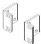
1 x Set of Rack ears
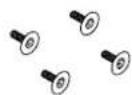
4 x M3 X 6mm Countersunk Pozi screws

2 x Header Plug Euroblock 2-

2 x Header Plug Euroblock 4-

10 x Header Plug Euroblock 3-Pole
1 x User Guide (AP10223).
1 x ROHS Addendum Notes (AP7014).
1 x Safety Instructions (AP9240/CL1-1) - PLEASE READ BEFORE CONTINUING WITH THIS MANUAL.
3 Front Panel

3.1 Input Section
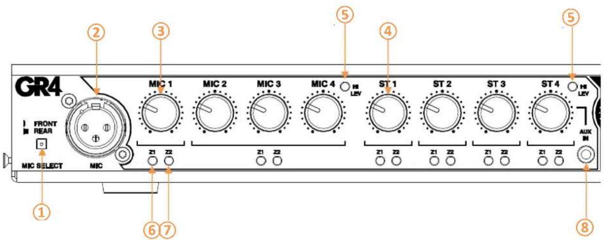
① MIC SELECT – a user selectable switch for MIC 1 input. MIC 1 signal can either be derived from the rear mount Euroblock or front mount XLR connectors. Use pointed object to select switch.
② MIC 1 INPUT – Front mount XLR receptacle for MIC 1 input.
③ MIC LEVEL - Adjustable rotary level control for MIC inputs 1-4. Mic level control of Off to +6dB.
④ST LEVEL – Adjustable rotary level control for LINE inputs 1-4. Line level control of Off to +6dB.
⑤ Hi LEV LED – LED level indicator which illuminates when signal to MIC 1-4 and ST 1 to 4 is approaching clip level. The Hi Level LED illuminates when one or more inputs are at 3dB before clip level.
⑥Z1 SELECTION INDICATOR – LED indicator showing input selection to ZONE 1 mix bus.
⑦Z2 SELECTION INDICATOR – LED indicator showing input selection to ZONE 2 mix bus.
⑧ AUX INPUT – Auxiliary input on 3.5mm jack socket.
This input will override any input connected to ST4 on the rear Euroblock connector.
3.2 Output Section
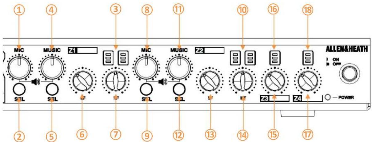
①Z1 MIC MIX OUTPUT LEVEL – Adjustable rotary level control for MIC Mix to Zone 1. Output level control Off to +6dB.
②Z1 MIC SELECT SWITCH – Output Zone Mic selection switch used to add/remove mic sources to/from the output Zone 1 mix signal. The following combinations are supported; Mic 1 only/Mics 2-4 only/All Mics
③Z1 OUTPUT METER - Three-segment LED meter showing L & R output level of Z1 Mix. Illumination will occur at -18, +3 and +17dB.
④Z1 MUSIC OUTPUT LEVEL – Adjustable rotary level control of Stereo sources to Zone 1. Output level control Off to +6dB.
⑤Z1 MUSIC SELECT SWITCH – Output Zone Music selection switch used to select Stereo sources to output Zone 1 mix.
⑥Z1 OUTPUT EQ – LF control of Zone 1 output signal. Shelving EQ with +/-15dB with cut-off frequency at 80Hz.
⑦Z1 OUTPUT EQ – HF control of Zone 1 output signal. Shelving EQ with +/-15dB with cut-off frequency at 8kHz.
⑧Z2 MIC MIX OUTPUT LEVEL – Adjustable rotary level control for MIC Mix to Zone 2. Output level control Off to +6dB.
⑨Z2 MIC SELECT SWITCH – Output Zone Mic selection switch used to add/remove mic sources to/from the output Zone 2 mix signal. The following combinations are supported; Mic 1 only/Mics 2-4 only/All Mics.
⑩Z2 OUTPUT METER - Three-segment LED meter showing L & R output level of Zone 2 Mix. Illumination will occur at -18, +3 and +17dB.
⑪Z2 MUSIC OUTPUT LEVEL – Adjustable rotary level control of Stereo sources to Zone 2. Output level control Off to +6dB.
⑫Z2 MUSIC SELECT SWITCH – Output Zone Music selection switch used to select Stereo sources to output Zone 2 mix
⑬Z2 OUTPUT EQ - LF control of Zone 2 output signal. Shelving EQ with +/-15dB with cut-off frequency at 80Hz.
⑭Z2 OUTPUT EQ – HF control of Zone 2 output signal. Shelving EQ with +/-15dB with cut-off frequency at 8kHz.
⑮Z3 MIX OUTPUT LEVEL – Adjustable rotary level control of Mix to Zone 3. Output level control Off to +6dB.
⑯Z3 OUTPUT METER - Three-segment LED meter showing mono output level of Zone 3 Mix. Illumination will occur at -18, +3 and +17dB.
⑰Z4 MIX OUTPUT LEVEL – Adjustable rotary level control of Mix to Zone 4. Output level control Off to +6dB.
3.3 General
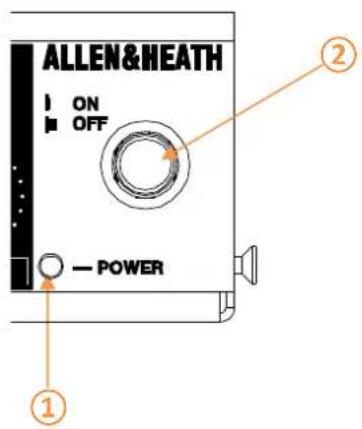
⑱Z4 OUTPUT METER - Three-segment LED meter showing mono output level of Zone 4 Mix. Illumination will occur at -18, +3 and +17dB.
① POWER INDICATOR – LED indicator showing the unit has power. Also used to indicate when unit is in ‘Programming’ mode (see section 6.4).
② MAINS SWITCH – Switch to power the unit ON/OFF.
Note: The mains button can be removed and replaced with a blanking bung to avoid accidental powering off of the unit.
4 Rear Panel

4.1 General
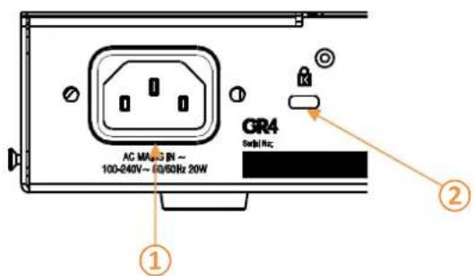
① AC POWER
IEC receptacle to connect mains power cable (included). 100V to 240V accepted.
② KENSINGTON LOCK
Kensington lock cut-out for securing unit.
4.2 Control Section
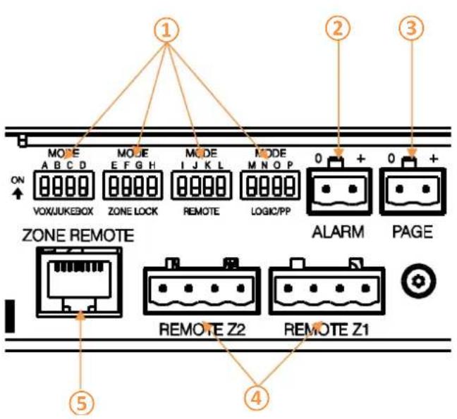
① DIP SWITCHES
Dip switches used to control priority settings, zone lock, remote operation and contact closure configuration.
(See section 6.3 for detailed description).
4.3 Output Section
② ALARM INPUT
Contact closure (DIP switch option for Normally Open/Closed) for emergency input detect. On activation all inputs will fade to the pre-set level except for Mic 1 and Z1 &Z2 LED's will flash quickly. Normal operation will resume once contact is reset to original state.
③ PAGE INPUT
Contact closure (DIP switch option for Normally Open/Closed) for paging announcements. On activation all inputs will fade to the pre-set level except for Mic 1 and Z1 & Z2 LED's will flash slowly. Normal operation will resume once contact is reset to original state.
④ANALOGUE ZONE REMOTE
4-pole Euroblock connector for connection of custom or 3 ^rd party volume and/or source selection panels.
(See section 6.6 for detailed description).
⑤ DIGITAL ZONE REMOTE
RJ45 connector for use with the Allen & Heath PL-14 remote controller.
(See section 6.6 for detailed description).
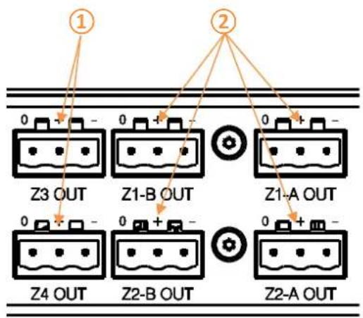
①Z3 & Z4 OUTPUTS
Mono, balanced zone outputs on Euroblock connector.
②Z1 & Z2 OUTPUTS
Stereo (mono configurable via internal jumpers) balanced outputs on Euroblock connector.
4.4 Input Section
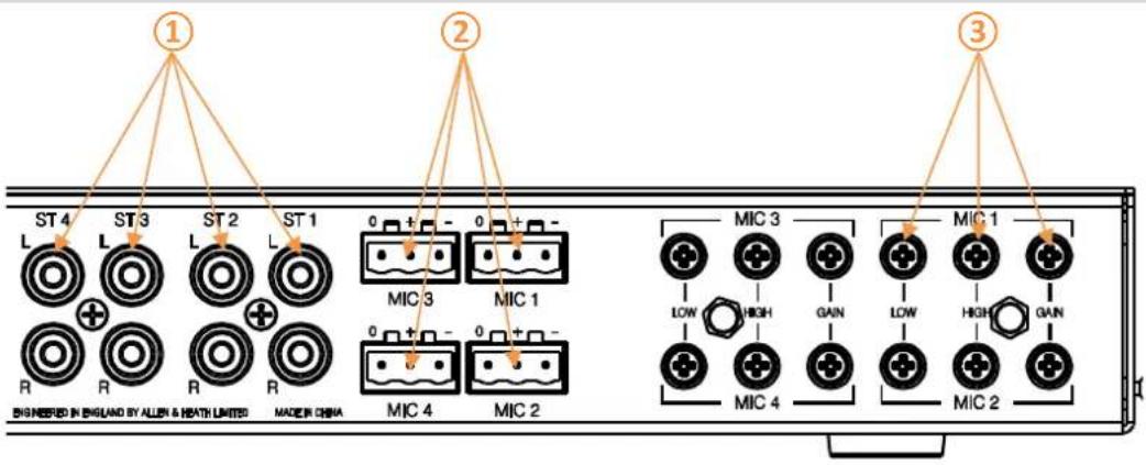
① STEREO INPUTS
Line level inputs 1 to 4 on unbalanced phono connectors.
Note: Unloaded Phono connectors can induce noise on the output if the input level is not on the fully off position. Either ensure unused channels have Zero Gain/Level or use termination connectors on unused inputs.
② MIC INPUTS
Microphone input on balanced Euroblock connector.
Note: Mic 1 is selectable between rear Euroblock and front mount XLR via front mount switch.
③ MIC INPUT ADJUSTMENT
Microphone gain, Lo and Hi EQ trim pots used to adjust the input sensitivity of the pre-amplifier channel* and to adjust the EQ setting of the MIC channel.
\*Setting the channel gain
- Connect the microphone to be used with the associated input.
- Speak into the microphone whilst adjusting the gain trim with a small flat blade screwdriver.
- Adjust the trim until the Hi Lev LED illuminates and then trim back the level slightly so it no longer illuminates.
- Further adjustments may be required to suit the dynamics of the users' normal range.
5 Installing GR4
5.1 Mounting the unit
The GR4 can be used as a stand-alone unit and placed on a hard surface or rack-mounted in a standard 1U 19" profile.
You will need the following items;
• T8 Torx screwdriver
- Small flat blade screwdriver
- Rack ears (supplied)
• 4 x M3 Torx screws (supplied)
- Posi Screwdriver
- 4 x M6 Screws
To rack-mount the unit follow the below procedure;
- Using the supplied rack ears and M3 Torx screws fit to the unit as in the below diagram.
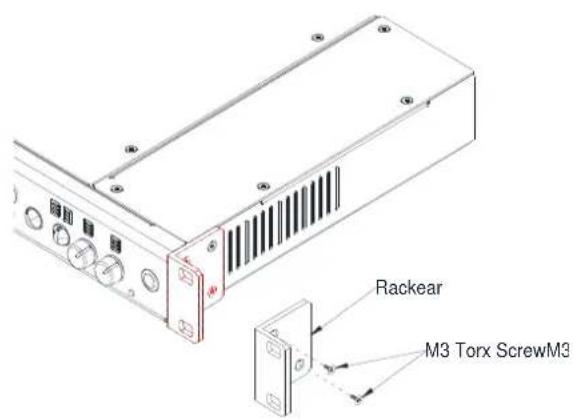
Be sure to use the supplied screws or exact replacements (damage to internal PCB's can result when using longer screws).
- Using the small flat bladed screwdriver gently remove the four rubberized feet on the base of the unit.
Gently prize the central plastic grommet away from the unit. Once removed the rubberized feet can be stored safely for future use.
To reinstate simply push the grommet into place.
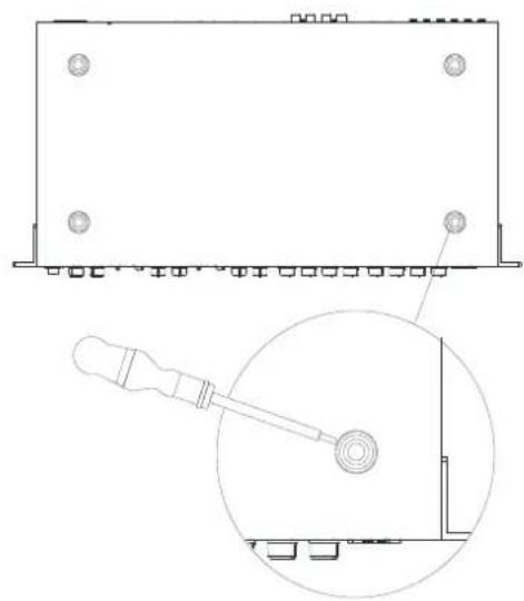
natural_image
Technical line drawing of a rectangular electronic device with mounting holes and a magnified inset showing internal components (no text or symbols)- Install within the 19" rack making sure the unit is secure.
Please ensure you have enough depth within the rack to accommodate the GR4 together with sufficient cable bending radius (the GR4 is 220mm deep).
Note: Please ensure adequate ventilation is provided and the sides of the unit are not obstructed to maintain adequate airflow.
6 Connecting to GR4
6.1 Microphone Inputs
Microphone inputs are balanced connections on Euroblock type connectors.
Pin assignments are screen printed above the connector or alternatively use the below wiring diagram.
Refer to 4.4 Input Section ② for location details
XLR to Euroblock (Balanced to Balanced)
$$ \begin{array}{l} 0 = \text { Screen (Pin 1) } \ + = \text { Hot (Pin 2) } \ - = \text { Cold } (\text { Pin } 3) \ \end{array} $$
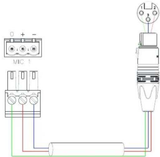
Balanced microphone input wiring example.
6.2 Stereo Inputs
Line level stereo inputs are unbalanced on RCA connectors.
Refer to 4.4 Input Section ① for location details
RCA to RCA (Unbalanced to Unbalanced)
$$ \begin{array}{l} \text { Tip } = \text { Tip } \ \text { Sleeve } = \text { Sleeve } \ \end{array} $$
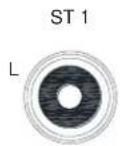
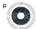
UNBALANCED SOURCE
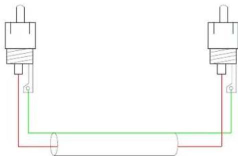
natural_image
Pure electrical circuit lines without any symbolsUnbalanced line input wiring example.
XLR/Euroblock (Transformer or Cross-Coupled Output) to RCA
Screen (Pin 1) = Link to Pin 3
Hot (Pin 2) = Tip
Cold (Pin 3) = Sleeve
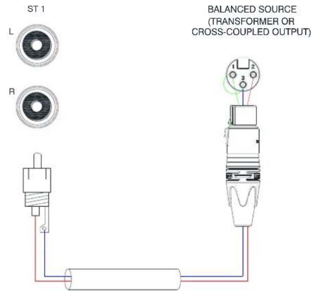
Balanced to Unbalanced input wiring example.
6.3 Zone Outputs
Zone outputs are balanced connections on Euroblock type connectors.
Pin assignments are screen printed above the connector or alternatively use the below wiring diagrams.
Refer to 4.3 Output Section ① for location details
Euroblock to XLR (Balanced to Balanced)
$$ \begin{array}{l} 0 = \text { Screen } \ + = \text { Hot } \ - = \text { Cold } \ \end{array} $$
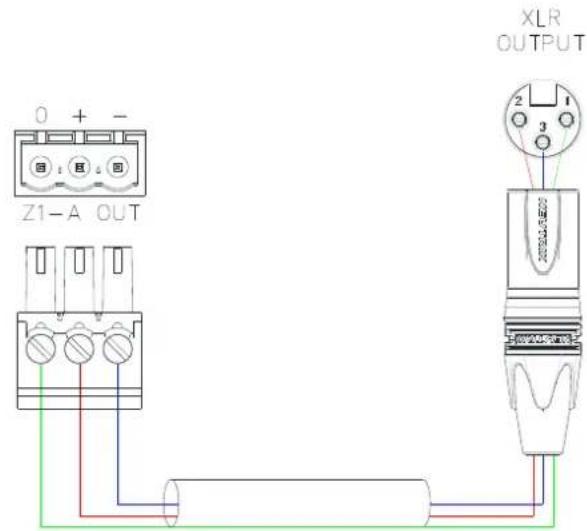
Balanced line output (XLR) wiring example.
Euroblock to TRS (Balanced to Balanced)
$$ \begin{array}{l} 0 = \text { Sleeve } \ + = \text { Tip } \ - = \text { Ring } \ \end{array} $$
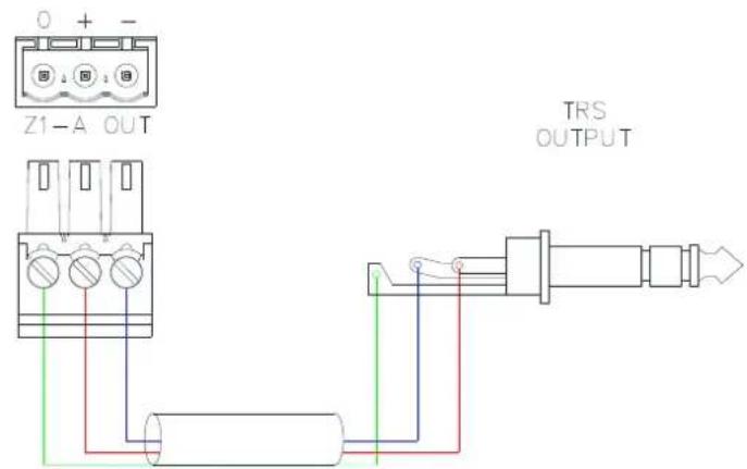
Balanced line output (TRS) wiring example.
Euroblock to RCA (Balanced to Unbalanced)
0 = Link to Negative
+ = Tip
- = Sleeve
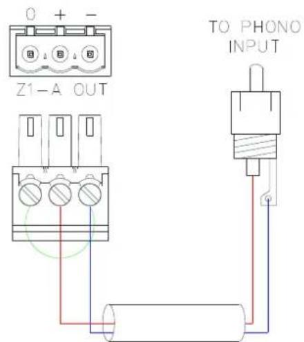
Balanced line output (Phono) wiring example.
6.4 Alarm Input
The Alarm input is a 2-pole connection on Euroblock type connector and is typically configured to the Normally Closed contacts. Pin assignments are screen printed above the connector or alternatively use the below wiring diagrams.
Refer to 4.2 Control Section ② for location details
2-Wire Alarm Contact Closure
$$ \begin{array}{l} 0 = \mathrm{COM} \ + = \mathrm{N} / \mathrm{O} (\text { or } \mathrm{N} / \mathrm{C}) \ \end{array} $$
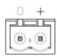
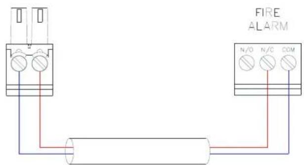
2-wire contact example.
6.5 Page Input
The Page input is a 2-pole connection on Euroblock type connector and is typically configured to the Normally Open contacts. Pin assignments are screen printed above the connector or alternatively use the below wiring diagrams.
Refer to 4.2 Control Section ③ for location details
2-Wire Paging Switch
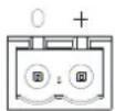
$$ 0 = \mathrm{COM} $$
$$ + = \mathrm{N} / \mathrm{O} (\text {or N} / \mathrm{C}) $$
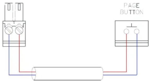
2-wire switch example.
6.6 Remote Connection
There are two methods for connecting a remote control to the GR4. Remote control is enabled via the rear mount dip switches.
Digital Remote Connection
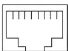
The RJ45 “ZONE REMOTE” port allows for the connection of the Allen & Heath PL-14 remote controllers. A maximum of two PL-14’s can be connected in daisy-chain wiring with various control options depending on installation requirements (see PL-14 manual for additional details regarding cable types and length).
Refer to 4.2 Control Section ⑤ for location details

Do not connect remote port to anything other than the designated remote controller.
Digital Remote (RJ45 to RJ45)
1 = White/Orange
2 = Orange
3 = White/Green
4 = Blue
5 = White/Blue
6 = Green
7 = White/Brown
8 = Brown
ZONE REMOTE
PL-14
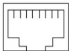
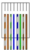
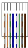
RJ45 Wiring Example using TIA/EIA 568B standard.
Analogue Remote Connection
The analogue inputs are 4-pole Euroblock type connectors for Zone 1 & Zone 2 control. These are 0-10V inputs and are typically used as a variable resistance and stepped voltage control for analogue volume control and source selection.
Pin assignments are screen printed above the connector or alternatively use the below wiring diagrams.
Refer to 4.2 Control Section ④ for location details
4-Wire Analogue Remote
$$ \begin{array}{l} 0 = 0 \mathrm{V} \ L = \text { L e v e l } \ S = \text { Source } \ + = 1 0 \mathrm{V} \ \end{array} $$
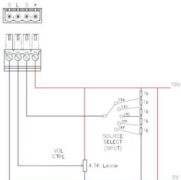
Analogue remote connection example.
7 Setting up GR4
7.1 Operating Features
The GR4 is a feature rich analogue zone mixer. Multiple configurations are possible by means of internal jumpers, external dip switches and also via digital programmable pre-sets.
The below gives an overview of the various Modes that the GR4 enters when signal is sensed on various input connectors.
Primary Mic Mode: When audio sensed on Mic 1 channel and/or PAGE contact closure is sensed then music is faded to pre-set level and Mic 2 muted for the duration of the announcement. Mic 1 zone select LEDs flash slowly when in primary mic mode.
Secondary Mic Mode: When audio is sensed on Mic 2, then music is faded to pre-set level for the duration of the announcement. Mic 2 zone select LEDs flash slowly when in secondary mic mode.
Emergency Mic Mode: When ALARM contact is activated all zone feeds are muted and Mic 1 is fed direct to all zones. All select LEDs except Mic 1 LED are switched off for the duration. Mic 1 LED will flash quickly.
Juke Box Mode: Is a priority Music feed. When in Jukebox mode and audio is sensed on ST3 the current music feed will 'duck'* to the pre-set level. If ST3 is silent for the pre-set period, the previous Music selection will resume. Mic volume is not affected by Jukebox priority.
*Pre-set levels for the above modes are achieved via a side-chain compressor or 'ducker'. A ducker is dynamic control of Input x by input y which has a higher priority. If audio is detected at Input y then Input x will be 'Ducked' by a predetermined level which can be set by the user (see Table 1 6.4 for user definable parameters). In addition to the amount of attenuation is applied to the
'Ducked' signal the user can also control the hold time and release time of the compressor to suit the application.
7.2 Internal Jumper Settings

Please ensure that unit is switched off before changing any jumper settings. Ensure necessary precautions have been taken prior to removal of cover. If in doubt call an experienced engineer.
Warning: Do not remove PSU cover. If in doubt call an experienced engineer.
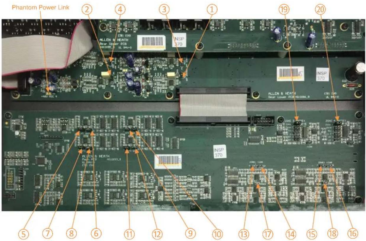
Jumper Function
| 1 | MIC 1 High Pass Filter @ 150Hz | Filter Inactive | Filter active |
| 2 | MIC 2 High Pass Filter @ 150Hz | Filter Inactive | Filter active |
| 3 | MIC 3 High Pass Filter @ 150Hz | Filter Inactive | Filter active |
| 4 | MIC 4 High Pass Filter @ 150Hz | Filter Inactive | Filter active |
| 5 | ST1 L Gain | +10dB | 0dB |
| 6 | ST1 R Gain | +10dB | 0dB |
| 7 | ST2 L Gain | +10dB | 0dB |
| 8 | ST2 R Gain | +10dB | 0dB |
| 9 | ST3 L Gain | +10dB | 0dB |
| 10 | ST3 R Gain | +10dB | 0dB |
| 11 | ST4 L Gain | +10dB | 0dB |
| 12 | ST4 R Gain | +10dB | 0dB |
| 13 | Zone 1 A Gain | -10dB | +4dBu |
| 14 | Zone 1 B Gain | -10dB | +4dBu |
| 15 | Zone 2 A Gain | -10dB | +4dBu |
| 16 | Zone 2 B Gain | -10dB | +4dBu |
| 17 | Zone 1 Mono | Zone 1 mono output | Zone 1 stereo output |
| 18 | Zone 2 Mono | Zone 2 mono output | Zone 2 stereo output |
| 19 | Zone 3 Mix | Multiple Configurations (see matrix p18) | No output |
| 20 | Zone 4 Mix | Multiple Configurations (see matrix p18) | No output |
Zone 3 & 4 are mixed from a matrix on internal jumpers. The unit is shipped with the below settings as default but both zones can have any number of jumpers applied to suit the application.
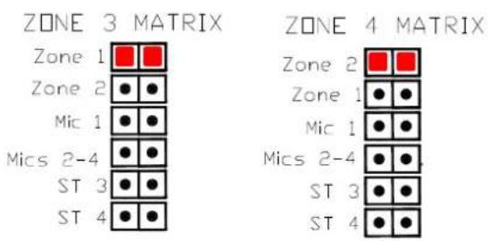
Zone 3 & 4 Matrix Mix Default Positions
7.3 Dip Switch Settings
There are 16 Rear mounted DIP switches for selecting various options.
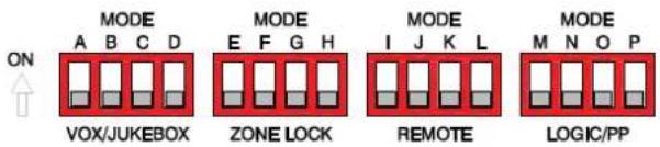
DIP switch settings Up = ON. Factory default = all switches down (OFF).
| A | Mic 1 Level Paging Detect | Switches Primary Mic mode (ON) |
| B | Mic 2-4 Level Paging Detect | Switches Secondary Mic mode (ON) |
| C | Jukebox Mode Z1 | Switches Jukebox mode in Zone 1 (ON) |
| D | Jukebox Mode Z2 | Switches Jukebox mode in Zone 2 (ON) |
| E | Z1 Mic Select Lock | Locks the front MIC SEL switch for Z1 (ON) |
| F | Z1 Music Select Lock | Locks the front MUSIC SEL switch for Z1 (ON) |
| G | Z2 Mic Select Lock | Locks the front MIC SEL switch for Z2 (ON) |
| H | Z2 Music Select Lock | Locks the front MUSIC SEL switch for Z2 (ON) |
| I | Z1 Volume Local/Remote Control | Enables Z1 remote volume control (ON) |
| J | Z1 Stereo Input Local/Remote Control | Enables Z1 remote source select (ON) |
| K | Z2 Volume Local/Remote Control | Enables Z2 remote volume control (ON) |
| L | Z2 Stereo Input Local/Remote Control | Enables Z2 remote source select (ON) |
| M | PAGE logic invert | Normally Open (OFF) Normally Closed (ON) |
| N | ALARM logic invert | Normally Open (OFF) Normally Closed (ON) |
| O | Phantom Power Enable Mic 1 | Enables Phantom Power MIC 1 (ON) |
| P | Phantom Power Enable Mics 2-4 | Enables Phantom Power MICS 2-4* (ON) |
*Phantom Power for individual mics can be disconnected via an internal link (as shown in internal jumper diagram) Please ensure mic levels are fully attenuated prior to engaging phantom power.
7.4 Programming Parameters
The GR4 has a total of 7 parameters (shown in Table 1) which are configurable by the installer/user.
Each parameter has four pre-defined values which can be stepped through and set as required.
Changing a Parameter Step by Step Guide- Ensure amplifiers/powered speakers are switched off prior to powering the unit up or down.
To enter Programming Mode;
- Press and hold Z1 Mic & Music "SEL" switches
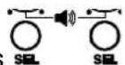
GR4

- Power LED - POWER will flash continuously whilst in Programming Mode.
Changing a parameter;
- Use Z2 Mic & Music "SEL" switches
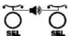
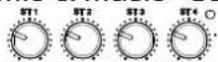
change as shown in Table 1.
to toggle through the parameter to
- Use Z1 Mic & Music "SEL" switches
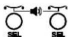
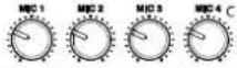
required as shown in Table 1.
to toggle through the value
- The new parameter value is stored automatically. The parameter LED will flash quickly during the save procedure.
Exit Programming Mode;
- Power cycle the unit

to return to normal operation, LED will remain solid

| Value | 1 | 2 | 3 | 4 | |
| Parameter | LED | MIC1 Z1 | MIC1 Z2 | MIC2-4 Z1 | MIC2-4 Z2 |
| 1 Ducker Attenuation | ST1 Z1 | -12dB | -20dB | -30dB | OFF |
| 2 Ducker Hold Time | ST1 Z2 | 500mS | 1.5s | 5s | 10s |
| 3 Ducker Release Time | ST2 Z1 | 500mS | 1.5s | 5s | 20s |
| 4 Music Crossfade Time | ST2 Z2 | 50mS | 200mS | 500mS | 3s |
| 5 Jukebox Attack Time | ST3 Z1 | 50mS | 200mS | 500mS | 1s |
| 6 Jukebox Hold Time | ST3 Z2 | 1s | 3s | 5s | 20s |
| 7 Jukebox Release Time | ST4 Z1 | 500mS | 1.5s | 3s | 10s |
Table 1 – Showing Parameter/Value/LED State matrix. (Factory settings highlighted).
8 FAQ
Q: What are the main differences between the GR4 and GR2?
A: The GR4 has an additional stereo zone output together with two additional mono zone outputs which can be individually set to one of six pre-set mixes. Each microphone input has individual tone control. Additional connectors have been added to the front panel in the form of an XLR Mic input for priority announcements and a 3.5mm socket has been added for connection of MP3 players. The ability to control the mix of mic and music sources on zone outputs 1 & 2.
Q: My audio sources keep fading in and out?
A: It is likely that one or more dip switches have been set to the "ON" position. The GR4 has various "MODES" that allow priority control of the incoming signals.
- Primary Mic Mode (Dip Switch A). This will automatically mute mics 2-4 and fade the music sources to a pre-defined level.
- Secondary Mic Mode (Dip Switch B). This will automatically fade the music sources to a pre-defined level.
- Jukebox Mode (Dip Switch C & D). This will fade down the music on all stereo inputs except for ST3 which is set as the Jukebox priority input.
Q: Can I control the unit over a standard network?
A: No, the rear RJ45 port is for use with Zone remote panels only and is not intended for connection to a network switch.
Q: How do I control the unit remotely?
A: Remote control can be achieved by either using the optional Allen & Heath PL-14 controller or via custom wired control. The "ZONE REMOTE" RJ45 port on the rear of the unit will accept up to two PL-14's which are
connected in a 'daisy-chain' configuration. An optional PL-5 remote is also available for Infrared control of the PL-14. Alternatively a custom or 3^rd party 0-10v controller can be wired to the "REMOTE Z1" and/or "REMOTE Z2" connectors on the rear of the unit.
Q: I want to change some of the processors software parameters?
A: These options can be accessed by holding down Z1 select buttons whilst powering the unit.
- Mic ducking attenuation, hold and release speeds.
• Music cross fade speed. - Juke box attack, hold and release speed.
Q: Can I change the routing options to Zones 3 & 4?
A: Yes, Zones 3 & 4 are factory set to output the mix of Zone 1 & 2 respectively. Utilising one or a multiple of the internal jumpers it is possible to create an entirely independent mix on both Zone 3 & 4. The jumper options are as below.
- Jumper 1 (Default) – Zone 1 mix (Zone 2 mix is default for Zone 4)
- Jumper 2 – Zone 2 mix (Zone 1 mix for Zone 4)
- Jumper 3 – Mic 1 only (for both Zone 3 & 4)
- Jumper 4 – Mics 2-4 only (for both Zone 3 & 4)
- Jumper 5 – ST3 only (for both Zone 3 & 4)
- Jumper 6 – ST4 only (for both Zone 3
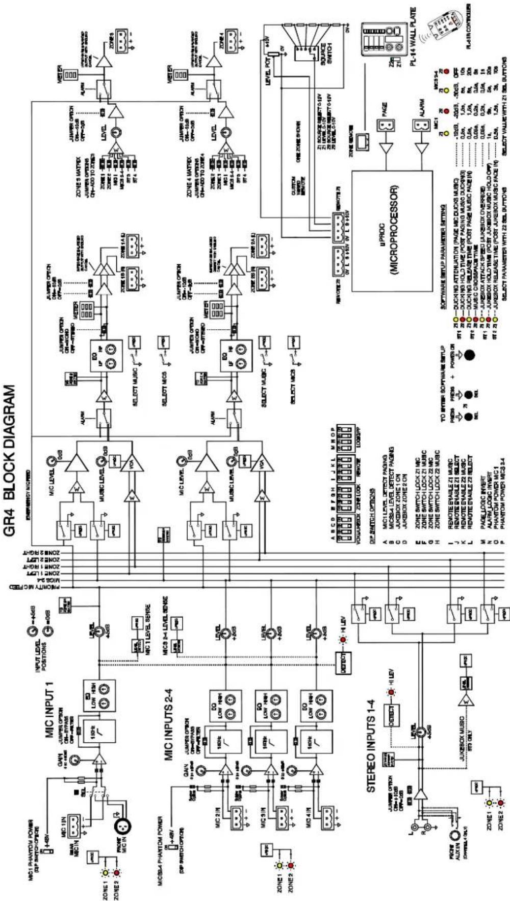
9 Block Diagram
flowchart
GR4 Block Diagram for microprocessor control system, showing connections between MIC INPUT 1, MIC INPUTS 2-4, STEREO INPUTS 1-4, and microprocessor modules.10 Specifications
| Microphone Inputs | ||
| Mic Input Sensitivity (Gain = Min) | 0dBu | |
| Mic Input Sensitivity (Gain = Max) | -50dBu | |
| Mic Level control (Max) | +6dB | |
| Mic Level control (Min) | OFF | |
| Mic HPF -3dB | 150Hz | |
| Mic EQ LF | +/- 15dB fc = 60Hz | |
| Mic EQ HF | +/-15dB fc = 9kHz | |
| Mic Frequency Response 20Hz – 20kHz | +/-1dB | |
| Mic THD+n @0dBu in 1kHz | 0.004% 22-22kHz | |
| Mic THD+n @-30dBu in 30dB gain 1kHz | 0.005% 22-22kHz | |
| Mic Hi Level warning LED (Unity gain) | +18dBu | |
| Clip level (Unity gain) | +21dBu | |
| Mic EIN@50dB Gain | -127dB | |
| Stereo Inputs | ||
| ST Input Sensitivity (Gain link OFF) | 0dBu | |
| ST Input Sensitivity (Gain Link ON) | -10dBu | |
| ST Level control (Max) | +6dB | |
| ST Level control (Min) | OFF | |
| Max Line Input | +18dBu | |
| ST Frequency response 20Hz – 20kHz | +/-0.5dB | |
| ST THD+n @-10dBu in 1kHz | 0.015% 22-22kHz | |
| ST THD+n @0dBu in 1kHz | 0.035% 22-22kHz | |
| Crosstalk from unselected channel | -75dB @ 1kHz | |
| Zone Outputs | ||
| Nominal Zone Level | 0dBu (-10dBu with optional jumper) | |
| Main Zone Level control (Max) | 0dB | |
| Main Zone Level control (Min) | OFF | |
| Main Zone 3 Segment LED Meter | -18/+3/+17dBu | |
| Main Zone EQ LF | +/-15dB fc = 60Hz | |
| Main Zone EQ HF | +/-15dB fc = 9kHz | |
| Main Zone Clip level (Unity gain) | +21dBu | |
| Alarm/Page Inputs | ||
| Max/Min Voltage | +15/-15V | |
| Input source/sink | Max 5mA | |
| Off Threshold | <0.2V | |
| On Threshold | >1V | |
| Noise | ||
| ST Input to Main Zone output (Unity) | -90dBu 22-22kHz | |
| Mic Input routed at Min gain | -88dBu 22-22kHz | |
| Mic Input routed at Max gain | -77dBu 22-22kHz (150R source) | |
| Power Consumption | ||
| GR4 unit (no remote attached) | 15W | |
| Loaded Power (Max) | 20W | |
| Weights & Dimensions | ||
| Unboxed | Boxed | |
| Height | 48mm (1.9") | 200mm(7.9") |
| Length | 242mm (9.5") | 340mm(13.4") |
| Width | 438mm (17.2") | 530mm(20.9") |
| Weight | 3.4kg (7.5lbs) | 4kg (8.8lbs) |
11 Connection Diagram
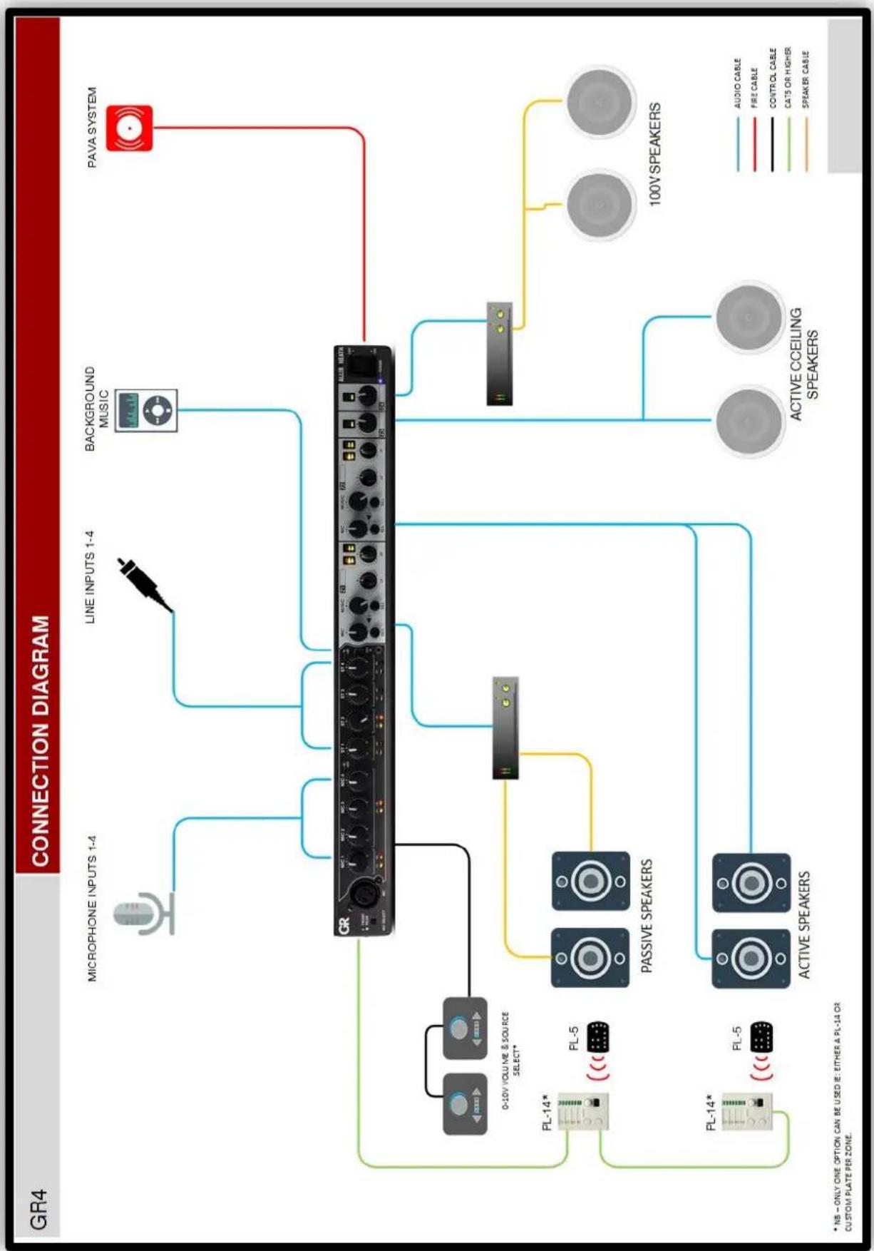
flowchart
graph TD
    A["GR4"] --> B["MICROPHONE INPUTS 1-4"]
    A --> C["LINE INPUTS 1-4"]
    A --> D["BACKGROUND MUSIC"]
    A --> E["PAVA SYSTEM"]
    B --> F["0-10V VOLUME & SOURCE SELECT*"]
    C --> G["PASSIVE SPEAKERS"]
    D --> H["100V SPEAKERS"]
    E --> I["ACTIVE CCEILING SPEAKERS"]
    F --> J["PL-14*"]
    F --> K["PL-5"]
    G --> L["Active SPEAKERS"]
    H --> M["100V SPEAKERS"]
    I --> N["Active CCEILING SPEAKERS"]
    style A fill:#f9f,stroke:#333
    style B fill:#ccf,stroke:#333
    style C fill:#ccf,stroke:#333
    style D fill:#ccf,stroke:#333
    style E fill:#ccf,stroke:#333
    style F fill:#cfc,stroke:#333
    style G fill:#cfc,stroke:#333
    style H fill:#cfc,stroke:#333
    style I fill:#cfc,stroke:#333
    style J fill:#fcc,stroke:#333
    style K fill:#fcc,stroke:#333
    style L fill:#fcc,stroke:#333
    style M fill:#fcc,stroke:#333
12 Application Examples
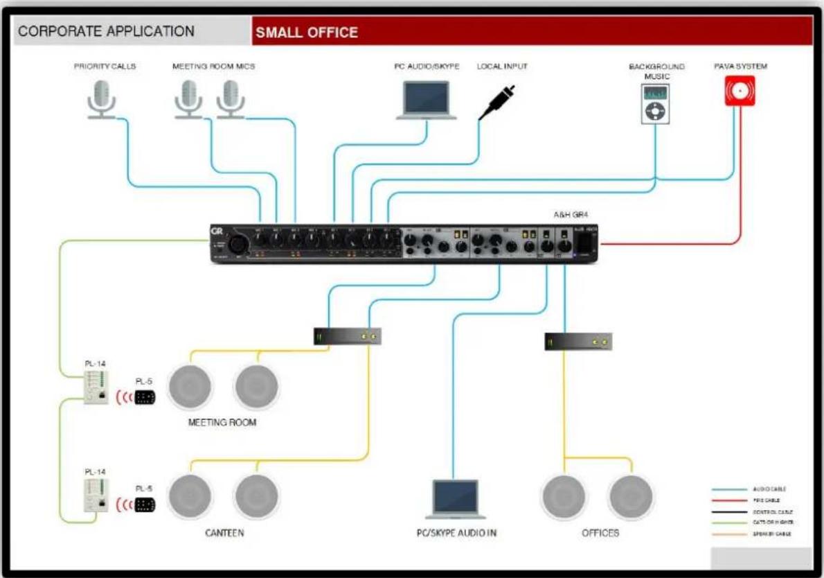
flowchart
graph TD
    A["Corporate Application"] --> B["PRIORITY CALLS"]
    A --> C["MEETING ROOM MICS"]
    A --> D["PC AUDIO/SKYPE"]
    A --> E["LOCAL INPUT"]
    A --> F["BACKGROUND MUSIC"]
    A --> G["PAVA SYSTEM"]
    H["SMALL OFFICE"] --> I["CR"]
    H --> J["A&H GR4"]
    H --> K["MEETING ROOM"]
    H --> L["PC/SKYPE AUDIO IN"]
    H --> M["OFFICES"]
    N["PL-14"] --> O["PL-5"]
    N --> P["PL-5"]
    Q["PL-14"] --> R["PL-5"]
    S["CANTEEN"] --> T["MEETING ROOM"]
    U["PC/SKYPE AUDIO IN"] --> V["POCK/SKYPE AUDIO IN"]
    W["OFFICES"] --> X["POCK/SKYPE AUDIO IN"]
    Y["PRO CABLE"] --> Z["PRO CABLE"]
    AA["CONTROL CASE"] --> AB["CONTROL CASE"]
    AC["CAT/DR IN CHINE"] --> AD["CAT/DR IN CHINE"]
    AE["SPEAK/B CABLE"] --> AF["SPEAK/B CABLE"]
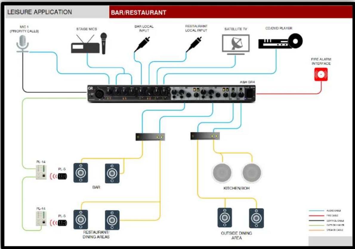
flowchart
graph TD
    A["LEISURE APPLICATION"] --> B["MIC 1 (PRIORITY CALLS)"]
    A --> C["STAGE MICS"]
    A --> D["BAR/RESTAURANT"]
    A --> E["RESTAURANT LOCAL INPUT"]
    A --> F["SATELUTE TV"]
    A --> G["CD/DVD PLAYER"]
    C --> H["A&H GR4"]
    D --> H
    E --> H
    F --> H
    G --> H
    H --> I["PIE ALARM INTERFACE"]
    H --> J["KITCHEN/BOH"]
    H --> K["OUTSIDE DINING AREA"]
    H --> L["RESTAURANT/DINING AREAS"]
    H --> M["PL-5"]
    H --> N["PL-14"]
    H --> O["PL-5"]
    style A fill:#f9f,stroke:#333
    style B fill:#ccf,stroke:#333
    style C fill:#cfc,stroke:#333
    style D fill:#fcc,stroke:#333
    style E fill:#cff,stroke:#333
    style F fill:#ffc,stroke:#333
    style G fill:#fcc,stroke:#333
    style H fill:#ffc,stroke:#333
    style I fill:#cfc,stroke:#333
    style J fill:#fcc,stroke:#333
    style K fill:#cfc,stroke:#333
    style L fill:#fcc,stroke:#333
    style M fill:#cfc,stroke:#333
- Limited One Year Manufacturer's Warranty
- Conditions Of Warranty
- ALLEN&HEATH
- Contents
- Introduction
- 8in / 4out Zone Mixer
- Packed Contents
- Front Panel
- Input Section
- Output Section
- General
- Rear Panel
- General
- Control Section
- ① DIP SWITCHES
- Output Section
- ② ALARM INPUT
- ③ PAGE INPUT
- ④ANALOGUE ZONE REMOTE
- ⑤ DIGITAL ZONE REMOTE
- ①Z3 & Z4 OUTPUTS
- ②Z1 & Z2 OUTPUTS
- Input Section
- ① STEREO INPUTS
- ② MIC INPUTS
- ③ MIC INPUT ADJUSTMENT
- \*Setting the channel gain
- Installing GR4
- Mounting the unit
- Connecting to GR4
- Microphone Inputs
- Stereo Inputs
- XLR/Euroblock (Transformer or Cross-Coupled Output) to RCA
- Zone Outputs
- Euroblock to XLR (Balanced to Balanced)
- Euroblock to TRS (Balanced to Balanced)
- Euroblock to RCA (Balanced to Unbalanced)
- Alarm Input
- 2-Wire Alarm Contact Closure
- Page Input
- 2-Wire Paging Switch
- Remote Connection
- Digital Remote Connection
- Digital Remote (RJ45 to RJ45)
- Analogue Remote Connection
- 4-Wire Analogue Remote
- Setting up GR4
- Operating Features
- Internal Jumper Settings
- Dip Switch Settings
- Programming Parameters
- To enter Programming Mode;
- Changing a parameter;
- Exit Programming Mode;
- FAQ
- Block Diagram
- Connection Diagram
- Application Examples
Brand : ALLEN & HEATH
Model : PL-14
Category : Controller