PC500-FDBFP - Computer LG - Free user manual and instructions
Find the device manual for free PC500-FDBFP LG in PDF.


| Product Type | Mini-PC for Signage |
| Dimensions (W x H x D) | 260 mm x 40.1 mm x 276.75 mm |
| Weight | 2.0 kg |
| Power Rating | 100-240 V~, 50/60 Hz, 1.3 A |
| CPU | Intel® Celeron™ N2920 or N2930 (up to 2.16 GHz) |
| Main Memory | DDR3L 1066 MHz, 2 GB or 4 GB SO-DIMM |
| Secondary Storage | SSD 16 GB, 32 GB, or 64 GB |
| Operating System | Windows® Embedded Standard 7 P |
| Display Output | 1 x DisplayPort (max 1920 x 1080 @ 60 Hz) |
| Other Ports | 1 x RS-232C, 4 x USB 2.0, 1 x Gigabit LAN, 1 x LINE OUT, 1 x Monitor Docking Port |
| Power Consumption (Max) | ≤ 15 W |
| Operating Temperature | 5 °C to 40 °C |
| Storage Temperature | -20 °C to 60 °C |
| Operating Humidity | 10 % to 80 % |
| Storage Humidity | 5 % to 95 % |
| Supported Monitors | **WS50, **LT55A, **WX50MF (LG Electronics) |
| Software Support | SuperSign Manager, LG RS232C protocol |
| Flash Memory Battery | Replaceable CR2032-type battery |
| Mounting | Direct mounting on compatible LG monitors via docking port or guide bracket |
Frequently Asked Questions - PC500-FDBFP LG
User questions about PC500-FDBFP LG
0 question about this device. Answer the ones you know or ask your own.
Ask a new question about this device
Download the instructions for your Computer in PDF format for free! Find your manual PC500-FDBFP - LG and take your electronic device back in hand. On this page are published all the documents necessary for the use of your device. PC500-FDBFP by LG.
USER MANUAL PC500-FDBFP LG
Mini-PC for Signage (Hardware)
Please read this manual carefully before operating the product and retain it for future reference.
Mini-PC for Signage
PC500-A***
PC500-B***
PC500-F***
TABLE OF CONTENTS
Licenses 4
Replacing Flash Memory Battery ....4
PC500-A*** / PC500-B***
Specifications ....5
General Specifications .... 5
Multi I/O Port 5
Operational Specifications 6
Included in the Box 7
Basic Components....7
Optional Items 7
Connections 8
Front 8
Back Panel 8
How to Install on Monitor 9
**WS50, **LT55A Models 9
**WX50MF Model....10
In/Out Cable Connection ....11
Connecting a Monitor with an HDMI Cable 12
Connecting/Disconnecting HDMI Audio Device in Windows 14
Connecting a Monitor with DP Cable 15
Connection to Multiple Monitors 18
PC500-F\*\*\*
Specifications 20
General Specifications 20
Multi I/O Port 20
Operational Specifications 21
Included in the Box 22
Basic Components 22
Optional Items 22
Connections 23
Front Panel....23
Back Panel 23
How to Install on Monitor 24
**WS50, **LT55A Models 24
**WX50MF Model....25
How to Install the Guide Bracket ....26
In/Out Cable Connection ....28
Connecting a Monitor with DP Cable 29
Connecting/Disconnecting DP Audio Device in Windows 32
Connection to Multiple Monitors 33
Limitations of Microsoft Windows Embedded Standard .....35
Frequently Asked Questions (FAQs) 35
Unified Codecs ....36
Network Setting 36

Attention
- LG Electronics does not guarantee the service of the OS not included in the purchase of the product.
Licenses
Supported licenses may differ by model. For more information of the licenses, visit www.lg.com.

HDMI, the HDMI logo and High-Definition Multimedia Interface are trademarks or registered trademarks of HDMI Licensing LLC.

Note
- It may differ depending on the product.
Replacing Flash Memory Battery
The flash memory battery helps maintain the system (BIOS) settings when the computer is powered off. The flash memory battery is a consumable part.


Attention
- When you change the flash memory battery, it is recommended that you seek assistance from the LG Electronics Service Center.
- Using a non-standard battery may cause a malfunction.
- If a malfunction is caused by trying to replace a part on your own, servicing will be charged.
- If the product is not connected to the AC power for an extended period of time, the flash memory battery may be discharged. In this case, servicing will be charged.
- When the battery is discharged, the message below will appear on the boot screen. In this case, you should replace the battery.
=> ERROR
0271: Check data and time settings
WARNING
0251: System CMOS checksum bad - Default configuration used
Press
Specifications

Attention
- Product specifications may change without prior notice to improve performance.
General Specifications
| Dimensions 260 mm (W) x 40.1 mm (H) x 275.9 mm (D) (only Set) | |
| Weight 2.08 Kg (only Set) | |
| CPU | Intel®Celeron Processor P4500 (2M Cache, 1.86 GHz) |
| Intel®CoreTM i5-520M Processor (3M Cache, 2.40 GHz) | |
| Chip Set Mobile Intel QM57 Express Chipset | |
| Main Memory DDR3 1333 $ODIMM type 2 GB | |
| Secondary Storage Device | SSD 8 GB, 16GB, 32 GB, 64 GB |
| O/S | Microsoft®Windows Embedded StandardMicrosoft®Windows Embedded Standard 7 EMicrosoft®Windows Embedded Standard 7 P |

Note
Windows 7 is not supported in case of SSD 8 GB.
Multi I/O Port
| Serial Port One external RS-232 Serial port |
| USB Port Hi-Speed USB 2.0 port 480 Mbps rate (x4) |
| LAN Port Intel 82577 Gigabit Ethernet PHY |
| HDMI / DP Intel HD Graphics Controller |
| Mini PCIe Supported |
| LINE OUT Supported |
Operational Specifications
| Resolution | Maximum Resolution | DP: 2560 x 1600 @60 HzHDMI: 1920 x 1200 @60 Hz | ||
| Recommended Resolution | 1920 x 1080 @60 Hz | |||
| Power | Power Rating 100-240 V~ 50/60 Hz 1.3 A | |||
| Operating Condition | Sync (H/V) Video | LED | ||
| Normal Mode On/On Active On | ||||
| Deep Sleep Mode(Set = Off) | Off/Off Off Off | |||
| Operating Conditions | Operating Conditions 5 °C to 40 °C | Humidity 10 % to 80 % | ||
| Storage Conditions -20 °C to 60 °C | Humidity 5 % to 95 % | |||

Note
- The resolution which is supported may differ depending on the monitors.
- Booting the PC500 using a device connected via a USB port may not work properly, depending on the device.
Included in the Box
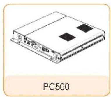
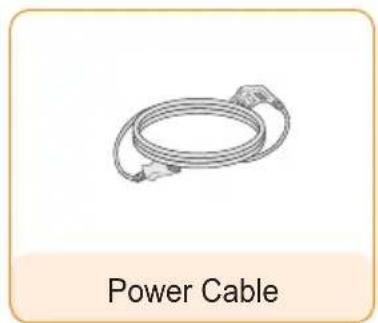
Basic Components
The PC500 with the following components. Please check that these components have been included prior to installation.
natural_image
Isometric illustration of a device labeled 'PC500' (no other text or symbols)
natural_image
Line drawing of a power cable with connectors, labeled 'Power Cable' below (no other text or symbols)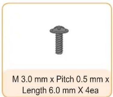

Attention
• These illustrations may differ from your product and are subject to change.
- In some countries, a Y-type cable may be provided instead of the power cord.
- Always use genuine components to ensure safety and product life. Any damages or injuries by misuse or using an improper accessory are not covered by the warranty.
Optional Items
The following items are supported by the PC500, but are not provided with the product.
Please purchase optional items as needed.
- HDMI cable, DP cable, LINE-OUT cable, LAN cable, mouse, keyboard.
Connections
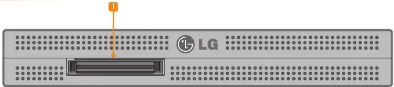
Front
natural_image
Front view of a LG server rack with indicator lights and port (no text or symbols on the device itself)Back Panel
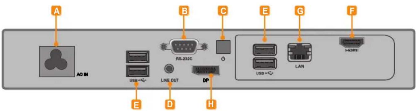
| Number | Connection Description | |
| A | Power Cable In For the power cable. | |
| B | RS-232C Out For the RS-232C cable. | |
| C | Power Button Turns PC500 on. | |
| D | LINE-OUT Connector For a LINE-OUT cable for analog audio transfer. | |
| E | USB In | For USB-type devices, including memory, hard disk, CD-ROM, key-board, and mouse. |
| F | HDMI Out For an HDMI-compatible monitor. | |
| G | LAN Connector For a LAN cable. | |
| H | DP Output Port Connects the cable to the DP-supporting monitor. | |
| I | Monitor Docking Port Connects the PC500 to a monitor. |
How to Install on Monitor
\*\*WS50, \*\*LT55A Models
We recommend you to use the items provided with your PC500 and follow our instructions for integrating the product with your monitor in order to ensure the correct results.

Attention
The illustrations shown are to guide your integration and may differ from your product.
1
Place a soft cloth on the table and put the product with the screen facing downward. Push the PC500 into the compartment to mount it.

natural_image
Technical line drawing of a device chassis with a magnified inset showing internal components (no text or symbols)
Attention
- Be careful of sharp edges on the rail and the handle.
- Fixing the product with non-standard screws may cause damage or the product to fall down. LG Electronics is not liable for any accidents relating to the use of non-standard screws.
- Do not over tighten the screws as this may cause damage to the product and void your warranty."
2
Attach the PC500 on the set using the four screws provided.

\*\*WX50MF Model
For proper use, it is recommended to use the basic components provided with the PC500 to attach it to a monitor.

Attention
The illustrations shown are to guide your integration and may differ from your product.
1
Place a soft cloth on the table and put the product with the screen facing downward. Remove the opening cover by unfastening two screws as shown in the picture.

natural_image
Technical line drawing of a mechanical assembly with two magnified views showing internal components (no text or symbols)2
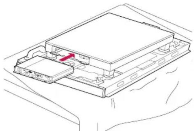
Push the PC500 into the compartment to mount it.
natural_image
Technical line drawing of a computer drive chassis with an internal component and a red arrow indicating a specific part (no text or symbols present)3
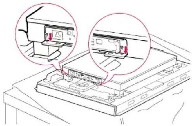
Attach the PC500 on the product using the two screws provided.
natural_image
Technical line drawing of a device with two circular insets showing internal components (no text or symbols)
Attention
- Be careful of sharp edges on the rail and the handle.
- Attaching the product with non-standard screws may cause damage or the product to fall down. LG Electronics is not liable for any accidents relating to the use of non-standard screws.
- Do not over tighten the screws as this may cause damage to the product and void your warranty.
In/Out Cable Connection
To view images on the monitor that is not connected to the monitor docking port of PC500, you need to connect the PC500 to the monitor via an HDMI or DP cable.

Attention
- HDMI, DP, LINE-OUT, and LAN cables are not included in the basic components. You need to purchase a cable separately as it is not provided as an accessory.
- After cabling is complete, assign the SET ID of the monitor to be connected to PC500.
- To configure the SET ID, please refer to the owner's manual for your monitor.

Note
When using the SuperSign Manager software:
- The monitor's SET ID is a unique number used to identify the monitor. You can choose a number from 1 to 25. The SET ID allows the SuperSign Manager software to identify the monitor.
- In order to directly connect the monitor to the PC500, its SET ID must be set to 1.
- To use SuperSign Manager, the monitor that will be connected to a PC500 must support the LG RS232C protocol. A monitor supporting the LG RS232C protocol can be controlled the monitor functions, such as brightness and sound, using SuperSign Manager.
Connecting a Monitor with an HDMI Cable
HDMI connections allow digital video and audio signals to be transferred with one cable. HDMI cable connections do not require an additional audio in cable.

Attention
- The monitor to connect with PC500 should have the HDMI in for the HDMI connection.
- To use an HDMI device, connection should be done on the Windows, the operating system of PC500. To connect and disconnect the HDMI audio device, see the Connecting/Disconnecting HDMI Audio Device in Windows section of this document.
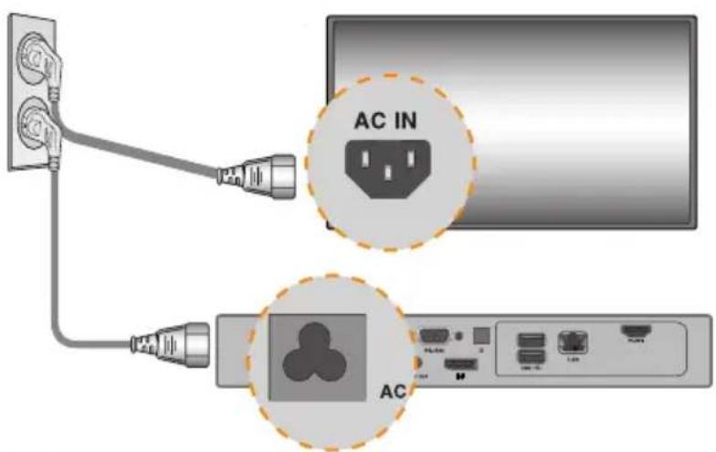
1 Connect the appropriate power cables to a monitor and PC500 respectively.
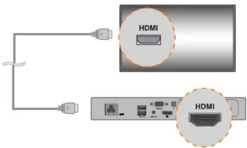
2Connect PC500 to a monitor with an HDMI cable.
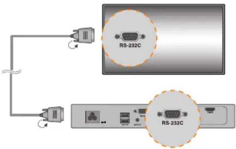
3Connect PC500 (OUT) to the monitor (IN) with an RS-232C cable.

4Connect a LAN cable to PC500.

Connecting/Disconnecting HDMI Audio Device in Windows
Connecting HDMI Audio Device
Move to the desktop of the monitor connected to the PC500.
1 Click the start button in the lower left of the screen.
2 Select Start > Control Panel > Sounds and Audio Devices > Audio.
3 Select Play Sounds > Intel(R) Display Audio Output 1 from the list and click OK.
Disconnecting HDMI Audio Device
Move to the desktop of the monitor connected to the PC500.
1 Click the start button in the lower left of the screen.
2 Select Start > Control Panel > Sounds and Audio Devices > Audio.
3 Select Play Sounds > Realtek HD Audio output from the list and click OK.
Connecting/Disconnecting HDMI Audio Device in Windows Embedded Standard 7 E,P
1 Select Start > Control Panel > Hardware and Sound > Sound.
2 Click the Play tap first. Right-click on the HDMI device or speakers you want and select Set as Default Device then click OK to connect the HDMI audio device or select Disable to disconnect it.
※ In order to change the audio devices, you may restart the computer.
Attention
- If an audio device is connected or removed while media content is played, you need to stop the content and play again.
- If an HDMI cable is removed from the PC500, sound does not play. In addition, when the cable is reconnected, it may take time before sound plays again.
Connecting a Monitor with DP Cable

Attention
- To enable DP connection, the monitor that will be connected to PC500 must support the DP input port.
- When connecting the DP (DisplayPort) cable, use the standard cable. Using a non-standard cable may cause a malfunction.
1 Connect the appropriate power cables to a monitor and PC500 respectively.

2 Connect PC500 to the monitor via a DP cable.

3 Connect PC500 to the monitor (IN) with an RS-232C cable.
4 Connect the PC500 to the monitor with a LINE-OUT cable.

5
Connect a LAN cable to PC500.


Attention
- PC500 prioritizes video output in the following order: DP → HDMI. If you connect multiple cables simultaneously and turn the product on, video output is prioritized accordingly.
- When the product is turned on after cable connection or the operating system is completely booted, DP and HDMI video output start operating.
- The product does not support a dual mode where DP can be switched either to HDMI or DVI. It is only for DP output.
- The DisplayPort (DP) of the PC500 does not support digital audio output. It is recommended to use it with a line-out cable for analog audio output.
Connection to Multiple Monitors
Multiple monitors can be connected to a single PC500. (The maximum number of monitors connected varies depending on the monitor type.) You can set the tile mode by connecting multiple monitors.
1 Connect the RS-232C Out port of the PC500 to the RS-232C In port of the first monitor (SET ID 1).
2 Connect rest of the monitors using a RS-232C cable. (Be careful about input and output ports.)


Attention
- You may want to purchase additional RS-232C cables to use several monitors together.
- You cannot connect multiple monitors using an HDMI cable or DP cable.
- Refer to the owner's manual of the monitor for the SET ID Max. value.

Attention
- Shut down the system properly using the Windows Start menu. Otherwise, this may cause errors such as data loss, which will lead damage to the product.
- Keep the air inlet/outlet at the top of the product from getting clogged by dust or foreign matter and prevent debris from attaching to the fan. Otherwise, this may cause malfunction.
- Avoid using the product in a closed environment which could prevent the flow of the air. Otherwise, this may increase the product temperature, which will prevent it from operating normally and affect the product life.
- Using converting devices, such as DP to HDMI adapter and HDMI to DVI cable, may cause compatibility issues.
- When connecting the PC500 into **WS50, **LT55A or **WX50MF through the monitor docking port, set the monitor input to SuperSign.
- When connecting/removing the PC500 into/from the monitor through the monitor docking port, make sure to unplug the power cord connected to monitor and PC500 respectively.
- The following monitors support the connection through the monitor docking port.
**WS50, **LT55A (LG Electronics)
**WX50MF (LG Electronics) - Disconnect the power cord first before moving or installing the product. Otherwise, this may result in electric shock.
- 'Make sure to reboot the PC500, when connecting the PC500 through the monitor docking port and using the Factory Reset function.
- Do not touch the air inlet/outlet while it is operating. It may cause burns.
- Using wireless devices may cause a malfunction.
Specifications

Attention
- Product specifications may change without prior notice to improve performance.
General Specifications
| Dimensions | 260 mm (W) x 40.1 mm (H) x 276.75 mm (D) (only Set) | |
| Weight | 2.0 Kg (only Set) | |
| CPU | Intel®CeleronTM N2920 Processor (2M Cache, 1.86/2 GHz)Intel®CeleronTM N2930 Processor (2M Cache, 1.83/2.16 GHz) | |
| Chip Set | Intel®Bay Trail-M Chipset | |
| Main Memory | DDR3L 1066MHz 4096MB/2048MB SO-DIMM type | |
| Secondary Storage Device | SSD 16 GB, | 32 GB, 64 GB |
| O/S | Windows®Embedded Standard 7 P | |

Note
- The OS may not be provided, depending on the product.
Multi I/O Port
| Serial Port One external RS-232 Serial port | |
| USB Port USB Port x 4 | |
| LAN Port Gigabit Ethernet PHY | |
| DP Intel | ® HD Graphics Controller |
| Mini PCIe Supported | |
| LINE OUT Supported | |
Operational Specifications
| Resolution | Maximum Resolution DP: 1920 x 1080 @ 60 Hz | |||
| Recommended Resolution | 1920 x 1080 @60 Hz | |||
| Power Power Rating 100-240 V~ 50/60 Hz 1.3 A | ||||
| Operating Condition | Video LED | Wattage | ||
| Max Mode | Active On | ≤15W | ||
| Deep Sleep Mode (Set = Off) | Off Off | ≤1W | ||
| Environmental Conditions | Operating Conditions | 5 °C to 40 °CHumidity 10 % to 80% | ||
| Storage Conditions | -20 °C to 60 °CHumidity 5 % to 95% | |||

Note
- The resolution which is supported may differ depending on the monitors.
- Booting the PC500-F*** using a device connected via a USB port may not work properly, depending on the device.
Included in the Box
Basic Components
The PC500-F*** with the following components. Please check that these components have been included prior to installation.

natural_image
Line drawing of a device labeled 'PC500-F***' (no other text or symbols)
natural_image
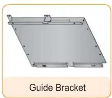
Metallic tray or bracket with mounting holes and a guide bracket label (no other text or symbols)
natural_image
Illustration of a power cable with coiled cable (no text or symbols on the diagram itself)

- Attention
• These illustrations may differ from your product and are subject to change.
- In some countries, a Y-type cable may be provided instead of the power cord.
- Always use genuine components to ensure safety and product life. Any damages or injuries by misuse or using an improper accessory are not covered by the warranty.
Optional Items
The following items are supported by the PC500-F***, but are not provided with the product. Please purchase optional items as needed.
- HDMI kit, HDMI cable, DP cable, LINE-OUT cable, LAN cable, mouse, keyboard.
Connections
Front Panel

Back Panel

| Number | Connection Description | |
| A | Power Cable In For the power cable. | |
| B | RS-232C Out For the RS-232C cable. | |
| C | Power Button Turns PC500-F*** on. | |
| D | LINE-OUT Connector For a LINE-OUT cable for analog audio transfer. | |
| E | USB In | For USB-type devices, including memory, hard disk, CD-ROM, keyboard, and mouse. |
| F | LAN Connector For a LAN cable. | |
| G | DP Output Port Connects the cable to the DP-supporting monitor. | |
| H | Monitor Docking Port Connects the PC500-F*** to a monitor. |
How to Install on Monitor
\*\*WS50, \*\*LT55A Models
We recommend you to use the items provided with your PC500-F*** and follow our instructions for integrating the product with your monitor in order to ensure the correct results.

Attention
- The illustrations shown are to guide your integration and may differ from your product.
1
Place a soft cloth on the table and put the product with the screen facing downward. Push the PC500-F*** into the compartment to mount it.

natural_image
Technical line drawing of a device interior with a magnified view of the internal structure (no text or symbols)2
Attach the PC500-F*** on the set using the four screws provided.


Attention
- Be careful of sharp edges on the rail and the handle.
- Fixing the product with non-standard screws may cause damage or the product to fall down. LG Electronics is not liable for any accidents relating to the use of non-standard screws.
- Do not over tighten the screws as this may cause damage to the product and void your warranty.
\*\*WX50MF Model
For proper use, it is recommended to use the basic components provided with the PC500-F*** to attach it to a monitor.

Attention
- The illustrations shown are to guide your integration and may differ from your product.
1
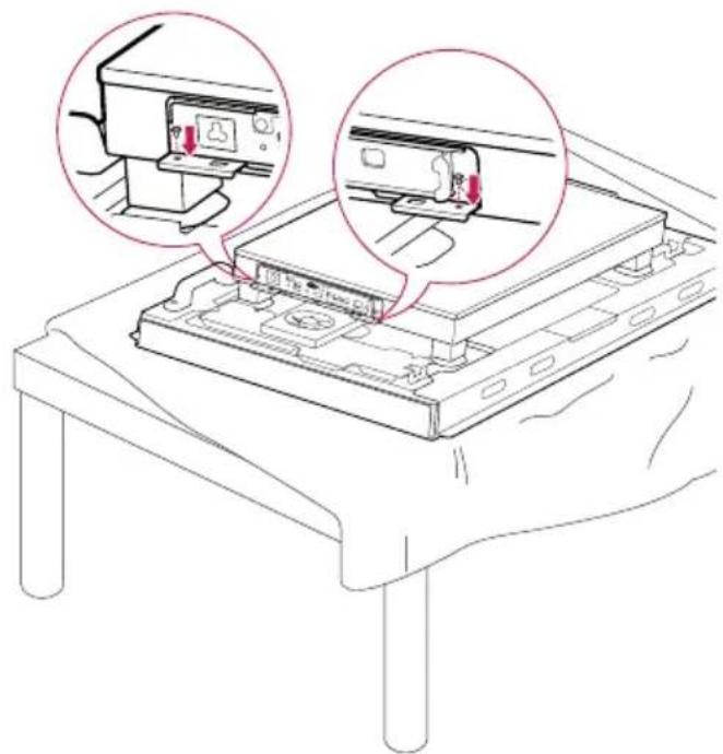
Place a soft cloth on the table and put the product with the screen facing downward. Remove the opening cover by unfastening two screws as shown in the picture.

natural_image
Technical line drawing of a mechanical assembly with two magnified views showing internal components (no text or symbols)2
Push the PC500-F*** into the compartment to mount it.

natural_image
Line drawing of an internal electronic device with a red arrow indicating a component (no text or symbols present)3
Attach the PC500-F*** on the product using the two screws provided.
natural_image
Line drawing of a computer monitor with two zoomed-in insets showing internal components (no text or symbols)
Attention
- Be careful of sharp edges on the rail and the handle.
- Attaching the product with non-standard screws may cause damage or the product to fall down. LG Electronics is not liable for any accidents relating to the use of non-standard screws.
- Do not over tighten the screws as this may cause damage to the product and void your warranty.
How to Install the Guide Bracket
1
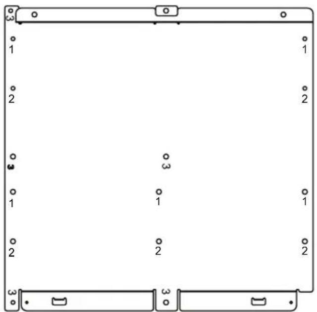
Make sure to match the numbers carved on the guide bracket and the numbers on the back cover when assembling the guide bracket.
2
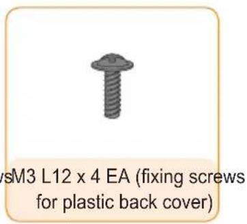
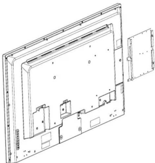
Attach the guide bracket to the back of your monitor. (3 or 4 screws are required depending on the model.)

natural_image
Top-down schematic of a computer monitor layout with ports, connectors, and a central display (no text or labels)(Model that requires 4 fixing screws for assembling the guide bracket>

natural_image
Technical line drawing of a mechanical or electronic component with no visible text, numbers, or symbols.(Model that requires 3 fixing screws for assembling the guide bracket>

natural_image
Technical line drawing of an open computer case with internal components and mounting hardware (no text or symbols)(Model that requires 4 fixing screws for assembling the guide bracket>
natural_image
Technical line drawing of a device casing with internal components and mounting holes (no text or symbols)3
Assemble the PC500-F*** to the guide bracket with the fixing screws.
(Model that requires 3 fixing screws for assembling the guide bracket>
Attach the PC500-F*** to the guide bracket with 4 fixing screws.

natural_image
Technical line drawing of a computer monitor case with visible internal components and mounting brackets (no text or symbols)(Model that requires 4 fixing screws for assembling the guide bracket>
Attach the PC500-F*** to the guide bracket with 4 fixing screws.
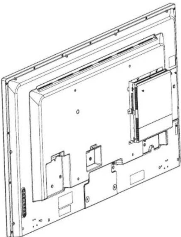
natural_image
Technical line drawing of a computer monitor rear panel showing internal components and mounting holes (no text or labels)In/Out Cable Connection
To view images on the monitor that is not connected to the monitor docking port of PC500-F*** , you need to connect the PC500-F*** to the monitor via a DP cable.

Attention
- HDMI kit, HDMI, DP, LINE-OUT, and LAN cables are not included in the basic components. You need to purchase a cable separately as it is not provided as an accessory.
- After cabling is complete, assign the SET ID of the monitor to be connected to PC500-F***.
- To configure the SET ID, please refer to the owner's manual for your monitor.

Note
When using the SuperSign Manager software:
- The monitor's SET ID is a unique number used to identify the monitor. You can choose a number from 1 to 25. The SET ID allows the SuperSign Manager software to identify the monitor.
- In order to directly connect the monitor to the PC500-F*** , its SET ID must be set to 1.
- To use SuperSign Manager, the monitor that will be connected to a PC500-F*** must support the LG RS232C protocol. A monitor supporting the LG RS232C protocol can be controlled the monitor functions, such as brightness and sound, using SuperSign Manager.
Connecting a Monitor with DP Cable

Attention
- To enable DP connection, the monitor that will be connected to PC500-F*** must support the DP input port.
- When connecting the DP (DisplayPort) cable, use the standard cable. Using a non-standard cable may cause a malfunction.
1 Connect the appropriate power cables to a monitor and PC500-F\*\*\* respectively.

2 Connect PC500-F\*\*\* to the monitor via a DP cable.

3 Connect PC500-F*** to the monitor (IN) with an RS-232C cable.
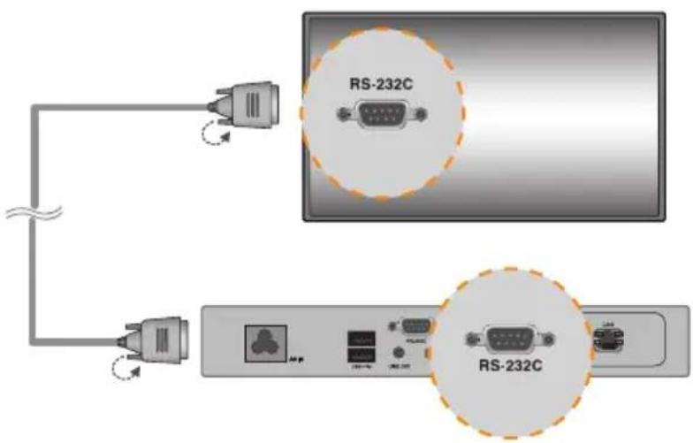
4 Connect a LAN cable to PC500-F***.


Attention
- When the product is turned on after cable connection or the operating system is completely booted, DP video output starts operating.
- The product does not support a dual mode where DP can be switched either to HDMI or DVI. It is only for DP output.
Connecting/Disconnecting DP Audio Device in Windows
Connecting/Disconnecting DP Audio Device in Windows Embedded Standard 7 P
1 Select Start > Control Panel > Hardware and Sound > Sound.
Click the Play tap first. Right-click on the Intel® Display Audio or 2 - Realtek High Definition Audio and select Set as Default Device, then click OK to connect the DP audio device or select Disable to disconnect it.
※ In order to change the audio devices, you may restart the computer.
Attention
- If an audio device is connected or removed while media content is played, you need to stop the content and play again.
- If a DP cable is removed from the PC500-F*** sound does not play. In addition, when the cable is reconnected, it may take time before sound plays again.
Connection to Multiple Monitors
Multiple monitors can be connected to a single PC500-F***. (The maximum number of monitors connected varies depending on the monitor type.) You can set the tile mode by connecting multiple monitors.
1 Connect the RS-232C Out port of the PC500-F*** to the RS-232C In port of the first monitor (SET ID 1).
2 Connect rest of the monitors using a RS-232C cable. (Be careful about input and output ports.)


Attention
- You may want to purchase additional RS-232C cables to use several monitors together.
- You cannot connect multiple monitors using a DP cable.
- Refer to the owner's manual of the monitor for the SET ID Max. value.

Attention
- Shut down the system properly using the Windows Start menu. Otherwise, this may cause errors such as data loss, which will lead damage to the product.
- Avoid using the product in a closed environment which could prevent the flow of the air. Otherwise, this may increase the product temperature, which will prevent it from operating normally and affect the product life.
- Using converting devices, such as DP to HDMI adapter and HDMI to DVI cable, may cause compatibility issues.
- When connecting the PC500-F*** into **WS50, **LT55A or **WX50MF through the monitor docking port, set the monitor input to SuperSign.
- When connecting/removing the PC500-F*** into/from the monitor through the monitor docking port, make sure to unplug the power cord connected to monitor and PC500-F*** respectively.
- The following monitors support the connection through the monitor docking port.
**WS50, **LT55A (LG Electronics)
**WX50MF (LG Electronics) - Disconnect the power cord first before moving or installing the product. Otherwise, this may result in electric shock.
- Make sure to reboot the PC500-F*** , when connecting the PC500-F*** through the monitor docking port and using the Factory Reset function.
- Using wireless devices may cause a malfunction.
Limitations of Microsoft Windows Embedded Standard
The following are potential errors that may occur due to internal limitations of Microsoft Windows Embedded Standard, which is the OS of Mini-PC for Signage.
- If you press Alt + Enter on the DOS window, text other than English may be shown corrupted.
- If you use Save As function in the Print window, the menu window name will be displayed in English.
- When you move to submenu items (such as in the Control Panel), some may appear in English. (e.g., HyperTerminal, Regional and Language Options, Device Manager)
Frequently Asked Questions (FAQs)
| Question Answer | |
| Where can I get a vaccine program? | This Mini PC comes packaged with the Windows program only. Please purchase a vaccine program separately for use. |
| The screen resolution is not adequate. | Check whether the screen resolution of Windows is set properly. |
| The edges of the image are cropped off. | For some models, you need to set the monitor input to PC mode. For more information, please refer to the owner's manual of your monitor. |
Unified Codecs
You need to install codecs required to play videos. Video files may require different codecs for playing. Websites to download unified codecs are listed below:
- http://www.codecguide.com
- http://shark007.net
- http://www.free-codecs.com

Note
- The websites above are not related to LG Electronics, and are subject to change.
- Visit their websites for details about the codec license.
- Make sure that a codec required to play the content you require is included in the download package before you install it.
- Avoid duplicate installations of a codec package.
- If you want to install a different code package, uninstall the previous codec first.
Network Setting
There are various network connection methods depending upon the specifications of your carrier or Internet service provider.

Attention
- Use a standard LAN cable (CAT5 or higher with a RJ45 connector). LG Electronics is not responsible for the Internet disconnection due to problems with or malfunctions of other connected devices. LG Electronics is not liable for any problems related to the Internet connection.

Make sure to read the Important Precautions before using the product.
Keep the User's Guide(CD) in an accessible place for furture reference.
The model and serial number of the SET is located on the back and one side of the SET.
Record it below should you ever need service.
MODEL
SERIAL
WARNING - This is a class A product. In a domestic environment this product may cause radio interference in which case the user may be required to take adequate measures.
Temporary noise is normal when powering ON or OFF this device.

- Mini-PC for Signage (Hardware)
- TABLE OF CONTENTS
- PC500-F\*\*\*
- Specifications 20
- Included in the Box 22
- Connections 23
- How to Install on Monitor 24
- How to Install the Guide Bracket ....26
- In/Out Cable Connection ....28
- Limitations of Microsoft Windows Embedded Standard .....35
- Frequently Asked Questions (FAQs) 35
- Attention
- Licenses
- Note
- Replacing Flash Memory Battery
- Specifications
- Included in the Box
- Basic Components
- Optional Items
- Connections
- How to Install on Monitor
- \*\*WS50, \*\*LT55A Models
- 1
- 2
- \*\*WX50MF Model
- 3
- In/Out Cable Connection
- When using the SuperSign Manager software:
- Connecting a Monitor with an HDMI Cable
- Connecting/Disconnecting HDMI Audio Device in Windows
- Connecting HDMI Audio Device
- Disconnecting HDMI Audio Device
- Connecting/Disconnecting HDMI Audio Device in Windows Embedded Standard 7 E,P
- Connecting a Monitor with DP Cable
- Connect the appropriate power cables to a monitor and PC500 respectively.
- Connect PC500 to the monitor via a DP cable.
- Connection to Multiple Monitors
- - Attention
- How to Install the Guide Bracket
- Connect the appropriate power cables to a monitor and PC500-F\*\*\* respectively.
- Connect PC500-F\*\*\* to the monitor via a DP cable.
- Connecting/Disconnecting DP Audio Device in Windows
- Connecting/Disconnecting DP Audio Device in Windows Embedded Standard 7 P
- Limitations of Microsoft Windows Embedded Standard
- Unified Codecs
- Network Setting
Brand : LG
Model : PC500-FDBFP
Category : Computer