
TPMS 2.1 - Tire pressure monitoring system BLAUPUNKT - Free user manual and instructions
Find the device manual for free TPMS 2.1 BLAUPUNKT in PDF.


| Product Type | Tire Pressure Monitoring System (TPMS) |
| Brand | Blaupunkt |
| Model | TPMS 2.1 (TPMS 2.1E / TPMS 2.1V) |
| Operating Frequency (Sensor) | 433.92 ± 0.05 MHz |
| Pressure Range (Sensor) | 0 – 8 Bar / 0 – 116 PSI |
| Temperature Range (External Sensor) | -30°C to 60°C |
| Temperature Range (Valve Sensor) | -40°C to 105°C |
| Battery Type (External Sensor) | CR1632 |
| Battery Voltage (Sensor) | 1.8 V – 3.3 V |
| Display Operating Current | < 20 mA |
| Display Charging Voltage | 5 V ± 0.5 V |
| Display Battery Capacity | 220 mAh |
| Display Operating Temperature | -30°C to 80°C |
| Pressure Display Range | 0 – 6.8 Bar / 0 – 99 PSI |
| Default High Pressure Threshold | 3.1 Bar / 45 PSI |
| Default Low Pressure Threshold | 1.8 Bar / 26 PSI |
| Default High Temperature Threshold | 80°C |
| Precision (Temperature) | ± 2°C |
| Precision (Pressure) | 0.1 Bar / 1.5 PSI |
| Power Supply (Display) | Solar panel + USB (5V) |
| Installation Type | Windshield mount with 3M tape |
| Alerts | High/low pressure, high temperature, sensor failure, battery low |
| Compliance | Not for sale in USA & Canada |
Frequently Asked Questions - TPMS 2.1 BLAUPUNKT
User questions about TPMS 2.1 BLAUPUNKT
0 question about this device. Answer the ones you know or ask your own.
Ask a new question about this device
Download the instructions for your Tire pressure monitoring system in PDF format for free! Find your manual TPMS 2.1 - BLAUPUNKT and take your electronic device back in hand. On this page are published all the documents necessary for the use of your device. TPMS 2.1 by BLAUPUNKT.
USER MANUAL TPMS 2.1 BLAUPUNKT
This TPMS (Tire Pressure Monitoring System) has been manufactured according to established safety guidelines. However, dangers may still occur if the safety notes in this manual is not observed. This manual is intended to familiarize the user with the TPMS's Important functions. Read this carefully, prior to using the appliance. Keep this manual in an easily accessible location. In addition, do observe the instructions of the devices used in conjunction with this appliance.
Road Safety
Always observe the following notes for road safety: - Device must be used in a way that compliments the safety of the user when driving the vehicle. It is recommended for the user to park at an appropriate location when examining the tires in case of abnormal alert.
General Safety
- Device is intended for installation and operation in a vehicle with 12V vehicle system outage, hence the device must be installed 500mm away from the DVD or high power equipment to prevent signal disruption.
- Do not dismantle or modify the device. Installation or repair should be performed by a specialist. Blaupunkt is not liable for any loss or damage resulting from unauthorized disassembly or modification to the device.
- Device is designed to monitor tire pressure and temperature only. Driver is responsible for the upkeep of the tires.
- Blaupunkt is not liable in case of loss of sensors. Contact your Blaupunkt dealer to purchase new sensors.
- Package comes with pre-set sensor for designated tires. In case of sensor replacement or change of sensor location, ensure the sensor are reprogrammed before operating.
-
Please do not operate the device under such conditions (extremely high temperature or extremely low temperature); ensure that the temperature within the car ranges from -30°C to 80°C before you begin installation process and during operation.
-
For continuous usage, ensure TPMS display is charged at least 1 time a week or when used for more than 4 hours per day.
- For abnormalities, please refer to the "Trouble shooting" section. Consult with Blaupunkt dealer for further examining, in case if the problem cannot be resolved.
This manual may be updated from time to time without any notice.
Disclaimer
In no event shall Blaupunkt be liable for any direct, indirect, punitive, incidental, special consequential damages to property or life and whatsoever arising out of or connected with the use or misuse of our products. USA & CANADA: This product is not intended for sale in the United States and Canada. If purchased in the U.S. or Canada, this product is purchased on as-is basis. No warranty, whether expressed or implied is provided in the U.S. or Canada.
STRUCTURE & FUNCTIONS
Display
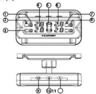
External Sensor Valve Sensor
Functions
Display
- Sensor Battery Status
- High Temperature Warning
- Tire Temperature Value
- Right Button
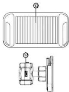
- Solar Panel
-
USB Charging Port
-
Pressure Unit
-
TPMS Alarm Icon
-
Temperature Unit
-
Solar Power
-
Display Battery Status
-
Power/ Left Button
-
Setting Button
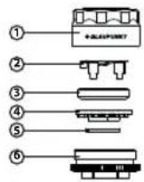
External Sensor
-
Sensor Cover
-
Battery Holder
-
Battery
-
Sensor
-
Rubber Seal
-
Base
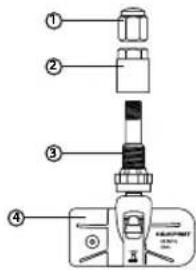
Valve Sensor
-
Dust Cap
-
Aluminium Alloy Nut
-
Aluminium Alloy Valve
-
Transmitter
SPECIFICATIONS
Sensor
Operating frequency 433.92 ± 0.05MHz
Battery voltage 1.8V \~ 3.3V
Operating temperature -30°C \~ 60°C (External Sensor)
-40°C \~ 105°C (Valve Sensor)
Pressure range 0\~8 Bar / 0\~116 PSI
Battery Model CR1632 (External Sensor)
Display
Operating current <20mA
Operating frequency 433.92+0.05MHz
Charging voltage 5V±0.5V
Operating temperature -30°C - 80°C
Pressure display range 0-6.8Bar/0-99PSI
Battery Capacity 220mAh
Default Value
High pressure value 3.1 Bar / 45 PSI
Low pressure value 1.8 Bar / 26 PSI
High temperature value 80°C
Precision
Temperature +/-2°C
Pressure 0.1 Bar / 1.5 PSI
Temperature unit 1°C = 33.8°F = 274.15 K
Air pressure unit 1 Bar = 14.5 PSI = 100 Kpa = 1.02Kgf/cm²
Accessories
Display
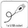
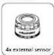
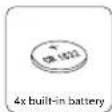
TPMS 2.1E
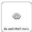
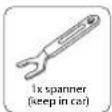
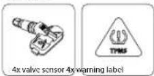
TPMS 2.1V
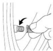
EXTERNAL SENSOR INSTALLATION
- Remove the valve cap.
natural_image
Hand holding a small mechanical component with an arrow indicating direction (no text or symbols)-
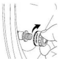
Screw in the nut.
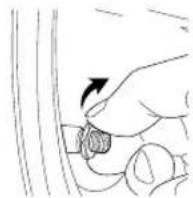
-
Screw on the sensor.
natural_image
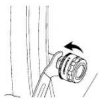
Hand holding a screwdriver with an arrow indicating rotation (no text or symbols)- Tighten up the nut to the sensor by using the spanner.
natural_image
Simple line drawing of a hand holding a cylindrical object with an arrow indicating rotation (no text or symbols)-
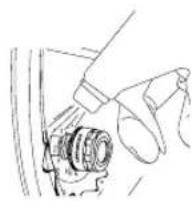
Spray soap water on the nozzle to check for leakage problem.
-
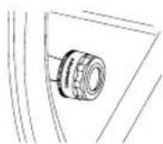
Clean the area before using it.
EXTERNAL SENSOR BATTERY REPLACEMENT
- Unscrew the nut.
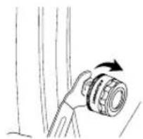
natural_image
Simple line drawing of a cable being inserted into a spring (no text or symbols)- Unscrew the sensor.
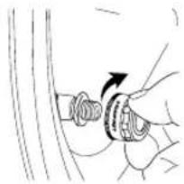
natural_image
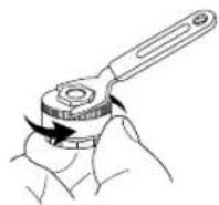
Hand holding a mechanical component with an arrow indicating rotation (no text or symbols)- Unscrew the sensor cover by using spanner.
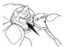
- Replace new battery.
- Refer to "Sensor Installation" steps.

natural_image
Pure technical line drawing of a mechanical component without any text, numbers, or symbolsVALVE SENSOR INSTALLATION
- Remove the original air valve from the wheel barrel.
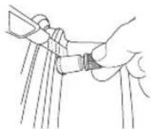
- Install & adjust the valve sensor onto the wheel barrel. Screw & tighten the nut & valve.
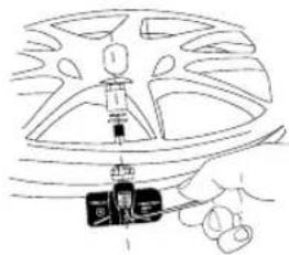
natural_image
Line drawing of a car wheel with a hand holding a small object (no text or symbols)- Inflate the tire after installation.
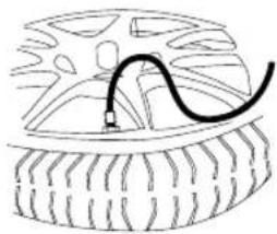
natural_image
Diagram of a car tire with a curved cable inserted into the center (no text or symbols)- Rebalance the wheel to ensure radial uniformity.
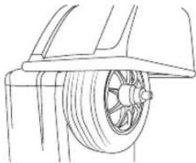
natural_image
Technical line drawing of a car wheel assembly (no text or symbols)- Reinstall the balanced wheel onto the vehicle.
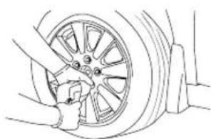
natural_image
Line drawing of a car tire being adjusted for a wheel, showing the wheel rim and tire (no text or symbols)DISPLAY INSTALLATION
Remove the 3M tape protective film to affix the display on the windscreen.1.
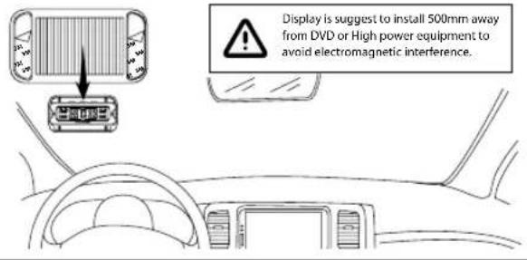
- The display supports solar power & USB charging mode. (Note: Charge the display with USB cable up to 4 hours before using for the first time and connect the USB cable to the display at overcast and rainy day.)
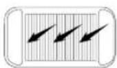
a) Solar Power
• Display will be charged automatically as long as the solar panel is facing sunlight.
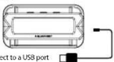
b) USB
- Connect USB charger to the power supply input of the display.

TROUBLESHOOTING
If any of the following problem occur, please resort to Troubleshooting for the possible solutions. Consult Blaupunkt authorized dealer if problem persist.
| Problems | Solutions |
| Air leakage after sensor installation | The tire valves may not be universal standard, please check with the local workshop. |
| No tire data are displayed after completing installation | Ensure the USB cable is connected to the display & charging up to 4 hours before using for the first time. |
| Missing or lost sensor | Please purchase new sensor. |
| External sensor battery low | Please replace with battery CR1632. |
| Change of tire location | Please reprogram the corresponding sensors. |
DIFFERENT SCENARIO
Front Left (FL)
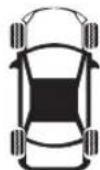
Front Right (FR)
Rear Left (RL)
Rear Right (RR)
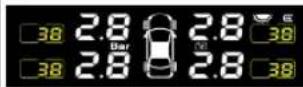
- Normal
Displays real time tire pressure & temperature of 4 tires.
- High Pressure
Di-Di-Di-Di-Di-
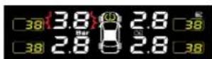
- Air Leakage
Di-Di-Di-Di-Di
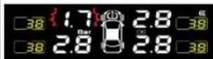
- High Temperature
Di-Di-Di-Di-Di-
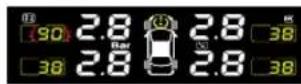
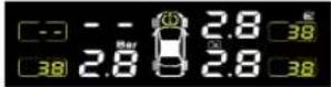
- Sensor Failure
- Low Battery a) Display
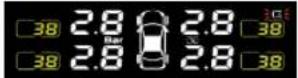
b) Sensor
• Di- Di- Di- Di- Di-
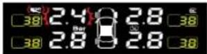
SETTING SETTING
1. Unit Switching
a) Press & hold button "M to enter setting interface.
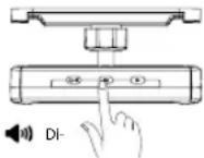
b) After entering the setting interface, P1, Pressure units (Bar /PSI) & temperature units (°C /°F) will flash.
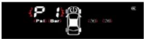
c) Press button "M" for unit setting, press the button "▶" to switching pressure & temperature unit. Press button "M" again to confirm the preferred units. Press button "◀" to exit setting interface.
2. Threshold Value Setting
a) Press & hold button "M" to enter setting interface.
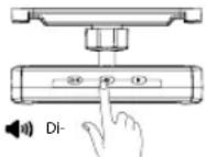
b) Press button "▶", P2, Left Front tire icon will flash.
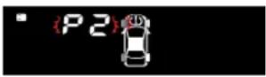
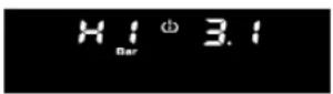
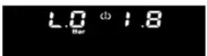
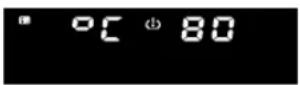
c) Press button "M" then press the button "▶" to switch between threshold value interface (High Pressure Value, Low Pressure Value & High Temperature Value). Select the preferred interface by pressing button "M". The digit will flash then press the button "▶" to adjust the preferred value & press "M" to confirm.
• High Pressure Value Setting Interface
• Low Pressure Value Setting Interface
- High Temperature Value Setting Interface
d) Press button " ⏻◀" to exit setting interface.
- Tire Position Exchange Setting (It is required only when the tires has switched location)
a) Press & hold button "M" to enter setting interface.
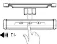
b) Press button "▶" twice, P3 will flash.
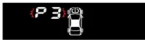
c) Press button "M", the digits on the top left & top right will flash.
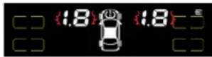
d) Press the button "▶" to switch preferred position, press button "M" to select. Press button "◀" to exit setting interface.
4. Sensor Pairing Setting
(It is required only when the sensors has switched location or be replaced)
a) Press & hold button "M" to enter setting interface.
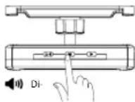
b) Press button "▶" thrice, P4 will flash.

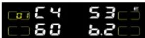
c) Press button "M" to enter pairing mode. The old sensor ID of front left will be shown on the display.
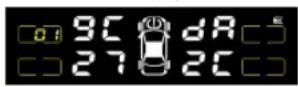
d) Press the button "▶" to switch the preferred position (sensor ID of the corresponding tire position will be displayed), press button "M" to select. (Pairing order: Front Left > Front Right > Rear Right > Rear Left)
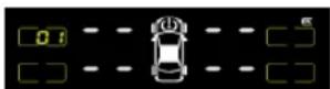

- Ensure that there is only one of the tire with sensor is activated during pairing, otherwise there is no guarantee that the sensor ID that really needs to be paired will be paired into the receiver. - To cancel the current pairing process by pressing return key, however pairing process cannot be canceled after pairing process is successful.
- Disassemble the external sensor from the front left tire & reinstalled, for sensor ID pairing activation.
- Valve sensor - Releasing the air from tire continuously instead of intermittently, ensure that the releasing process is not less than 8 second. - Do not exceed the maximum pressure of tire during inflating.
f) When system receives the signal, you will hear "Di-" which indicates successful sensor pairing (new sensor ID will be displayed). Then, it will continue to next order. Press button "∅◀" to exit setting interface.
Designed and engineered by Blaupunkt Competence Centre
TPMS 2.1E
1 311 21 006 45 01
TPMS 2.1V
1 311 21 007 45 01
- Road Safety
- General Safety
- Disclaimer
- STRUCTURE & FUNCTIONS
- Functions
- Display
- External Sensor
- Valve Sensor
- SPECIFICATIONS
- Sensor
- Default Value
- Precision
- Accessories
- EXTERNAL SENSOR INSTALLATION
- EXTERNAL SENSOR BATTERY REPLACEMENT
- VALVE SENSOR INSTALLATION
- DISPLAY INSTALLATION
- TROUBLESHOOTING
- DIFFERENT SCENARIO
- SETTING SETTING
- Unit Switching
- Threshold Value Setting
- Sensor Pairing Setting
Brand : BLAUPUNKT
Model : TPMS 2.1
Category : Tire pressure monitoring system