
DVI DA2 - Hi-Fi System Extron - Free user manual and instructions
Find the device manual for free DVI DA2 Extron in PDF.


| Product Type | DVI Distribution Amplifier |
| Brand | Extron |
| Model | DVI DA2 |
| Input | 1 x DVI-D (single link) |
| Outputs | 2 x DVI-D (single link) |
| Maximum Resolution | 1920x1200 @ 60 Hz or 1080p |
| Video Bandwidth | 165 MHz |
| Dimensions (H x W x D) | 1.7 in (4.3 cm) x 4.3 in (10.9 cm) x 1.0 in (2.5 cm) |
| Weight | 0.5 lbs (0.23 kg) |
| Power Supply | External, 5V DC, 1A |
| Power Consumption | 2.5 watts (max) |
| Enclosure | Metal, black |
| Mounting | Desk-top or optional rack shelf |
| Supported Formats | DVI single link, HDMI via adapter (DVI to HDMI) |
| EDID Management | Automatic EDID pass-through |
| Temperature Range | 32 to 122 °F (0 to 50 °C) |
| Humidity | 10% to 90% non-condensing |
| Maintenance | Clean with dry cloth; no lubrication required |
| Safety | Use only supplied power adapter; disconnect when not in use |
| Spare Parts | Contact Extron customer support |
| Repairability | No user-serviceable parts inside; refer to qualified service |
Frequently Asked Questions - DVI DA2 Extron
User questions about DVI DA2 Extron
0 question about this device. Answer the ones you know or ask your own.
Ask a new question about this device
Download the instructions for your Hi-Fi System in PDF format for free! Find your manual DVI DA2 - Extron and take your electronic device back in hand. On this page are published all the documents necessary for the use of your device. DVI DA2 by Extron.
USER MANUAL DVI DA2 Extron
DVI DA2 and DVI DA 4 • User Guide
This guide describes the installation and operation of the Extron DVI DA2 and DVI DA4 Distribution Amplifiers. Unless stated otherwise, "distribution amplifier" or "the unit" in this guide refer to both models.
FCC Class A Notice
This equipment has been tested and found to comply with the limits for a Class A digital device, pursuant to part 15 of the FCC rules. The Class A limits provide reasonable protection against harmful interference when the equipment is operated in a commercial environment. This equipment generates, uses, and can radiate radio frequency energy and, if not installed and used in accordance with the instruction manual, may cause harmful interference to radio communications. Operation of this equipment in a residential area is likely to cause interference. This interference must be corrected at the expense of the user.
NOTE: For more information on safety guidelines, regulatory compliances, EMI/EMF compatibility, accessibility, and related topics, see the "Extron Safety and Regulatory Compliance Guide" on the Extron website.
Specifications Availability
Product specifications are available on the Extron website, www.extron.com.
About the DVI DA2 and DVI DA4
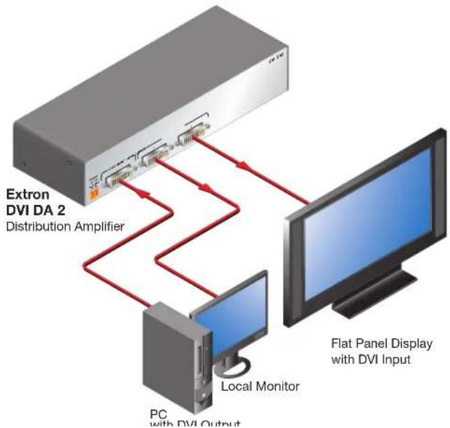
The Digital Visual Interface (DVI) Distribution Amplifiers (DAs) have one input and either two (DVI DA2) or four (DVI DA4) outputs. Output 1 for each model is for a local monitor and is used for Digital Display Channel (DDC) reference.
Both distribution amplifiers accept one single link DVI-D input and drive two (DVI DA2) or four (DVI DA4) single link DVI-D output signals.
flowchart
graph TD
    A["Extron DVI DA 2\nDistribution Amplifier"] --> B["PC with DVI Output"]
    B --> C["Local Monitor"]
    C --> D["Flat Panel Display with DVI Input"]
Figure 1. DVI DA2 Application Diagram
DVI DA2 and DVI DA4 Features
- External power supply — The DVI DA2 and DVI DA4 are powered by an external 12 VDC power supply (provided with the units).
- DVI-D input — Both distribution amplifiers accept one single link DVI-D input with a range of resolutions up to 1920 x 1200 or 1080p @ 60 Hz.
- Input equalization — Input Equalization (EQ) conditions the input signals to ensure the integrity of the signals delivered to the output devices.
• DVI-D outputs — The units drive two (DVI DA2) or four (DVI DA4) single link DVI-D output signals.
- DDC routing to the local monitor — Output 1 is used as a DDC reference and is labeled "Local Monitor" for easy reference. The video source uses the bidirectional DDC to communicate with the local monitor, which allows the source to determine the resolution and refresh rate of the signal that it sends.
NOTES:
- Since output 1 is used as the reference, all other display devices must be capable of handling resolutions equal to or greater than that of the local monitor.
- The actual signal transmission distance can vary greatly and depends on signal resolution, cable type, cable quality, graphics card, and the display used in the system.
- Versatile mounting options — Both units are 1U high, 3 inches (7.62 cm) deep, and 1/2 rack (8.7 inches or 22.1 cm) wide, allowing them to be conveniently mounted in a rack, mounted under a desk, or set on a tabletop.
Installation Overview
Both distribution amplifiers can be placed on tabletops, or mounted under furniture or in racks by following these steps:
- Turn off all electrical equipment. Make sure that the input sources, the DA and the output display(s) are all turned off and all power sources and signal cables are disconnected.
- Mount the unit (see Mounting page 5).
- Connect the cables (see DVI Connections on page 3).
- Plug in the power supply (see page 3), then turn on the display devices and input devices.
Front Panel Features
The front panels of the DVI DA2 and DVI DA4 are identical and shown in the illustration below
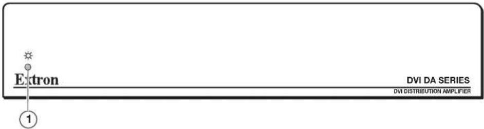
Figure 2. DVI DA2 and DVI DA4 Front Panel (both models are identical)
① LED indicator — On both the DVI DA2 and DVI DA4, the LED indicator lights when the unit is receiving power.
Rear Panel Features
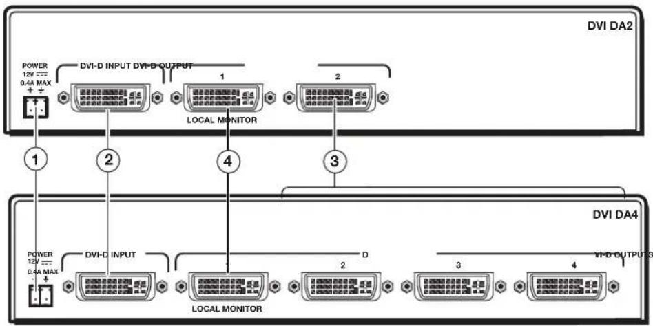
Figure 3. DVI DA2 (top) and DVI DA4 (bottom) Rear Panels
① Power input
② Input connector
③ Output connector
④ Local Monitor connector
① Power input — Connect the provided power supply to the 3.5 mm, captive screw power receptacle.
NOTES:
- The length of the exposed wires in the stripping process is critical. The ideal length is 3/16 inch (5 mm).
- If the exposed section is longer, the exposed wires may touch, causing a short circuit between them.
- If it is shorter, the wires can be easily pulled out, even if tightly fastened by the captive screws.
- Do not tin the wires. Tinned wire does not hold its shape and can become loose over time.
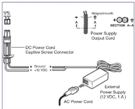
Figure 4. Power Connection
ATTENTION:
- This product is intended to be supplied by a Listed Power Unit marked “Class 2” or “LPS,” rated 12 VDC, maximum 1.0 A. Always use a power supply supplied or specified by Extron. Use of an unauthorized power supply voids all regulatory compliance certification and may cause damage to the supply and the end product.
- Unless otherwise stated, the AC/DC adapters are not suitable for use in air handling spaces or in wall cavities. The power supply is to be located within the same vicinity as the Extron AV processing equipment in an ordinary location, Pollution Degree 2, secured to the equipment rack within the dedicated closet, podium, or desk.
- The installation must always be in accordance with the applicable provisions of National Electrical Code ANSI/NFPA 70, article 75, and the Canadian Electrical Code part 1, section 16. The power supply shall not be permanently fixed to building structure or similar structure.
DVI Connections
② Input connector — Connect the input signal to the female DVI connector. The DVI input signal is equalized to ensure integrity.
③ Output connectors — Connect up to two (DVI DA2) or four (DVI DA4) DVI-D outputs to display devices, using the female DVI connectors.
NOTE: The outputs are not HDCP compatible.
④ Local Monitor connector — Output 1 (Local Monitor) is used as a Hotplug Detect, a DDC clock, and a DDC data reference. For the input device to provide a signal at the correct resolution and refresh rate, there must be a display device connected to output 1.
NOTE: Although the source device, local monitor, and remote display devices all connect to the distribution amplifiers through DVI-I connectors, the DVI DA2 and DVI DA4 are compatible only with single-link DVI-D video signals.
To enable the units to accept sources providing HDMI signals or to provide signals to displays that accept HDMI signals, use a HDMI to DVI adapter or cable, such as the Extron HDMIF-DVIDM female HDMI to male DVI-D adapter or the Extron HDMI M-DVI-D M series of male HDMI to male DVI cables.
The input signal is one single link DVI-D with a resolution range up to 1920x1200 or 1080p @ 60 Hz.
Input EQ conditions input signals to ensure the integrity of the signals delivered to the output devices.
NOTES:
- The actual signal transmission distance can vary and depends on the signal resolution, cable quality, graphics card, and display used in the system.
- To ensure proper operation, display devices connected to outputs 2 through 4 must be able to handle resolutions equal or greater than that of the local monitor on output 1.
DVI Connector Pin Assignments
The illustration below shows the pin assignments for the male and female DVI-I connectors.
NOTE: Although DVI-I dual link connectors are used, the DVI DA2 and DVI DA4 are compatible only with single-link DVI-D video signals.
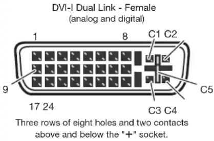 | Pin | Signal | Pin | Signal | Pin | Signal |
| 1 TMDS data 2-9 TMDS data 1-17 TMDS data 0- | ||||||
| 2 TMDS data 2+10 TMDS data 1+18 TMDS data 0+ | ||||||
| 3 TMDS data 2/4 shield | 11 TMDS data 1/3 shield | 19 TMDS data 0/5 shield | ||||
| 4 TMDS data 4-12 TMDS data 3-20 TMDS data 5- | ||||||
| 5 TMDS data 4+13 TMDS data 3+21 TMDS data 5+ | ||||||
| 6 DDC clock 14 +5V power 22 TMDS clock shield | ||||||
| 7 DDC data 15 Ground 23 TMDS clock+ | ||||||
| 8 Analog vertical sync 16 Hot plug detect 24 TMDS clock | ||||||
| C1 Unused | C3 Unused | C5 Unused | ||||
| C2 Unused | C4 Unused | |||||
Operation
To operate the unit (see figure 3 on page 2 and figure 4 on page 3):
- Connect the power supply.
- Connect and power on the Local Monitor.
- Connect and power on any other output displays.
- Connect and power on the source device.
NOTE: Output 1 (Local Monitor) is used as a DDC reference and must be connected to the distribution amplifier before the source device is powered on. If the source device cannot communicate with the local monitor when it is being powered on, it may not be able to send a video signal or the signal may have the wrong resolution or refresh rate.
If there are any problems, consult the Troubleshooting section below.
Troubleshooting
- No output signal — Check that the front panel LED is lit. If it is not, check the power supply connections to the unit (see page 4).
- No output signal or poor quality signal — Check the integrity of the cabling to output 1 (Local Monitor) and ensure that output 1 is connected to the distribution amplifier before powering on the source device.
If the source device cannot communicate with output 1 when it is being powered on, it may not be able to send a video signal or the signal may have the wrong resolution or refresh rate.
- No output signal or poor quality signal — Check the input and output cabling (page 3). DVI signals run at very high frequency and poor connections can cause degradation or loss of the signal, or jitter. To avoid this:
• Use only cable that is designed for DVI signals.
- Limit or avoid the use of adapters.
- Display device shows a flashing black or blue screen, snow or other distortion — A device that is not HDCP compliant may be receiving HDCP-encrypted signals.
The DVI DA2 and DVI DA4 are not High-Bandwidth Digital Content Protection (HDCP) compliant. They will pass HDCP-encrypted signals only to the local output device.
- Signal on local monitor but not on other displays — Check that all output devices (monitors or projectors) can handle resolutions equal to or greater than that of the local monitor.
Mounting
Attach the four provided rubber feet to the bottom of the unit and place it in any convenient location.
Rack Mounting
UL Guidelines for Rack Mounting
The following Underwriters Laboratories (UL) guidelines are relevant to the safe installation of these products in a rack:
- Elevated operating ambient temperature — If the unit is installed in a closed or multi-unit rack assembly, the operating ambient temperature of the rack environment may be greater than room ambient temperature. Therefore, install the equipment in an environment compatible with the maximum ambient temperature (Tma: +122 °F, +50 °C) specified by Extron.
- Reduced air flow — Install the equipment in the rack so that the equipment gets adequate air flow for safe operation.
- Mechanical loading — Mount the equipment in the rack so that uneven mechanical loading does not create a hazardous condition.
- Circuit overloading — Connect the equipment to the supply circuit and consider the effect that circuit overloading might have on overcurrent protection and supply wiring. Consider the equipment nameplate ratings when addressing this concern.
- Reliable earthing (grounding) — Maintain reliable grounding of rack-mounted equipment. Pay particular attention to supply connections other than direct connections to the branch circuit (such as the use of power strips).
Rack Mounting Procedure
The unit can be mounted on any rack systems. To mount the product on a rack shelf, follow the instructions provided with the shelf accessories.
68-1376-01
Rev. G
10 13
| Extron Headquarters+800.633.9876 Inside USA or Canada OnlyExtron USA - West Extron USA - East+1.714.491.1500 +1.919.850.1000+1.714.491.1517 FAX +1.919.850.1001 FAX | Extron Europe+800.3987.6673Inside Europe Only+31.33.453.4040+31.33.453.4050 FAX | Extron Asia+65.6383.4400+65.6383.4664 FAX | Extron Japan+81.3.3511.7655+81.3.3511.7656 FAX | Extron China+86.21.3760.1568+86.21.3760.1566 FAX | Extron Middle East+971.4.299.1800+971.4.299.1880 FAX | Extron Korea+82.2.3444.1571+82.2.3444.1575 FAX | Extron India1800.3070.3777(Inside India Only)+91.80.3055.3777+91.80.3055.3737 FAX |
- DVI DA2 and DVI DA 4 • User Guide
- FCC Class A Notice
- Specifications Availability
- About the DVI DA2 and DVI DA4
- DVI DA2 and DVI DA4 Features
- NOTES:
- Installation Overview
- Front Panel Features
- Rear Panel Features
- ATTENTION:
- DVI Connections
- DVI Connector Pin Assignments
- Operation
- Troubleshooting
- Mounting
- Rack Mounting
- UL Guidelines for Rack Mounting
- Rack Mounting Procedure
Brand : Extron
Model : DVI DA2
Category : Hi-Fi System