
DEZ06T10 - Security Camera Digimerge - Free user manual and instructions
Find the device manual for free DEZ06T10 Digimerge in PDF.


| Product Type | Security Camera |
| Brand | Digimerge |
| Model | DEZ06T10 |
| Image Sensor | 1/2.7-inch CMOS |
| Resolution | 1920 x 1080 (Full HD) |
| Lens | 2.8mm fixed |
| Night Vision | Up to 30m with IR LEDs |
| Field of View | 90° diagonal |
| Power Supply | 12V DC / PoE (802.3af) |
| Power Consumption | Max 6W |
| Dimensions (WxHxD) | 70mm x 60mm x 140mm |
| Weight | 210g |
| Weatherproof Rating | IP66 |
| Operating Temperature | -30°C to 60°C |
| Video Compression | H.265 / H.264 |
| Motion Detection | Yes, adjustable sensitivity |
| Audio | Built-in microphone (optional) |
| Mounting | Wall or ceiling mount included |
| Maintenance | Clean lens with soft, dry cloth; check connections periodically |
| Safety Precautions | Disconnect power before installation; avoid exposure to extreme temperatures |
Frequently Asked Questions - DEZ06T10 Digimerge
User questions about DEZ06T10 Digimerge
0 question about this device. Answer the ones you know or ask your own.
Ask a new question about this device
Download the instructions for your Security Camera in PDF format for free! Find your manual DEZ06T10 - Digimerge and take your electronic device back in hand. On this page are published all the documents necessary for the use of your device. DEZ06T10 by Digimerge.
USER MANUAL DEZ06T10 Digimerge
DIG!MERGE | Right for Business
DEZ06T10
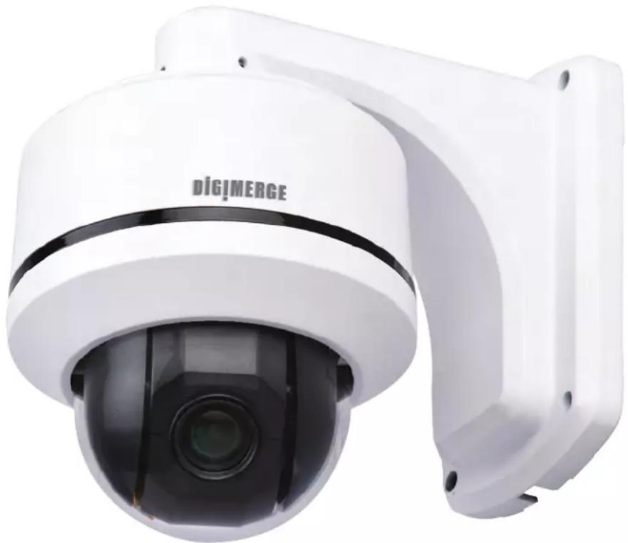
TDN Mini Outdoor 10X PTZ Camera
natural_image
White DigiMERGE security camera with mounted sensor array (no visible text or symbols on body)Instruction Manual
English Version 1.0
www.digimerge.com
Copyright © 2012 Digimerge Technologies Inc.
Thank you for purchasing the Digimerge 10X PTZ Speed-Dome Camera.
This manual refers to the following models:
- DEZ06T10
For the latest online manual and to learn about our complete range of accessory products, please visit our website at:
www.digimerge.com

CAUTION
RISK OF ELECTRIC SHOCK DO NOT OPEN DURING OPERATION

CAUTION: NO USER SERVICABLE PARTS INSIDE. REFER SERVICING TO QUALIFIED SERVICE PERSONNEL.

The lightning flash with arrowhead symbol, within an equilateral triangle, is intended to alert the user to the presence of uninsulated "dangerous voltage" within the products' enclosure that may be of sufficient magnitude to constitute a risk of electric shock.

The exclamation point within an equilateral triangle is intended to alert the user to the presence of important operating and maintenance (servicing) instructions in the literature accompanying the appliance.
CAUTION: TO PREVENT ELECTRIC SHOCK, MATCH WIDE BLADE OF THE PLUG TO THE WIDE SLOT AND FULLY INSERT.
Features
• 1/3" Sony EX-View™ II 960H, 700+ TVL
• 10x Optical/10x Digital Zoom
- Polaris Vision low light viewing
- True Day/Night with IR Cut Filter (TDN)
• High-Speed 360°/sec max. Pan/Tilt
- 360^ continuous rotation
- Advanced Digital Noise Reduction (DNR)
• 127 Preset positions, 8 patterns & tours
• Supports Pelco D/P protocols
- Wall mount bracket pre-attached for quick outdoor installation
- Removable base for easy surface/flush-mount installation
- OSD menu control
- IP66 weatherproof rated with included wall mount
- 12V DC operation
As our products are subject to continuous improvement, Digimerge reserves the right to modify product design, specifications and prices, without notice and without incurring any obligation. E&OE
Safety Instructions
- Read this guide carefully and keep it for future reference.
- Follow all instructions for safe use of the product and handle with care.
- Camera is rated for outdoor use and is weatherproof using the included wall mount or accessory ceiling mount only. For indoor installations, camera may be directly attached to a ceiling or flush mounted.
- Camera is not intended for submersion in water. Installation under a sheltered environment is recommended.
- Use the camera within given temperature, humidity, and voltage levels noted in the Technical Specifications.
- Do not disassemble the camera.
- Do not point the camera directly towards the sun or a source of intense light.
- Make sure to install the camera in a location that can support the camera weight.
- Make sure there are no live electrical cables in the area where you plan to mount the camera.
- Periodic cleaning may be required. Use a damp cloth only. Do not use anything other than water to clean the dome cover, as chemicals such as acetone can permanently damage the plastic.
TABLE OF CONTENTS
1. Getting Started .... 1
1.1 Optional Accessories 1
2. Connecting the Camera 2
2.1 Default Protocol Information 2
2.2 Power Requirements 2
2.3 RS485 Connection 3
2.4 Alarm Input Connection 3
3. Changing Protocol Information .... 5
3.1 Accessing the DIP Switches 6
3.2 Setting the Camera ID 6
3.3 Setting the Camera Protocol and Baud Rate 8
4. Installation 9
4.1 Installation Warnings 9
4.2 Wall Mount Installation (Indoor/Outdoor) 9
4.3 Ceiling Mounting (Indoor Only) 11
4.4 Flush Mounting (Indoor Only) 15
5. Using the OSD Menu....18
5.1 Operating the Main Menu 18
5.2 Display Setup 19
5.2.1 Set North Direction ..... 20
5.3 Camera Setup 20
5.3.1 Camera Setup 20
5.3.2 Motion Setup 23
5.3.3 Preset Setup 25
5.3.4 Swing Setup 27
5.3.5 Pattern Setup 28
5.3.6 Group Setup 29
5.4 System Initialize 31
5.5 Reserved Keyboard Shortcuts 32
6. Technical Specifications .... 33
7. Dimensions .... 34
8. Troubleshooting 35
1. GETTING STARTED
Before you start, ensure you have received all the items listed below:

natural_image
Line drawing of a surveillance camera with mounted lens and wall-mounted frame (no text or symbols)Camera and Wall Mount

natural_image
Four identical line drawings of a screw or plastic component, shown in different angles (no text or symbols)Wall Mount Screws

natural_image
Simple geometric diagram of a circle with a smaller circle at center and four evenly spaced dots on the perimeter (no text or symbols)Foam Pad

natural_image
Four identical mechanical fasteners with threaded ends, shown in line drawing style (no text or symbols)Ceiling/Flush Mount Screws
Instruction Manual
1.1 OPTIONAL ACCESSORIES
Contact your distributor for details.
natural_image
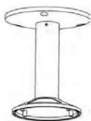
Simple line drawing of a cylindrical object with a flange and base (no text or symbols)MNTV0XC Ceiling Mount

natural_image
Line drawing of a handheld electronic device with a control knob and keypad (no text or symbols)ACCKBD120 PTZ Controller
2. CONNECTING THE CAMERA

flowchart
graph TD
    A["Monitor"] -->|BNC| B["RS485"]
    C["Controller/DVR"] -->|12V DC| B
    D["Power"] -->|12V DC| B
    B --> E["Video Cable (6-pin)"]
    B --> F["Alarm Cable (5-pin)"]
    G["IrDA Sensor"] --> H["Door Switch"]
    I["Sensor"] --> H
NOTE: Video and Alarm Cable are pre-attached to the camera.
2.1 DEFAULT PROTOCOL INFORMATION
- Default ID: 1
- Default Baud Rate: 2400
- Default Protocol: Pelco-D
If you need to change the PTZ protocol information, see “Changing Protocol Information” on page 5.
2.2 POWER REQUIREMENTS
This high voltage PTZ camera uses 12V DC power only.
• Max Power Consumption: 850 mA / 7.2W.
2.3 RS485 CONNECTION
For PTZ control, connect this line to keyboard controller or DVR. To control multiple cameras at the same time, RS-485 communication lines are connected in parallel as shown below.

2.4 ALARM INPUT CONNECTION

Before connecting sensors, check driving voltage and output signal type of the sensor. Since output signal types of the sensors are divided into Open Collector and Voltage Output types in general, the cabling must be
done properly after considering these types.
| Signal | Description |
| IN COM+ | Connect (+) cable of electric power source for Sensors to this port as shown in the circuit on previous page. |
| IN1-,IN2-,IN3-,IN4- | Connect output of sensors for each port as shown in the circuit on previous page. |
If you want to use Alarm Input, the types of sensor must be selected in the OSD menu (see “Alarm Input Setup” on page 24). The sensor types are Normal Open and Normal Close. If sensor type is not selected properly, the alarm can be activated reversely.
| Normal Open (N.O) | Output Voltage is high state when sensor is activated |
| Normal Close (N.C) | Output Voltage is low state when sensor is activated |
3. CHANGING PROTOCOL INFORMATION
The DIP switches on the bottom of the camera control 3 values:
- The ID of the camera, which allows the DVR/keyboard controller to identify different PTZ cameras.
- The protocol, which is the language that allows the camera and DVR/keyboard controller to speak to each other (e.g. Pelco D).
- The baud rate, which is the frequency of communications.
The illustration below shows the default values of the DIP switches.
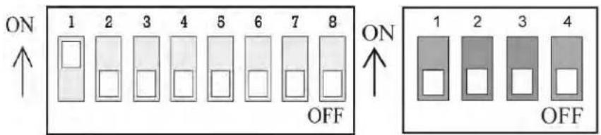
Default ID: 1
Default Baud Rate: 2400
Default Protocol: Pelco-D
3.1 ACCESSING THE DIP SWITCHES
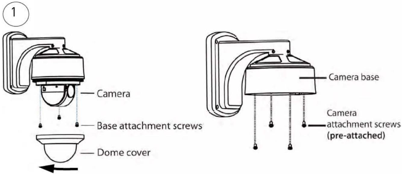
The DIP switches are located on the bottom of the camera. To access the DIP switches, you must remove the camera from the wall mount. Rotate the dome cover counterclockwise to remove. Remove the base attachment screws (3x) and lift the camera from the camera base. See illustration below.
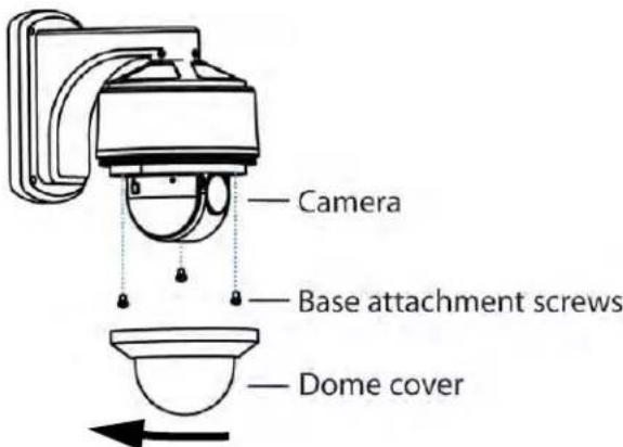
Removing the camera from the wall mount
3.2 SETTING THE CAMERA ID
Camera ID is set using the larger DIP switch panel with 8 switches. Each switch represents a binary digit (i.e. switch #1=1, #2=2, #3=4, etc.). Camera ID can be anything between 1-255. See the address example table on the next page.

Camera ID DIP Switches
IMPORTANT
You cannot use the same ID for more than 1 PTZ camera.
You cannot set an ID with a value of 0.
To calculate the ID, add up the Value shown for each switch that is ON.
EXAMPLE: If switches #1, #2, and #3 are ON, ID = 1 + 2 + 4 = 7.
3.3 SETTING THE CAMERA PROTOCOL AND BAUD RATE
Protocol and baud rate are set using switches 1&2 on the smaller DIP switch panel. See the table below.
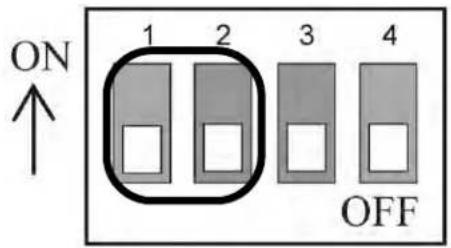
Protocol and Baud Rate Switches
| 1 2 Protocol/Baud Rate | ||
| OFF OFF Pelco-D 2400 | ||
| ON OFF Pelco-D 9600 | ||
| OFF ON Pelco-P 4800 | ||
| ON ON Pelco-P 9600 | ||
IMPORTANT
Switches 3 & 4 are for manufacturer use only and should always be set to OFF.
4. INSTALLATION
4.1 INSTALLATION WARNINGS

Make sure to install the camera in a location that can support the camera weight.
Make sure there are no live electrical cables in the area where you plan to mount the camera.
- Camera rated for outdoor use and is weatherproof only when using the included wall mount or accessory ceiling mount (MNTV0XC). The camera is not intended for submersion in water.
- Mount the camera where the lens is away from direct and intense sunlight.
- Plan your cable wiring so that it does not interfere with power lines or telephone lines.
- Ensure that the camera wiring is not exposed or easily cut.
- Mount the camera in an area that is visible but out of reach.
4.2 WALL MOUNT INSTALLATION (INDOOR/OUTDOOR)
To install the camera:
- If necessary, change the camera's ID and protocol information. See "Changing Protocol Information" on page 5.
- Use the back of the wall mount to mark holes for the wall mount screws and cable and drill the holes.
-
Connect the cables (see "Connecting the Camera" on page 2).
-
Attach the camera and wall mount to the wall using the wall mount screws (4x).

NOTE: Use the included drywall plugs if installing in drywall.
- Remove protective vinyl sheet from the dome cover.
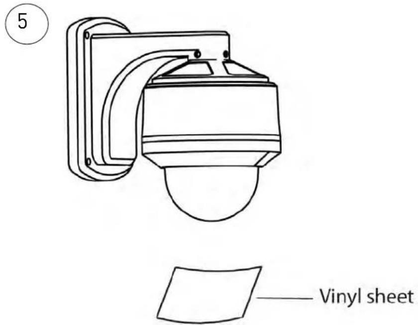
4.3 CEILING MOUNTING (INDOOR ONLY)

Camera is not weatherproof if installed using this method.
Use the included wall mount or accessory ceiling mount (not included) for outdoor installations.

Make sure to disconnect power before installing the camera.
Camera will begin moving immediately when power is connected.
To install the camera:
-
You must remove the camera from the included wall mount for indoor ceiling mounting. To do so:
-
Rotate the dome cover counterclockwise to remove.
- Remove the base attachment screws (3x) and remove the camera from the camera base.
- Remove the camera base by removing the camera attachment screws inside the wall mount (4x).
- Disconnect the video and alarm cables from the camera.

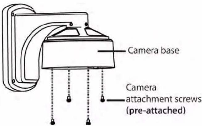
-
If necessary, change the camera's ID and protocol information. See "Changing Protocol Information" on page 5.
-
Remove the adhesive from the foam pad. Remove the cutouts for the cables and mounting screw holes and attach the foam pad to the bottom of the camera base with the cutouts aligned with the screw and cable holes.
-
A. If you are running the cables through the surface, remove the rubber plug on the bottom of the camera base and run the video cable and the alarm cable connectors through the bottom cable hole.
OR:
• B. If you are running cables through the side of the camera, unscrew the side conduit cap with a flathead screwdriver, and run the video cable and alarm cable connectors through the conduit hole.
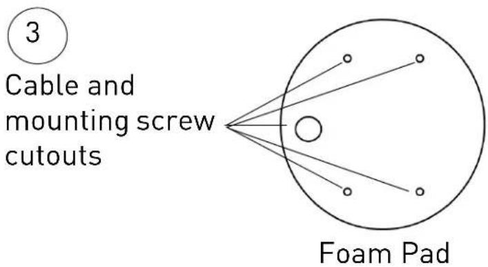


- Drill holes for the mounting screws (x4) and the cables and run the cables through the hole.
- Attach the camera base to the surface using the included ceiling/flush mounting screws (x4).
NOTE: Use the included dry wall anchors if installing the camera in drywall.
- Connect the video and alarm cable connectors to the camera.
NOTE: Make sure power is disconnected before connecting the video cable. Camera will begin moving immediately when power is connected.
- Attach the camera to the base using the base attachment screws (3x).


natural_image
Close-up of a black industrial sensor component with a connector, shown with a close-up view (no text or symbols visible)
Installation
-
Reattach the dome cover by rotating it clockwise. Remove protective vinyl from dome cover.
-
Connect cables as shown in "Connecting the Camera" on page 2.

4.4 FLUSH MOUNTING (INDOOR ONLY)

Camera is not weatherproof if installed using this method.
Use the included wall mount or accessory ceiling mount for outdoor installations.

Make sure to disconnect power before installing the camera.
Camera will begin moving immediately when power is connected.
-
You must remove the camera from the included wall mount for indoor flush mounting. To do so:
-
Rotate the dome cover counterclockwise to remove.
- Remove the base attachment screws (3x) and remove the camera from the camera base.
- Remove the camera base by removing the camera attachment screws inside the wall mount (4x).
- Disconnect the video and alarm cables from the camera.
-
If necessary, change the camera's ID and protocol information. See "Changing Protocol Information" on page 5.
-
Use the bottom of the camera as a guide to cut a hole approximately 103.5mm in diameter in the ceiling and run extension cables through the hole.
3
Use the bottom of the camera as a guide to cut a hole in the ceiling

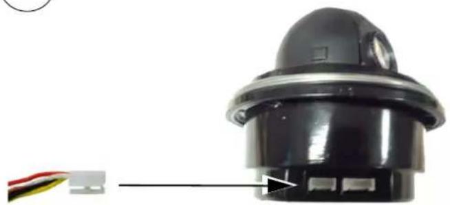
- Connect the video and alarm cable connectors to the camera. Connect cables as shown in "Connecting the Camera" on page 2.
NOTE: Make sure power is disconnected before connecting the video cable. Camera will begin moving immediately when power is connected.
4
natural_image
Close-up of a black industrial sensor component with a red and yellow connector, no visible text or symbols.- Insert the bottom of the camera through the hole and attach it to the ceiling using the ceiling/flush mounting screws (3x).

- Reattach the dome cover by rotating it clockwise. Remove protective vinyl from dome cover.

natural_image
Technical line drawings of a mechanical component with curved surfaces and a rotated base, showing progressive assembly (no text or symbols)5. USING THE OSD MENU
Use the OSD menu to control camera settings, presets, patterns, swings, groups and alarm input functions.
To access the OSD menu:
- On a Pelco D/P compatible controller, you can access the main menu by pressing and holding the [Menu] button for 2 seconds or by pressing [95] + [Preset].
- Press [Up]/[Down]/[Left]/[Right] to navigate the menu.
- Press [Near] to make menu selections or save values.
- Press [Far] to go up one level to previous menu.
- To change the value of an item press [Up]/[Down].
- The menu items surrounded with have sub menus.
Submenus:
- System Information: View information about the camera.
- Display Setup: Configure camera OSD.
- Dome Camera Setup: Configure camera image settings and PTZ functions.
- System Initialize: Reset camera settings to factory defaults.
5.2 DISPLAY SETUP
This menu allows you to turn sections of the OSD display ON or OFF. If an item is set to AUTO, the item is displayed only when its value is changed.
| DISPLAY SETUP | |
| →CAMERA ID | ON |
| PTZ | AUTO |
| ACTION TITLE | AUTO |
| RESET LABEL | AUTO |
| ALARM I/O | AUTO |
| <SET NORTH DIRECTION> | |
| BACK | |
| EXIT | |
- CAMERA ID [ON/OFF]: Shows the ID of the camera.
- PTZ [ON/OFF/AUTO]: Shows the camera's position.
- ACTION TITLE [ON/OFF/AUTO]: Shows the name of the currently selected action (e.g. Swing, Pattern, or Group).
- PRESET LABEL [ON/OFF/AUTO]: Shows the name of the currently selected preset.
- ALARM INPUT [ON/OFF/AUTO]: Shows alarm I/O status.
NOTE: Privacy Zone is not supported.
5.2.1 SET NORTH DIRECTION
SET NORTH DIRECTION
MOVE TO TARGET POSITION [NEAR:SAVE /FAR:CANCEL]
- Press [Near] to configure the camera compass direction. Move the camera into the desired North position and press [Near] again to save.
5.3 CAMERA SETUP
This menu allows you to configure camera image settings and PTZ functions.

5.3.1 CAMERA SETUP
Camera Setup allows you to set the general image settings of the camera.

- FOCUS MODE [AUTO/MANUAL/SEMIAUTO]: Sets camera focus mode. If set to SEMIAUTO, manual focus is used in preset operation, and Auto focus is used when manually controlling the camera. Focus information is saved when the preset is saved.
- DIGITAL ZOOM [ON/OFF]: Sets digital zoom function to ON/OFF. If this is set to OFF, zoom function stops at the optical zoom magnification limit
• LINE LOCK [ON/OFF]: Not applicable. - IMAGE FLIP [ON/OFF]: Flips image horizontally and vertically when set to ON.
White Balance Setup

White Balance mode is set to AUTO, and cannot be changed.
Auto Exposure Setup

- BACKLIGHT [ON/OFF]: Turns Backlight Compensation ON/OFF.
- DAY/NIGHT [AUTO1/AUTO2/DAY/NIGHT]: Select Day/Night mode. DAY is for a color image, and NIGHT is black and white. AUTO1/AUTO2 change between day and night mode based on luminance level of the scene. AUTO1 changes between Day/Night mode faster than AUTO2.
- BRIGHTNESS [0\~100]: Adjusts brightness of images. Iris, Shutter Speed, and Gain are adjusted automatically in correspondence with Brightness value.
- IRIS [AUTO]: AUTO is the default setting; it cannot be changed.
- SHUTTER SPEED [ESC/A. Flicker/Manual(x128\~1/120000 sec)]: ESC is the default setting; it cannot be changed.
- AGC [OFF/NORMAL/HIGH]: Enhances image brightness automatically if luminance level of image signal is too low.
- SSNR [OFF/LOW/MIDDLE/HIGH]: Enhances images by reducing noise when gain level is too high.
- SENS-UP [AUTO(2\~128)/OFF]: Enables/disables Slow Shutter function when luminance of image (signal) is too dark. When set to AUTO, you can set the limit for the Slow Shutter function.
5.3.2 MOTION SETUP
Motion Setup allows you to setup the motion settings of the camera.
| MOTION SETUP | |
| →MOTION LOCK | ON |
| PWR UP ACTION | ON |
| AUTO FLIP | ON |
| JOG MAX SPEED | 140/SEC |
| JOG DIRECTION | NORMAL |
| FRZ IN PRESET | |
| <PARKING ACTION SETUP> | |
| <ALARM INPUT SETUP> | |
| BACK | |
| EXIT | |
- MOTION LOCK [ON/OFF]: When set to ON, Motion Lock prevents Presets, Auto Pans, Patterns and Groups from being overwritten using the keyboard controller shortcuts. You may still run those functions using shortcuts or edit them using the OSD menu.
- POWER UP ACTION [ON/OFF]: When set to ON, after starting up, the camera will resume the last action executed before powering down. Preset, Pattern, Swing and Group may be resumed but Jog actions may not be resumed.
- AUTO FLIP [ON/OFF]: When set to ON, image is automatically flipped when tilt goes past 90^ . When set to OFF, tilt is limited to 90^ .
- JOG MAX SPEED [1\~360/Sec]: Sets maximum jog speed. Jog speed is inversely proportional to zoom magnification. As zoom magnification goes up, pan/tilt speed goes down.
- JOG DIRECTION [INVERSE/NORMAL]: When set to NORMAL, pan/tilt moves in the same direction as the joystick. If set to INVERSE, pan/tilt moves in the opposite direction.
- FREEZE IN PRESET [ON/OFF]: If set to ON, image freezes while moving between presets.
Parking Action Setup
Parking action runs an assigned command if the controller is idle for a set time between 1 minute and 4 hours.
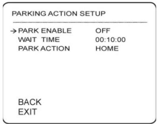
- PARK ENABLE [ON/OFF]: Enable/disable parking action.
- WAIT TIME [1 minutes\~4 hours]: The time is displayed in "hh:mm:ss" format.
- PARK ACTION [HOME/PRESET/PATTERN/SWING/GROUP]: Action taken after Wait Time. If HOME is selected, camera will move to home position.
Alarm Input Setup
Match the Alarm sensor input to an action. If an external sensor is activated, camera will move to the corresponding preset position or perform the corresponding action.

- ALARM TYPE Normal OPEN(N.O) / Normal CLOSE]: Sets sensor input type.
- ALARM ACTION [NOT USED/HOME/PRESET/GROUP/PATTERN]: You can assign an action for each Alarm input (Preset, Swing, Pattern and Group).
5.3.3 PRESET SETUP
A maximum 127 of positions can be stored as presets. Preset numbers can be assigned from 1 to 128.
NOTE: Preset "95" is reserved for starting the main menu.
Presets can be set using keyboard shortcuts or the OSD menu.
To set presets using keyboard shortcuts:
- Press [1\~128] then press [Set] for 2 seconds.
To go to presets using keyboard shortcuts:
- Press [1\~128] then press [Preset].
To set presets using the OSD menu:
- Go to the Preset Setup menu (Menu→Dome Camera Setup→Preset Setup).
- Configure the following:
- PRESET Number [1\~128]: If a selected preset is already defined, camera moves to pre-defined position and preset characteristics show on monitor. If a selected preset is not defined, UNDEFINED shows on monitor.
- EDIT PRESET SCENE: Press [Near] to redefine current Preset scene position. Then use the joystick to edit the position and press [Near] to save or [Far] to cancel.
![EDIT SCENE - PRESET 1 MOVE TO TARGET POSITION [NEAR:SELECT/ FAR:CANCEL] 0/0/x1/N](/content/2026/05/976010/images/c0c119d00b898b3b07024d0e9c9c41d2ca7f35685b362efd558ccc59119f12f3.jpg)
- EDIT PRESET LABEL: Press [Near] to edit Label shown on monitor when preset runs. Max. 10 characters are allowed. Use [Left/Right/Up/Down] to move the character selector and press [Near] to enter a character. Select OK and then press [Near] to confirm Label.
![LABEL - PRESET 1 →[■] 1234567890 OK ABCDEFGHIJKLMNOPQRSTUVWXYZabc KLMNOPQRST CANCEL uvwXYZabcd efghijklmn opqrstuvwx yz<>>-/:. --------](/content/2026/05/976010/images/9ba94a51a28adf573ac6610373a26e40b945d6e787346f5d179a26104a95e7c5.jpg)
- CAM ADJUST [GLOBAL/LOCAL]: Select GLOBAL to use the WB and AE settings that are set in this camera for this preset. Select LOCAL and press [Near] to define custom WB or AE settings for this preset.
5.3.4 SWING SETUP
You can setup up to 8 swings.
During a swing, the camera moves between 2 Preset positions repeatedly. When Swing function runs, the camera moves from the preset assigned as the 1st point to the preset assigned as the 2nd point in CW (Clockwise) direction. Then, the camera moves from the preset assigned as the 2nd point to the preset assigned as the 1st point in CCW (Counterclockwise) direction.
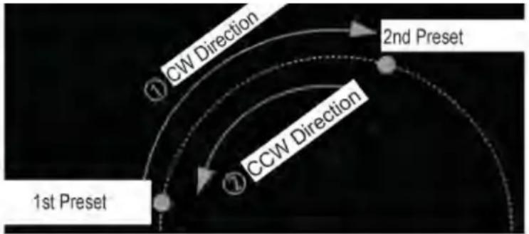
If the preset assigned as the 1st point is the same as the preset assigned as the 2nd point, camera turns on its axis by 360^ in CW (Clockwise) direction and then it turns on its axis by 360^ in CCW (Counterclockwise) direction.
Speed can be set up from 1^ /sec to 180^ /sec.
To run a swing using keyboard controller shortcuts:
- Press [141\~148] and then press [Preset] to runs swings 1 \~ 8.
To create swings:
-
Setup the desired presets you would like to use to create Swings.
-
Go to the Swing Setup menu (Menu→Dome Camera Setup→Swing Setup).
| SWING SETUP | |
| → SWING NO. | 1 |
| 1ST POS. | NOT USED |
| 2ND POS. | NOT USED |
| SWING SPEED | 30/SEC |
| CLEAR SWING | CANCEL |
| BACK | |
| EXIT | |
-
Configure the following:
-
SWING NUMBER [1\~8]: Selects Swing number to edit. If a selected Swing has not defined, NOT USED is displayed under 1st Position and 2nd Position.
- 1ST/2ND POSITION [PRESET 1\~128]: Set up the 2 positions for Swing function. If a selected preset is not defined, UNDEFINED will be displayed under the 2nd Position.
- SWING SPEED [1°/sec\~180°/sec]: Sets Swing speed from 1° / sec to 180° / sec.
- CLEAR SWING [CANCEL/OK]: Select OK and press [Near] to delete current Swing data.
5.3.5 PATTERN SETUP
You can set up to 4 Patterns with a maximum of 1200 communication commands each.
Creating a Pattern memorizes a path (mostly curve path) defined by the keyboard controller to be run later.
Patterns can be created using keyboard controller shortcuts or the OSD menu.
To create a Pattern using keyboard controller shortcuts:
- Press [1\~4] and press [Pattern] for 2 seconds. Define the pattern motion and then press [Near] to save or [Far] to cancel.
To run a Pattern using keyboard controller shortcuts:
- Press [1\~4] and then press [Pattern].
To create a Pattern using the OSD menu:
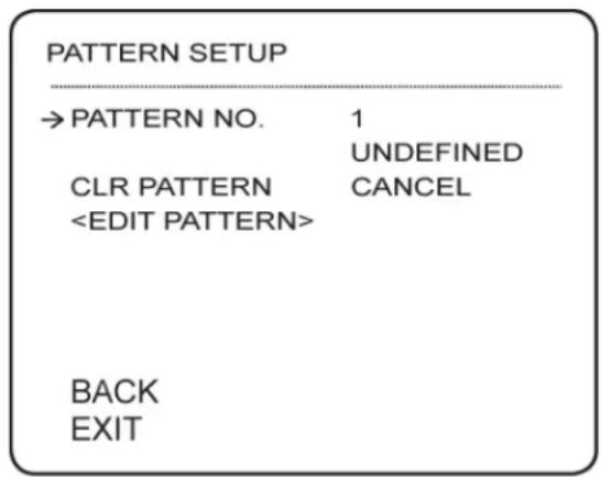
- Go to the Pattern Setup menu (Menu→Dome Camera Setup→Pattern Setup).
-
Configure the following:
-
PATTERN NUMBER [1\~4]: Selects Pattern number to edit. If a selected pattern number is not defined, UNDEFINED is displayed under selected pattern number.
- CLEAR PATTERN [CANCEL/OK]: Select OK to and then press [Near] to delete data in current pattern.
- EDIT PATTERN: Press [Near] to start editing pattern. Move the joystick to the desired start position and press [Near] to save. Move the joystick to the desired end position and press [Near] to save or [Far] to cancel.
5.3.6 GROUP SETUP
The Group function allows you to create a sequence of Presets, Patterns, and/or Swings. A maximum of 8 Groups can be stored with up to 20
actions each. The dwell time is the time interval between actions and is adjustable in the menu.
To run a group using keyboard controller shortcuts:
- Press [151\~158] and then press [Preset] to run groups 1 \~ 8.
To setup a group:
- Go to the Group Setup menu (Menu→Dome Camera Setup→Group Setup).

- Under Group Number, select a group number between 1\~8.
- Select Edit Group and press [Near].
![EDIT GROUP 1 NO. ACTION ### DWELL OPT → 1 NONE 2 NONE 3 NONE 4 NONE 5 NONE SAVE CANCEL [NEAR:EDIT]](/content/2026/05/976010/images/f9971861802bebb12ec7fd75b1b66be2d1ffc52503f8b67336bafe83e365800a.jpg)
- Press [Near] in NO ACTION.
- Move cursor [Up/Down] and press [Near] to configure functions. Configure the following settings for each function:
• ACTION: Type of action.
-
: Action number.
- DWELL: Dwell time in mm:ss between 1 sec.\~4 min.
-
OPT: Preset speed (2\~360) when preset is selected. Or, number of repetitions (1\~255) when Pattern or Swing is selected.
-
Press [Near] to confirm each function and repeat step 5 to configure up to 20 functions.
- Press [Far] when finished editing the group functions.
- Select SAVE and press [Near] to save the group or [Far] to discard.
The System Initialize menu allows you to reset settings to factory defaults or reboot the camera.
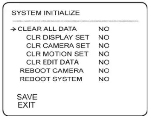
- CLEAR ALL DATA: Resets all configuration data, including display, camera, and motion setup.
- CLEAR DISPLAY SET: Resets Display settings.
- CLEAR CAMERA SET: Resets Camera settings.
- CLEAR MOTION SET: Resets Motion settings.
- CLEAR EDIT DATA: Deletes all Preset, Swing, Pattern, and Group data.
- REBOOT CAMERA: Reboots camera module.
- REBOOT SYSTEM: Reboots speed dome camera.
To initialize one of the options:
- Select the desired option using [Up/Down] and then press [Near]. Use [Up/Down] to select YES and then press [Near] again. Wait for the operation to complete.
5.5 RESERVED KEYBOARD SHORTCUTS
Some preset numbers are reserved for direct access to specific functions in OSD menu.
Function:
• [95] + [Preset]: Open main menu.
- [131\~134] + [Preset]: Runs Pattern Function 1 \~ 4.
• [141\~148] + [Preset]: Runs Swing Function 1 \~ 8.
• [151\~158] + [Preset]: Runs Group Function 1 \~ 8.
• [170] + [Preset]: Sets Camera BLC Mode to OFF.
• [171] + [Preset]: Sets Camera BLC Mode to ON.
• [174] + [Preset]: Sets Camera Focus Mode to AUTO.
• [175] + [Preset]: Sets Camera Focus Mode to MANUAL.
• [176] + [Preset]: Sets Camera Focus Mode to SEMI-AUTO.
• [177] + [Preset]: Sets Camera Day & Night Mode to AUTO.
• [178] + [Preset]: Sets Day & Night Mode to NIGHT.
• [179] + [Preset]: Sets Day & Night Mode to DAY.
• [190] + [Preset]: Sets OSD Display Mode to AUTO.
• [191] + [Preset]: Sets OSD Display Mode to OFF.
• [192] + [Preset]: Setting OSD Display Mode to ON.
6. TECHNICAL SPECIFICATIONS
| Image Sensor 1/3" Sony Ex-View HAD | CCD II |
| Video Format NTSC | |
| Effective Pixels 976(H) x 494 (V) | |
| Resolution 700+ TVL | |
| Range 360° Pan (Endless) | 155° Tilt (Auto-Flip) |
| Pan/Tilt Speed Max 360° / sec. | |
| Zoom 10x Optical Zoom & 10x Digital | Zoom |
| Protocol Pelco-D, Pelco-P | |
| Min. Illumination 0.7 Lux in Color | 0.02 Lux in Black and White |
| Lens / Lens Type Auto Focus / 3.8-38mm F 1.8 | |
| S / N Ratio 50db (AGC Off) | |
| Iris Auto Iris | |
| Termination BNC Video / RS485 / DC | Power / Alarm (4 inputs) |
| Video Output | Composite 1.0Vpp @ 75ohm |
| Power Requirement | 12V DC ±10% |
| Power Consumption | Max. 850mA/ 7.2W |
| Operating Temperature Range | -4°F ~ 122°F / -20°C ~ 50°C |
| Operating Humidity Range | within 90%RH |
| Indoor/Outdoor | Both(IP661) |
| Weight | 1.4kg / 3.0lbs (with wall mount)2.15lbs / 0.96kg (camera only) |
- Camera is weatherproof only when using included wall mount or accessory ceiling mount. Not intended for submersion in water. Installation in a sheltered location recommended.
7. DIMENSIONS
Units: mm
Camera and wall mount dimensions
Ceiling mount dimensions
Flush mount dimensions


8. TROUBLESHOOTING
There is no picture at night
- Camera is capable of seeing in extremely low light conditions (0.02 Lux), but it cannot see in total darkness. It is recommended to install the camera where there is some ambient light (e.g. street lighting or starlight, moonlight, etc.) or leave a light on in the area where the camera is installed.
- Sens-Up is OFF. Go to MENU→DOME CAMERA SETUP→CAMERA SETUP→AUTO EXPOSURE SETUP and make sure that Sens-Up is set to AUTO. Press [Near] and adjust the Sen-Up Limit to provide the best night time picture for your installation.
No image at startup or camera image is unclear
- Check to ensure your camera is properly connected (see “Connecting the Camera” on page 2) and the power adapter is plugged in.
- Connect the power adapter to a different outlet.
- Make sure that the power adapter you are using meets the camera's power requirements (850mA / 7.2W / 12V DC).
- Extension cable run may be too long. Voltage may drop over distance and affect image quality.
- Dome cover is dirty. Clean the dome cover with a soft, slightly damp cloth. Do not use anything other than water to clean the dome cover, as chemicals such as acetone can permanently damage the plastic.
PTZ controls are not working or are not working properly
- RS485 wires not connected or connected using wrong polarity. Ensure the red wire is connected to the + RS485 port and the black wire is connected to the - RS485 port.
- Not enough of RS485 wire is exposed to make proper connection. Use a wire stripper (not included) to strip off some of the wire insulation.
- Extension cables may be damaged or are not connected properly. Check your extension cable run.
- PTZ protocol details are not configured in DVR/keyboard controller. See your DVR/keyboard controller instruction manual for details.
- Multiple PTZ cameras are using the same camera ID. This will either disable or affect PTZ controls. Configure a separate camera ID for each camera (see “Setting the Camera ID” on page 6 for details).
Need Help?
Please make sure to visit our website www.digimerge.com to receive product updates and information.
3 Easy Ways To Contact Us

natural_image
Man using a laptop on a white sofa, no visible text or symbols
natural_image
Man using a laptop in an office setting (no visible text or symbols)
natural_image
Woman sitting at a desk with a computer and water bottle, smiling at the camera (no visible text or symbols)Online:
Product support is available 24/7 including product info rm ation, user manuals, quick start up gui de s and FAQ's at w ww. digi merge.com
By Email:
Te ch ni cal support (for tec hn ical/installat io n is su es) tech@digimerge.com
By Phone:
No rt h Am er ica: 1-866-816-5919 Te ch ni cal support (for tec hn ical/installat io n is su es) Mo n- Fri 8.00 a m to 8.00pm EST

natural_image
Close-up of a smiling man wearing a headset, with another person partially visible in the background (no text or symbols)We welcome your feedback at info@digimerge.com
For more information, visit www.digimerge.com

DIG!MERGE | Right for Business
DEZ06T10
English Version 1.0
- DIG!MERGE | Right for Business
- DEZ06T10
- TDN Mini Outdoor 10X PTZ Camera
- Instruction Manual
- CAUTION
- Features
- Safety Instructions
- TABLE OF CONTENTS
- Getting Started .... 1
- Connecting the Camera 2
- Changing Protocol Information .... 5
- Installation 9
- Using the OSD Menu....18
- Technical Specifications .... 33
- Dimensions .... 34
- Troubleshooting 35
- GETTING STARTED
- OPTIONAL ACCESSORIES
- CONNECTING THE CAMERA
- DEFAULT PROTOCOL INFORMATION
- POWER REQUIREMENTS
- RS485 CONNECTION
- ALARM INPUT CONNECTION
- CHANGING PROTOCOL INFORMATION
- ACCESSING THE DIP SWITCHES
- SETTING THE CAMERA ID
- IMPORTANT
- SETTING THE CAMERA PROTOCOL AND BAUD RATE
- INSTALLATION
- INSTALLATION WARNINGS
- WALL MOUNT INSTALLATION (INDOOR/OUTDOOR)
- To install the camera:
- CEILING MOUNTING (INDOOR ONLY)
- Camera is not weatherproof if installed using this method.
- Make sure to disconnect power before installing the camera.
- OR:
- Installation
- FLUSH MOUNTING (INDOOR ONLY)
- USING THE OSD MENU
- To access the OSD menu:
- Submenus:
- DISPLAY SETUP
- SET NORTH DIRECTION
- CAMERA SETUP
- CAMERA SETUP
- White Balance Setup
- Auto Exposure Setup
- MOTION SETUP
- Parking Action Setup
- Alarm Input Setup
- PRESET SETUP
- To set presets using keyboard shortcuts:
- To go to presets using keyboard shortcuts:
- To set presets using the OSD menu:
- SWING SETUP
- To run a swing using keyboard controller shortcuts:
- To create swings:
- PATTERN SETUP
- To create a Pattern using keyboard controller shortcuts:
- To run a Pattern using keyboard controller shortcuts:
- To create a Pattern using the OSD menu:
- GROUP SETUP
- To run a group using keyboard controller shortcuts:
- To setup a group:
- To initialize one of the options:
- RESERVED KEYBOARD SHORTCUTS
- Function:
- TECHNICAL SPECIFICATIONS
- DIMENSIONS
- TROUBLESHOOTING
- There is no picture at night
- No image at startup or camera image is unclear
- PTZ controls are not working or are not working properly
- Need Help?
- Easy Ways To Contact Us
- Online:
- By Email:
- By Phone:
- English Version 1.0
Brand : Digimerge
Model : DEZ06T10
Category : Security Camera