SR-GM14H - Car radio Stinger - Free user manual and instructions
Find the device manual for free SR-GM14H Stinger in PDF.


| Product Type | Car Stereo with CD/MP3/USB/AUX |
| Dimensions (W x H x D) | 178 mm x 50 mm x 160 mm (Standard DIN) |
| Weight | 1.2 kg |
| Power Output | 4 x 50 Watts (Max) |
| Power Supply | 12V DC (Negative Ground) |
| Display | LCD with White Backlight |
| Radio Bands | AM/FM with RDS |
| Playback Formats | CD, CD-R/RW, MP3, WMA |
| Audio Inputs | Front USB, Front AUX (3.5mm) |
| Audio Outputs | 4-Channel Preamp (RCA) + Subwoofer Output |
| Equalizer | 3-Band EQ (Bass, Middle, Treble) |
| Preset Stations | 30 (18 FM + 12 AM) |
| Remote Control | Yes, IR Remote Included |
| Steering Wheel Control | Compatible (Adapter Required) |
| Security | Detachable Faceplate with Carry Case |
| Maintenance & Cleaning | Wipe faceplate with soft, dry cloth. Avoid liquids. |
| Spare Parts & Repairability | Fuse (10A ATC/ATO), Faceplate available from support. |
| General Information | ISO DIN mounting, ISO connectors. |
Frequently Asked Questions - SR-GM14H Stinger
User questions about SR-GM14H Stinger
0 question about this device. Answer the ones you know or ask your own.
Ask a new question about this device
Download the instructions for your Car radio in PDF format for free! Find your manual SR-GM14H - Stinger and take your electronic device back in hand. On this page are published all the documents necessary for the use of your device. SR-GM14H by Stinger.
USER MANUAL SR-GM14H Stinger
Introduction and Features
The SR-GM14H is a complete radio replacement kit for the installation of the Stinger HEIGH10® modular radio in Chevrolet Silverado and GMC Sierra trucks. All modules, cables and adapters are included to retain important features of the factory system, including: OnStar, front and rear park assist, warning chimes, factory reverse camera, steering wheel-mounted radio controls and AM/FM reception. Plug & Play wiring harnesses allow for quick and easy installation without the need to cut or splice any wiring. The display mounting panel allows flush mounting the 10 inch display without modifying/cutting any part of the vehicle's sub-dash.
Important Notes
We recommend reading this manual thoroughly to familiarize yourself with the entire process prior to beginning the installation.
- Does not retain the following factory features:
• Factory satellite radio
• Rear seat entertainment system (RSE)
• Steering wheel control backlighting
- Factory USB Ports
- Not compatible with vehicles equipped with Bose amplified audio system.
- Please make your vehicle settings selections before removing the factory radio for optimal installation time. Once the radio has been removed, the vehicle settings which are normally selected through the factory radio can be accessed and changed by downloading and installing the PAC Vehicle Settings program from http://www.pac-audio.com/firmware
- The Voice button can be set to activate the factory OnStar function when pressed for longer than 1.5 seconds or given the ability to control the aftermarket radio. This option can be found in the PAC Vehicle Settings program mentioned above in note three. The default setting for this button is to control the factory OnStar. If this button is set to control the aftermarket radio, OnStar can still be accessed by using the mirror controls.
Recommended Tools
Plastic Panel Tool
7mm Socket
10mm Socket
Ratchet
Torx T15 Screwdriver
Small Flat-blade Screwdriver
Pick Tool
Wire Feeder
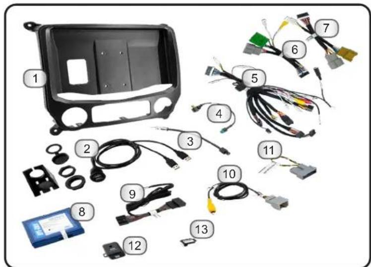
Included Components
- HEIGH10 Display Mounting Panel
- Dual USB Extension (SSUSB2)
- AM / FM Antenna Adapter (BAA22)
- Satellite Antenna Adapter (SAT-01)
- Main Harness (SR-GM14H-HAR-A)
- Vehicle Side Harness B (SR-GM14H-HAR-B)
- Vehicle Side Harness C (SR-GM14H-HAR-C)
- Radio Replacement Interface (RP5-GM51)
- Steering Wheel Control Harness (GM5LIN-SW-HAR)
- Factory Rear Camera Adapter (CAM-GM51)
- IOB Display Harness (GM5CAM-DIS-HAR)
- Chime Module (CMX)
- Differential Video Adapter (RPA-VA1)
NOTE: Along with the SR-GM14H components, additional hardware and wire harnesses from the HEIGH10 (UN1810) kit will also be used in the installation.
Wiring Overview
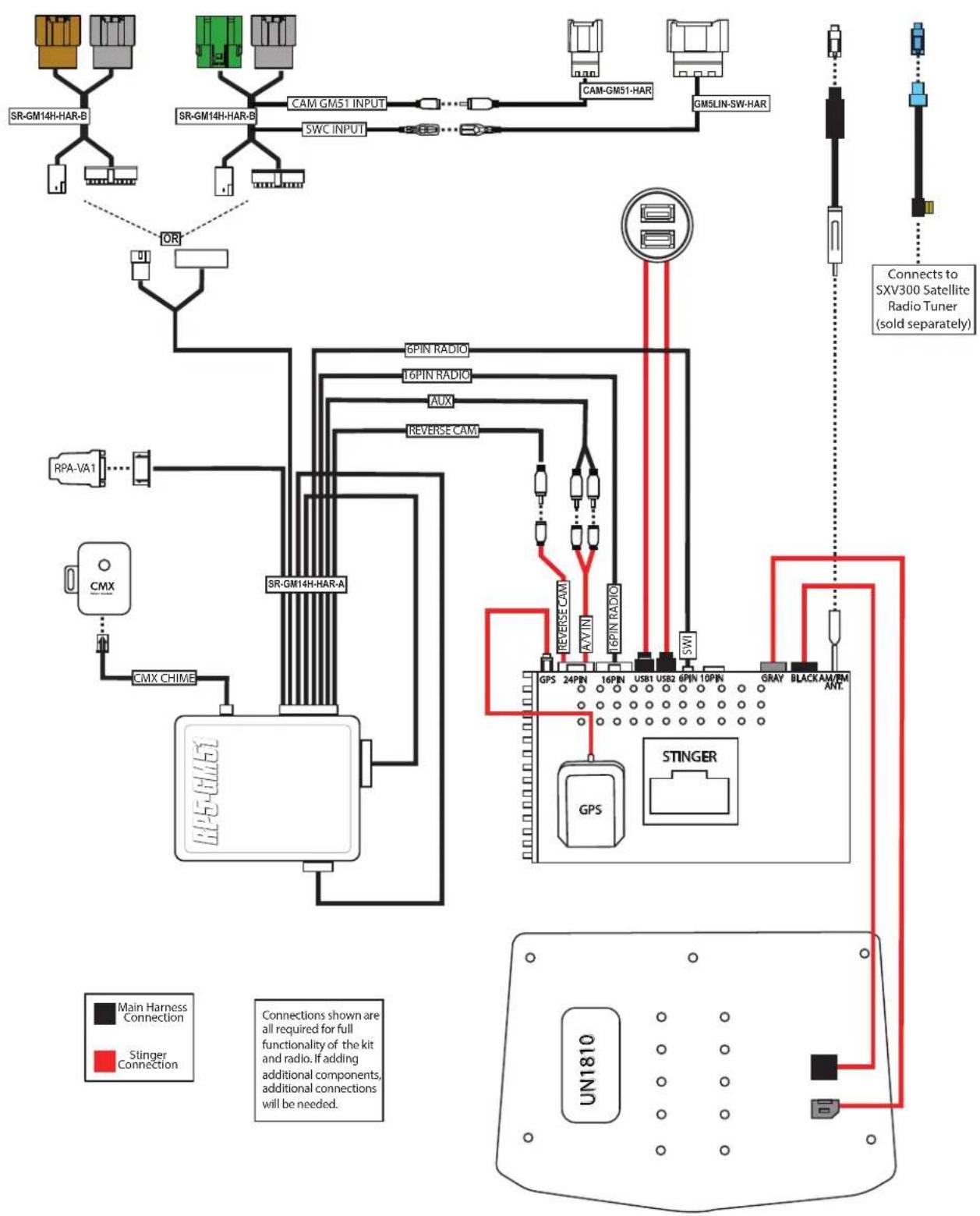
flowchart
graph TD
    A["SR-GM14H-HAR-B"] --> B["OR"]
    C["SR-GM14H-HAR-B"] --> D["SWC INPUT"]
    E["SR-GM14H-HAR-B"] --> F["CAM GM51 INPUT"]
    G["SR-GM14H-HAR-B"] --> H["SMC INPUT"]
    I["SR-GM14H-HAR-B"] --> J["SMC INPUT"]
    K["SR-GM14H-HAR-B"] --> L["SMC INPUT"]
    M["SR-GM14H-HAR-B"] --> N["SMC INPUT"]
    O["SR-GM14H-HAR-B"] --> P["SMC INPUT"]
    Q["SR-GM14H-HAR-B"] --> R["SMC INPUT"]
    S["SR-GM14H-HAR-B"] --> T["SMC INPUT"]
    U["SR-GM14H-HAR-A"] --> V["CMX CHIME"]
    W["SPIN RADIO"] --> X["REVERSE CAM"]
    Y["SPIN RADIO"] --> Z["REVERSE CAM"]
    AA["AUX"] --> AB["REVERSE CAM"]
    AC["GPS"] --> AD["STINGER"]
    AE["GPS"] --> AF["STINGER"]
    AG["STINGER"] --> AH["STINGER"]
    AI["GPS"] --> AJ["STINGER"]
    AK["GPS"] --> AL["STINGER"]
    AM["GPS"] --> AN["STINGER"]
    AO["GPS"] --> AP["STINGER"]
    AQ["GPS"] --> AR["STINGER"]
    AS["GPS"] --> AT["STINGER"]
    AU["GPS"] --> AV["STINGER"]
    AW["GPS"] --> AX["STINGER"]
    AY["AX'IN"] --> AZ["REVERSE CAM"]
    BA["SPIN RADIO"] --> BB["REVERSE CAM"]
    BC["USB1"] --> BD["STINGER"]
    BE["USB2"] --> BF["STINGER"]
    BG["6PIN 10PIN"] --> BH["STINGER"]
    BI["GRAY"] --> BJ["STINGER"]
    BK["BLACK"] --> BL["STINGER"]
    BM["PB/PM ANT."] --> BN["STINGER"]
    BO["UN1810"] --> BP["STINGER"]
    BQ["SIGNER Connection"] --> BR["SIGNER Connection"]
    BS["SIGNER Connection"] --> BT["SIGNER Connection"]
    BU["SIGNER Connection"] --> BV["SIGNER Connection"]
    BW["SIGNER Connection"] --> BX["SIGNER Connection"]
    BY["SIGNER Connection"] --> BZ["SIGNER Connection"]
    CA["SIGNER Connection"] --> CB["SIGNER Connection"]
    CC["SIGNER Connection"] --> CD["SIGNER Connection"]
    BECA["SIGNER Connection"] --> CE["SIGNER Connection"]
    BFCA["SIGNER Connection"] --> CF["SIGNER Connection"]
    BGCA["SIGNER Connection"] --> GD["SIGNER Connection"]
    BHCA["SIGNER Connection"] --> DH["SIGNER Connection"]
    BICA["SIGNER Connection"] --> BI["SIGNER Connection"]
Factory Radio Code
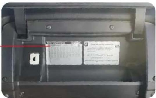
Before starting, determine the vehicle's factory audio system by referencing the Service Parts Identification sticker inside the upper glove box.
One of these RPO codes will be listed:
IO3, IO4, IO5, IO6 or IOB
The installations are very similar for each type of factory audio system, but there are differences referenced throughout this guide.
Note: The installation shown in this guide is IO5 with factory rear camera and steering wheel controls.
This installation manual will cover the necessary order of procedures to complete the installation efficiently and to avoid redoing any steps. The order will be as follows; Disassembly, In-Vehicle Harness Connections and Preparation, Interface and Main Harness Connections, Display Mounting Panel Preparation, Radio Module Preparation and Radio Unit Installation.
The installation steps shown are all required for full functionality of the radio. If adding additional components; cameras, amplifiers, satellite radio, etc., additional steps and harnesses will be needed.
Section 1: Disassembly
Part One: Center Dash Disassembly
natural_image
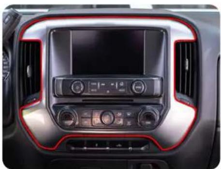
Interior view of a car dashboard with digital display and red accent trim (no visible text or symbols)Step 1
Remove the radio display/climate control trim panel using a plastic trim tool to release the retaining clips. Unplug any wire harnesses from the back of the trim panel, if equipped.

natural_image
Interior view of a car dashboard with air filters and a central touchscreen display (no visible text or symbols)
Remove the four 7mm screws securing the radio display/climate control panel. Pull outward to release the retaining clips. Remove all connectors from the back of the panel.
natural_image
Interior view of a car showing internal components and wiring (no visible text or symbols)Step 3 Step 2
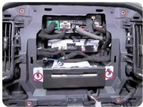
If equipped, remove the two 7mm screws from the CD/DVD mechanism, remove and unplug. (This plug will not be reconnected).
Section 1: Disassembly (cont.)
Part One: Center Dash Disassembly (cont.)
natural_image
Interior view of a car dashboard and air vent system (no visible text or symbols)Step 4
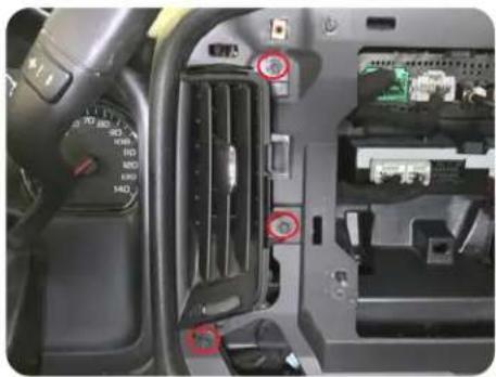
Remove the three 7mm screws securing the air vent on the left side of the radio opening and remove the vent.
Part Two: Lower Storage Compartment Removal
natural_image
Interior view of a car showing the dashboard and side panels with red arrows pointing to specific areas (no text or symbols visible)Step 1
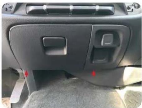
Remove the two Torx T15 screws from the bottom edge of the storage compartment.
natural_image
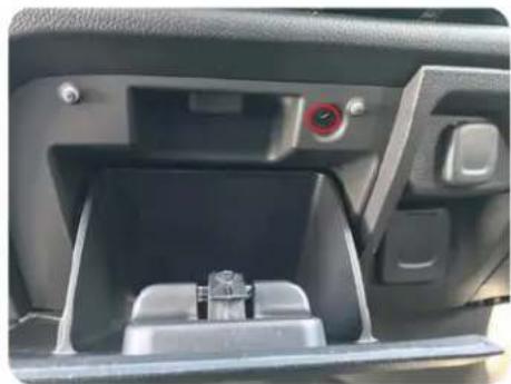
Interior view of a car showing the rear intake compartment with a small mechanical component inside (no visible text or symbols)Step 2
Remove the upper Torx T15 screw inside the storage compartment.
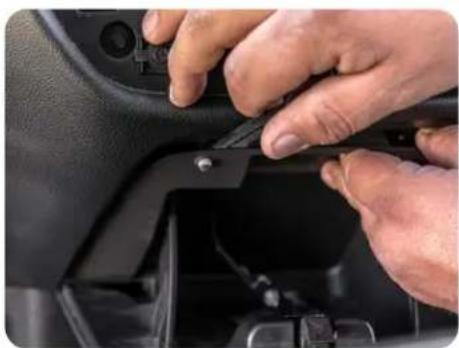
natural_image
Close-up of hands installing or adjusting a black plastic component on a car intake manifold (no visible text or symbols)Step 3
Using a panel tool or similar, release the top retaining clips and remove the storage assembly.
Section 1: Disassembly (cont.)
Part Three: Glove Box Removal (Optional)
If the vehicle is equipped with IO4, IO5 or IO6 radio AND a factory rear camera, follow the steps below to remove the glove box. For IO3 and IOB vehicles, or no factory rear camera, proceed to Part Four.
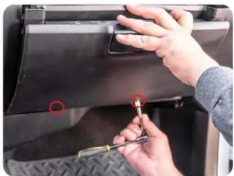
natural_image
Close-up of hands using a tool to adjust or install a black vehicle door panel (no visible text or symbols)Step 1
Remove the two Torx T15 screws from the bottom edge of the lower glove box.
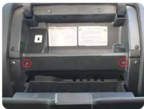
natural_image
Interior view of a car showing a mechanical component with two red circular markers indicating features (no visible text or symbols)Step 2
Open the upper and lower glove box doors and remove the two Torx T15 screws securing the lower glove box.
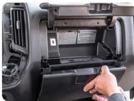
natural_image
Interior view of a car showing the rear compartment with a hand inserting a device into the door (no visible text or symbols)Step 3
Pull outward on the lower glove box to release the retaining clips and remove the lower glove box.
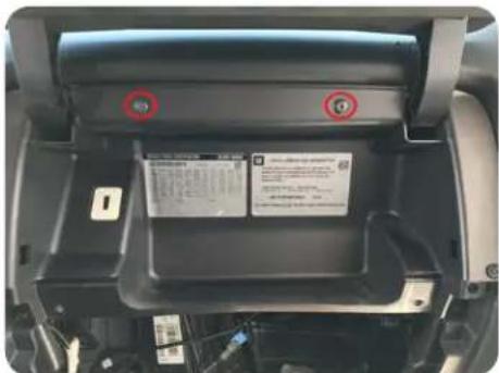
Step 4
Remove the two Torx T15 screws and pull to remove the upper glove box. Unplug the factory USB port from the backside.
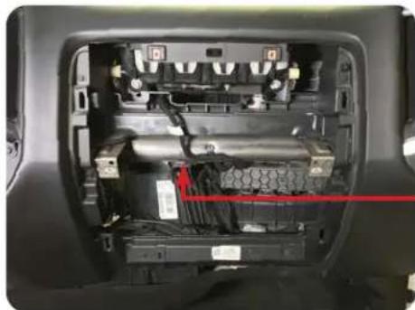
natural_image
Interior view of a car showing internal components and wiring (no visible text or symbols)Step 5
Up, behind the metal bar running across the inner dash, locate the HMI Module; black module with multiple colored plugs facing down.
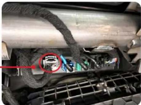
natural_image
Close-up of a car engine bay with visible wiring and component, no text or symbols presentStep 6
Unplug the gray 12 pin camera harness from the HMI module.
Section 1: Disassembly (cont.)
Part Four: A Pillar Removal
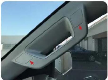
natural_image
Interior view of a car showing the dashboard and side mirror with red arrows pointing to the interior (no text or symbols visible)Step 1
Remove the inserts covering the bolts on the passenger A pillar handle.
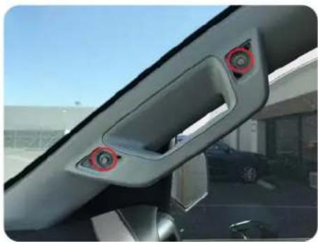
natural_image
Interior view of a car showing the rearview and side mirror with red circular buttons (no text or symbols visible)Step 2
Remove the two 10mm bolts.
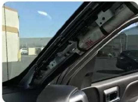
natural_image
Interior view of a car showing the hood and side panel, with no visible text or symbols.Step 3
Pull the trim panel to release the retaining clips and remove.
Part Five: Lower Steering Column Cover Removal (Optional)
If the vehicle is equipped with IO3, IO4, IO5 or IO6 radio AND steering wheel controls, follow the steps below to remove the lower steering column cover. For IOB vehicles or no steering wheel controls, proceed to Section Two on next page.
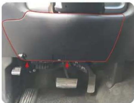
natural_image
Close-up of a vehicle's rear bumper with red outline and arrows indicating components (no visible text or symbols)Step 1
Remove the two Torx T15 screws from the bottom edge of knee panel below the steering column. Pull outward to remove the panel and lay carefully on the floor board.
natural_image
Close-up of a car interior showing a hand holding a small black component with a red arrow pointing to it (no visible text or symbols)Step 2
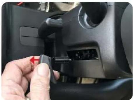
Remove the plastic handle from the steering wheel tilt lever by pulling outward, towards the driver's door on the handle. A trim tool may also be used if unable to remove by hand.
natural_image
Close-up of a car headset with hand operating the wheel (no visible text or symbols)Step 3
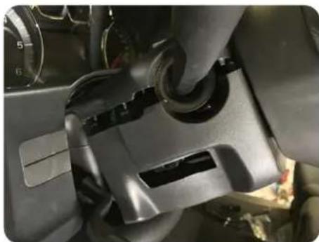
Pull downward on the lower cover on both sides to release the locking tabs and remove the lower cover.
Section 2: In-Vehicle Harness Connections and Preparation
Part One: Dual USB Extension (SSUSB2)
Apple CarPlay, Android Auto, and any Firmware Updates require access to a USB port. The SSUSB2 is designed to extend the USB ports on the back of the HEIGH10 to where they are accessible once the radio is installed.
For this installation, the factory 12V power outlet will be replaced with the SSUSB2. You may chose to follow these steps, or mount the USB port somewhere else in the vehicle. Please note, the factory USB ports will no longer function after the factory radio is removed.
natural_image
Close-up of a mechanical component with a yellow arrow pointing to a component (no visible text or symbols)Step 1
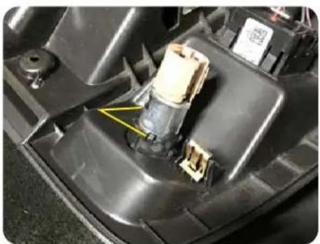
From the backside of the lower storage compartment, remove the metal insert from the power outlet by releasing the two retaining clips with a small pick and pushing out the front side.
natural_image
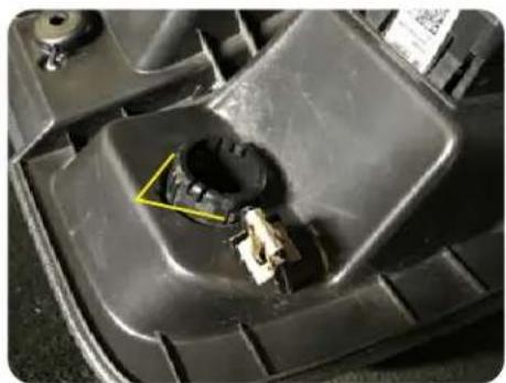
Close-up of a car engine compartment with a yellow warning triangle pointing to a component (no visible text or symbols)Remove the plastic sleeve by depressing the two tabs and pushing out the front.
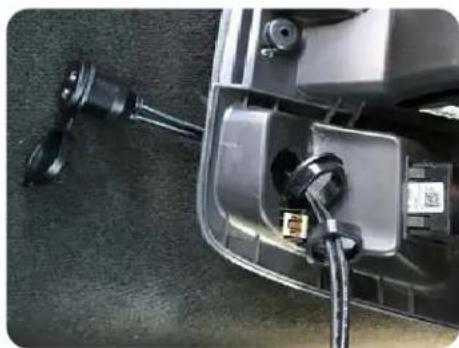
natural_image
Close-up of a car's front panel showing cable and plug connectors (no visible text or symbols)Step 3 Step 2
Install the optional USB cover and feed the USB cables through the front of the panel. Secure with the flanged nut and then lock with the lock nut.
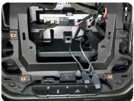
natural_image
Interior view of a car's backrest showing internal components and wiring (no visible text or symbols)Step 4
Route the USB cables up and out of the right side opening at the rear of the CD/DVD opening.
Section 2: In-Vehicle Harness Connections and Preparation (cont.)
Part Two: Factory Rear Camera Retention Harness (CAM-GM51-HAR)
If the vehicle is equipped with IO4, IO5 or IO6 radio AND a factory rear camera, follow the steps below to install the factory camera retention harness behind the glove box. For IO3 and IOB vehicles, or no factory rear camera, proceed to Part Four.
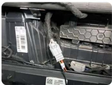
natural_image
Interior view of a vehicle battery pack with visible wiring and components (no readable text or symbols)Step 1
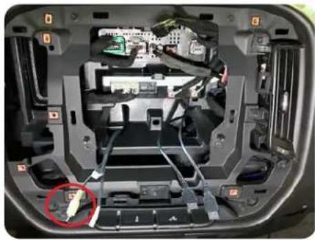
Plug the gray 12 pin camera harness from the HMI module into the CAM-GM51-HAR.
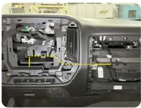
natural_image
Interior view of a car showing internal components and wiring (no visible text or symbols)Step 2
Route the yellow RCA end of the camera cable to the radio opening. Secure plug and cable with zip ties.
natural_image
Interior view of a car showing internal components and wiring, with no visible text or symbolsStep 3
Route the camera RCA out of the left side opening at the rear of the CD/DVD opening.
Part Three: Steering Wheel Control (SWC) Retention Harness (GM5LIN-SW-HAR)
If the vehicle is equipped with IO4, IO5 or IO6 radio AND steering wheel controls, follow the steps below to install the SWC retention harness at the steering column. For IO3 and IOB vehicles, or no steering wheel controls, proceed to Part Four.
natural_image
Close-up of automotive electrical connectors and wiring (no visible text or symbols)Step 1
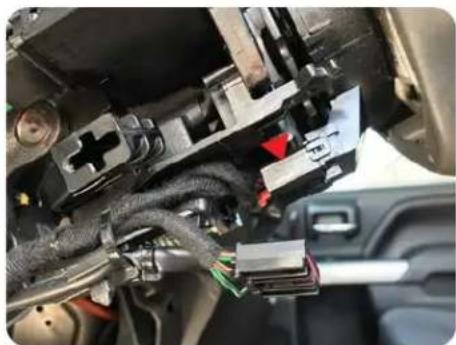
Locate and unplug the black 10 pin connector located on the underside of the steering column.
natural_image
Close-up of automotive electrical wiring and connectors in a vehicle (no visible text or symbols)Step 2
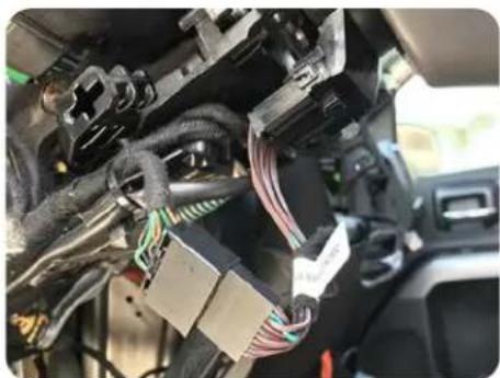
Plug the male connector into the female end of the GM5LIN-SW-HAR and plug the GM5LIN-SW-HAR male end into the female connector on the steering column.
natural_image
Close-up of automotive electrical connectors and wiring (no visible text or symbols)Step 3
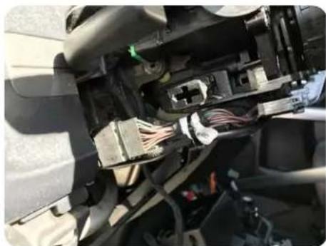
Secure the T-harness to the factory wire harness. Route the 50" single lead from the GM5LIN-SW-HAR to the radio opening, securing with zip ties.
Section 2: In-Vehicle Harness Connections and Preparation (cont.)
Part Three: Steering Wheel Control (SWC) Retention Harness (cont.)
natural_image
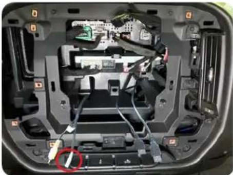
Interior view of a car showing internal components and wiring, with no visible text or symbolsStep 4
Route the steering wheel control lead into the CD/DVD area through the left side opening in the rear of the cavity.
Part Four: GPS Antenna
The GPS antenna is required for proper operation of Apple CarPlay and Android Auto, in addition to the optional GPS if installed. The GPS antenna is included in the HEIGH10 hardware.
natural_image
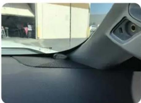
Close-up of a car's side profile showing the wheelrest and dashboard (no visible text or symbols)Step 1
Position the GPS antenna and route the antenna cable down into the glove box area. Replace the A pillar panel and ensure the cable does not interfere or get pinched.
natural_image
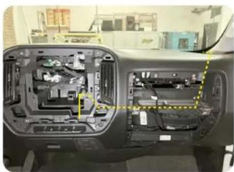
Interior view of a car showing internal components and wiring, with no visible text or symbolsStep 2
Continue routing the GPS cable across the inner dash towards the radio opening securing with zip ties.
natural_image
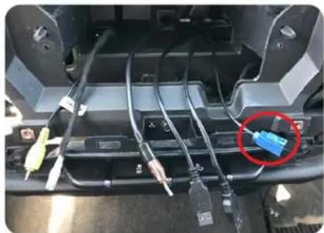
Close-up of a car chassis showing wiring and connectors, with one blue connector highlighted (no text or symbols visible)Step 3
Route the GPS cable into the CD/DVD area through the right side opening at the rear of the cavity.
Section 2: In-Vehicle Harness Connections and Preparation (cont.)
Part Five: Vehicle Side Plug Relocation and Antenna Adapter
natural_image
Interior view of a vehicle chassis with highlighted structural components (no visible text or symbols)Step 1
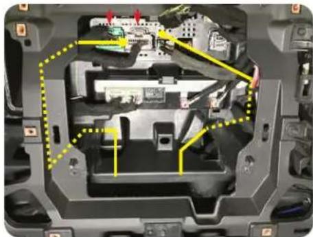
Unplug the Green and Gray or Mustard and Gray (IOB) connectors from the factory tuner and re-route them down and through the left opening of the lower CD/DVD area.
natural_image
Interior view of a device showing internal components with connectors and ports (no visible text or symbols)Step 2 Step 3
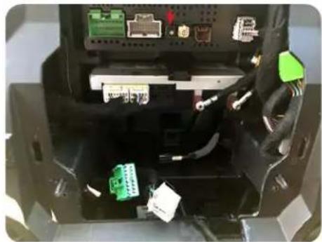
Unplug the Black antenna cable from the factory tuner and re-route it down and through the right side opening of the lower CD/DVD area.
natural_image
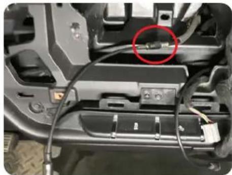
Close-up of a vehicle's internal components with visible wiring and a red circle highlighting a specific area (no text or symbols)Connect the BAA22 Antenna adapter to the factory antenna.
Section 3: Interface and Main Harness Connections and Preparation
Part One: RP5-GM51 Radio Interface Connections
natural_image
Close-up of a blue electronic device with a rotary dial and two black square buttons (no visible text or symbols)Step 1
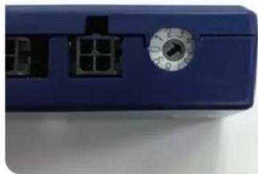
Using a small flat-blade screwdriver or similar, set the Radio Select Dial on the side of the RP5-GM51 to Number 4.
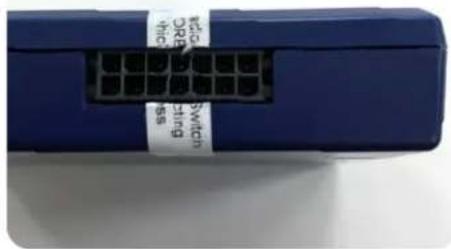
Remove the warning sticker on Vehicle Connections port on the other side of the RP5-GM51 module.
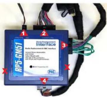
Step 3Step 2
Connect the four connectors from the SR-GM14H-HAR-A Main Harness to the indicated ports on the RP5-GM51 module.
Section 3: Interface and Main Harness Connections and Preparation
Part Two: Main Harness Connections (SR-GM14H-HAR-A)
natural_image
Close-up of a cable with various connectors and wires, no visible text or symbolsStep 4A
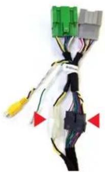
For IO3, IO4, IO5 and IO6 radios, connect the white 2-pin and the black 18-pin of the SR-GM14H-HAR-B to the Main Harness.
natural_image
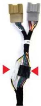
Close-up of a cable with various colored connectors and wires, no visible text or symbolsOR
Step 4B
For IOB radios, connect the white 2-pin and the black 18-pin of the SR-GM14H-HAR-C to the Main Harness.
natural_image
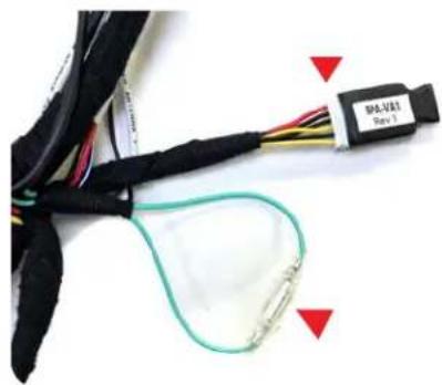
Close-up of a black cable with multiple wires and connectors, connected to a green cable with red triangular markers (no visible text or symbols)Step 5
Plug the 6-pin lead on the Main Harness into the RPA-VA1. Connect the male and female ends of the Light Green leads together.
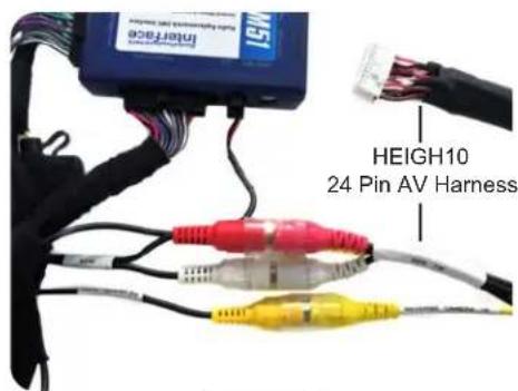
Step 6
Connect the HEIGH10's 24 pin AV Harness AUX IN to AUX on the Main Harness. Connect REVERSE CAMERA IN to REVERSE CAM.
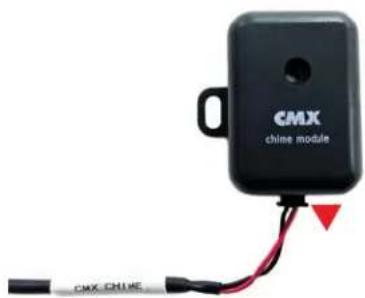
Step 7
Connect the CMX Chime Module to the 2 pin CMX Chime connector on the Main Harness.
Section Four: Display Mounting Panel Preparation
Part One: Transferring the Climate Controls
natural_image
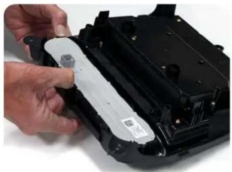
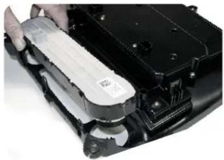
Close-up of hands installing a white plastic component on a black electronic device casing (no visible text or symbols)With the factory radio display / climate control panel face down, apply slight pressure to the front of the controls while releasing the locking tabs around the perimeter.
natural_image
Close-up of a hand holding a transparent plastic container over a black electronic device casing (no visible text or symbols)Step 2 Step 1 Step 3
Once all the clips are released, remove the climate controls from the factory bezel.
natural_image
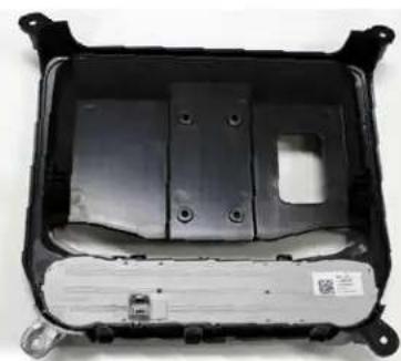
Interior view of a black plastic automotive chassis frame with visible mounting holes and internal compartments (no text or symbols)Align the controls in the HEIGH10 mounting panel and push to seat and lock all the retaining clips.
Part Two: Mounting the Display
natural_image
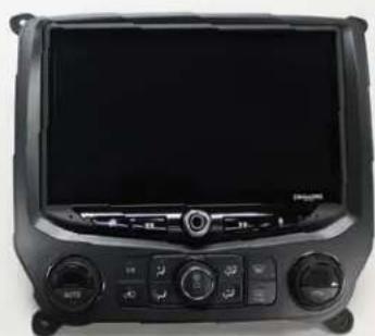
Front view of a black automotive navigation device with a digital display and control buttons (no visible text or symbols)Step 1
Insert the display into the front of the mounting panel and carefully turn the panel over while holding the display in place.
natural_image
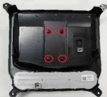
Interior view of an electric vehicle chassis showing battery pack, casing, and mounting points (no text or symbols visible)Step 2
Attach the display to the panel using four M4 x 10 screws from the HEIGH10 hardware pack.
Section Five: Radio Module Preparation
Part One: Radio Module Side Brackets
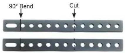
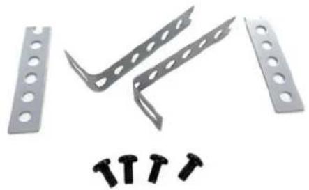
natural_image
Metal bracket with multiple holes and four screws below (no text or symbols)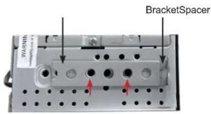
From the HEIGH10 hardware, mark the two metal brackets as shown above. Make a 90° bend at the solid line and cut along the dotted line.
Step 2 Step 1 Step 3
Save the cut off end pieces; they will be used as spacers. From the HEIGH10 hardware, four M5 x 10 screws will be used to attach the brackets.
Align one of the 90° side brackets to the left side as shown. Bracket, then spacer and attach with two M5x10 screws in the locations shown.
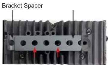
Step 4 Step 5
Align the other 90° bracket to the right side as shown. Bracket, then spacer and attach with two M5x10 screws in the locations shown.
natural_image
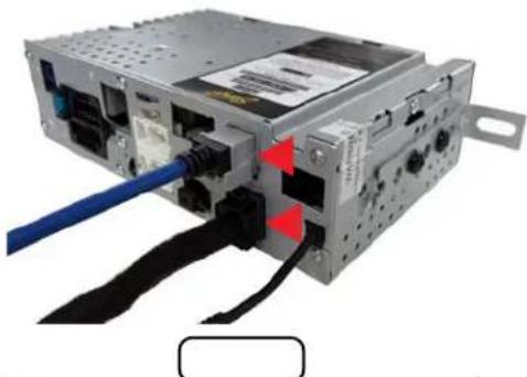
Close-up of a computer drive chassis with blue cable and black connectors (no visible text or symbols)From the HEIGH10 box, connect the LVDS (Blue USB) and 10 pin display cables to the Radio Module.
Section 5: Radio Unit Installation
Part One: In-Vehicle Harness and Cabling Connections
(Step 1A)
natural_image
Close-up of hands holding a white connector with multicolored wires, partially enclosed in an electronic device (no visible text or symbols)Step 1B
natural_image
Interior view of a vehicle showing wiring and components (no visible text or symbols)Step 2
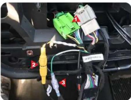
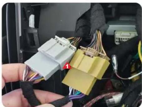
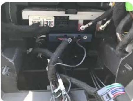
IO3, IO4, IO5, IO6: Connect the Green and Gray vehicle side plugs (1) on the RP5 Main Harness to the matching plugs in the vehicle.
IO4, IO5, IO6: If equipped, connect the Yellow CAM-51 Input RCA to CAMERA RCA (2) and connect the male green/black SWC Input to the female SWC lead (3).
IOB: Connect the Mustard and Gray vehicle side plugs (1) on the RP5 Main Harness to the matching plugs in the vehicle.
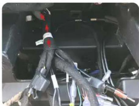
After the two vehicle side plugs are connected, push the connectors back into the rear access hole as far as possible to make room for when the radio module is installed.
natural_image
Interior view of a vehicle showing exposed wiring and components (no visible text or symbols)Step 3
natural_image
Close-up of a car's internal electronic device showing ports, cables, and connectors (no visible text or symbols)Step 4
natural_image
Close-up of a mechanical component with visible wiring and colored components, no readable text or symbols present.Step 5
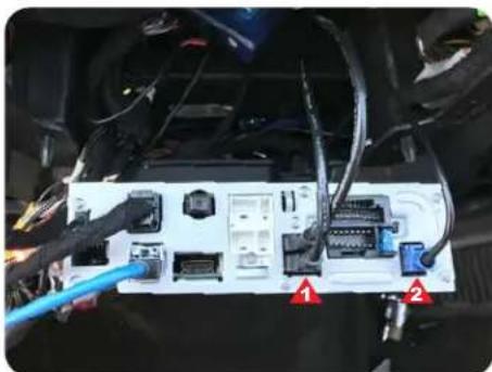
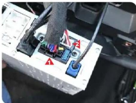
Temporarily place the RP5-GM51 module inside the CD/DVD cavity while making the following connections to the HEIGH10 Radio Module.
Plug in the two USB cables (1) and the GPS antenna (2).
Plug in the HEIGH10's 16 pin Main Harness (1) and 24 pin A/V Harness (2).
Section 5: Radio Unit Installation (cont.)
Part One: In-Vehicle Harness and Cabling Connections (cont.)
natural_image
Close-up of an automotive electrical panel with visible wiring and components (no text or symbols)Step 6
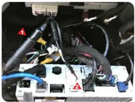
Connect the radio side of BAA22 Antenna Adapter (1) to the HEIGH10's AM/FM antenna input. Plug in the 6 pin SWC / EXT IR harness (2).
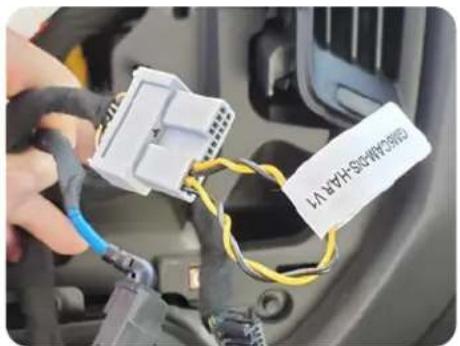
Step 7
2018-19 IOB Only: Plug the 20 pin harness that was removed from the factory display into the GM5CAM-DIS-HAR.
These are the connections for a typical installation. If adding additional cameras, amplifiers or satellite radio, those connections should be made at this point, before mounting the radio module.
Part Two: Radio Unit Mounting
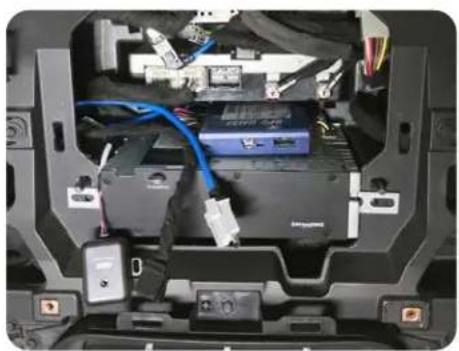
natural_image
Interior view of a laptop case showing internal components including battery pack, cables, and connectors (no visible text or symbols)
With the Chime Module and both display cables routed over the top, place the RP5 interface on top of the radio module and slide it into CD/DVD cavity as noted in Step 2.
natural_image
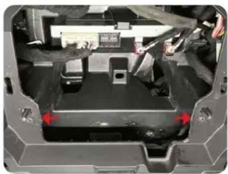
Interior view of a vehicle chassis frame with red arrows indicating specific components (no visible text or symbols)Step 2 Step 1 Step 3
The plastic panel in front of the CD/DVD cavity is narrower than the cavity itself and will prevent the side bracket screws from passing. The side bracket screws will need be angled up and over this panel as it is put in place.
natural_image
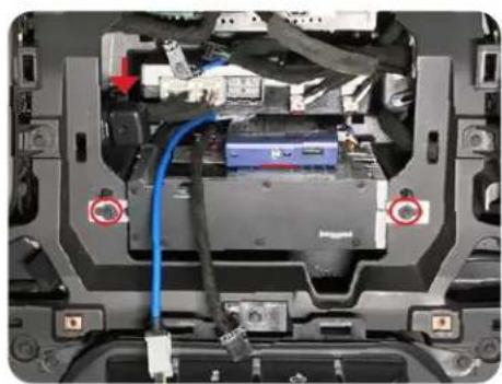
Laptop interior showing internal components with a blue cable and labeled connectors (no readable text or symbols)Once in place, secure the radio assembly with two 7mm screws. Zip tie the Chime Module in a suitable location. Use the supplied two-sided tape to secure the RP5 interface to the top of the radio module.
Section 5: Radio Unit Installation (cont.)
Part Two: Radio Unit Mounting (cont.)
natural_image
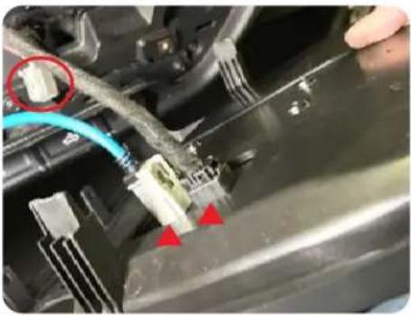
Close-up of a car engine bay with visible wiring and connector components (no text or symbols)Plug the two display cables into the back of the HEIGH10 display. Re-connect the factory climate control connector to the climate controls.

natural_image
Close-up of a hand adjusting a car interior panel with a tool (no visible text or symbols)Step 5 Step 4
Place the mounting panel in place and temporarily secure it with two 7mm screws.
Before reassembly, it is recommended to power up the radio and check the chime volume* and all other functionality...
Volume, Balance, Fade
AM/FM Reception
Bluetooth
USB
Apple Carplay
Android Auto
Camera(s)
* The Chime Module has a 4 position volume selector on the side. Setting 1 being the loudest and 4 being the quietest.
Product Updates (Firmware)
Firmware Updates (RadioPRO)
The RadioPRO PC app will allow you to update the interface modules with new firmware as it becomes available. Please visit www.PAC-audio.com/firmware to download available updates.
To update an interface module, open the RadioPRO PC app, connect the interface to your PC via a micro USB cable, and select "Firmware" and then "Update Firmware".
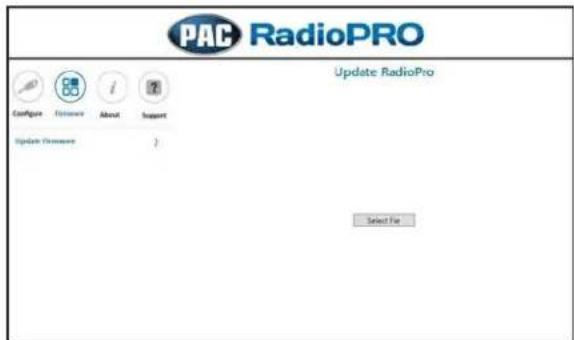
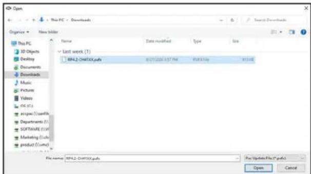
Now, select "Select File". Finally, browse to the place where you saved the file, and select it. This will begin the updating process. Once finished, disconnect the interface from the PC.
Firmware Updates (Stinger Radio and PAC Application APK)
To update the HEIGH10 radio firmware and PAC Application APK firmware, refer to the HEIGH10 product page: www.stingerelectronics.com/products/heigh10
Reset / Restoring Interface Factory Settings
You can restore the RadioPRO interface module to factory default settings by pressing and holding the programming button on the side of the module until the status LED starts blinking red. Once the LED starts blinking red, release the button. You must release the button while the LED is blinking red in order to perform the reset. This reset will restore all settings to factory defaults.
Technical Support
Email: support@PAC-audio.com
Phone: 866-931-8021
International: 727-592-5991
Stinger®
HEIGH10·
10-INCH MODULAR MULTIMEDIA DISPLAY SYSTEM
USER GUIDE
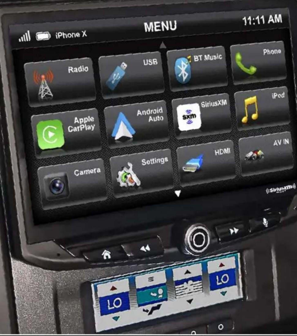

HEIGH10·
WELCOME TO YOUR NEW
Works with Apple CarPlay
androidauto™
((SiriusXM) READY)
Bluetooth®
HDMI®
Apple CarPlay is a trademark of Apple Inc. Use of the Apple CarPlay logo means that a vehicle user interface meets Apple performance standards. Apple is not responsible for the operation of this vehicle or its compliance with safety and regulatory standards. Please note that the use of this product with iPhone, iPod, or iPad may affect wireless performance.
"Made for iPod," "Made for iPhone," and "Made for iPad" mean that an electronic accessory has been designed to connect specifically to iPod, iPhone, or iPad, respectively, and has been certified by the developer to meet Apple performance standards. Apple is not responsible for the operation of this device or its compliance with safety and regulatory standards. Please note that the use of this accessory with iPod, iPhone, or iPad may affect wireless performance. iPad, iPhone, iPod nano, and iPod touch are trademarks of Apple Inc., registered in the U.S. and other countries.
Visit StingerElectronics.com for updates and further detailed information.
TECHNICAL SUPPORT:
800-477-2267
support@aampglobal.com
CUSTOMER SOLUTIONS:
800-477-2267
customersolutions@aampglobal.com
Stinger is a Power Brand of AAMP Global
15500 Lightwave Drive, Suite 202
Clearwater, Florida 33760
SiriusXM and all related marks and logos are trademarks of Sirius XM Radio Inc. All rights reserved.
Android, Android Auto, Google Play and other marks are trademarks of Google LLC.
The Bluetooth word mark and logos are registered trademarks owned by Bluetooth SIG, INC. and any use of such marks by AAMP Global is under license.
HDMI, the HDMI Logo, and High-Definition Multimedia Interface are trademarks or registered trademarks of HDMI Licensing LLC in the United States and other countries
Stinger and the Stinger logo are trademarks or registered trademarks of AAMP Global in the United States and other countries.
AGREEMENT: End user agrees to use this product in compliance with the instructions and terms of use and with all State and Federal laws. STINGER provides instructions and safety warnings with respect to this product and disclaims all liability for any use not in conjunction with those instructions or other misuse of its product. If you do not agree, please discontinue use and contact STINGER. This product is intended for off-road use and passenger use only.

HEIGH10·
Enjoy the ride
CONTENTS
The Basics......4
Getting Started....6
AM/FM Radio....8
Bluetooth Phone....9
Pairing a Device....10
BT Device Settings.....11
Contacts/Call Log.....12
Bluetooth Music....13
SiriusXM ^® 14
SiriusXM Replay™....17
SiriusXM Lock Code.....18
USB Media....19
Apple CarPlay ^® 20
Android Auto™......21
iPod....22
HDMI....23
AV In....23
Cameras....24
Navigation....25
Display Off....25
Settings.....26
Clock....26
System Settings.....26
Illumination....27
Backgrounds.....28
Display....28
Tabs....28
Camera....29
Audio Settings....30
Equalizer....31
Factory EQ....31
Crossover....32
Time Correction....33
Toslink....34
Gain/Volume....34
Reset Button....35
Trouble Shooting....36
Specifications....38
THE BASICS
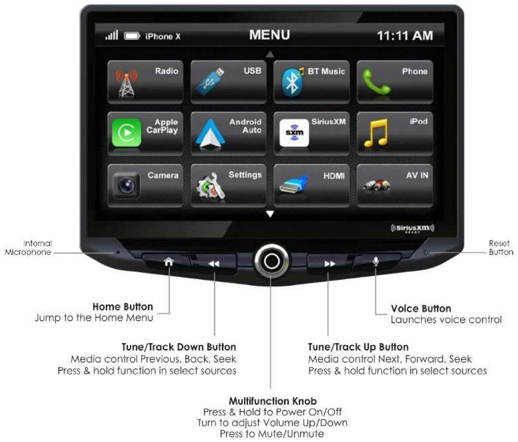

HEIGH10·
GETTING STARTED
POWER UP!
With vehicle ignition in the ON or ACC position, Press and Hold the knob for 2 seconds to power ON/OFF.
The source will automatically default to the last source used prior to powering down.
You can adjust the audio volume at start-up in Sound Settings on page 34.
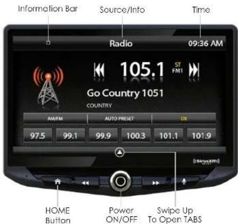
The Information Bar is located at the top of the screen. Depending on the SOURCE, it will provide information or content sensitive controls. Also, displays time, phone info and may contain BACK ARROW and EXIT buttons.
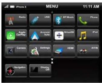
Customizable TABS can be accessed by swiping the up arrow ▲ at the bottom of the screen. Tabs give direct access to sources/settings and can be customized in Settings > Tabs on page 28.
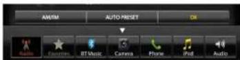
The active Tab will be highlighted and sources that are not available will be dimmed out. Once the Tabs are opened, the will auto-close after 5 seconds or press the down arrow ▼ to close the tabs.
SELECTING A SOURCE
To select a source, press the HOME button.
The HOME MENU displays all Sources, along with Settings, Audio, Display and Camera options.
SOURCES that are not currently available are grayed out.
QUICK TIP
There are multiple ways to scroll... Swipling Up/Down, Up/Down Arrows
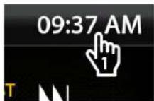
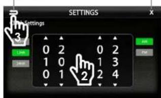
SETTING THE TIME
1) Touch and Hold the Time Display on the Information Bar for 2 seconds to access the clock settings.
2) Swipe or click arrows to set time and format.
3) Touch the BACK ARROW or EXIT to save and exit.
Back Arrow Exit

HEIGH10·
AM/FM RADIO
Bluetooth PHONE
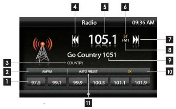
Press the HOME BUTTON > Radio to select the Radio
1 Station Presets - To assign a preset, go to desired station, press and hold a preset location until preset button highlights and station frequency appears. A total of 18 FM and 12 AM stations can be stored in memory.
2 AM/FM - Press to cycle through AM/FM presets (FM1-FM2-FM3-AM1-AM2)
3 PTY Program Type - Indicates radio station type.
4 Tune/Seek Down - Press and release to Tune Down. Press and hold to Seek the next available radio station.
5 Station Display - Displays current frequency.
6 ST Indicator - Indicates when current radio station is in Stereo.
7 Tune/Seek Up - Press and release to Tune Up. Press and hold to Seek the next available radio station.
8 Preset Bank - Indicates current preset bank.
9 RT Info- station/title/artist information
10 DX/LOC - changes the radio tuner sensitivity. Touch to toggle between Distant (DX) and Local (LOC).
11 Auto Preset - Touch to automatically set the 6 presets with current location radio stations.
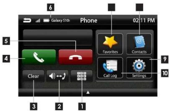
Press the HOME BUTTON > Phone to select the Phone
1 Number Pad - Touch to launch the number pad for dialing phone numbers.
2 Speaker/Phone - Switches phone calls between the car speakers and the phone handset.
3 Clear - Clear/delete last number entered.
4 Call/Answer - Dials the number entered on the phone or on the number pod. Answers incoming call.
5 End/Decline - Press to end active call or decline incoming call.
6 Device Info - Displays the name of the currently paired device, signal strength and battery status.
7 Favorites - Customizable list of favorite contacts.
8 Contacts - List of contacts from paired phone. Not supported by all phones.
9 Settings - List of devices and settings. Add or Delete devices.
10 Call Log - Recent Dialed, Received and Missed calls.

HEIGH10·
Bluetooth PHONE Bluetooth PHONE
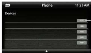
Pairing a Device
1 Select Settings from the Phone main menu to go to BT Device Settings.
2 Select Devices ▶ on the BT Device settings page.
Place your device in Discoverable Mode.
3 Select ADD on the Devices page
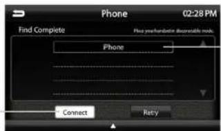
4 Select your device from the list.
NOTE!
If your device does not appear in the device list, confirm it is discoverable and select Retry
5 Select Connect to initiate pairing
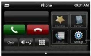
1
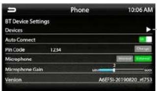
2
3
5
4
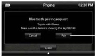
6 Select Pair when prompted.
Confirm Key Code on device and select Pair on device.
If prompted, select Allow to share contacts
6
NOTE!
Once a device is paired, it will automatically connect whenever the system is turned on and the device is within range. To manually connect or connect to a different device go to Phone > Settings > Devices
BT Device Settings
Once a device is paired and connected, settings can be set on the BT Device Settings page.
Devices ▶
Access list of all devices in memory. Connect/Add/Delete devices.
Auto Connect [ON/OFF]
Set to ON if you want the device to automatically connect when the system is turned on.
Pin Code [CHANGE]
Change the pin code for Bluetooth connection. The default pin code is "1234"
Microphone [Internal/External]
Set to External if external microphone is installed. Set to internal to use the microphone located on the front of the display.
Microphone Gain [0-6]
Adjusts the volume (sensitivity) of the microphone when using hands free phone.

![Stinger SR-GM14H - Microphone Gain [0-6] - 2](/content/2026/05/975796/images/66007cc9e15fb00f26a1cb7f652acafe3798f7e42cfe90ba0a909d73228d8ed5.jpg)
HEIGH10·
Bluetooth PHONE
Bluetooth MUSIC
Contacts
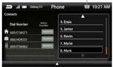
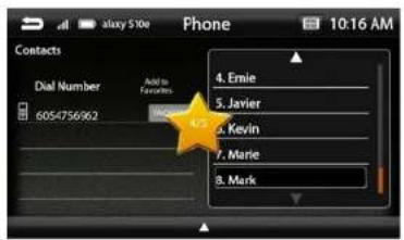
While a device is paired, Contacts can be accessed by selecting Contacts from the Phone main menu. It may take several minutes to load all contacts. When a contact is selected from the list, all associated numbers (Home/Work/Mobile) will be displayed on the left side of the screen. Touch the number you want to dial.
To add a contact number to the Favorites list, touch FAVORITES next to the contact phone number and it will be added to your Favorites list.
The Favorites list can be accessed from the Phone main menu.
To Search your contact list, select the keyboard icon on the Information Bar.
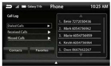
Call Log
The Call Log lists recently Dialed, Received and Missed calls. Touch the contact or phone number to dial a number.
Search Contacts
4
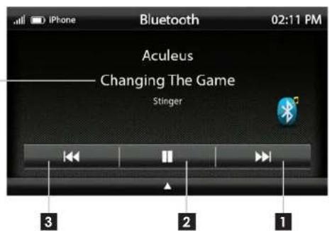
Press the HOME BUTTON > BT Music to select the BT Music source
1 Next Track/Program - Touch to advance to the Next track/Program.
2 Play/Pause - Touch to play or pause the audio.
3 Previous Track/Program - Touch once to restart current track, touch again for Previous track.
4 Song/Program Information - Displays information for the current track.

HEIGH10·
®Satelite Radio (OPTIONAL)
Only SiriusXM brings you more of what you love to listen to, all in one place. Get over 140 channels, including commercial-free music plus the best sports, news, talk, comedy and entertainment. Welcome to the world of satellite radio. A SiriusXM Vehicle Tuner and Subscription are required. For more information, visit www.siriusxm.com
Activating your SiriusXM Subscription
After installing your SiriusXM Connect Vehicle Tuner and antenna, power on your radio and select SiriusXM mode. You should be able to hear the SiriusXM preview channel on Channel 1. If you cannot hear the preview channel, please check the installation instructions to make sure your SiriusXM Connect tuner is properly installed.
After you can hear the preview channel, tune to Channel 0 to find the Radio ID of your tuner. In addition, the Radio ID is located on the bottom of the SiriusXM Connect Vehicle Tuner and its packaging. You will need this number to activate your subscription. Write the number down for reference.
Note: the SiriusXM Radio ID does not include the letters I, O, S or F.
In the USA, you can activate online or by calling SiriusXM Listener care:
- Visit www.siriusxm.com/activatenow
• Call SiriusXM Listener Care at 1-866-635-2349
For Canadian Subscriptions, please contact:
- Visit www.siriusxm.ca/activatexm
• Call XM customer Care at 1-877-438-9677
As part of the activation process, the SiriusXM satellites will send an activation message to your tuner. When your radio detects that the tuner has received the activation message, your radio will display: Subscription Updated. Once subscribed, you can tune to channels in your subscription plan. Note, the activation process usually takes 10 to 15 minutes, but may take up to an hour. Your radio will need to be powered on and receiving the SiriusXM signal to receive the activation message.
SiriusXM Satellite RadioSiri
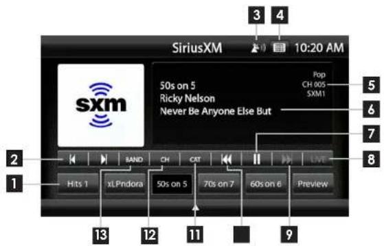
Press the HOME BUTTON > SiriusXM to select the SiriusXM source.
1 Channel Presets - To assign a preset, go to desired channel, press and hold a preset location until preset button highlights and channel name appears. A total of 18 channels can be stored in memory.
2 Channel Down/Up- Touch to go to previous channel / advance to next channel. Touching and holding either button will rapidly browse through the channels.
3 Signal Strength - Displays tuner signal strength, 0-3 bars.
4 Keypad - Touch to display keypad for direct channel number entry.
5 SiriusXM Info - Displays current channel category, channel number and preset bank number.
6 Channel Info- Displays channel name, song/content info.
7 Pause/Play - Pause live broadcast / Play stored audio
8 LIVE- Select to return to live broadcast when listening to stored audio.
9 Fast Forward/Track Up- Move forward through stored audio
10 Rewind/Track Down - Move backwards through stored audio
11 CAT - Touch to display a list of channel Categories.
12 CH - Touch to display a list of available channels with channel information.
13 BAND - Press to cycle through SXM preset banks [SXM1-SXM2-SXM3]

HEIGH10·
SiriusXM Satellite Radio SiriusXM
Satelite Radio
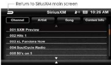
Channels [CH]
Displays a list of available SiriusXM channels in numerical order. Swipe up/down to navigate, touch to select desired channel. Selecting Content Info, Artist or Song buttons will toggle the information displayed.
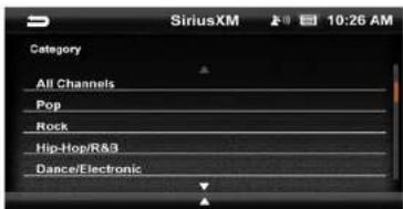
Categories [CAT]
Displays a list of channel categories. When a category is selected, a list of matching channels will display. Selecting All Channels will display all channels in numerical order.
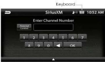
Direct Tuning
Selecting the Keypad Icon on the Information Bar will launch a numeric keypad for direct channel number entry. (See Page 18 for Parental Control function)
SiriusXM Replay™
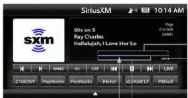
Replay allows you to pause, rewind and replay up to 1 hour of live SiriusXM Satellite Radio.
Pressing Pause or Rewind while listening to a live broadcast will enable Replay mode.
The Replay Time Bar will appear when Replay is active.
When you reach the end of the stored audio buffer, you will return to the live broadcast. Or, touch the LIVE button in the Replay view to return to the live broadcast of the current channel.
Replay Controls
Touch for Previous Song Touch & Hold for Rewind


Touch for Next Song Touch & Hold for Fast Forward
1 2
① Current Replay Point
2 Buffer Range (Light Blue line)
3 Replay Range
4 Time to Live
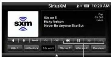
Replay Controls

HEIGH10·
SiriusXM Satellite Radio
USB Media
Parental Control
The SiriusXM Parental Control feature allows you to prevent access to inappropriate mature content for a younger listener. When enabled, the Parental Control feature requires you to enter a passcode to access the channels that are rated as Mature Channels.
By default, all channels are Unlocked and the Lock Code is 1234
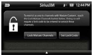
Lock Mature Channels:
- Touch the Keyboard icon on the Information Bar.
- Touch the Parental Control button.
- Select Lock Mature Channels
- Enter 4 digit lock code.
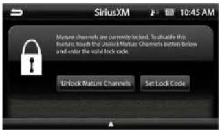
Unlock Mature Channels:
- Touch the Keyboard icon on the Information Bar.
- Touch the Parental Control button.
- Select Unlock Mature Channels
- Enter 4 digit lock code.
Set/Change Lock Code:
Select Sel Lock Code, enter old code and then enter new code.
Reset Lock Code:
To reset the Lock Code to default code (1234) Go to System Settings > Load Defaults. The reset process takes 5-7 minutes and will reset ALL saved settings to factory default.
Keyboard Icon
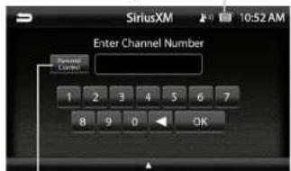
Parental Control

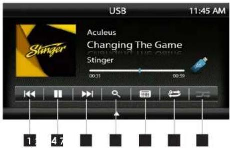
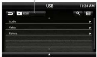
With a USB drive plugged in - press the HOME BUTTON > USB to select USB.
From the USB Root Menu you can browse Audio, Video and Image files. See page 39 for a list of supported file types.
Touch to select a file to view/play.
1 Previous Track - Touch once to restart current track, touch again for Previous track.
2 Play/Pause - Touch to play or pause the audio.
3 Next Track - Touch to advance to the Next track.
4 Browse - browse artist, album or songs.
5 Keyboard - direct input song search
6 Repeat - Press once to repeat the current track (1), press again to repeat album/folder (F).
7 Shuffle - Plays tracks in random order.
USB Root Menu
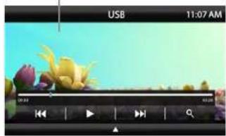
Video / Image Files

HEIGH10·
Apple CarPlay®
Set up Apple CarPlay
You can use Apple CarPlay to get directions, make calls, send and receive messages, and more.
You need an iPhone 5 or later to use Apple CarPlay. Also, make sure that you're in an area that supports Apple CarPlay and that Siri is on. To turn on Siri on your phone, go to Settings > Siri & Search.
With the your vehicle running, plug your iPhone into the Apple CarPlay USB port. Apple CarPlay will launch automatically.
If your iPhone is already plugged into the USB, press the HOME BUTTON > Apple CarPlay to launch Apple CarPlay.
NOTE: If Apple CarPlay will not launch, see Troubleshooting.
The display will show available apps. Only apps that are supported by Apple CarPlay will appear.
To add, remove, or customize the order that the apps are in on your iOS device:
-
Go to Settings > General, and tap CarPlay.
-
Select UN1880
-
Select Customize
-
Use the add or delete icons to add or remove apps. Tap and drag an app to change the icon order.
To exit Apple CarPlay, press the Slinger Main Menu icon.
For details about Apple CarPlay, visit https://support.apple.com/en-us/HT205634
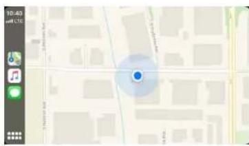
CarPlay Home
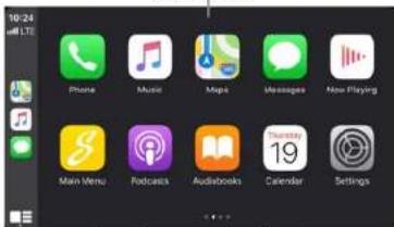
Toggle CarPlay Home / Dashboard
CarPlay Dashboard
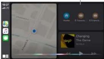
Press & Hold for Siri

Ask Siri for what you need. Press the Voice Control button or The Home/
Dashboard button in Apple CarPlay until Siri appears on the display, then say what you need.
Make sure your phone is running Android 5.0 (Lollipop) or later. Download the Android Auto app from Google Play on your device. Once the app is installed, open the app and follow the setup steps.
Connect your phone
Before you connect your phone for the first time, turn on your car. Make sure it's in park (P) and that you have time to set up Android Auto.
-
Unlock your phone's screen.
-
Connect your phone using a USB cable.
-
Your phone might ask you to download or update certain apps, like Google Maps.
-
Review the Safety Information and Android Auto permissions to access your apps.
-
Tum on notifications for Android Auto. For the best experience, we recommend accepting all requests.
Your phone's Bluetooth will be turned on automatically when Android Auto is connected to the car via USB.
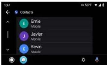
To exit Android Auto, touch the Exit icon.
For details about AndroidAuto, visit https://www.android.com/auto/
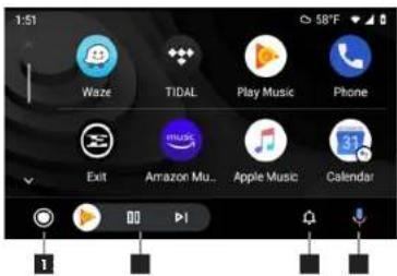
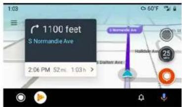
1 Home Button
2 Audio Controls
3 Notifications
4 Voice Command

HEIGH10·
iPod®
HDMI INPUT
Press the HOME BUTTON > HDMI to switch to the HDMI input.
The HDMI input can be used for an external DVD player, streaming sticks, media players, smartphone mirroring.
You can only view HDMI content with the vehicle in Park and the parking brake ON.
When viewing HDMI content, the Information Bar will auto-hide. To access the Information Bar, touch anywhere on the screen.

natural_image
Scenic river landscape at dusk with hills and bridge, no visible text or symbolsAV IN
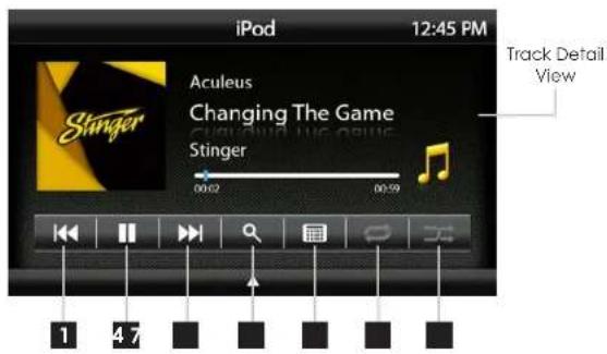
Press MENU > iPod to select iPod as the source.
1 Previous Track - Touch once to restart current track, touch again for Previous track.
2 Play/Pause - Touch to play or pause the audio.
3 Next Track - Touch to advance to the Next track.
4 Browse - browse artist, album or songs.
5 Keyboard - direct input song search
6 Repeat - Press once to repeat the current track (1), press again to repeat album/folder (F).
7 Shuffle - Plays tracks in random order.
iPod Root Menu
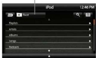
Return to Track Detail View
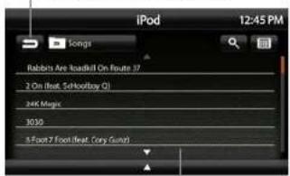
Browse and Select by
Artists, Albums, Playlists, Songs...
Press the HOME BUTTON > AV IN to switch to the AV input.
You can only view the AV input with the vehicle in Park and the parking brake ON.
When viewing the AV IN, the Information Bar will auto-hide. To access the Information Bar, touch anywhere on the screen.
WARNING!
Driver is prohibited by law from viewing a video signal on any In-dash monitor while the vehicle is in motion.

HEIGH10·
CAMERAS
Press the HOME BUTTON > Cameras to access Cameras
If there are optional cameras installed, you may view them at anytime using the camera selection bar at the bottom of the screen.
To Exit camera view, touch the Back Arrow.
Note: For Irigerred side cameras that turn on automatically with the turn signals, you can override and close the camera view by touching the screen.
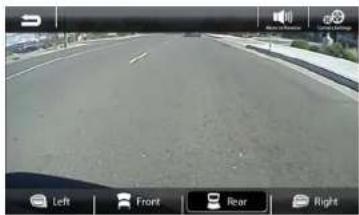
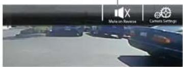
Mute On Reverse
The Mute on Reverse feature will mute all audio while in Reverse, touch the speaker icon to toggle between mute ON/OFF.
Settings > Camera Settings
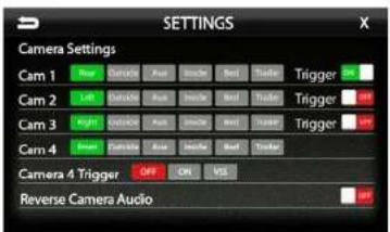
Cam1-4 Label
[REAR-OUTSIDE-AUX-INSIDE-BED-TRAILER] Allows custom labeling for multiple cameras
Cam 1-3 Trigger [ON-OFF]
Set individual camera triggers ON/OFF
Cam 4 Trigger [ON-OFF-VSS]
Set Camera 4 trigger ON, OFF or Vehicle Speed Sense.
Use VSS Mode when parallel parking aid is desired (front camera and VSS wire need to be connected).
On VSS Mode, the front camera will turn on after shifting from Reverse gear and remain On until the speed reaches above SMPH or the display is touched.
Reverse Camera Audio [ON-OFF]
When set to ON and a microphone is connected, back up camera audio will be heard through the vehicle's speakers.
natural_image
Front view of a highway with navigation controls (Left, Front, Rear, Right) and vehicle icons on the road (no readable text or symbols)Mute On Reverse Active



iGO NAVIGATION
(OPTIONAL)
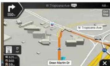
To access the optional Navigation, press the NAVIGATION BUTTON on the side of the display or press the HOME BUTTON >Navigation
The User Manual for iGO Navigation can be found on StingerElectronics.com
To add navigation, ask your dealer about Stinger's pre-loaded iGO Navigation SD Card (Part Number: SE-P14).
Press the HOME BUTTON > Display Off to turn off LCD.
This is useful at night to prevent eye fatigue.
Tap the screen anywhere to return to regular display.
DISPLAY OFF

natural_image
Completely black image with no visible content or text.
HEIGH10·
SETTINGS
SETTINGS
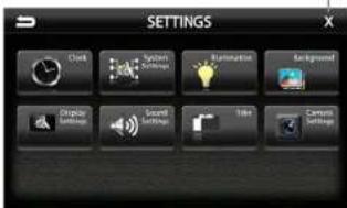
Press the HOME BUTTON > Settings
to access the Settings main menu.
Clock
System Settings
Illumination
Background
Display Settings
Sound Settings
Tabs
Camera Settings
EXIT current screen
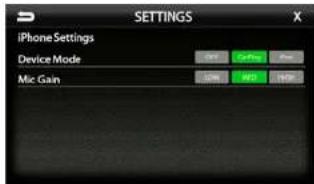
Settings > System Settings > Apple CarPlay
Device Mode [OFF-CarPlay-iPod]
Determines how iPhone will be used when plugged into USB port. OFF is charging only
Mic Gain [LOW-MED-HIGH]
Sets microphone gain (sensitivity) when using Apple CarPlay.
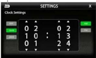
Settings > Clock
Clock Settings [OFF-12HR-24HR]
Select time format. Swipe or click answers to set time.
-BACK to previous screen
Settings > System Settings > Android Auto
Android Auto [ON-OFF]
Set to OFF for charging only with Android devices.
Auto Launch [ON-OFF]
When set to ON, Android Auto will automatically launch when compatible Android device is plugged into USB port.
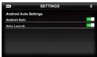
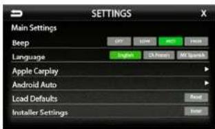
Settings > System Settings
Beep [OFF-LOW-MED-HIGH]
Sets volume of confirmation beeps.
Language [ENGLISH FRENCH SPANISH] Set display language
Apple CarPlay [See Page 27]
Android Auto [See Page 27]
Load Defaults [RESET]
Selecting Reset will reset all settings to factory defaults. This process takes 5-7 minutes and system must NOT be shut down during the reset.
Installer Settings [ENTER]
See Installation Guide or Firmware Update
Instructions for more information.
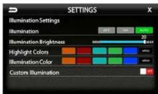
Settings > Illumination
Illumination[OFF-ON-AUTO]
Turn button illumination ON/OFF. Set to AUTO for buttons to illuminate only when vehicle lights are on.
Illumination Brightness[0-20]
Set brightness of button illumination
Highlight Colors
[AMBER-RED-AQUA-GREEN-BLUE-WHITE] Set on-screen highlight color.
Illumination Color
[AMBER-RED-AQUA-GREEN-BLUE-WHITE] Set button illumination color.
Custom Illumination [OFF-ON]
When Custom illumination is set to ON, allows custom illumination color based on RGB values.
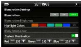
Stinger
HEIGH10·
SETTINGSSE1
Settings > Background
Allows you to change the background image. Touch image thumbnail to select. You can upload up to 3 of your own images. To upload an image(s), copy images onto a USB thumb drive and connect drive to one of the USB ports. Touch the @ symbol and select file. Images should be JPG or PNG file format and 1024*600 resolution
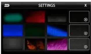
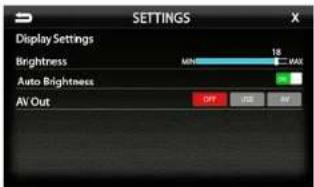
Settings > Display Settings
Brightness [0-20]
Adjust Day and Night brightness of LCD display. To adjust Night brightness level, turn on vehicles lights and then adjust brightness.
Auto Brightness [ON-OFF]
When set to ON, display screen will automatically dim when vehicle lights are turned on.
AV [OFF-USB-AV]
Determines which source is routed to the AV outputs.
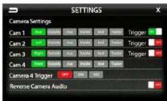
Settings > Camera Settings
Com1-4 Label
[REAR-OUTSIDE-AUX-INSIDE-BED-TRAILER] Allows custom labeling for multiple cameras
Cam 1-3 Trigger [ON-OFF]
Set individual camera triggers ON/OFF
Set Camera 4 Trigger ON, OFF or Vehicle Speed Sense.
Use VSS Mode when parallel parking aid is desired (front camera and VSS wire need to be connected).
On VSS Mode, the front camera will turn on after shifting from Reverse gear and remain On until the speed reaches above 5MPH or the display is touched.
Reverse Camera Audio [ON-OFF]
When set to ON and a microphone is connected, back up camera audio will be heard through the vehicle's speakers.
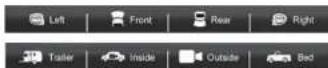

Settings > Tabs
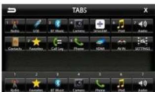
The Tabs are customizable and can be configured to include favorite sources or settings.
To Program a Tab:
1) Select a Tab position (1-7) on the bottom row 2) Select the desired source or setting from the options on the top rows.

HEIGH10·
SOUND SETTINGS
SOUND SETTINGS
4
Settings > Sound Settings
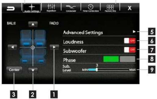
Balance [-9 - 0 - 9]
Using the Left and Right arrows, adjusts the speaker balance Left/Right.
2 Fader [-9 - 0 - 9] Using the Up and Down arrows fades the speakers Front/Rear.
3 Center Press to set balance and fade to zero (0)
4 Audio Menu Bar Access to Equalizers, Crossovers and Time Correction
5 Advanced Settings
Access to gain/volume settings. Toslink, microphone settings. (See page 34)
6 Loudness [ON-OFF]
When ON, boosts low and high frequencies when listening at lower volume
7 Subwoofer [ON-OFF]
Turns subwoofer output ON/OFF
8 Phase [0°-180°] Changes phase of subwoofer signal.
9 Sub Level [0-15] Adjusts volume level of subwoofer output.
Sound Settings > Equalizer
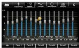
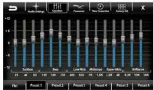
Selecting Equalizer from the Audio Menu Bar will bring up the 15 band graphic equalizer and presets. Frequency adjustments can be made by touching and sliding the frequency sliders up/cown. Once the desired sound is achieved, it can be saved as a Preset.
Saving EQ Settings
There are 6 user Presets that can be used to save EQ settings. This is useful for having EQ settings for different types of music, volume levels or for different sources.
When you are done adjusting the EQ, touch and hold a Preset location to save the settings. The Preset will highlight.
Sound Settings > Factory EQ
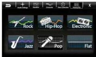
Selecting Factory EQ from the Audio Menu Bar will access factory equalizer presets for different music types.
Rock - Hip-Hop - Electronic - Jazz - Pop
When a Factory EQ preset is selected, it can be fine-tuned using the Equalizer and then re-saved as a User Preset.

HEIGH10·
SOUND SETTINGS SOUND SETTINGS
Sound Settings > Crossover
Selecting Crossover from the Audio Menu Bar will access the internal electronic variable crossover. Crossover settings can be saved and recalled via Presets.
Front / Rear / Subwoofer Channels Select Front, Rear or Subwoofer to set crossover.
Slope [6dB-12dB-18dB]
Adjusts the slope of the crossover.
Frequency
[BYPASS-25-40-63-80-100-160-250Hz] Adjusts crossover frequency. Front and Rear channels are High Pass and Subwoofer is Low Pass.
Level [-12 - 0]
Adjusts signal level. Channel levels can be adjusted regardless of crossover settings.
Saving Crossover Settings
There are 6 user Presets that can be used to save Crossover settings.
When you are done adjusting the Crossover, touch and hold a Preset location to save the settings. The Preset will highlight.
Graphical representation of crossover Slope, Frequency and Level.
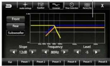
Front Channel = Blue Rear Channel = Orange Subwoofer = Green Active(Selected) = Yellow
Sound Settings > Time Correction
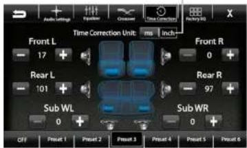
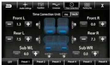
Selecting Time Correction from the Audio Menu Bar will access the Time Correction settings. Time Correction settings can be saved and recalled via Presets.
Time Correction compensates for the uneven distances between the speakers and a listeners ears. Time Correction delays signals from the closest speaker(s), so that all the sound arrives at the listening position at the same time, giving the listener a more accurate, life like stereo image.
To set Time Correction, select a listening position, for example the drivers seat headrest. Then measure from each speaker to the listening position. Set Units to inch and input speaker distance values into the appropriate positions using the +/- buttons.
Saving Time Correction Settings
There are 6 user Presets that can be used to save settings. When you are done adjusting the Time Correction, touch and hold a Preset location to save the settings. The Preset will highlight.
Select milliseconds or inches

HEIGH10·
SOUND SETTINGS
Settings > Sound Settings > Advanced Settings
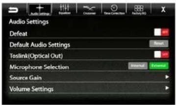
Selecting Advanced Settings ▶ from the Audio Settings screen will access the following settings:
Defeat [ON-OFF]
When set to ON, this will defeat/bypass all equalizer, crossover, speakers settings. This is useful when connecting to a DSP.
Default Audio Settings [Reset] Press to reset all audio settings to default.
Toslink(Optical Out) [ON-OFF]
Turns variable digital output ON/OFF
Microphone Selection [INTERNAL-EXTERNAL] Select External if external microphone is installed. Select internal to use built-in microphone.
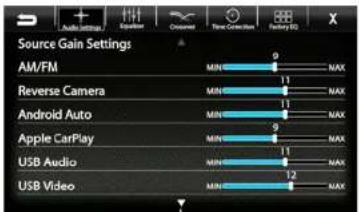
Source Gain Settings ▶
Selecting Source Gain from the Advanced Audio Settings will allow gain/volume adjustments for individual sources. For example, if AM/FM is much louder than BT Music, lower AM/FM and/or raise BT Music to even out volume levels.
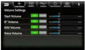
Volume Settings ▶
Selecting Volume Settings from the Advanced Audio Settings will access the following Volume settings:
Arrow down for additional sources
Start Volume [LAST-CUSTOM]
LAST will be same level as when unit was shut off. CUSTOM will be a preset level adjusted below.
Volume Slider [0-40]
Adjusts CUSTOM volume level to specific level.
The Volume Mode is adjustable for Bluetooth(BI). Navigation(NAV) and Voice using the same procedure.
Reset Button
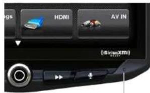
The Reset Button is located on the lower right hand corner of the display. To reset the unit the power must be on, use a paper clip or similar to push the reset button for 2 seconds and release. The reset will take a few minutes, do not turn of power during this time.
Reset Button

HEIGH10·
TROUBLE SHOOTING
Black Screen with Audio
Touch the screen anywhere as it may have been turned off, see page 25. Ensure the cables on the back of the screen are fully locked into place and also properly connected at the back of the radio module. Check for damaged/kinked cables.
Display Image Is Inverted
Press and Hold the HOME BUTTON for 5 seconds. The Display Orientation page will appear, select desired orientation.
Bluetooth
Device will not Pair
Ensure Bluetooth is turned ON in your device settings. Delete all unused devices. Delete any "Slinger" device. Restart/Reboot device and try pairing again. (Page: 10)
Music Volume is low
- Turn up volume on device
- Tum up volume on head unit.
- Turn up BT Volume Gain (Page: 34)
Phone Volume is low
- Tum up volume on device
- Tum up volume on head unit.
- Tum up BT Volume Gain (Page: 34)
- Tum up Mic Gain (Page: 11)
Video/Cameras
Rear Camera not displaying in reverse - Make sure rear camera trigger is ON (Page: 29)
- If display is showing NO SIGNAL in reverse, ensure camera RCA is plugged into correct RCA input (CAMERA IN).
- Confirm camera has power and ground.
- Confirm camera trigger is receiving positive12V.
Note: NTSC and PAL video formats only.
SiriusXM Satellite RadioGene
Check Antenna
The radio has detected a fault with the SiriusXM antenna. The antenna cable may be either disconnected or damaged. - Verify that the antenna cable is connected to the SiriusXM Connect Vehicle Tuner. - Inspect the antenna cable for damage and kinks.
Replace the antenna if the cable is damaged. SiriusXM products are available at your local car audio retailer or online at www.shop.siriusxm.com.
Check Tuner
The radio is having difficulty communicating with the SiriusXM Connect Vehicle Tuner. The tuner may be disconnected or damaged. - Verify that the SiriusXM Connect Vehicle Tuner cable is securely connected to the radio.
No Signal
The SiriusXM Connect Vehicle Tuner is having difficulty receiving the SiriusXM satellite signal.
- Verify that your vehicle is outdoors with a clear view of the sky.
- Verify that the SiriusXM magnetic mount antenna is mounted on a metal surface on the outside of the vehicle. - Move the SiriusXM antenna away from any obstructions. Inspect the antenna cable for damage and kinks.
- Consult the SiriusXM Connect Vehicle tuner installation manual for more information on antenna installation.
Replace the antenna if the cable is damaged. SiriusXM products are available at your local car audio retailer or online at www.shop.siriusxm.com.
Channel Locked
The channel that you have requested is Locked by the radio Parental Control feature. See the Parental Control section on Page 18 for more information on the Parental Control feature and how to access locked channels.
Subscription Updated
The radio has detected a change in your SiriusXM subscription status.
- Press anywhere on the screen to clear the message.
In the U.S.A., visit www.siriusxm.com or call 1-866-635-2349 if you have questions about your subscription. In Canada, visit www.siriusxm.ca or call 1-877-438-9677 if you have questions about your subscription.
Channel Unavailable
The channel that you have requested is not a valid SiriusXM channel or the channel that you were listening to is no longer available. You may also see this message briefly when first connecting a new SiriusXM Connect Vehicle tuner.
Visit www.sinusxm.com for more information about the SiriusXM channel lineup. title, exists.
Memory End
This message will display when the beginning of stored audio has been reached. You cannot rewind any further.
Memory Full
The stored audio memory has become full while audio was paused. Resume playback.
Channel Unsubscribed
The channel that you have requested is not included in your SiriusXM subscription package or the channel that you were listening to is no longer included in your SiriusXM subscription package.
In the U.S.A., visit www.siriusxm.com or call 1-866-635-2349 if you have questions about your subscription package or would like to subscribe to this channel. In Canada, visit www.siriusxm.ca or call 1-877-438-9677.
TROUBLE SHOOTING
Apple CarPlaySiriusXM Satellite
Apple CarPlay will not start/launch
- Ensure you are using a Apple certified cable
- Make sure you are plugged into USB #1(top)
- Make sure Apple CarPlay is turned ON (Page 20)
Android Auto
Android Auto
- Ensure you are using a USB certified cable
- Make sure Android Auto app is
downloaded and installed on your device.
- Make sure you are plugged into USB #1(top)
- Make sure Android Auto is turned ON (Page 21)

HEIGH10·
SPECIFICATIONS SPECIFICATIONS
GENERAL
Operating Voltage: 9.0VDC to 18VDC
Grounding system; Negative Ground
Max current consumption; 10A fused
DIMENSIONS
Radio Module:
178 mm x 100 mm x 116 mm (W x H x D)
Display:
247.2 mm x 180.6 mm x 48.5 mm (W x H x D)
DISPLAY
10-inch Diagonal
16:9 aspect ratio
1024×600
Pixels: 1,843,200
Active area 222.72 (W) x 125.28 (H) mm
Operating Temperature (C) -20° to 70°
AUDIO
Peak power output: 50W x 4ch/4Ω
Load impedance: 4Ω nominal / 2Ω allowable
Continuous power output:
25W x 4ch/4Ω 20Hz to 20KHz,
1%THD of 14.4V
Audio output level (max): 4.0V preout
EQ: (15-band)
25Hz/40Hz/63Hz/100Hz/160Hz/250Hz/400Hz/
630Hz/1KHz/1.6KHz/2.5KHz/4KHz/6.3KHz/
10KHz/16KHz
Gain: ±12dB (2dB/slep)
HPF: 25Hz/40Hz/63Hz/80Hz/100Hz/160Hz/250Hz
Slope: 6dB, 12dB, 18dB
AUDIO (CONT)
Subwoofer Preout
LPF: 25Hz/40Hz/63Hz/80Hz/100Hz/160Hz/250Hz
Slope: 6dB, 12dB, 18dB
Gain: -14dB to 7dB (1dB/step)
Phase: 0 or 180
Speaker level: ±9dB (1dB/slep)
Time Alignment: 0 to 133 step (inch/ms)
USB
USB 2.0
Max current supply 1.5A
USB Class:
MSC (Mass Storage Class),
MTP (Media Transfer Protocol)
File system: FAT32, NTFS
BLUETOOTH
V4.2 dual
4dBm Class2
2.4GHz to 2.48GHz
FM TUNER
87.9MHz to 107.9MHz
Usable sensitive 0dB (mono S/N: 30dB)
SNR: 65dB
AM TUNER
530KHz to 1710KHz
Usable sensitive 0dB (mono S/N:20dB)
SNR 58dB
CAMERA(S) VIDEO INPUTS
NTSC OR PAL video formats
HDMI INPUT
Supported HDMI Resolutions:
640*480p, 720*480p, 1280*720p,
1920*1080i, 1920^1080p
TOSLINK (OPTICAL)
Output: 48khz Variable
BACKGROUND IMAGE (USER)
File Format: JPG / PNG
Resolution: 1024 x 600
File size is not limited
AUDIO/VIDEO FORMATS
AUDIO
MPEG-1 Audio Layer-3 (.mp3)
FLAC (.flac)
MPEG-2 Advanced Audio (.aac)
MPEG-4 Audio (.m4a)
Windows Audio (.wav)
OGG Audio (.ogg)
VIDEO
QuickTime (.mov)
MPEG-4 Video (.mp4)
Microsoft AVI (.avi)
MPG Video (.mpg)
MPEG Video 1/2 (.mpeg)
VOB DVD (.vob)
Flash Video (.lv)
IMAGE
JPEG (.jpg)
CompuServe GIF (.gif)
PNG (.png)
JPEG (jpeg)
Bitmap (.bmp)
ELEV8·
FEATURES
■ 10-Inch 1024 x 600 HD Digital Touchscreen with 16.7M colors
Apple CarPlay®
Google Android Auto™
SiriusXM-Ready® with Replay (SiriusXM Connect Vehicle Tuner and Subscription required)
■ AM/FM Radio - PTY / RT information
■ High power 4 x 50W (peak) built-in amplifier
■ 4V 6ch RCA audio outputs with subwoofer control
■ Toslink (Optical) Variable Audio Output
■ 15 Band Adjustable EQ with 6 user presets
■ 1 HDMI rear input
■ 2 USB rear inputs 1.5amp output
- Handsfree Bluetooth® 4.2 A2DP with aptX™
■ Built-in MicroSD card slot for optional iGO Navigation
■ 4 Camera Video inputs with wired triggers
■ Rear camera input with Mic Audio input
■ Hardwired remote control ready
- Customizable display backgrounds
■ Shallow 1-DIN chassis mounting design
INSTALLATION GUIDE
10-INCH MODULAR MULTIMEDIA DISPLAY SYSTEM
MODEL NUMBER: UN1810
natural_image
Technical line drawing of an electronic device assembly showing internal components and housing (no text or labels)
PRECAUTIONS
Installation of this product requires technical skill and experience. It is recommended to have it professionally installed by an authorized Stinger / Phoenix Gold / PAC / Best Kits Dealer.
Read entire instructions thoroughly before starting.
Disconnect the vehicle's negative battery cable before making any wire connections.
Protect all vehicle surfaces with tape or plastic
Do not install components in any location that will hinder vehicle operation, such as steering wheel, gearshift, air bags, hazard switch.
All wiring should be secured away from sharp edges and moving parts.
Visit StingerElectronics.com for User Guide | Install Guides | Updates | Tech Tips
TECHNICAL SUPPORT:
727-592-5991
Mon-Fri 9AM-8PM EST
Sat 9AM-7PM EST
support@aampglobal.com
CUSTOMER SOLUTIONS:
800-477-2267
Mon-Fri 9AM-8PM EST
customersolutions@aampglobal.com

Slinger is a Power Brand of AAMP Global
15500 Lightwave Drive, Suite 202
Clearwater, Florida 33760
AGREEMENT: End user agrees to use this product in compliance with the instructions and terms of use and with all State and Federal laws. STINGER provides instructions and safety warnings with respect to this product and disclaims all liability for any use not in conjunction with those instructions or other misuse of its product. If you do not agree, please discontinue use and contact STINGER. This product is intended for off-road use and passenger use only.
MODEL NUMBER: UN1810

INSTALLATION GUIDE
CONTENTS
Contents....3
Parts List....4
Hardware Guide....5
Pre-Assembly....6
Display Assembly....7
Mounting Options....7
Double DIN Dash Kit Mounting....8
Double DIN Sub-Dash Kit Mounting.....10
Double DIN Factory Bracket Mounting.....12
Single DIN Dash Kit Mounting....14
Final Assembly....16
Wiring & Connections....17
Dimensions....21
Troubleshooting....22
Upgrades/Options....23
Parts List
| QTY DESCRIPTION PART NO | ||
| 1 Touch Panel Display UN1810-D | ||
| 1 Radio Module UN1810-M | ||
| Mounting Brackets / Hardware | ||
| 1 Plastic Dash Mounting Bracket | PSE-1000 | |
| 1 Display Mounting Clamp | ||
| 1 Metal Mounting Bracket | ||
| 1 Horizontal Display Angle Plate | ||
| 1 Rubber Boot PSE-1001 | ||
| 4 M4 X 6 Screw | PSE-1002 | |
| 4 M4 X 10 Screw | ||
| 4 M4 X 12 Screw | ||
| 2 M4 X 14 Screw | ||
| 2 M4 x 18 Screw | ||
| 6 M5 x 10 Screw | ||
| 6 #10 x 3/8 Screw | ||
| 2 Backstrap SE-1003 | ||
| Cables / Harnesses | ||
| 1 8 Pin Display Power Harness - 18in PSEH-1100 | ||
| 1 LVDS Display Video Cable - 18in PSEH-1101 | ||
| 1 16 Pin Power / Speaker Harness PSEH-1102V2 | ||
| 1 24 Pin AV / Rear Camera Harness PSEH-1103V2 | ||
| 1 10 Pin Multi Camera Harness PSEH-1104V2 | ||
| 1 6 Pin SWI / IR Harness | PSEH-1105V2 | |
| 1 | 4 Pin Mic / Comera Audio Harness | PSEH-1106V2 |
| 1 SiriusXM Cable | PSEH-1107V2 | |
| 1 External Microphone | PSEH-1108 | |
| 1 GPS Antenna & Mounting Plate | PSEH-1109 | |
Optional Accessories (SOLD SEPARATELY)
| DESCRIPTION | PART NO | |
| IR Remote Control | SE-1500 | |
| 8 Pin Display Power Harness - 5FT SE-1501 | ||
| LVDS Display Video Harness - 5FT | SE-1502 | |
| PAC Dash Mount HDMI & USB Extension - 3FT | HDMI-USB-CBL | |
| PAC Dash Mount USB Adapter - 3FT/6FT | USDMA3 / USBDMA6 | |
| Single DIN Mounting Kit | SE-SDIN | |
| Flush Mount Display Housing | SE-HFDK | |
| iGO Navigation North American Map [Micro SD Card] | SE-P14 | |
Hardware Guide
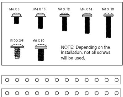
Note: The 2 Backstrap (SE-1003) can be used in some applications to add additional support or used in custom installations. The backstrap may mount to the sides of the radio chassis using the provided screws in the existing mounting locations or can be mounted directly to the Plastic Dash Mounting Bracket.

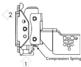
Remove the clamp assembly from the plastic mounting bracket by pushing up from compression spring side (1) and swing out to unhook top (2).
2 Pre-Assembly
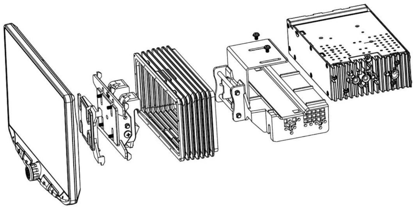
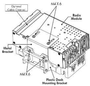
Double DIN Applications: Attach the Metal Bracket to the Plastic Dash Mounting Bracket using M4 X 6 screws. Attach metal bracket and plastic dash mounting bracket assembly to the Radio Module using M4 X 6 screws.
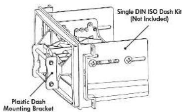
Single DIN Applications: For Single DIN installations, the Plastic Dash Mounting Bracket will be mounted in the dash kit the dash kit and the Radio Module will be mounted remotely. Before beginning the installation, determine where the Radio Module will be installed and make sure the Display Cables are long enough. Longer, 5 foot cables are available (SE-1501 & SE-1502).
3 Display Assembly
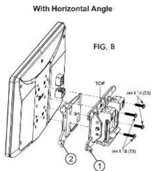
The display can be installed Flat or with a Horizontal Angle towards the driver. For flat mounting, attach the Clamp Assembly (1) to the display using M4 X 14 screws (FIG. A). If a horizontal angle is desired, insert the Angle Plate (2) in between the clamp and display and replace 2 of the M4 X 14 screws with longer M4 X 18 screws on the thicker side of the angle plate (FIG. B). Center the bracket on the back of the display as a starting point, and if needed you can adjust up or down.
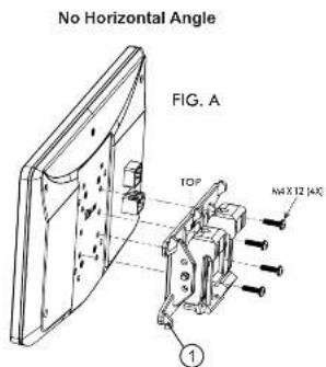
Always ensure TOP indicator on the Clamp Assembly is facing UP.
Multiple Mounting Options
HEIGH10 can be configured for different mounting applications:
4A Using a Double DIN Dash Kit (PAGE 8)
4B Using a Double DIN Sub-Dash Kit (PAGE 10)
4C Using a Double DIN Factory Radio Mounting Brackets (PAGE 12)
4D Using a Single DIN ISO Mountable Dash Kit, relocating Radio Module (PAGE 14)
? Custom Mounting Applications.
See Stinger website for TECH TIPS on vehicle specific installations.
4A
Using a Double DIN Dash Kit:
Radio chassis mounts to the brackets attached to the kit main frame
Display Adjustment & Mounting:
- Install the dash kit side brackets to the main frame.
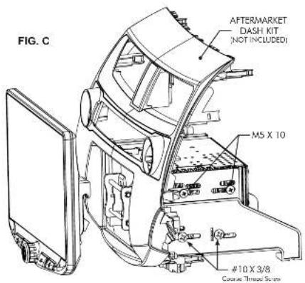
- Making sure to use all 8 screws, loosely attach the radio module & mounting bracket assembly to the side kit brackets (FIG. C).
a. (4x) #10 X 3/8 screws for the plastic mounting bracket locations
b. (4x) M5 X 10 or (4x) M4 X 10 screws for the radio module locations (use any combination of screws to locate the radio in the best position)
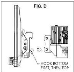
- Attach the display to the bracket assembly by hooking bottom spring hook and then pushing up and hooking top hooks. (FIG. D)
NOTE: BOOT AND DASH KIT NOT SHOWN
8
- Determine the desired position of the display:
a. Display can be vertical or tilted up (FIG. E)
b. Display can slide up or down (Page 7)
c. Display can be tilted horizontally (Page 7 - FIG. B)
Note: There are multiple mounting holes on the mounting bracket to allow adjusting the mounting depth. You may drill additional holes in the mounting bracket and/or the dash kit brackets to align the display in the best position and ensure you can use all 8 mounting screws. - Once in the desired position, tighten screws to the radio chassis (top) and mounting bracket assembly (bottom).
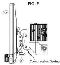
Note: If the display prevents the factory dash panel(s) from being installed last, do not push the display all the way up against the dash kit. Leave enough bottom gap as the display's bottom edge rotates towards the dash kit. - Remove the display from the bracket assembly by pushing up from compression spring side (1) and swing out to unhook top (2). (FIG. F)
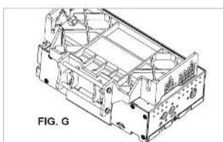
Note: If there is a depth issue with the radio module in the top position, move it to the bottom location by inverting the mounting bracket assembly. (FIG. G)
PROCEED TO STEP 5 on Page 16
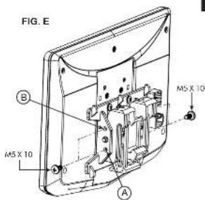
VERTICAL TILT: Use Hole A for no vertical tilt or Hole B for 8 degrees of vertical tilt. Insert a M5 X 10 on each side of the clamp assembly at desired tilt.
natural_image
Technical line drawing of a mechanical housing or enclosure with internal components (no text or symbols)4A
9
4B
Using a Double DIN Dash Kit:
Radio chassis mounts to the kit brackets in the sub-dash, not to the kit main frame
Display Adjustment & Mounting:
- Use all 8 kit mounting screws to attach the radio module & plastic mounting bracket assembly to the kit brackets at the front most location (not to exceed the front of the kit bracket). (FIG. H)
a. (4x) #10 X 3/8 screws for the bottom locations
b. (4x) M5 X 10 or (4x) M4 X 10 screws for the radio module locations (use any combination of screws to locate the radio in the best position)
Note: There are multiple mounting holes on the plastic mounting bracket to allow adjustment of the mounting depth. You may drill additional holes in the mounting bracket and/or the dash kit brackets to align the display in the best position and ensure you can use all 8 mounting screws. - Install the assembly (from Step 1) into the vehicle (using factory screws/bolts).
- Install the dash kit main frame and any factory panels that would affect the display installation.
Note: If there is a depth issue with the radio module in the top position, move it to the bottom location by inverting the mounting bracket assembly. (FIG. I)
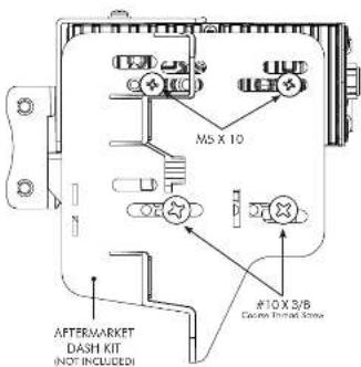
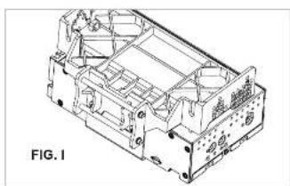
natural_image
Technical line drawing of an internal mechanical housing component (no text or symbols)10
- Attach the display to the mounting bracket assembly by hooking bottom spring hook and then pushing up and hooking top hooks. (FIG. J)
- Determine the desired position of the display: a. Display can be vertical or tilted up (FIG. K) b. Display can slide up or down (Page 7) c. Display can be tilted horizontally (Page 7 - FIG. B)
- Determine the final front to back position by measuring the shortest distance between the display to the dash kit main frame or the factory dash and subtract that distance/measurement by 0.25"
Note: Do not push the display all the way up against the dash. Leave enough bottom gap as the display's bottom edge rotates towards the dash. - Remove the display from the bracket assembly by pushing up from compression spring side (1) and swing out to unhook top (2). (FIG. L)
- Remove the radio module & mounting bracket assembly from the vehicle. Using the measurement taken in step 6, slide the radio module & bracket assembly back to that distance.
PROCEED TO STEP 5 on Page 16
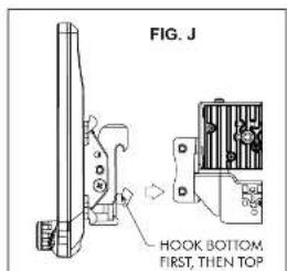
NOTE: BOOT AND DASH KIT NOT SHOWN
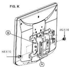
VERTICAL TILT: Use Hole A for no vertical tilt or Hole B for 8 degrees of vertical tilt. Insert a M5 X 10 on each side of the clamp assembly at desired tilt.
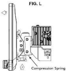

Using Factory Radio Brackets:
Radio chassis mounts to the factory brackets in the sub-dash
Display Adjustment & Mounting:
- Use all 8 kit mounting screws to attach the radio module & plastic mounting bracket assembly to the factory brackets. (FIG. M)
a. (4x) #10 X 3/8 screws for the bottom locations
b. (4x) M5 X 10 or (4x) M4 X 10 screws for the top locations (radio module).
If factory bracket is thinner than 1mm, add a washer to space the screws out.
New holes in the factory brackets may need to be drilled for optimal screen position
Note: There are multiple mounting holes on the plastic mounting bracket to allow adjusting the mounting depth. You may drill additional holes in the mounting bracket and/or the factory brackets to align the display in the best position and ensure you can use all 8 mounting screws.
-
Install the assembly (from Step 1) into the vehicle (using factory screws/bolts).
-
Install the dash kit main frame and any factory panels that would affect the display installation.
Note: If there is a depth issue with the radio module in the top position, move it to the bottom location by inverting the mounting bracket assembly. (FIG. N)
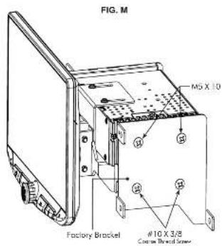
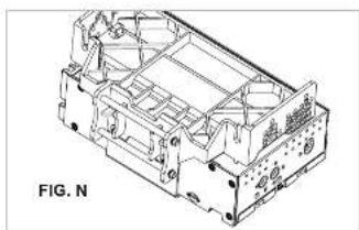
natural_image
Technical line drawing of an internal mechanical housing component (no text or symbols)-
Attach the display to the mounting bracket assembly by hooking bottom spring hook and then pushing up and hooking top hooks. (FIG. O)
-
Determine the desired position of the display: a. Display can be vertical or tilted up (FIG. P) b. Display can slide up or down (Page 7) c. Display can be tilted horizontally (Page 7 - FIG. B)
-
Determine the final front to back position by measuring the shortest distance between the display to the dash kit main frame or the factory dash and subtract that distance/measurement by 0.25^
Note: Do not push the display all the way up against the dash. Leave enough bottom gap as the display's bottom edge rotates towards the dash.
-
Remove the display from the bracket assembly by pushing up from compression spring side (1) and swing out to unhook top (2). (FIG. Q)
-
Remove the radio module & mounting bracket assembly from the vehicle. Using the measurement taken in step 6, install the radio module & bracket assembly back to that distance. (New holes in the factory brackets may need to be drilled).
PROCEED TO STEP 5 on Page 16
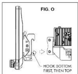
NOTE: BOOT AND DASH KIT NOT SHOWN
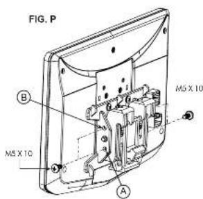
VERTICAL TILT: Use Hole A for no vertical tilt or Hole B for 8 degrees of vertical tilt. Insert a M5 X 10 on each side of the clamp assembly at desired tilt.
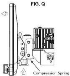
4D
Using a Single DIN ISO Mountable Dash Kit:
Radio chassis mounts separately into the sub-dash
Display Adjustment & Mounting:
- Install the dash kit brackets to the main frame.
- Making sure to use 4 screws, loosely attach the plastic mounting bracket assembly to the side kit brackets. (FIG. R) a. (4x) #10 X 3/8 screws
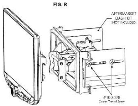
- Attach the display to the bracket assembly. (FIG. S)
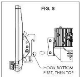
NOTE: BOOT AND DASH KIT NOT SHOWN
14
- Determine the desired position of the display: a. Display can be vertical or tilted up (FIG. T) b. Display can slide up or down (Page 7) C. Display can be tilted horizontally (Page 7 – FIG. B)
Note: There are multiple mounting holes on the mounting bracket to allow adjusting the mounting depth. You may drill additional holes in the mounting bracket and/or the dash kit brackets to align the display in the best position and ensure you can use 4 mounting screws.
- Once in the desired position, tighten screws to the mounting bracket assembly.
Note: If the display prevents the factory dash panel(s) from being installed last, do not push the display all the way up against the dash kit. Leave enough bottom gap as the display's bottom edge rotates towards the dash kit.
- Remove the display from the bracket assembly by pushing up from compression spring side (1) and swing out to unhook top (2). (FIG. U)
Note: The plastic mounting bracket assembly may be inverted to align the display in the best position. (FIG. V)
PROCEED TO STEP 5 on Page 16
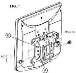
VERTICAL TILT: Use Hole A for no vertical tilt or Hole B for 8 degrees of vertical tilt. Insert a M5 X 10 on each side of the clamp assembly at desired tilt.
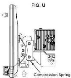
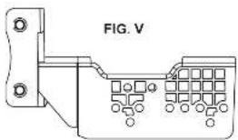
natural_image
Pure electrical connector diagram without any text or symbols15
Final Assembly
5
If needed, attach the rubber boot to the display clamp assembly by aligning the notch on the top edge as shown, and hook the boot to the clamp at 5 locations. (FIG. W)
Note: The boot is not required if display sits very close to the dash/dash kit and no large gap is seen.
6
After all wiring connections are made in the next section, the dash kit with the radio chassis and bracket assembly, should be installed and any factory panels reinstalled. Connect the 8 Pin Display Power Harness and the LVDS Video Cable to the back of the display and attach display to mounting bracket.
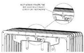
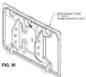
Wiring and Connections
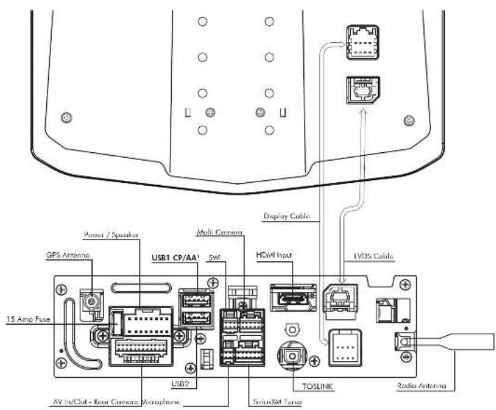
^1 The top USB1 must be used for Apple CarPlay and Android Auto.
^2 GPS Antenna must be installed for accurate operation of Apple CarPlay, Android Auto & internal Navigation.
Wiring and Connections
16 Pin Power / Speaker Harness
Connect radio power and speaker connections to a vehicle specific harness (sold separately) referencing diagram below.
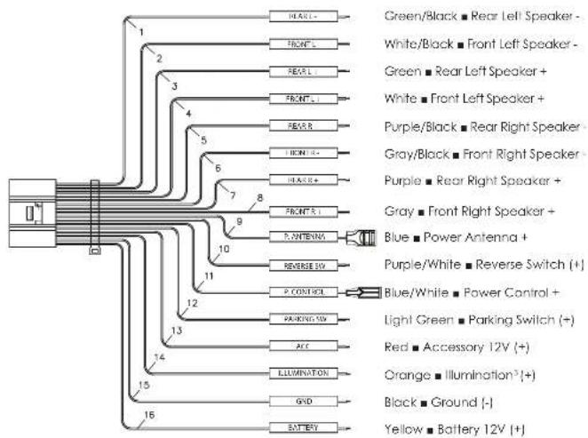
flowchart
graph TD
    A["LED"] --> B["1"]
    A --> C["2"]
    A --> D["3"]
    A --> E["4"]
    A --> F["5"]
    A --> G["6"]
    A --> H["7"]
    A --> I["8"]
    A --> J["9"]
    A --> K["10"]
    A --> L["11"]
    A --> M["12"]
    A --> N["13"]
    A --> O["14"]
    A --> P["15"]
    A --> Q["16"]

    B --> R["HEADL -"]
    B --> S["FRONTL -"]
    B --> T["REARL -"]
    B --> U["FRONTL +"]
    B --> V["REARR -"]
    B --> W["LIGHTL -"]
    B --> X["PEACHL +"]

    C --> Y["GREEN/Black ■ Rear Left Speaker -"]
    C --> Z["WHITE/Black ■ Front Left Speaker -"]
    C --> AA["GREEN ■ Rear Left Speaker +"]
    C --> AB["WHITE ■ Front Left Speaker +"]

    D --> AC["Purple/Black ■ Rear Right Speaker -"]
    D --> AD["GRAY/Black ■ Front Right Speaker -"]
    D --> AE["Purple ■ Rear Right Speaker +"]

    E --> AF["Purple/White ■ Reverse Switch (+)"]

    F --> AG["PAGE/RATE -"]
    F --> AH["PANTENIX -"]

    G --> AI["PUCR/SW -"]
    G --> AJ["PUCR/SW +"]

    H --> AK["PUCR/SW -"]
    H --> AL["PUCR/SW +"]

    I --> AM["PUCR/SW -"]
    I --> AN["PUCR/SW +"]

    J --> AO["PUCR/SW -"]
    J --> AP["PUCR/SW +"]

    K --> AQ["PUCR/SW -"]
    K --> AR["PUCR/SW +"]

    L --> AS["PUCR/SW -"]
    L --> AT["PUCR/SW +"]

    M --> AU["PUCR/SW -"]
    M --> AV["PUCR/SW +"]

    N --> AW["PUCR/SW -"]
    N --> AX["PUCR/SW +"]

    O --> AY["PUCR/SW -"]
    O --> AZ["PUCR/SW +"]

    P --> BA["PUCR/SW -"]
    P --> BB["PUCR/SW +"]

    Q --> BC["PUCR/SW -"]
    Q --> BD["PUCR/SW +"]

    R --> BE["Blue/White ■ Power Control +"]

    S --> BF["Light Green ■ Parking Switch (+)"]

    T --> BG["Red ■ Accessory 12V (+)"]

    U --> BH["Orange ■ Illumination*+"]

    V --> BI["Black ■ Ground (-)"]

    W --> BJ["Battery -"]

    X --> BK["Battery 12V (+)"]

    Y --> BL["Battery 12V (+)"]

    AC --> BM["Battery 12V (+)"]

    AD --> BN["Battery 12V (+)"]

    AE --> BO["Battery 12V (+)"]

    AF --> BP["Battery 12V (+)"]

    AG --> BQ["Battery 12V (+)"]

    AH --> BA["Battery 12V (+)"]

    AI --> BB["Battery 12V (+)"]

    AJ --> BC["Battery 12V (+)"]

    AK --> BD["Battery 12V (+)"]

    AL --> BE["Battery 12V (+)"]

    AM --> BF["Battery 12V (+)"]

    AN --> BG["Battery 12V (+)"]

    AO --> BH["Battery 12V (+)"]

    AU --> BI["Battery 12V (+)"]

    AV["Battery 12V (+)"]

    AW["Battery 12V (+)"]

    AX["Battery 12V (+)"]

    AZ["Battery 12V (+)"]

    BA["Battery 12V (+)"]

    BB["Battery 12V (+)"]

    BC["Battery 12V (+)"]

    AD["Battery 12V (+)"]

    AE["Battery 12V (+)"]

    AF["Battery 12V (+)"]

    AG["Battery 12V (+)"]

    AH["Battery 12V (+)"]

    AI["Battery 12V (+)"]

    AJ["Battery 12V (+)"]

    AK["Battery 12V (+)"]

    AL["Battery 12V (+)"]

    AMB["Battery 12V (+)"]

    ANB["Battery 12V (+)"]

    AOB["Battery 12V (+)"]

    AP["Battery 12V (+)"]

    AQ["Battery 12V (+)"]

    ARB["Battery 12V (+)"]

    ASB["Battery 12V (+)"]

    ATB["Battery 12V (+)"]

    AUIC["Battery 12V (+)"]

    AVIC["Battery 12V (+)"]

    AWIC["Battery 12V (+)"]

    AXIC["Battery 12V (+)"]

    AYIC["Battery 12V (+)"]

    AZI["Battery 12V (+)"]

    AYJB["Battery 12V (+)"]

    AXJX["Battery 12V (+)"]

    AXKX["Battery 12V (+)"]

    AXLYB["Battery 12V (+)"]

    AXYQB["Battery 12V (+)"]

    AXZYXB["Battery 12V (+)"]

    AXZYXQB["Battery 12V (-)"]

    AXZYXQXQB["Battery 12V (+)"]
2 Illumination wire must be connected for Day/Night and Auto Dimming to work.
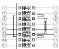
Connector View is pin side
Wiring and Connections
24 Pin AV / Rear Camera Harness
Audio/Video Inputs & Outputs / Rear Camera Video Input / Resistive Steering Wheel Control Inputs To program SWC, go to SETTINGS > Systems Settings > Installer Settings > Passcode:0052 > Advanced Vehicle Settings > Steering Wheel Control. Do not use if using a PAC SWI Interface.
| Analog Steering Wheel Control Input | A1 Brown / Black SWC Key 2 | |
| A2 Brown SWC Key 1 | ||
| A3 Black SWC Ground | ||
| Audio / Video input | A4 Yellow RCA Video Input | |
| A5 White RCA Audio Input Left | ||
| A6 Red RCA Audio Input Right | ||
| A7 Yellow RCA Camera Input | ||
| Video Output ^1 | A8 Yellow RCA Video Output 1 | |
| A9 Yellow RCA Video Output 2 | ||
| Audio Output | A10 White RCA Zone 2 Left | |
| A11 Red RCA Zone 2 Right | ||
| A12 Red RCA Right front | ||
| A13 White RCA Left Front | ||
| A14 Red RCA Right Rear | ||
| A15 White RCA Left Rear | ||
| A16 Brown RCA Left Subwoofer | ||
| A17 Blut RCA Right Subwoofer | ||
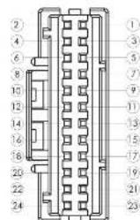
Connector View is pin side
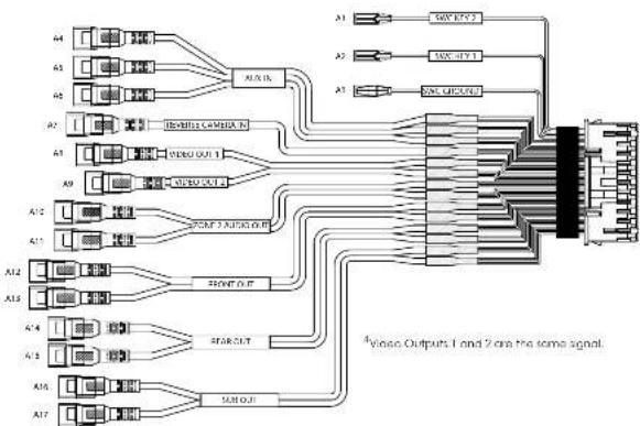
flowchart
graph TD
    A4 --> A1
    A5 --> A2
    A6 --> A3
    A7 --> A1
    A8 --> A2
    A9 --> A3
    A10 --> B1
    A11 --> B2
    A12 --> B3
    A13 --> B4
    A14 --> B5
    A15 --> B6
    A16 --> B7
    A17 --> B8
    B1 --> C["Switch"]
    B2 --> C
    B3 --> C
    B4 --> C
    B5 --> C
    B6 --> C
    B7 --> C
    B8 --> C
    style C fill:#f9f,stroke:#333,stroke-width:2px
    note right of C: "Video Outputs 1 and 2 are the same signal."
    note right of C: "Video Outputs 1 and 2 are the same signal."
SiriusXM® Harness
For connecting optional SiriusXM SXV 300 satellite radio tuner.
Wiring and Connections
6 Pin SWI / IR Harness
3.5mm Input for optional Steering Wheel Control Interface
(PAC Audio SWI-CP2 is recommended for full compatibility and advanced features. Visit PAC-Audio.com)

4 Pin Microphone / Camera Audio Harness
Input for External Microphone (included) used for hands-free calling, Apple CarPlay and Android Auto / Optional reverse camera audio input

10 Pin Multi Camera Harness
3 additional camera inputs and triggers / Vehicle Speed / PAC Link
Camera Triggers 2 & 3 will accept a pulsing + trigger (turn signal).
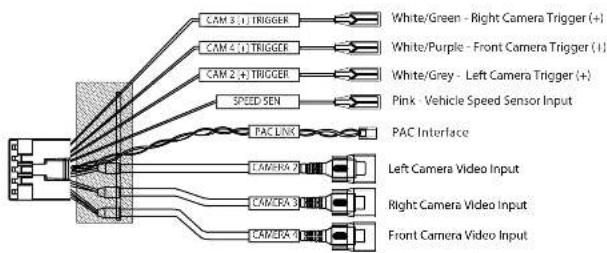
Dimensions (in)
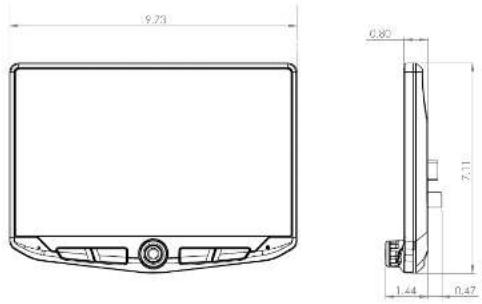
DIMENSIONS ARE IN INCHES
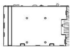
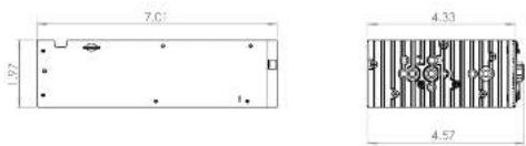
DIMENSIONS ARE IN INCHES
Upgrades/OptionsTroubleshooting
Black Screen with Audio
Touch the screen anywhere as it may have been turned off.
Ensure the display cables on the back of the display are fully locked into place and also properly connected at the back of the radio module.
Installer Settings
To access the installer Settings for firmware updates, SWC programming, factory reset, go to MENU > SETTINGS > SYSTEM SETTINGS > INSTALLER SETTINGS > Passcode: 0052 > OK
Bluetooth
Device will not pair
Ensure Bluetooth is tuned ON in your device settings. Delete all unused devices. Delete only 'Stringer' device. Restart/Reboot device and try pairing again.
Music Volume is low
- Turn up volume on device - Turn up volume on head unit - Turn up BT Volume Gain [MENU > SOUND SETTINGS > AUDIO
SETTINGS > ADVANCED SETTINGS > SOURCE GAIN
Phone Volume is low
- Turn up volume on device - Turn up volume on head unit - Turn up BT Volume Gain (MENU > SOUND SETTINGS > AUDIO SETTINGS > ADVANCED SETTINGS > SOURCE GAIN)
- turn Up Mic Gain (MENU > PHONE > SETTINGS)
No Microphone / Voice Control Sel Microphone location (MENU > PHONE > SETTINGS)
Apple CarPlay
Apple CarPlay will not start/launch Ensure an Apple certified cable is being used Ensure cable is plugged into USB #1 (tcp) - Make sure Apple CarPlay is turned ON (MENU) > SETTINGS > SYSTEM, SETTINGS > Apple CarPlay
Android Auto
Android Aula
Ensure a USB certified cable is being used. Make sure Android Auto app is downloaded and installed on your device. Ensure cable is plugged into USB #1 (top) - Make sure Android Auto is turned ON (MENU > SETTINGS > SYSTEM SETTINGS > Android Auto)
SiriusXM Satellite RadioGene
Check Antenna
The radio has detected a fault with the SiriusXM anlenna. The anlenna cable may be either disconnected or damaged.
- Very that the entire cable is connected to the SiriusXM Connect Vehicle Tuner. - Inspect the entire cable for damage and links.
Replace the citalenna if the case is damaged. SiusXM products are available of your local car audio retailer or online at www.shop.situsam.com.
Check Tuner
The radio is having difficulty communicating with the Situ xom Connect vehicle tuner, the tuner may be disconnected or damaged.
Verify that the Siusim Connect Vehicle tuner cable is securely connected to the radio.
No Signal
The SiriusXM Connect Vehicle Tuner is having difficulty receiving the SiriusXM toll signal. - Very that your vehicle's outdoors with a
clear view of the sky. - Vary that the Sinuskv magnetic mount onlenna's mounted on a metal surface on the outside of the vehicle.
- Move the SiriusXM antenna away from any ostructions. Inspect the antenna cable for damage and knots.
- Consult the SiriusXV Connect Vehicle Lower Installation manual for more information on antenna installation.
Balance the ontology if the code is damaged. ShisXM products are available of your local car audio retailer or online at www.shop.shisxm.com.
Channel Locked
The channel that has been requested is locked by the radio's Parental Control feature. See the Parental Control section, on Page 17 of the User Guide available on the Slinger website, for more information on the Parental Control feature and how to access locked channels.
Subscription Updated
The radio has deleted a change in your sinusXeI subscription status.
Press anywhere on the screen to clear the message.
In the U.S.A., visit www.shusam.com or call 1-866-633-2349 if you have questions about your subscription. In Canada, visit www.shusam.co or call 1-877-438-7677 if you have questions about your subscription.
Channel Unavailable
The channel that you have requested is not a valid SiriusXM channel or the channel met you were listening to is no longer available. The message may also appear briefly when first connecting a new SiriusXM Connect Vehicle tuner.
Visit www.sn.sxm.com for more information about the SiusXM channel lineup. title, risks.
SiriusXM Satellite Radio (cont)
Memory End
This message will display when the beginning of stored audio has been reached. You cannot rewind any further. Memory full
The stored audio memory has become full while audio was paused. Resume okayback.
Channel Unsubscribed
The channel that has been requested is not included in your SiriusXM subscription package or the channel that you were listening to be no longer included in your SiriusXM subscription package.
in the U.S.A. visit www.sriuxm.com or call 1-866-635-2349 if you have questions about your subscription package or would like to subscribe to this channel, in Canada, visit www.sriuxm.ca or call 1-877-438-9677.
Video/Cameras
Rear Camera not displaying in reverse - Make sure rear camera trigger is CN - (MENU > CAMERAS > CAMERA SETTINGS) - If display is showing NO SIGNAL in reverse, ensure camera RCA is plugged into correct RCA input [CAMERA IN]. - Confirm camera has power and ground. - Confirm camera trigger is receiving positive 12V. Note: NISC and PAL video formats only.
Navigation Ready
Add optional iGO Navigation with part number SE-P14. Insert the purchased Micro SD card into the front of the radio module. HEIGHT0 and iGO are optimized for ease of use and driving safety.
Navigation SD Cord
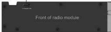
Best Kits
Dash kits, wire harnesses and antenna adapters. PAC-Audio.com
PAC Audio
Retain the factory vehicle features with RadioPRO Radio Replacement Modules, Steering Wheel Interfaces, Factory Camera and USB retention. PAC-Audio.com
EchoMaster
Add a Rear Camera, or Side and Front Cameras. EchoMaster.com
Phoenix Gold
Take advantage of the 6 channel / 4v outputs or variable TOSLINK by adding an amp, processor or speakers. PhoenixGold.com.com




NOTES:
Stinger®
Multi Media Infotainment System Warranty Registration
Thank you for choosing a Stinger Electronics product. Completing this form will register your purchase with Stinger and will make it possible to send you updated information on your product and special offers.
*Please include a copy of your original sales receipt to qualify for your warranty.
Name:
Street:
City: ____ State: ____ Zip: ____
Email:
Date of Purchase: ____ Place of Purchase: ____
Model#: ____ Serial#: ____
Stinger Product Warranty
LIMITED WARRANTY ON Multi Media Infotainment Systems
Stinger warrants this product to be free of defects in materials and workmanship for a period of one (1) year from the original date of purchase. This warranty is not transferable and applies only to the original purchaser from an authorized Stinger dealer in the United States of America only. Should service be necessary under this warranty for any reason due to manufacturing defect or malfunction, Stinger will (at its discretion) repair or replace the defective product with new or re-manufactured product at no charge. Damage caused by the following is not covered under warranty: accident, misuse, abuse, product modification or neglect, failure to follow installation instructions, unauthorized repair attempts, misrepresentations by the seller. This warranty does not cover incidental or consequential damages and does not cover the cost of removing or reinstalling the unit(s). Cosmetic damage due to accident or normal wear and tear is not covered under warranty.
INTERNATIONAL WARRANTIES:
Products purchased outside the United States of America are covered only by that country's Authorized Stinger reseller and not by Stinger. Consumers needing service or warranty information for these products must contact that country's reseller for information.
Warranty Registration Card

(FOLD HERE)
Place Stamp Here
Stinger Electronics
C/O AAMP Global Customer Service
15500 Lightwave DR Suite 202
Clearwater, FL 33760
WELCOME TO YOUR NEW

HEIGH10·
Enjoy the ride
User Guide Download
Download the User Guide for your
HEIGH10 Modular Multimedia Display System
https://stingerelectronics.com/products/heigh10
Check Out StingerElectronics.com for
INSTALL GUIDES | UPDATES | TECH TIPS
VIDEOS | ACCESSORIES
DC-UN1810 / REV 041420
- Introduction and Features
- Important Notes
- We recommend reading this manual thoroughly to familiarize yourself with the entire process prior to beginning the installation.
- Recommended Tools
- Included Components
- Wiring Overview
- Factory Radio Code
- Section 1: Disassembly
- Part One: Center Dash Disassembly
- Section 1: Disassembly (cont.)
- Part Two: Lower Storage Compartment Removal
- Part Three: Glove Box Removal (Optional)
- Part Four: A Pillar Removal
- Part Five: Lower Steering Column Cover Removal (Optional)
- Section 2: In-Vehicle Harness Connections and Preparation
- Part One: Dual USB Extension (SSUSB2)
- Section 2: In-Vehicle Harness Connections and Preparation (cont.)
- Part Two: Factory Rear Camera Retention Harness (CAM-GM51-HAR)
- Part Three: Steering Wheel Control (SWC) Retention Harness (GM5LIN-SW-HAR)
- Part Four: GPS Antenna
- Part Five: Vehicle Side Plug Relocation and Antenna Adapter
- Section 3: Interface and Main Harness Connections and Preparation
- Part One: RP5-GM51 Radio Interface Connections
- Part Two: Main Harness Connections (SR-GM14H-HAR-A)
- Section Four: Display Mounting Panel Preparation
- Section Five: Radio Module Preparation
- Part One: Radio Module Side Brackets
- Step 2 Step 1 Step 3
- Step 4 Step 5
- Section 5: Radio Unit Installation
- Part One: In-Vehicle Harness and Cabling Connections
- Section 5: Radio Unit Installation (cont.)
- Part Two: Radio Unit Mounting (cont.)
- Step 5 Step 4
- Product Updates (Firmware)
- Firmware Updates (RadioPRO)
- Firmware Updates (Stinger Radio and PAC Application APK)
- Reset / Restoring Interface Factory Settings
- Technical Support
- Stinger®
- HEIGH10·
- USER GUIDE
- WELCOME TO YOUR NEW
- Bluetooth®
- HDMI®
- Visit StingerElectronics.com for updates and further detailed information.
- TECHNICAL SUPPORT:
- CUSTOMER SOLUTIONS:
- CONTENTS
- THE BASICS
- POWER UP!
- SELECTING A SOURCE
- QUICK TIP
- SETTING THE TIME
- Press the HOME BUTTON > Radio to select the Radio
- Press the HOME BUTTON > Phone to select the Phone
- Bluetooth PHONE Bluetooth PHONE
- Pairing a Device
- NOTE!
- BT Device Settings
- Devices ▶
- Auto Connect [ON/OFF]
- Pin Code [CHANGE]
- Microphone [Internal/External]
- Microphone Gain [0-6]
- Bluetooth PHONE
- Bluetooth MUSIC
- Contacts
- Call Log
- ®Satelite Radio (OPTIONAL)
- Activating your SiriusXM Subscription
- SiriusXM Satellite RadioSiri
- SiriusXM Satellite Radio SiriusXM
- Satelite Radio
- Channels [CH]
- Categories [CAT]
- Direct Tuning
- SiriusXM Replay™
- Replay Controls
- SiriusXM Satellite Radio
- USB Media
- Parental Control
- Lock Mature Channels:
- Unlock Mature Channels:
- Set/Change Lock Code:
- Reset Lock Code:
- Apple CarPlay®
- Set up Apple CarPlay
- WARNING!
- CAMERAS
- Mute On Reverse
- Settings > Camera Settings
- SETTINGS
- Press the HOME BUTTON > Settings
- Settings > System Settings > Apple CarPlay
- Settings > Clock
- Settings > System Settings > Android Auto
- Settings > System Settings
- Settings > Illumination
- Stinger
- SETTINGSSE1
- Settings > Background
- Settings > Display Settings
- Settings > Tabs
- SOUND SETTINGS
- Settings > Sound Settings
- Sound Settings > Equalizer
- Saving EQ Settings
- Sound Settings > Factory EQ
- SOUND SETTINGS SOUND SETTINGS
- Sound Settings > Crossover
- Saving Crossover Settings
- Sound Settings > Time Correction
- Saving Time Correction Settings
- Settings > Sound Settings > Advanced Settings
- Defeat [ON-OFF]
- Source Gain Settings ▶
- Volume Settings ▶
- Start Volume [LAST-CUSTOM]
- Volume Slider [0-40]
- Reset Button
- TROUBLE SHOOTING
- Black Screen with Audio
- Display Image Is Inverted
- Bluetooth
- Device will not Pair
- Music Volume is low
- Phone Volume is low
- Video/Cameras
- SiriusXM Satellite RadioGene
- Check Antenna
- Check Tuner
- No Signal
- Channel Locked
- Subscription Updated
- Channel Unavailable
- Memory End
- Memory Full
- Channel Unsubscribed
- Apple CarPlaySiriusXM Satellite
- Apple CarPlay will not start/launch
- Android Auto
- SPECIFICATIONS SPECIFICATIONS
- GENERAL
- DIMENSIONS
- DISPLAY
- AUDIO
- AUDIO (CONT)
- USB
- FM TUNER
- AM TUNER
- CAMERA(S) VIDEO INPUTS
- HDMI INPUT
- TOSLINK (OPTICAL)
- BACKGROUND IMAGE (USER)
- AUDIO/VIDEO FORMATS
- VIDEO
- IMAGE
- ELEV8·
- FEATURES
- INSTALLATION GUIDE
- PRECAUTIONS
- Visit StingerElectronics.com for User Guide | Install Guides | Updates | Tech Tips
- Pre-Assembly
- Display Assembly
- Multiple Mounting Options
- 4A
- Using a Double DIN Dash Kit:
- Radio chassis mounts to the brackets attached to the kit main frame
- Display Adjustment & Mounting:
- Using Factory Radio Brackets:
- Radio chassis mounts to the factory brackets in the sub-dash
- New holes in the factory brackets may need to be drilled for optimal screen position
- Using a Single DIN ISO Mountable Dash Kit:
- Final Assembly
- 5
- 6
- Wiring and Connections
- Pin Power / Speaker Harness
- Pin AV / Rear Camera Harness
- SiriusXM® Harness
- Pin SWI / IR Harness
- Pin Microphone / Camera Audio Harness
- Pin Multi Camera Harness
- Dimensions (in)
- Upgrades/OptionsTroubleshooting
- Installer Settings
- Apple CarPlay
- SiriusXM Satellite Radio (cont)
- Navigation Ready
- NOTES:
- Multi Media Infotainment System Warranty Registration
- Stinger Product Warranty
- LIMITED WARRANTY ON Multi Media Infotainment Systems
- INTERNATIONAL WARRANTIES:
- User Guide Download
Brand : Stinger
Model : SR-GM14H
Category : Car radio