SPK-C612 - Loudspeaker Kramer - Free user manual and instructions
Find the device manual for free SPK-C612 Kramer in PDF.


| Product Type | Passive 2-way loudspeaker |
| Brand | Kramer |
| Model | SPK-C612 |
| Woofer Size | 6.5 inches (165 mm) |
| Tweeter Size | 1 inch (25 mm) soft dome |
| Impedance | 8 ohms |
| Power Handling (RMS) | 100 W |
| Power Handling (Peak) | 200 W |
| Frequency Response | 65 Hz - 20 kHz |
| Sensitivity | 90 dB SPL (1W/1m) |
| Dimensions (H x W x D) | 12.6 x 7.9 x 9.1 inches (320 x 200 x 230 mm) |
| Weight | 15.4 lbs (7.0 kg) |
| Enclosure Material | MDF with vinyl finish |
| Input Connectors | Binding posts |
| Mounting Options | Optional wall mount bracket |
| Recommended Amplifier Power | 20 - 200 W per channel |
| Cleaning Instructions | Wipe with dry cloth; do not use solvents or water |
| Safety Precautions | Do not exceed rated power; keep away from moisture |
| Spare Parts & Repairability | Contact Kramer support for replacement drivers or service |
| General Information | Designed for professional AV installations; suitable for nearfield monitoring |
Frequently Asked Questions - SPK-C612 Kramer
User questions about SPK-C612 Kramer
0 question about this device. Answer the ones you know or ask your own.
Ask a new question about this device
Download the instructions for your Loudspeaker in PDF format for free! Find your manual SPK-C612 - Kramer and take your electronic device back in hand. On this page are published all the documents necessary for the use of your device. SPK-C612 by Kramer.
USER MANUAL SPK-C612 Kramer
Closed-back Ceiling Speakers
Contents
1 Introduction 1
2 Getting Started 2
2.1 Achieving the Best Performance 2
3 Overview 3
4 Your SPK-C612 Closed-back Ceiling Speakers 4
5 Installing the SPK-C612 Closed-back Ceiling Speakers 6
5.1 Choosing the Best Location 6
5.2 Cutting the Ceiling Tile 6
5.3 Mounting the Speakers 7
5.4 Painting the Speaker 10
6 Technical Specifications 11
Figures
Figure 1: SPK-C612 in a Boardroom Setup 3
Figure 2: SPK-C612 Closed-back Ceiling Speaker 4
Figure 3: SPK-C612 Schematic Diagram 5
Figure 4: Mounting the SPK-C612 7
Figure 5: Plugging and Securing the Cable 8
Figure 6: Tighten the Mounting Tabs 9
Figure 7: Adjust Tap Selector 9
1 Introduction
Welcome to Kramer Electronics! Since 1981, Kramer Electronics has been providing a world of unique, creative, and affordable solutions to the vast range of problems that confront video, audio, presentation, and broadcasting professionals on a daily basis. In recent years, we have redesigned and upgraded most of our line, making the best even better!
Our 1,000-plus different models now appear in 11 groups that are clearly defined by function: GROUP 1: Distribution Amplifiers; GROUP 2: Switchers and Routers; GROUP 3: Control Systems; GROUP 4: Format/Standards Converters; GROUP 5: Range Extenders and Repeaters; GROUP 6: Specialty AV Products; GROUP 7: Scan Converters and Scalers; GROUP 8: Cables and Connectors; GROUP 9: Room Connectivity; GROUP 10: Accessories and Rack Adapters and GROUP 11: Sierra Products.
Congratulations on purchasing your Kramer SPK-C612 Closed-back Ceiling Speakers, which are ideal for the following typical applications:
- Boardrooms
• Presentation venues
• Conference Rooms
- Training Rooms
• Educational classrooms
Hotel lobbies
The package includes the following items:
• A pair of SPK-C612 speakers
- Mounting kit
• This user manual

SPK-C612 is designed for indoor dry locations and are suitable for use in air handling spaces (plenum spaces).
2 Getting Started
We recommend that you:
- Unpack the equipment carefully and save the original box and packaging materials for possible future shipment
• Review the contents of this user manual
• Use Kramer high-performance high-resolution cables

Go to http://www.kramerelectronics.com to check for up-to-date user manuals, application programs, and to check if firmware upgrades are available (where appropriate).
2.1 Achieving the Best Performance
To achieve the best performance:
- Use only good quality connection cables (such as the Kramer BC-2S) to avoid interference, deterioration in signal quality due to poor matching, and elevated noise levels (often associated with low quality cables)
- Do not secure the cables in tight bundles or roll the slack into tight coils
- Avoid interference from neighboring electrical appliances that may adversely influence signal quality
- Position your Kramer SPK-C612 away from moisture, excessive sunlight and dust

To ensure that you obtain the best sound results, do not open the housing of the passive speaker or the active speaker.

UL2043 – Fire Test for Heat and Visible Smoke Release for Discrete Products and their Accessories Installed in Air-Handling Spaces.
3 Overview
The SPK-C612 consists of a pair of high performance closed back speakers. The pair can be mounted on the ceiling, as well as via a ceiling mounting kit used to safely secure the speakers to the ceiling.
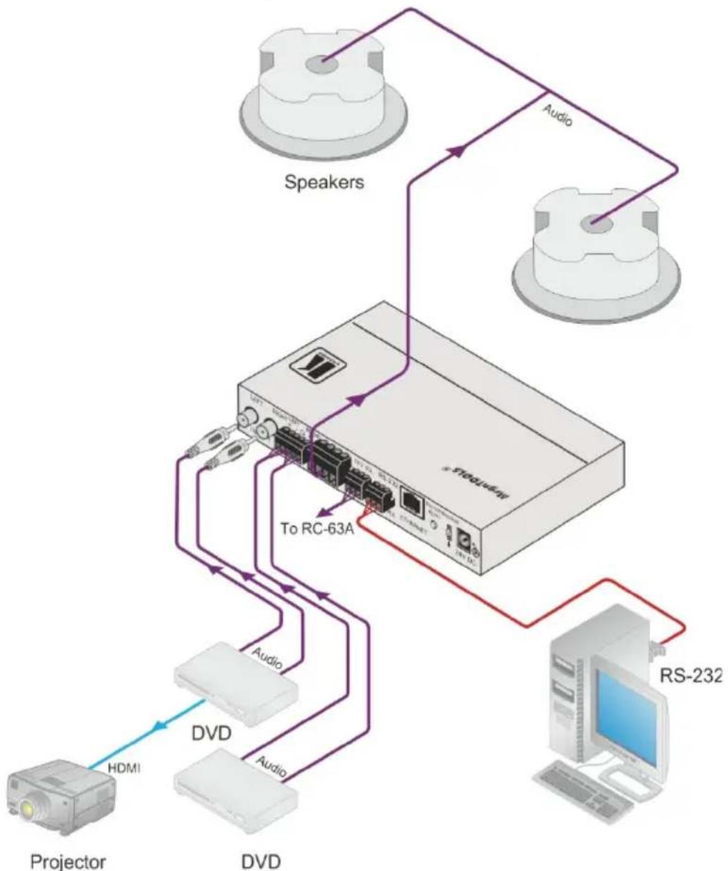
The SPK-C612 speakers feature a diameter of 6.5", a resistance of 8Ω and a closed-back depth of 7". Figure 1 shows an example of how the SPK-C612 can be installed in a boardroom setup:
flowchart
graph TD
    A["Projector"] -->|HDMI| B["ProLine/Net"]
    C["DVD"] -->|Audio| B
    D["RS-232"] -->|Audio| B
    B --> E["To RC-63A"]
    F[" Speakers"] --> B
    G["Audio"] --> B
    H["ProLine/Net"] -->|Audio| B
    style A fill:#f9f,stroke:#333
    style C fill:#f9f,stroke:#333
    style D fill:#f9f,stroke:#333
    style E fill:#ccf,stroke:#333
    style F fill:#ccf,stroke:#333
    style G fill:#ccf,stroke:#333
    style H fill:#ccf,stroke:#333
Figure 1: SPK-C612 in a Boardroom Setup
4 Your SPK-C612 Closed-back Ceiling Speakers
Figure 2 defines the SPK-C612:
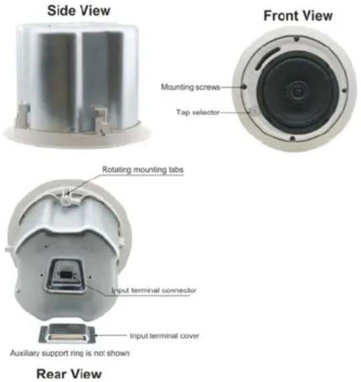
Figure 2: SPK-C612 Closed-back Ceiling Speaker
The following table defines the SPK-C612 hardware items (per speaker pair) for each model in the series:
| Description | |||||
| A pair of ceiling speakers (one shown) |  | Two grilles (one shown) |  | Cutout template | 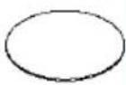 |
This table defines the ceiling mounting kit items:
| Four support rings screws |  | Two ceiling support rings (C-ring) – one shown |  | Two pairs of tile rails – one of a pair shown | 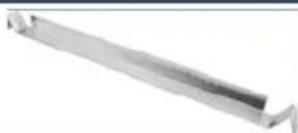 |
Each Closed-back Ceiling speaker is supported by a C-ring and two tile rails. The tile rails prevent the speakers from falling if the tile itself comes out or falls apart, as their ends catch onto the T-grid. When mounting onto the ceiling tiles, use both supports. When mounting onto a sheetrock ceiling, the C-ring alone is used to reinforce the ceiling material.

Be sure that the tiles can support the speaker. Smaller sized tiles or fiberglass-type tiles cannot support the weight of the speakers. When this is the case, the speakers will need additional support.
Figure 3 shows a schematic diagram of the SPK-C612:
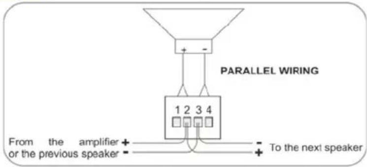
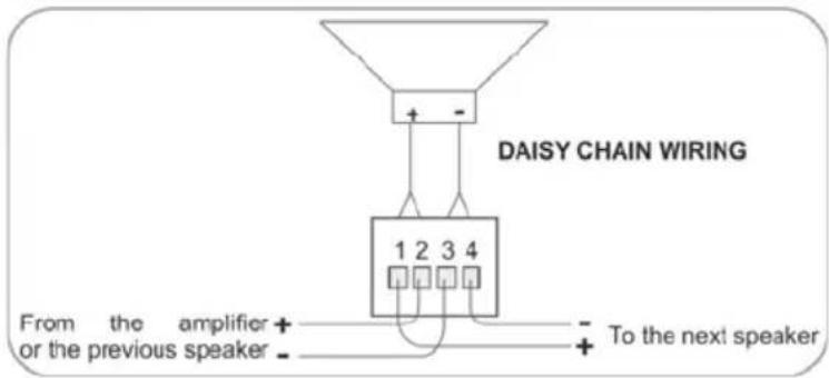
Figure 3: SPK-C612 Schematic Diagram
5 Installing the SPK-C612 Closed-back Ceiling Speakers
This section explains how to install the SPK-C612, that is:
- Choosing the best place to locate your speakers (see Section 5.1)
• Cutting the ceiling tile (see Section 5.2) - Mounting the Speakers (see Section 5.3)
• Painting the speakers (see Section 5.4)
5.1 Choosing the Best Location
Ideally, locate the speakers above the main listening area. Before doing so, be sure that:
- The desired location is free of obstructions, such as electrical piping, AC ducts or water lines, and so on
• There is enough space behind the mounting surface for the speakers - The rear side of the speaker is not blocked by wall studs or other objects
5.2 Cutting the Ceiling Tile
To cut the ceiling tile, do the following:
- Remove the circle in the supplied template.
Keep this template for later use as a mask, as you may want to paint the speakers (see Section 5.4) - Mark the opening in the correct location by tracing the hole in the template.
- Cut out the hole according to the template or with a circular cutter set to the appropriate cutout size.
Initially, you can cut a smaller area inside the marked hole just to be sure that the space above the speakers is clear - Route the wiring from the amplifier to the speakers' cutout holes, taking care not to place them next to electrical wires or at least at a distance of about two feet from an AC line.

Do not nail or staple the speaker wires.
If you are mounting the speakers onto a ceiling tile, remove the ceiling tiles where you plan to install the speakers. Use the template to trace and then cutout the speaker hole over an empty box.
The closed-back ceiling speakers are supported by the ceiling mounting kit (two C-rings and two pairs of tile rails; the tile rails prevent the speakers from falling if the tile itself comes out or falls apart, as their ends catch onto the T-grid). When mounting onto the ceiling tiles, use both supports.

Be sure that the tiles can support the speaker. Smaller sized tiles or fiberglass-type tiles cannot support the weight of the speakers. When this is the case, the speakers will need additional support.
When mounting onto a sheetrock ceiling, the C-ring alone is used to reinforce the ceiling material.
5.3 Mounting the Speakers
To mount the SPK-C612, do the following:
- Place the C-ring over the hole cut in the ceiling tile (on the "ceiling" side). Place it around the hole so that the tabs are located in parallel to the tile edges.
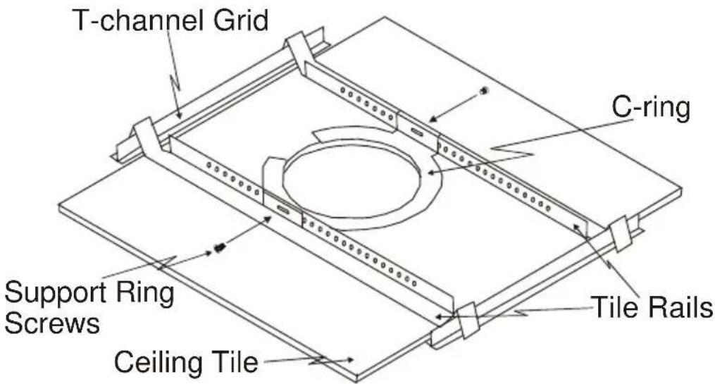
Figure 4: Mounting the SPK-C612
- Place the tile rails on the tile and snap them into the two tabs on the C-ring. Align the rails so that the ends extend over the T-channel grid.
- Insert a screw through each tab on the C-ring to secure the rails.
- Connect the speaker wires to the appropriate connector terminals:
■ PIN 1 and PIN 2 are connected internally and are positive (+)
■ PIN 3 and PIN 4 are connected internally and are negative (-)
Screw the hold-down screws on the connector until tight, using a small screwdriver.
You can connect the speakers in the two following possible layouts:
- Wiring in parallel: connect the wire pair of the subsequent speaker to PIN 2 and PIN 3. When one input connector is removed, subsequent speakers will remain connected (see Figure 3)
-
Daisy-chaining: connect the wire pair of the subsequent speaker to PIN 1 and PIN 4. When one input connector is removed, subsequent speakers will be disconnected (see Figure 3)
-
Plug the connector into the socket in the terminal cup of the speaker (see Figure 5).
-
Run the wires through the wires' opening in the input terminal cover plug and then into the terminal block connector of the speaker.
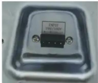
Figure 5: Plugging and Securing the Cable
-
Push the speaker into the ceiling hole until the front baffle rim is leveled with the ceiling.
-
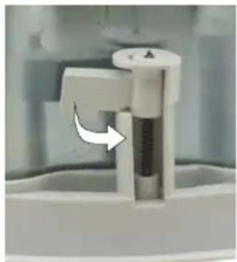
Tighten the mounting tabs by turning the screw counter clockwise (see Figure 6).
The first quarter turn, rotates the tab outwards, and the following turns tighten the tabs to the rear side of the ceiling surface
When tightening the mounting tabs, the tabs automatically turn outward, thus clamping the speaker to the wall from its rear side.
Note: Do not over-tighten the screws. It may cause damage to both the speakers and the surface.
natural_image
Close-up of a white plastic mechanical component with a curved arrow indicating rotation (no text or symbols visible)Figure 6: Tighten the Mounting Tabs
-
If required, you can further secure the speaker by connecting the speaker support ring to an independent secure anchor point.
-
Adjust each speaker to the appropriate tap setting before installing the grille (see Figure 7).
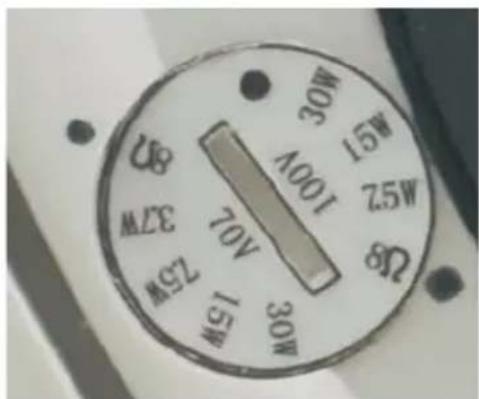
Figure 7: Adjust Tap Selector
11. Install the grilles to the speakers:
■ Push the grille fastener into the hole in front of the baffle
- Press the grille into place until the front of the grille is flush with the rim of the baffle
- Check that the grille is securely seated

To remove the grille, insert two bent paper clips into the holes in the grille and carefully pull it down. Repeat this around the perimeter of the grille until it is completely removed.
5.4 Painting the Speaker
You can paint the speakers before or after they are installed.
When painting before installation:
- Clean the rim and grille with mineral spirits or other light solvent that is unlikely to damage the surface
- Spray with color by holding the spray can at an angle of 45^

When spraying the grille, take care not to clog the holes in the grille as this will greatly reduce the sound quality of the speakers.
When painting after installation:
• Use the circle that you cut out of the template as a paint mask
• After you finish painting, remove the paint mask
6 Technical Specifications
| Audio and Power | |
| DESCRIPTION: | 2-way co-axial low-profile ceiling speakers with metal back can |
| HIGH FREQUENCY DRIVER: | 1" MYLAR dome tweeter |
| LOW FREQUENCY DRIVER: | 6.5" Polypropylene cone with rubber edge woofer |
| IMPEDANCE: 8Ω | |
| DISPERSION COVERAGE: 80° | |
| CROSSOVER FREQUENCY: 3kHz | |
| NOMINAL SENSITIVITY: 87dB SPL @1m, 1W | |
| DIRECTIVITY FACTOR (Q): | 5.1 (averaged 100Hz – 10kHz); 6.2 (2kHz) |
| DIRECTIVITY INDEX (DI): | 6.8dB (averaged 100Hz – 10kHz); 5.0dB (2kHz) |
| FREQUENCY RESPONSE: | 55Hz to 20kHz |
| INPUT POWER: | 30W RMS, 60W Max., continuous load (24hr) 40W |
| TRANSFORMER: | 70V – 3.7W/7.5W/15W/30W100V – 7.5W/15W/30W |
| RECOMMENDED AMPLIFIER POWER: | 30W |
| INPUT CONNECTOR: Terminal block | |
| Shipping and Installation | |
| WEIGHT PER SINGLE SPEAKER: | 2.85kg (6.28lbs) approx. |
| SHIPPING WEIGHT (FOR PAIR): | 8kg (17.64lbs) approx. |
| DIMENSIONS (OD): | 25.1cm (9.88") |
| CUT OUT SIZE (MOUNT DIMENSION): | 22.3cm (8.78") |
| MOUNT DEPTH: | 19.45cm (7.66") |
| ACCESSORIES: | Ceiling mounting kit |
| Specifications are within a 10% tolerance and are subject to change without notice at http://www.kramerelectronics.com | |
LIMITED WARRANTY
The warranty obligations of Kramer Electronics for this product are limited to the terms set forth below:
What is Covered
This limited warranty covers defects in materials and workmanship in this product.
What is Not Covered
This limited warranty does not cover any damage, deterioration or malfunction resulting from any alteration, modification, improper or unreasonable use or maintenance, misuse, abuse, accident, neglect, exposure to excess moisture, fire, improper packing and shipping (such claims must be presented to the carrier), lightning, power surges, or other acts of nature. This limited warranty does not cover any damage, deterioration or malfunction resulting from the installation or removal of this product from any installation, any unauthorized tampering with this product, any repairs attempted by anyone unauthorized by Kramer Electronics to make such repairs, or any other cause which does not relate directly to a defect in materials and/or workmanship of this product. This limited warranty does not cover cartons, equipment enclosures, cables or accessories used in conjunction with this product.
Without limiting any other exclusion herein, Kramer Electronics does not warrant that the product covered hereby, including, without limitation, the technology and/or integrated circuit(s) included in the product, will not become obsolete or that such items are or will remain compatible with any other product or technology with which the product may be used.
How Long Does this Coverage Last
One year as of this printing; please check our Web site for the most current and accurate warranty information.
Who is Covered
Only the original purchaser of this product is covered under this limited warranty. This limited warranty is not transferable to subsequent purchasers or owners of this product.
What Kramer Electronics will do
Kramer Electronics will, at its sole option, provide one of the following three remedies to whatever extent it shall deem necessary to satisfy a proper claim under this limited warranty:
- Elect to repair or facilitate the repair of any defective parts within a reasonable period of time, free of any charge for the necessary parts and labor to complete the repair and restore this product to its proper operating condition. Kramer Electronics will also pay the shipping costs necessary to return this product once the repair is complete.
- Replace this product with a direct replacement or with a similar product deemed by Kramer Electronics to perform substantially the same function as the original product.
- Issue a refund of the original purchase price less depreciation to be determined based on the age of the product at the time remedy is sought under this limited warranty.
What Kramer Electronics will not do Under This Limited Warranty
If this product is returned to Kramer Electronics or the authorized dealer from which it was purchased or any other party authorized to repair Kramer Electronics products, this product must be insured during shipment, with the insurance and shipping charges prepaid by you. If this product is returned uninsured, you assume all risks of loss or damage during shipment. Kramer Electronics will not be responsible for any costs related to the removal or re-installation of this product from or into any installation. Kramer Electronics will not be responsible for any costs related to any setting up this product, any adjustment of user controls or any programming required for a specific installation of this product.
How to Obtain a Remedy under this Limited Warranty
To obtain a remedy under this limited warranty, you must contact either the authorized Kramer Electronics reseller from whom you purchased this product or the Kramer Electronics office nearest you. For a list of authorized Kramer Electronics resellers and/or Kramer Electronics authorized service providers, please visit our web site at www.kramerelectronics.com or contact the Kramer Electronics office nearest you.
In order to pursue any remedy under this limited warranty, you must possess an original, dated receipt as proof of purchase from an authorized Kramer Electronics reseller. If this product is returned under this limited warranty, a return authorization number, obtained from Kramer Electronics, will be required. You may also be directed to an authorized reseller or a person authorized by Kramer Electronics to repair the product.
If it is decided that this product should be returned directly to Kramer Electronics, this product should be properly packed, preferably in the original carton, for shipping. Cartons not bearing a return authorization number will be refused.
Limitation on Liability
THE MAXIMUM LIABILITY OF KRAMER ELECTRONICS UNDER THIS LIMITED WARRANTY SHALL NOT EXCEED THE ACTUAL PURCHASE PRICE PAID FOR THE PRODUCT. TO THE MAXIMUM EXTENT PERMITTED BY LAW, KRAMER ELECTRONICS IS NOT RESPONSIBLE FOR DIRECT, SPECIAL, INCIDENTAL OR CONSEQUENTIAL DAMAGES RESULTING FROM ANY BREACH OF WARRANTY OR CONDITION, OR UNDER ANY OTHER LEGAL THEORY. Some countries, districts or states do not allow the exclusion or limitation of relief, special, incidental, consequential or indirect damages, or the limitation of liability to specified amounts, so the above limitations or exclusions may not apply to you.
ExclusiveRemedy
TO THE MAXIMUM EXTENT PERMITTED BY LAW, THIS LIMITED WARRANTY AND THE REMEDIES SET FORTH ABOVE ARE EXCLUSIVE AND IN LIEU OF ALL OTHER WARRANTIES, REMEDIES AND CONDITIONS, WHETHER ORAL OR WRITTEN, EXPRESS OR IMPLIED. TO THE MAXIMUM EXTENT PERMITTED BY LAW, KRAMER ELECTRONICS SPECIFICALLY DISCLAIMS ANY AND ALL IMPLIED WARRANTIES, INCLUDING, WITHOUT LIMITATION, WARRANTIES OF MERCHANTABILITY AND FITNESS FOR A PARTICULAR PURPOSE. IF KRAMER ELECTRONICS CANNOT LAWFULLY DISCLAIM OR EXCLUDE IMPLIED WARRANTIES UNDER APPLICABLE LAW, THEN ALL IMPLIED WARRANTIES COVERING THIS PRODUCT, INCLUDING WARRANTIES OF MERCHANTABILITY AND FITNESS FOR A PARTICULAR PURPOSE, SHALL APPLY TO THIS PRODUCT AS PROVIDED UNDER APPLICABLE LAW. IF ANY PRODUCT TO WHICH THIS LIMITED WARRANTY APPLIES IS A "CONSUMER PRODUCT" UNDER THE MAGNUSON-MOSS WARRANTY ACT (15 U.S.C.A. §2301, ET SEQ.) OR OTHER APPLICABLE LAW, THE FOREGOING DISCLAIMER OF IMPLIED WARRANTIES SHALL NOT APPLY TO YOU, AND ALL IMPLIED WARRANTIES ON THIS PRODUCT, INCLUDING WARRANTIES OF MERCHANTABILITY AND FITNESS FOR THE PARTICULAR PURPOSE, SHALL APPLY AS PROVIDED UNDER APPLICABLE LAW.
Other Conditions
This limited warranty gives you specific legal rights, and you may have other rights which vary from country to country or state to state.
This limited warranty is void if (i) the label bearing the serial number of this product has been removed or defaced, (ii) the product is not distributed by Kramer Electronics or (iii) this product is not purchased from an authorized Kramer Electronics reseller. If you are unsure whether a reseller is an authorized Kramer Electronics reseller, please visit our Web site at www.kramarelectronics.com or contact a Kramer Electronics office from the list at the end of this document.
Your rights under this limited warranty are not diminished if you do not complete and return the product registration form or complete and submit the online product registration form. Kramer Electronics thanks you for purchasing a Kramer Electronics product. We hope it will give you years of satisfaction.

For @the @latest information on our products and a @list @of @Kramer @distributors, visit our W@eb site where updates to this user manual may be found.
W@e welcome y our questions, comments, and feedback. W@e welcome y our questions, e W@eb site: www.kramerelectronics.com E-mail: info@@kramerel.com




SAFETY WARNING
Disconnect the unit from the power supply before opening and servicir
P/N:

2900-300187

Rev:
- Contents
- Figures
- Introduction
- Getting Started
- Achieving the Best Performance
- Overview
- Your SPK-C612 Closed-back Ceiling Speakers
- Installing the SPK-C612 Closed-back Ceiling Speakers
- Choosing the Best Location
- Cutting the Ceiling Tile
- Mounting the Speakers
- Install the grilles to the speakers:
- Painting the Speaker
- Technical Specifications
- LIMITED WARRANTY
- What is Covered
- What is Not Covered
- How Long Does this Coverage Last
- Who is Covered
- What Kramer Electronics will do
- What Kramer Electronics will not do Under This Limited Warranty
- How to Obtain a Remedy under this Limited Warranty
- Limitation on Liability
- ExclusiveRemedy
- Other Conditions
- SAFETY WARNING
Brand : Kramer
Model : SPK-C612
Category : Loudspeaker