
Outdoor Original 25602 - Household Fan HUNTER - Free user manual and instructions
Find the device manual for free Outdoor Original 25602 HUNTER in PDF.


| Product Type | Outdoor Ceiling Fan |
| Brand | Hunter |
| Model | Outdoor Original 25602 |
| Blade Span | 52 inches |
| Motor Type | Quiet, 3-speed reversible motor |
| Speeds | 3 (Low, Medium, High) |
| Reversible | Yes (Summer/Winter mode) |
| Mounting | Standard or angled ceiling mount |
| Location Rating | Damp-rated for outdoor covered areas |
| Weight | Approximately 18.5 lbs |
| Voltage | 120 V AC |
| Frequency | 60 Hz |
| Wattage | Typical 50-60 W on high speed |
| Airflow | Up to 5,000 CFM |
| Noise Level | Quiet operation, < 30 dB on low |
| Warranty | Limited lifetime motor warranty |
| Maintenance | Clean with soft damp cloth; check screws annually |
| Safety | UL listed for damp locations; safety cable included |
| Spare Parts | Replacement blades, light kits, and pull chains available |
Frequently Asked Questions - Outdoor Original 25602 HUNTER
User questions about Outdoor Original 25602 HUNTER
0 question about this device. Answer the ones you know or ask your own.
Ask a new question about this device
Download the instructions for your Household Fan in PDF format for free! Find your manual Outdoor Original 25602 - HUNTER and take your electronic device back in hand. On this page are published all the documents necessary for the use of your device. Outdoor Original 25602 by HUNTER.
USER MANUAL Outdoor Original 25602 HUNTER
Read this entire manual thoroughly before beginning installation.
!WARNINGS!
- To avoid possible electrical shock, before wiring fan, disconnect power by turning off the circuit breakers both to the outlet box and to its associated wall switch location. If you cannot lock the circuit breakers in the "OFF" position, securely fasten a prominent warning device, such as a tag, to the service panel.
- All wiring must be in accordance with national and local electrical codes. If you are unfamiliar with wiring, you should use a qualified electrician.
- To reduce the risk of personal injury, install the fan to the building structure according to these instructions and use only the hardware supplied.
!CAUTIONS!
- NEVER REST THE FAN ON THE SWITCH HOUSING. As you prepare the fan for installation, rest the motor in the liner in which it was packed.
- Be sure to put full contents of the oil tube into the fan according to the instructions.
- If this fan is used as a replacement for an Original® Old-Tyme non-reversible fan, it must be installed per the instructions included with this fan. Failure to do so could result in the fan falling. DO NOT HANG THIS FAN ON A SINGLE "J" HOOK.
- To reduce the risk of noise and to ensure proper fan operation, do not use a solid-state speed control with this fan. Use Hunter speed controls for Hunter Original® ceiling fans only.
- Do not use an abrasive cleaner on the fan. A mild detergent will clean and restore most units to their original beauty.
Installing Your Hunter® Ceiling Fan
Note To Installers: Please leave this manual with the home owner.
Tools needed:
- Pliers • 3/8" Socket Wrench
- Flat blade screwdriver • Phillips screwdriver
• Electric drill • 11/64" drill bit - 4" x 1-1/2" standard octagon electrical box
Step 1: Pre-Installation
- Select the installation site: Normally this is near the center of the room, often replacing a light fixture. Make certain that ample clearance is left for the rotating fan blades. For maximum efficiency, no obstructions (walls, posts, etc.) should be within 24" of the tips of the blades. See Figure 1.
NOTE: Mounting should also meet the precautions listed in Step 3.
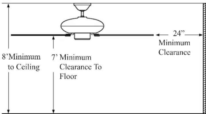
Figure 1
- Fan mounting height: Your Hunter fan comes with the proper hardware to hang the fan from a standard 8 foot ceiling so that the fan blades will be 12" from the ceiling and approximately 7 feet from the floor. See Figure 1.
NOTE: On vaulted ceilings, up to 45irc pitch, you must use the Hunter Vaulted Ceiling Mounting Kit.
Step 2: Inspect the Fan
- Unpack the fan carefully to avoid any damage to components.
!CAUTION!
- Never lift the motor by the wires. Let the motor rest in the carton liner for protection.
- Check the sack parts. See Figure 2.
Fan Parts
(Not Drawn to Scale)


Figure 2
Step 3: Installation of Ceiling Mounting Hardware
!CAUTION!
- Your Hunter ceiling fan weighs up to 50 lbs. The following precautions must be taken for safety, and to ensure that your fan is securely mounted to the ceiling.
- When inspecting or preparing the installation site where wiring is available, to avoid possible electrical shock, disconnect power by turning off the circuit breakers both to the outlet box and to its associated wall switch location. If you cannot lock the circuit breakers in the off position, securely fasten a prominent warning device, such as a tag, to the service panel.
- All wiring must be in accordance with national and local electrical codes. If you are unfamiliar with wiring, you should use a qualified electrician.
- Do not mount directly to an unsupported ceiling or to an electrical outlet box.
-
The wood joist chosen for mounting the fan must be sound and of sufficient size. In no case should it be smaller than standard 2"x4" lumber.
-
Secure a metallic outlet box 4" x 1-1/2" or 4" x 1/2" deep to a 2" x 4" cross brace between two ceiling joists as shown in Figure 3. The outletbox must be recessed in the ceiling by 1/16" minimum. Secure the outlet box to the cross brace by drilling two (2) pilot holes no larger than the minor diameter of the woodscrews (5/64") and use two #8 x 1-1/2" woodscrews and washers. Use the innermost holes for securing the box. Orient the box so the outermost holes are aligned with the 2" x 4" brace. The outermost holes will be use in Step 3 sub-step 2.
!CAUTION!
- Do not use a lubricant on the screws.

Figure 3
- Drill two (2) 1/4" diameter holes 2-9/16" apart through the back of the outlet box into the cross brace. There may be two holes at the correct spacing, but they will probably have to be enlarged.
- Use the two (2) bracket screws to secure the hanger bracket and canopy plate to the joist as shown in Figure 4. Install the rubber bumpers into the canopy plate and the rubber bushing in the hanger bracket before assembling the parts to the ceiling joist.
!CAUTION!
- Do not use a lubricant on the screws.

Figure 4
Step 4: Hanging the Fan
!CAUTIONS!
- Be sure to tighten the pipe nipple shown in Figure 2 into the fan, tighten the hanger bracket onto the pipe, and tighten the two set screws as described in sub-step 2 to prevent the fan from falling.
-
Your fan may weigh up to 50 lbs. All of the following steps must be followed in order to ensure a secure mounting. Perform sub-steps 1-4 with the motor resting in the liner for protection.
-
Take the hanger bracket from the sack parts and locate the pipe nipple (See Figure 2.). Feed the wires from the top of your motor through the pipe.
- Back out the set screw in the neck of the motor housing and the hanger bracket so the pipe can be screwed in. Screw the pipe into the fan until tight (at least 4-1/2 turns). Feed the wire through the canopy and the canopy insert and let the canopy rest on the neck of the motor. Slide the canopy insert over the pipe. Feed the wire through the hanger bracket and screw the hanger bracket onto the pipe until tight (at least 3 turns). Then use pliers to tighten both the hanger bracket and the pipe together. Tighten the set screw in the motor housing with pliers. Securely tighten the set screw in the hanger bracket. See Figure 5.

Figure 5
- Be sure the pin is centered in the rubber bushing. See Figures 6 and 7.
- Lift the fan by the motor housing and hook the hanger bracket onto the pin in the rubber bushing. Make sure both ends of the pin are outside the hanger bracket. See Figure 7.
!WARNING!
- Failure to perform these steps in the correct order may result in the fan falling.

Figure 6

natural_image
Technical line drawing of a mechanical assembly with no visible text or symbolsFigure 7
© 2003 HUNTER FAN CO. 41556-01 8/08/03
Step 5: Wiring Instructions
NOTE: Before you do the final wiring, you should decide
!WARNING!
- To avoid possible electrical shock, before wiring fan, disconnect power by turning off the circuit breakers both to the outlet box and to its associated wall switch location. If you cannot lock the circuit breakers in the "OFF" position, securely fasten a prominent warning device, such as a tag, to the service panel.
how you want to control your fan - with a pull cord, a wall switch or a speed control. At this point, you should also decide if you want to add a light adapter kit. Separate wiring instructions for Hunter accessories are included in the accessory packages.
- All wiring must be in accordance with national and local electrical codes. If you are unfamiliar with wiring, you should use a qualified electrician.
- Connect the black electrical supply lead to the black motor lead and the black with white stripe motor lead. (See Note below.)
- Connect the white electrical supply lead to the white motor lead.
- Connect the ground wire to the green screw on the side of the hanger bracket. See Figure 8. NOTE: If a separate wall switch will be used to control

natural_image
Pure mechanical diagram showing a lever mechanism with no text or symbolsFigure 8
a lighting accessory, connect the black wire with the white stripe to the wall switch lead, following the wiring instructions included with the accessory. The wall switch must be a listed general-use switch.
- After making the wire connections, the wires
!CAUTION!
- No bare wires or wire strands should be visible after making connections.
should be spread apart with the white and green wires on one side of the outlet box, and the black and black with white stripe wires on the other side of the box.
5. The splices should be turned upward and pushed carefully up into the outlet box.
Step 6: Lubrication
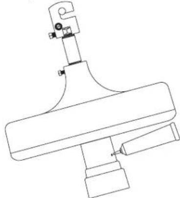
- Your fan has been shipped without oil in the motor. A tube of high grade SAE 10 non-detergent oil is packed in the sack parts. All of the oil in the tube must be put into the fan.
- Unscrew the oil hole screw on the side of the switch housing. See Figure 9.

- Cut the tip off the tube, tilt the fan motor as shown and place the tube into the oil hole of the switch housing. See Figure 10.
- Slowly put oil into the fan. All of the oil in the tube must be put into the fan.
- Reinstall the oil hole screw securely before moving the fan from the current (tilited) position to prevent oil from spilling from the oil hole..
natural_image
Technical line drawing of a mechanical assembly with no visible text or symbolsFigure 10
!CAUTION!
- Do not turn the fan on until lubrication has been added. To operate the fan without oil or with low oil will void your warranty.
This Lubrication System does not normally “use up” or require the addition of extra oil once the oil reservoir has been filled to the correct level. This unique lubrication system is one reason your Original Hunter Ceiling Fan will last a lifetime.
Canopy Installation
- Lift the canopy off the neck of the motor.
- Slide the canopy and canopy insert up until the three holes in the side of the canopy can be aligned with the three threaded holes in the canopy plate.
- Insert and tighten the three screws that hold the canopy in place. See Figure 11.

Figure 11
Step 7: Fan Blade Assembly and Installation
!WARNINGS!
• To reduce the rist of personal injury, do not bend the blade brackets when installing the blade brackets, balancing the blades, or cleaning the fan.
- Do not insert foreign objects in between rotating fan blades.
- Attach the wood blades to the blade brackets using three screws for each blade. See Figure 12.

natural_image
Technical line drawing of a mechanical assembly with mounting holes and a curved component (no text or symbols)Figure 12
- If your blades have large holes, you must first insert the rubber grommets into the holes. See Figure 13.
- Make sure that all screws are tight to prevent vibration or wobbling. A cavity in the styrofoam packaging has been provided to nest the parts in during assembly to assure correct alignment of parts.

Figure 13
NOTE: Grommets are usually assembled by hand. If you use a tool, make certain you do not damage the grommet or blade when inserting the grommets.
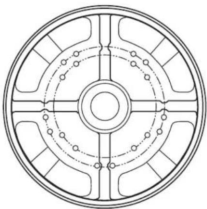
- With some fans you have an option to install four or five blades. For five blades, mount to the outer row of holes on the motor. For four blades, use the inner row. See Figure 14.
natural_image
Circular mechanical component diagram with symmetrical slots and central hub (no text or symbols)Figure 14
-
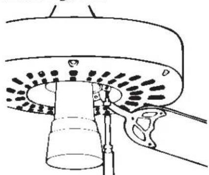
To install the blades to the motor, insert the blade iron screw through the hole in the blade iron. Use a screwdriver to hold in place.
-
Fasten the screw onto the motor, but do not overtighten. See Figure 15.
natural_image
Technical line drawing of a mechanical component with no visible text or symbolsFigure 15
- Line up the other hole on the motor and fasten the second screw.
NOTE: Before tightening the screws, make sure they are not cross-threaded in the mounting holes.
- Tighten both screws securely. Repeat for the remaining blades.
!CAUTION!
- Do not attempt to run the fan until all screws have been tightened securely.
- A blade balancing kit has been provided with your fan. Should the fan wobble in operation, you may use this kit to correct the balance per the instructions supplied with the kit.
Step 8: Operation of Your Hunter Fan
-
The operation of your fan is controlled with a pull-chain switch, which has four (4) positions: Off -- High -- Medium -- Low. Pull the chain gently to obtain the speed you desire.
-
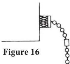
The Break-A-Way Connector is designed to separate from the chain at a predetermined force. If this separation occurs, simply reinsert the connector. It can be used again and again. See Figure 16.
- Reversing your fan is controlled by a small switch located on the switch housing. See Figure 17.
NOTE: Ceiling fans are usually adjusted once in the fall and again in the spring to blow upward in the winter and downward in the summer. You may run them in either direction at anytime, however, as you prefer. Experiment as you like to obtain maximum comfort from your fan.

natural_image
Simple line drawing of a funnel mounted on a base with a small oval cutout, no text or symbols present.Figure 17
Care and Maintenance
!CAUTION!
- Before performing any maintenance on the fan, disconnect the power to the fan.
Lubrication
Once properly installed, your fan needs little attention, beyond checking the oil level. The oil is checked by unscrewing and removing the oil hole screw. If oil comes out of the hole, the oil level is within proper levels.
If no oil comes out, complete the following steps:
- Reinstall the oil hole screw.
- Remove one blade iron/blade assembly from the motor housing by uninstalling the two blade armature screws.
- Rotate the motor so that the open area where the blade iron/blade assembly you just removed is directly above the oil hole screw. This is done so that there is enough room to properly position the tube of oil when refilling.
- Complete the steps in STEP 6: LUBRICATION to properly complete adding oil into the motor.
Cleaning
Take care when cleaning your fan. Never use an abrasive cleanser or brass polish. Use a damp cloth or sponge. Do not drip water or soap into the motor.
Blades should be wiped clean periodically to prevent dust buildup. Be careful not to bend the blade irons.
If blades are cracked or blade irons bent, do not attempt to repair them. Order replacement parts from your Hunter dealer.
Installation on Pitched Ceilings
Your Hunter Fan can be mounted onto a pitched ceiling (up to 34 degrees) using the same method as mounting on a flat ceiling, except that the hanger bracket and bushing must be aligned so they are pointing up the sloped of the ceiling. You will also need an extension pipe, which is available from your Hunter dealer.
Installation in Concrete Ceilings
!CAUTION!
- Your Hunter ceiling fan weighs up to 50 lbs. The following precautions must be taken for safety, and to ensure that your fan is securely mounted to the ceiling.
Refer to Figure 18 for the steps below.
- For concrete mounting, the drilled hole must be recommended by the manufacturer of the anchor and it must be drilled at least 1/2" deeper than the length of the anchor.
NOTE: The drilled hole is usually marked on the anchor.
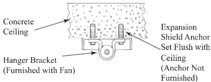
Figure 18
- The holes must be made with a suitable carbide-tipped masonry drill bit.
• The anchors must be new and unused. - The concrete ceiling must be sound and free of cracks or voids in the vicinity of the mounting holes.
- The anchors must be set in flush with the surface of the concrete.
- The bracket screws must never be backed out. If the bracket screws can be turned easily (by hand), do not hang the fan.
Installation
- Drill holes 2" deep in concrete ceiling to receive 1/4" x 1-1/2" expansion shield anchor, "Rawl No. 1055" or equal. (Not furnished.)
- Install shield in holes, observing all cautions above.
- Proceed with the installation of the fan per the basic installation instructions.
The Inside Story
Oil is constantly pumped up the spiral groove to lubricate the rotor and the shaft. The oil is returned to the reservoir where the bearings are submerged in a bath of oil.
This unique lubrication system is built into all Original® Hunter Ceiling Fans. That's one reason Hunters last so long, and why we can offer a Limited Lifetime Warranty.
Should you move you fan to another location, it is a good idea to check the oil reservoir. Hunter has developed an accessory “Original® Relocation Kit” that includes all mounting hardware and a fresh tube of oil for this reason. The model number is 22360.

natural_image
Cross-sectional diagram of a mechanical device with internal components and hands (no text or symbols)Figure 19
TROUBLESHOOTING
We appreciate the opportunity to supply you with the best ceiling fan available anywhere in the world.
Record the following information for your records and warranty assistance. Please refer to the carton and the Hunter nameplate (located on the top outside fan motor housing) for the proper information.
Model Name ____ Catalog No. ____ Serial No. ____
Date Purchased ____ Where Purchased ____
PROBLEM PROBABLE CAUSE
| Nothing happens; fan does not move. | 1. Power turned off, fuse blown, or circuit breaker tripped.2. Loose wire connections or wrong connections.3. Motor reversing switch not engaged.4. Pull chain switch not “on.”5. No oil or low oil level. | 1. Turn power on, replace fuse, or reset breaker.2. Loosen canopy, check all connections according to STEP 5 - WIRING INSTRUCTIONS (turn power off before checking).3. Push switch firmly up or down.4. Pull switch chain.5. Check the oil level according to STEP - CARE AND MAINTENANCE (turn fan off before checking.) |
| Note: If blades will not turn by hand, contact your nearest service representative or dealer for assistance. | ||
| Noisy operation. | 1. Blade brackets screwed loosely to motor.2. Blade screwed loosely to blade iron.3. Blade cracked.4. Canopy contacting ceiling.5. No oil or low oil level. | 1. Tighten screws until snug.2. Tighten screws until snug.3. Replace all blades.4. Lower canopy.5. Check the oil level according to STEP - CARE AND MAINTENANCE (turn fan off before checking.) |
| Excessive Wobbling | 1. Unbalanced blades.2. Inadequate blade clearance.3. Loose blades or blade irons.4. Fan not secure on hanger assembly. | 1. Rebalance. (See Step 7 sub-step 4.)2. Relocate Fan.3. Tighten all screws.4. Turn power off. Support fan very carefully. Loosen canopy and hang correctly. |
If you have tried these troubleshooting solutions and still have trouble, call 901-248-2222 or visit our Web site at http://www.hunterfan.com.

Hunter Fan Company 2500 Frisco Avenue Memphis, TN 38114 USA
©2001 Hunter Fan Co.
- !WARNINGS!
- !CAUTIONS!
- Installing Your Hunter® Ceiling Fan
- Step 1: Pre-Installation
- Step 2: Inspect the Fan
- !CAUTION!
- Step 3: Installation of Ceiling Mounting Hardware
- Step 4: Hanging the Fan
- !WARNING!
- Step 5: Wiring Instructions
- Step 6: Lubrication
- Canopy Installation
- Step 7: Fan Blade Assembly and Installation
- Step 8: Operation of Your Hunter Fan
- Care and Maintenance
- Lubrication
- Cleaning
- Installation on Pitched Ceilings
- Installation in Concrete Ceilings
- Installation
- The Inside Story
- TROUBLESHOOTING
Brand : HUNTER
Model : Outdoor Original 25602
Category : Household Fan