
ARK-1122 - Desktop computer Advantech - Free user manual and instructions
Find the device manual for free ARK-1122 Advantech in PDF.


| Product Type | Fanless Embedded Box PC |
| Processor | Intel Atom Dual Core N2600 1.6 GHz or N2800 1.86 GHz |
| Chipset | Intel NM10 Express |
| Memory | Up to 4 GB DDR3 1066 MHz SDRAM SODIMM |
| Display Interfaces | 1 x VGA, 1 x HDMI (up to 1920 x 1200) |
| Ethernet | 1 x GbE (ARK-1122H/C) or 2 x GbE (ARK-1122F) |
| USB Ports | 4 x USB 2.0 (ARK-1122H/C) or 3 x USB 2.0 (ARK-1122F) |
| Serial Ports | 1 x RS-232 (ARK-1122H/F) or 2 x RS-232 + 2 x RS-232/422/485 (ARK-1122C) |
| Audio | Line-in, Line-out (ALC892 codec) |
| Expansion Slots | 1 x half-size Mini-PCIe, 1 x full-size Mini-PCIe (ARK-1122F only) |
| Storage Options | 1 x 2.5" SATA HDD (9.5 mm height) and mSATA (ARK-1122H/C); SSD supported |
| Power Supply | DC 12V input, 3A adapter (36W) |
| Operating Temperature | -20 to 60°C (extended temp SSD) / 0 to 40°C (standard HDD) |
| Storage Temperature | -40 to 85°C |
| Relative Humidity | 95% @ 40°C (non-condensing) |
| Dimensions (W x H x D) | 133.8 x 43.1 x 94.2 mm (5.27" x 1.70" x 3.71") |
| Mounting Options | VESA, Desk, DIN-rail (with optional kit) |
| Cooling | Fanless, passive (sealed aluminum case) |
| Warranty | 2 years |
| Certifications | UL, CB, CCC, BSMI, CE, FCC Class A |
Frequently Asked Questions - ARK-1122 Advantech
User questions about ARK-1122 Advantech
0 question about this device. Answer the ones you know or ask your own.
Ask a new question about this device
Download the instructions for your Desktop computer in PDF format for free! Find your manual ARK-1122 - Advantech and take your electronic device back in hand. On this page are published all the documents necessary for the use of your device. ARK-1122 by Advantech.
USER MANUAL ARK-1122 Advantech
natural_image
Line drawing of a server rack with two views of the front panel and a computer tower, both without any text or symbols.ARK-1122
Fanless Embedded Box PC
Attention!
This package contains a hard-copy user manual in Chinese for China CCC certification purposes, and there is an English user manual included as a PDF file on the CD. Please disregard the printed Chinese copy of the user manual if the product is not to be sold and/or installed in China.
Copyright
The documentation and the software included with this product are copyrighted 2014 by Advantech Co., Ltd. All rights are reserved. Advantech Co., Ltd. reserves the right to make improvements in the products described in this manual at any time without notice. No part of this manual may be reproduced, copied, translated or transmitted in any form or by any means without the prior written permission of Advantech Co., Ltd. Information provided in this manual is intended to be accurate and reliable. However, Advantech Co., Ltd. assumes no responsibility for its use, nor for any infringements of the rights of third parties, which may result from its use.
Acknowledgements
Award is a trademark of Award Software International, Inc.
VIA is a trademark of VIA Technologies, Inc.
IBM, PC/AT, PS/2 and VGA are trademarks of International Business Machines Corporation.
Intel® and Pentium® are trademarks of Intel Corporation.
Microsoft Windows® is a registered trademark of Microsoft Corp.
RTL is a trademark of Realtek Semi-Conductor Co., Ltd.
ESS is a trademark of ESS Technology, Inc.
UMC is a trademark of United Microelectronics Corporation.
SMI is a trademark of Silicon Motion, Inc.
Creative is a trademark of Creative Technology LTD.
CHRONTEL is a trademark of Chrontel Inc.
All other product names or trademarks are properties of their respective owners.
For more information about this and other Advantech products, please visit our website at:
http://www.advantech.com/
http://www.advantech.com/ePlatform/
For technical support and service, please visit our support website at:
http://support.advantech.com.tw/support/
Part No. 200K112210 Edition 1
Printed in China January 2014
Product Warranty (2 years)
Advantech warrants to you, the original purchaser, that each of its products will be free from defects in materials and workmanship for two years from the date of purchase.
This warranty does not apply to any products which have been repaired or altered by persons other than repair personnel authorized by Advantech, or which have been subject to misuse, abuse, accident or improper installation. Advantech assumes no liability under the terms of this warranty as a consequence of such events.
Because of Advantech's high quality-control standards and rigorous testing, most of our customers never need to use our repair service. If an Advantech product is defective, it will be repaired or replaced at no charge during the warranty period. For out-of-warranty repairs, you will be billed according to the cost of replacement materials, service time and freight. Please consult your dealer for more details.
If you think you have a defective product, follow these steps:
- Collect all the information about the problem encountered. (For example, CPU speed, Advantech products used, other hardware and software used, etc.) Note anything abnormal and list any onscreen messages you get when the problem occurs.
- Call your dealer and describe the problem. Please have your manual, product, and any helpful information readily available.
- If your product is diagnosed as defective, obtain an RMA (return merchandise authorization) number from your dealer. This allows us to process your return more quickly.
- Carefully pack the defective product, a fully-completed Repair and Replacement Order Card and a photocopy proof of purchase date (such as your sales receipt) in a shippable container. A product returned without proof of the purchase date is not eligible for warranty service.
- Write the RMA number visibly on the outside of the package and ship it prepaid to your dealer.
Declaration of Conformity
FCC Class A
Note: This equipment has been tested and found to comply with the limits for a Class A digital device, pursuant to part 15 of the FCC Rules. These limits are designed to provide reasonable protection against harmful interference when the equipment is operated in a commercial environment. This equipment generates, uses, and can radiate radio frequency energy and, if not installed and used in accordance with the instruction manual, may cause harmful interference to radio communications. Operation of this equipment in a residential area is likely to cause harmful interference in which case the user will be required to correct the interference at his own expense.
Technical Support and Assistance
-
Visit the Advantech web site at www.advantech.com/support where you can find the latest information about the product.
-
Contact your distributor, sales representative, or Advantech's customer service center for technical support if you need additional assistance. Please have the following information ready before you call:
– Product name and serial number
– Description of your peripheral attachments
– Description of your software (operating system, version, application software, etc.)
– A complete description of the problem
- The exact wording of any error messages
Warnings, Cautions and Notes
Warning! Warnings indicate conditions, which if not observed, can cause personal injury!

Caution! Cautions are included to help you avoid damaging hardware or losing data.

Note! Notes provide optional additional information.

Safety Instructions
- Read these safety instructions carefully.
- Keep this User Manual for later reference.
- Disconnect this equipment from any AC outlet before cleaning. Use a damp cloth. Do not use liquid or spray detergents for cleaning.
-
For plug-in equipment, the power outlet socket must be located near the equipment and must be easily accessible.
-
Keep this equipment away from humidity.
-
Put this equipment on a reliable surface during installation. Dropping it or letting it fall may cause damage.
-
The openings on the enclosure are for air convection. Protect the equipment from overheating. DO NOT COVER THE OPENINGS.
-
Make sure the voltage of the power source is correct before connecting the equipment to the power outlet.
-
Position the power cord so that people cannot step on it. Do not place anything over the power cord.
-
All cautions and warnings on the equipment should be noted.
-
If the equipment is not used for a long time, disconnect it from the power source to avoid damage by transient overvoltage.
-
Never pour any liquid into an opening. This may cause fire or electrical shock.
-
Never open the equipment. For safety reasons, the equipment should be opened only by qualified service personnel.
-
If one of the following situations arises, get the equipment checked by service personnel:
■ The power cord or plug is damaged.
- Liquid has penetrated into the equipment.
■ The equipment has been exposed to moisture.
The equipment does not work well, or you cannot get it to work according to the user's manual.
■ The equipment has been dropped and damaged.
■ The equipment has obvious signs of breakage.
-
DO NOT LEAVE THIS EQUIPMENT IN AN ENVIRONMENT WHERE THE STORAGE TEMPERATURE MAY GO BELOW -20°C (-4°F) OR ABOVE 60°C (140°F). THIS COULD DAMAGE THE EQUIPMENT. THE EQUIPMENT SHOULD BE IN A CONTROLLED ENVIRONMENT.
-
CAUTION: DANGER OF EXPLOSION IF BATTERY IS INCORRECTLY REPLACED. REPLACE ONLY WITH THE SAME OR EQUIVALENT TYPE RECOMMENDED BY THE MANUFACTURER, DISCARD USED BATTERIES ACCORDING TO THE MANUFACTURER'S INSTRUCTIONS.
-
CAUTION: Any unverified component could cause unexpected damage. To ensure the correct installation, please always use the components (ex. screws) provided with the accessory box.
-
CAUTION: The computer is provided with a battery-powered real-time clock circuit. There is a danger of explosion if battery is incorrectly replaced. Replace only with same or equivalent type recommended by the manufacture. Discard used batteries according to the manufacturers instructions.
-
CAUTION: Always completely disconnect the power cord from your chassis whenever you work with the hardware. Do not make connections while the power is on. Sensitive electronic components can be damaged by sudden power surges.
The sound pressure level at the operator's position according to IEC 704-1:1982 is no more than 70 dB (A).
DISCLAIMER: This set of instructions is given according to IEC 704-1. Advantech disclaims all responsibility for the accuracy of any statements contained herein.
Packing list
Before installation, please ensure the following items have been shipped:
1 x ARK-1122 unit
1 x Driver/Utility CD
■ 1 x DC 12V Power Adapter
■ 1 x Chinese user manual
1 x China RoHS
■ 1 x 2-year warranty card
Ordering Information
Model Number Description
| ARK-1122H-S6A1E | Intel® AtomTM N2600 1.6 GHz w/ VGA + HDMI dual display |
| ARK-1122C-S6A1E | Intel® AtomTM N2600 1.6 GHz w/ 4 COM + Wi-Fi expansion |
| ARK-1122F-S8A1E | Intel® AtomTM N2800 1.86 GHz w/ 2 Gbe LAN + 3 G Expansion |
Optional Accessories
Part Number Description
| 1700001524 Power Cable 3-pin 180 cm, USA Type |
| 170203183C Power Cable 3-pin 180 cm, Europe Type |
| 170203180A Power Cable 3-pin 180 cm, UK Type |
| 1700008921 Power Cable 3-pin 180 cm, PSE Mark |
| 1960052227N001 VESA/Desk mounting plate for ARK-1122 |
| 9666112000E DIN Rail mounting kits for ARK-112X series |
Contents
Chapter 1 General Introduction ......1
1.1 Introduction 2
1.2 Features 2
1.3 Specifications 2
1.3.1 General 2
1.3.2 Display 3
1.3.3 Ethernet 3
1.3.4 Power Consumption.... 3
1.3.5 Power Requirement 3
1.4 Environmental Specifications 3
1.5 Mechanical Specifications.... 4
1.5.1 ARK-1122H Dimensions 4
Figure 1.1 ARK-1122H mechanical dimension drawing ..... 4
1.5.2 ARK-1122C Dimensions 5
Figure 1.2 ARK-1122C mechanical dimension drawing ..... 5
1.5.3 ARK-1122F Dimensions 6
Figure 1.3 ARK-1122F mechanical dimension drawing....6
Chapter 2 Hardware installation ....7
2.1 Introduction 8
2.2 Jumpers 8
2.2.1 Jumper list....8
Table 2.1: Jumper List 8
2.2.2 Jumper Settings 8
Table 2.2: J1: AT / ATX Power Selection 8
2.2.3 Jumper Description 8
2.3 ARK-1122 I/O Indication 9
Figure 2.1 ARK-1122H front view 9
Figure 2.2 ARK-1122H rear view....9
Figure 2.3 ARK-1122C front view 10
Figure 2.4 ARK-1122C rear view.... 10
Figure 2.5 ARK-1122F front view 11
Figure 2.6 ARK-1122F rear view 11
2.4 ARK-1122H External I/O Connectors.... 12
2.4.1 Power ON/OFF Button.... 12
Figure 2.7 Power ON/OFF Button 12
2.4.2 Power Input Connector 12
Figure 2.8 Power Input Connector.... 12
2.4.3 Ethernet Connector (LAN) 12
Figure 2.9 Ethernet Connector 12
Table 2.3: Ethernet Connector Pin Assignments.... 12
2.4.4 VGA Connector.... 13
Figure 2.10 VGA Connector 13
Table 2.4: VGA Connector Pin Assignments.... 13
2.4.5 USB Connectors 13
Figure 2.11 USB Connector.... 13
Table 2.5: USB Connector Pin Assignments.... 13
2.4.6 Audio Connector 14
Figure 2.12 Audio Connector.... 14
Table 2.6: DIO Connector Pin Assignments.... 14
2.4.7 COM Connector 14
Figure 2.13 COM Port Connector 14
Table 2.7: COM Connector Pin Assignments.... 14
2.4.8 HDMI Connector 15
Figure 2.14 HDMI Connector.... 15
2.5 ARK-1122C External I/O Connectors 15
2.5.1 Power ON/OFF Button.... 15
Figure 2.15 Power ON/OFF Button 15
2.5.2 Power Input Connector 15
Figure 2.16 Power Input Connector.... 15
2.5.3 Ethernet Connector (LAN) 15
Figure 2.17 Ethernet Connector 15
Table 2.8: Ethernet Connector Pin Assignments ..... 16
2.5.4 VGA Connector.... 16
Figure 2.18 VGA Connector 16
Table 2.9: VGA Connector Pin Assignments ..... 16
2.5.5 USB Connectors 17
Figure 2.19 USB Connector 17
Table 2.10:USB Connector Pin Assignments.... 17
2.5.6 Audio Connector 17
Figure 2.20 Audio Connector.... 17
Table 2.11:DIO Connector Pin Assignments.... 17
2.5.7 COM Connector.... 18
Figure 2.21 COM Port Connector.... 18
Table 2.12:COM Connector Pin Assignments.... 18
2.6 ARK-1122F External I/O Connectors.... 19
2.6.1 Power ON/OFF Button.... 19
Figure 2.22 Power ON/OFF Button 19
2.6.2 Power Input Connector 19
Figure 2.23 Power Input Connector.... 19
2.6.3 Ethernet Connector (LAN) 19
Figure 2.24 Ethernet Connector 19
Table 2.13:Ethernet Connector Pin Assignments ..... 19
2.6.4 VGA Connector.... 20
Figure 2.25 VGA Connector 20
Table 2.14: VGA Connector Pin Assignments ..... 20
2.6.5 USB Connectors 20
Figure 2.26 USB Connector 20
Table 2.15:USB Connector Pin Assignments.... 20
2.6.6 Audio Connector 21
Figure 2.27 Audio Connector.... 21
Table 2.16:DIO Connector Pin Assignments.... 21
2.6.7 COM Connector.... 21
Figure 2.28 COM Port Connector.... 21
Table 2.17:COM Connector Pin Assignments.... 21
2.6.8 HDMI Connector 22
Figure 2.29 HDMI Connector.... 22
2.6.9 SIM Card Holder 22
Figure 2.30 SIM Card Holder.... 22
2.7 Peripheral Installation 22
2.7.1 HDD Installation (ARK-1122H only).... 22
2.7.2 mSATA HD Installation 25
2.7.3 RAM Installation.... 27
Chapter 3 BIOS Settings 29
3.1 Introduction ...... 30
Figure 3.1 Setup program initial screen.... 30
3.2 Entering Setup 31
3.2.1 Main Setup.... 31
Figure 3.2 Main Setup Screen.... 31
3.2.2 Advanced BIOS Features Setup.... 32
Figure 3.3 Advanced BIOS Features Setup Screen 32
Figure 3.4 ACPI Setting 33
Figure 3.5 CPU Configuration Settings.... 34
Figure 3.6 IDE Configuration 35
Figure 3.7 Intel Fast Flash Standby.... 36
Figure 3.8 USB Configuration.... 37
Figure 3.9 Super IO Configuration.... 38
Figure 3.10 H/W Monitor.... 39
Figure 3.11 AOAC Configuration 40
Figure 3.12 PPM Configuration 41
3.2.3 Chipset.... 42
Figure 3.13 Chipset Setup 42
Figure 3.14 Chipset Setup 42
Figure 3.15 Chipset Setup 43
3.2.4 Boot.... 44
Figure 3.16 Boot Setup.... 44
3.2.5 Security Settings 45
Figure 3.17 Security Setup 45
3.2.6 Save & Exit 46
Figure 3.18 Save & Exit Setup.... 46
Appendix A WDT & GPIO Sample Code .....49
A.1 Watchdog Timer Sample Code 50
Chapter 1
General Introduction
This chapter gives background information on ARK-1122 series.
1.1 Introduction
The ARK-1122 fanless Embedded Box Computer is an ideal, application-ready system platform solution. All electronics are protected in a compact, sealed, aluminum case for easy embedding in the customer's own housing, or as a stand-alone application where space is limited and the environment harsh.
The solid, sealed aluminum case offers vibration and dust resistance while also providing a passive cooling solution. The ARK-1122 provides system integrators with a turn-key solution and versatile application development path without breaking the bank or missing time-to-market deadlines.
ARK-1122 is designed as a palm-size fanless embedded system and occupies only 133.8 x 43.1 x 94.2 mm (5.27" x 1.70" x 3.71"). The rugged, cast aluminum case not only provides great protection from EMI, shock/vibration, cold and heat, but also passive cooling for quiet, fanless operation. ARK-1122 meets demands by offering up to 1 x VGA, 1 x HDMI, 2 x Giga LAN, 4 x USB 2.0 ports, and 4 x COM ports (by SKU); all packed into a compact rugged unit and powered by an Intel® Atom™ N2600/N2800 processor. ARK-1122 also supports both 2.5" SATA HDD, mSATA and SSD for storage options (by SKU) even though it is a palm-size system. Besides, ARK-1122 is a low-power-consumption system and it is powered by DC 12 V input. The ARK-1122 provides for diversified application fields.
1.2 Features
Key features
Extremely compact, sealed construction with fanless operation, supports Intel® Atom™ N2600 1.6 GHz / N2800 1.86 GHz CPU
Ultra slim palm-size system with 2.5" SATA HDD/SSD/mSATA support (by SKU)
■ Low power consumption system
■ Support VESA/desk/DIN-rail mountings
1.3 Specifications
1.3.1 General
CPU: Intel® Atom™ Dual Core Processor N2600 1.6 GHz/N2800 1.86 GHz
System Chipset: Intel® NM10 Express Chipset
BIOS: AMI 16 Mbit Flash BIOS
System Memory: Up to 4G DD3 1066GHz SDRAM SODIMM
■ Watchdog Timer: 255-level interval timer, setup by software
Serial Ports:
- 1 x RS232 (for ARK-1122H & ARK-1122F)
- 2 x RS-232, 2 x RS-232/422/485 with auto flow control (for ARK-1122C)
USB:
- 4 x USB 2.0 compliant Ports (for ARK-1122H & ARK-1122C)
- 3 x USB 2.0 compliant Ports (for ARK-1122F)
■ Audio: High Definition Audio Codec - Realtek ALC892, with Line-in, Line-out (ARK-1122H & ARK-1122F)
■ Expansion Interface: Support up to 1 x half size Mini-PCIe & 1 x full size Mini-PCIe (ARK-1122F only)
Storage:
- Supports SSD or 1 x 2.5" SATAII HDD (9.5 mm height only)
– Support mSATA HDD device
- SATA: Support 1 x 2.5" SATAII HDD (9.5 mm height only)
1.3.2 Display
Chipset: Intel® Atom N2600/N2800
■ Display Memory: Intel® NM10 Express Chipset
■ VGA Resolution: Supports up to 1920 x 1200 HDMI
1.3.3 Ethernet
Chipset: Intel® 82567V
■ Speed: 10/100/1000 Mbps, support Wake on LAN
■ Interface: Up to 2 x RJ45 (ARK-1122F)
Standard: Compliant with IEEE 802.3, IEEE 802.3u, IEEE 802.3x, IEEE 8023y, IEEE 802.ab.
1.3.4 Power Consumption
■ Input Voltage: DC 12V
■ Power Adapter: AC to DC 12 V/3 A, 36 W
1.3.5 Power Requirement
System power:
– Minimum power input: DC 12 V 1.5 A
■ RTC battery: 3 V/210 mAh
1.4 Environmental Specifications
Operating temperature: -20 \~ 60° C (With extended temperature SSD/mSATA devices) & 0 \~ 40° C (With standard temperature HDD/SSD/mSATA devices)
■ Relative humidity: 95% @ 40°C (non-condensing)
■ Storage temperature: -40 \~ 85°C (-40 \~ 185°F)
Vibration loading during operation:
- With SSD/mSATA: 3 Grms, IEC 60068-2-64, random, 5 \~ 500 Hz, 1 hr/axis
■ Shock during operation:
- With SSD/mSATA: 30 G, IEC 60068-2-64, half sine, 11 ms duration
Safety: UL,CB,CCC,BSMI
■ EMC: CE, FCC Class A, BSMI, CCC
1.5 Mechanical Specifications
1.5.1 ARK-1122H Dimensions
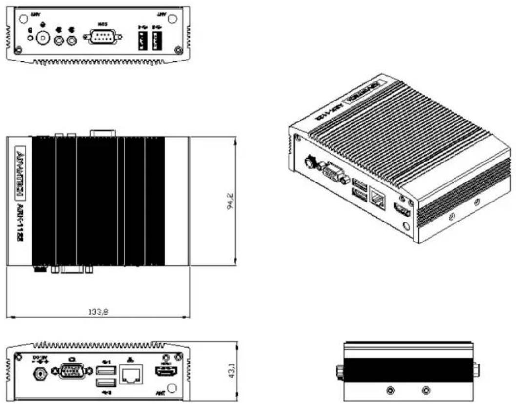
Figure 1.1 ARK-1122H mechanical dimension drawing
1.5.2 ARK-1122C Dimensions
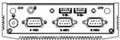
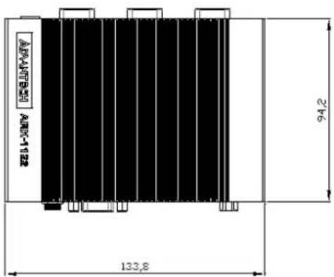
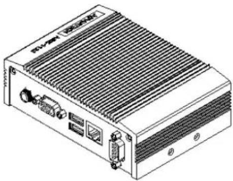
natural_image
Isometric line drawing of a portable electronic device with ventilation grilles and ports (no text or symbols)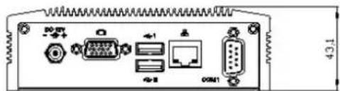
natural_image
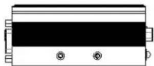
Pure electrical circuit lines without any symbolsFigure 1.2 ARK-1122C mechanical dimension drawing
1.5.3 ARK-1122F Dimensions
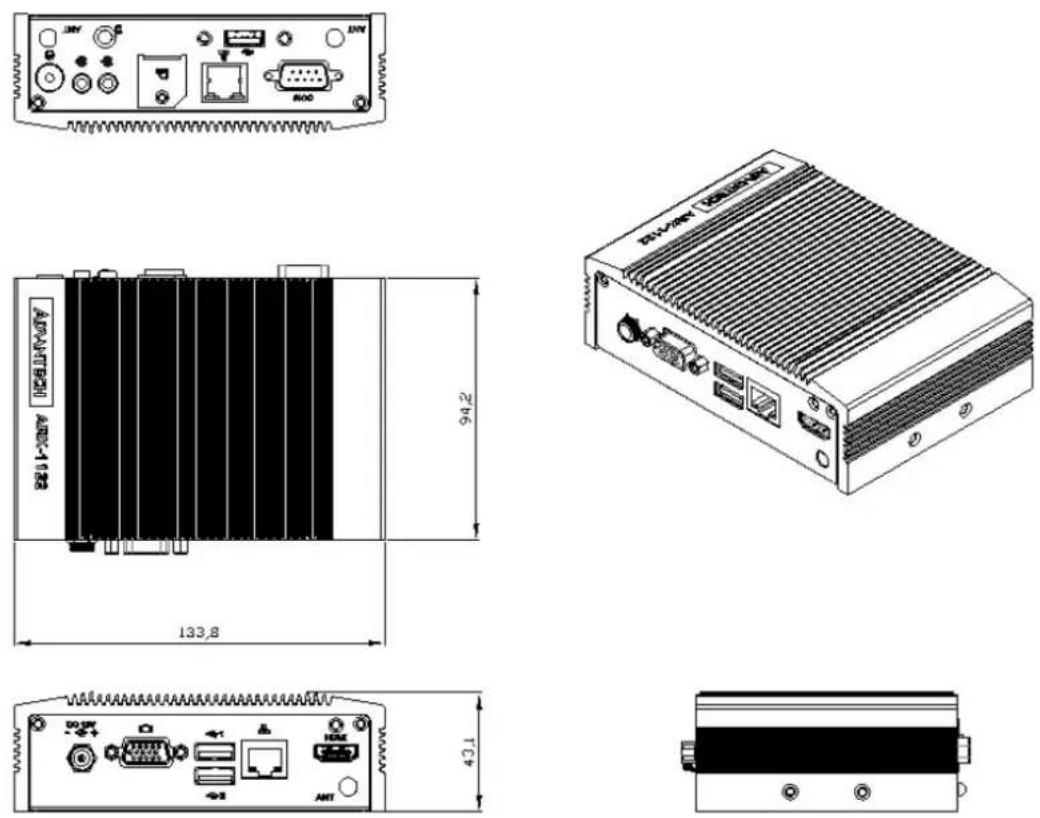
Figure 1.3 ARK-1122F mechanical dimension drawing
Chapter 2
Hardware installation
This chapter introduces external IO and the installation of ARK-1122 Hardware.
2.1 Introduction
The following sections show the internal jumper settings and the external connectors and pin assignments for applications.
2.2 Jumpers
2.2.1 Jumper list
Table 2.1: Jumper List
| J1 | AT / ATX Power Selection |
2.2.2 Jumper Settings
Table 2.2: J1: AT / ATX Power Selection
| Part Number 1653003260 | |
| Footprint HD_3x2P_79 | |
| Description | PIN HEADER 3*2P 180D(M) 2.0mm SMD SOUARE PIN |
| Setting Function | |
| (5-6) ON AT power | |
| *(5-6) Empty ATX power | |
* Default setting
2.2.3 Jumper Description
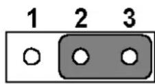
Cards can be configured by setting jumpers. A jumper is a metal bridge used to close an electric circuit. It consists of two metal pins and a small metal clip (often protected by a plastic cover) that slides over the pins to connect them. To close a jumper, you connect the pins with the clip. To open a jumper, you remove the clip. Sometimes a jumper will have three pins, labeled 1, 2 and 3. In this case you would connect either pins 1 and 2, or 2 and 3.
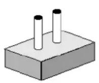
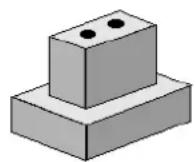
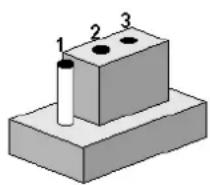
The jumper settings are schematically depicted in this manual as follows.
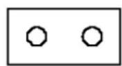
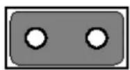
A pair of needle-nose pliers may be helpful when working with jumpers. If you have any doubts about the best hardware configuration for your application, contact your local distributor or sales representative before you make any changes.
Generally, you simply need a standard cable to make most connections.
Warning! To avoid damaging the computer, always turn off the power supply before setting jumpers or clearing CMOS. Before turning on the power supply, make sure CMOS jumper is back to 3.0 V Battery On.
2.3 ARK-1122 I/O Indication
ARK-1122H
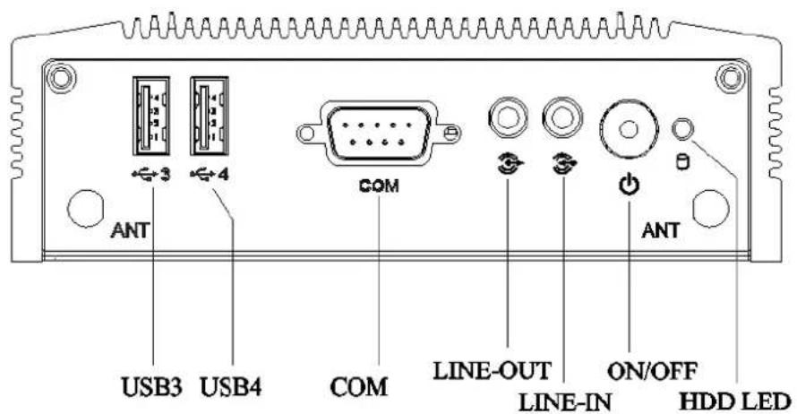
Figure 2.1 ARK-1122H front view
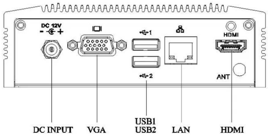
Figure 2.2 ARK-1122H rear view
ARK-1122C
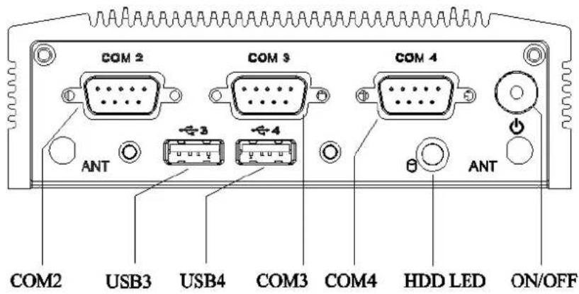
Figure 2.3 ARK-1122C front view
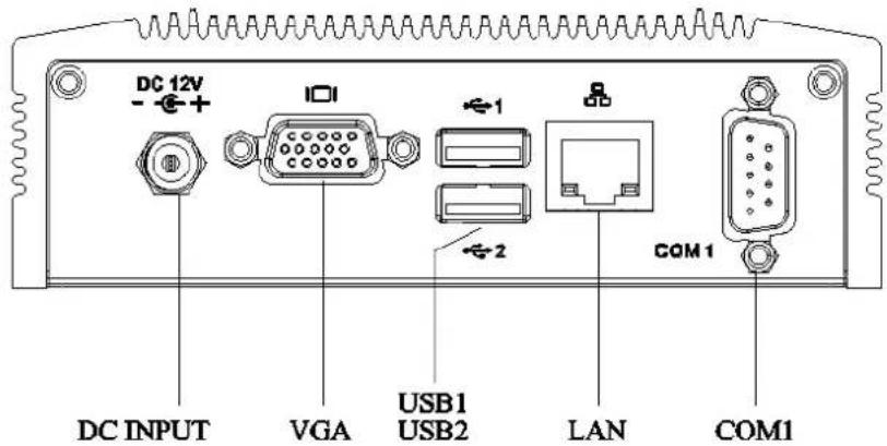
Figure 2.4 ARK-1122C rear view
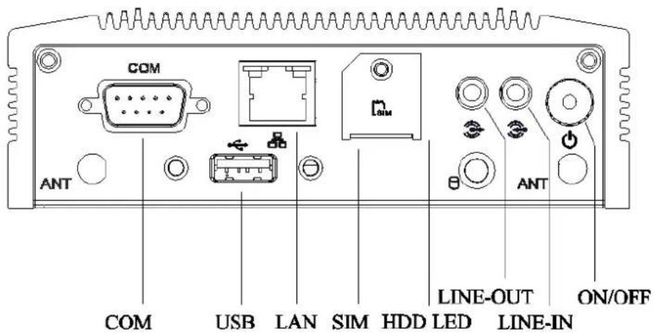
Figure 2.5 ARK-1122F front view
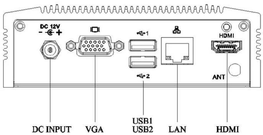
Figure 2.6 ARK-1122F rear view
2.4 ARK-1122H External I/O Connectors
2.4.1 Power ON/OFF Button
ARK-1122H comes with a Power On/Off button with LED indicators on the front side to show its On status (Green LED) and Off/Suspend status (Orange LED). Dual functions of Soft Power -On/Off (Instant off or Delay 4 Seconds), and Suspend are supported.

Figure 2.7 Power ON/OFF Button
2.4.2 Power Input Connector
ARK-1122H comes with a DC-Jack header that carries 12 V_DC external power input. The bracket makes the power connector very secure.
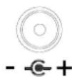
Figure 2.8 Power Input Connector
2.4.3 Ethernet Connector (LAN)
ARK-1122H provides one RJ45 LAN interface connector which is fully compliant with IEEE 802.3u 10/100/1000 Mbps CSMA/CD standards. It is equipped with 82567V and support Wake on LAN. The Ethernet port uses a standard RJ-45 jack connector with LED indicators on the front side to show Active/Link status and Speed status.
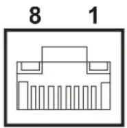
Figure 2.9 Ethernet Connector
Table 2.3: Ethernet Connector Pin Assignments
| Pin 10/100/1000 Mbps Signal Name | |||
| 1 TX+, MDI0+ | |||
| 2 | T | X | - |
| 3 | R | X | + |
| 4 | M | D | I |
| 5 | M | D | I |
| 6 | R | X | - |
| 7 | M | D | I |
| 8 | M | D | I |
Note!NC, if present, means "No Connection".

2.4.4 VGA Connector
The ARK-1122H provides a high resolution VGA interface connected by a D-sub 15-pin connector to support a VGA CRT monitor. It supports display resolution up to 1920 x 1200 HDMI.
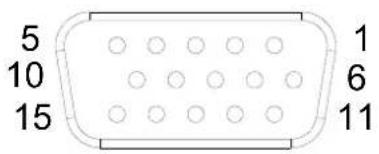
Figure 2.10 VGA Connector
Table 2.4: VGA Connector Pin Assignments
| Pin Signal Name Pin Signal Name | |||||
| 1 Red 2 Green | |||||
| 3 Blue 4 NC | |||||
| 5 GND 6 GND | |||||
| 7 GND 8 GND | |||||
| 9 | N | C | 1 | 0 | G |
| 11 | NC | 12 | DDC Date | ||
| 13 | H-SYNC | 14 | V-SYNC | ||
| 15 | DDC Clock | ||||
2.4.5 USB Connectors
The ARK-1122H provides four USB interface connectors, which give complete Plug & Play and hot swapping for up to 127 external devices. The USB interface is compliant with USB UHCI, Rev. 2.0. The USB interface supports Plug and Play, which enables you to connect or disconnect a device whenever you want, without turning off the computer.
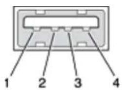
Figure 2.11 USB Connector
Table 2.5: USB Connector Pin Assignments
| Pin Signal Name | Pin Signal Name | ||
| 1 | VCC | 2 | USB_data- |
| 3 | USB_data+ | 4 | GND |
2.4.6 Audio Connector
ARK-1122H offers stereo audio ports by two 3.5 ear phone jack connectors of Line_out and Line_in. The audio chip controller is ALC892 which is compliant with the Azalea standard.
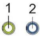
Figure 2.12 Audio Connector
Table 2.6: DIO Connector Pin Assignments
| Pin Signal Name |
| 1 Line-out |
| 2 Line-in |
2.4.7 COM Connector
ARK-1122H provides one D-sub 9-pin connectors, which offers RS-232 serial communication interface.
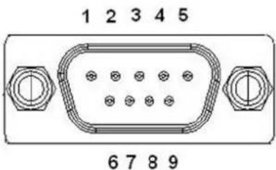
Figure 2.13 COM Port Connector
Table 2.7: COM Connector Pin Assignments
| RS-232 RS-422 RS-485 | |||
| Pin Signal Name Signal Name Signal Name | |||
| 1 | DCD | Tx- | DATA- |
| 2 | RxD | Tx+ | DATA+ |
| 3 | TxD | Rx+ | NC |
| 4 | DTR | Rx- | NC |
| 5 | GND | GND | GND |
| 6 | DSR | NC | NC |
| 7 | RTS | NC | NC |
| 8 | CTS | NC | NC |
| 9 | RI | NC | NC |
Note! NC means "No Connection".

2.4.8 HDMI Connector
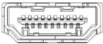
An integrated, 19-pin receptacle connector HDMI Type A Interface is provided. The HDMI link supports resolutions up to 1920x1200 @ 60 Hz.
natural_image
Technical line drawing of a connector housing (no text or symbols)Figure 2.14 HDMI Connector
2.5 ARK-1122C External I/O Connectors
2.5.1 Power ON/OFF Button
ARK-1122C comes with a Power On/Off button with LED indicators on the front side to show its On status (Green LED) and Off/Suspend status (Orange LED). Dual functions of Soft Power -On/Off (Instant off or Delay 4 Seconds), and Suspend are supported.

Figure 2.15 Power ON/OFF Button
2.5.2 Power Input Connector
ARK-1122C comes with a DC-Jack header that carries 12 VDC external power input. The bracket makes the power connector very secure.
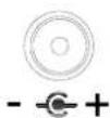
Figure 2.16 Power Input Connector
2.5.3 Ethernet Connector (LAN)
ARK-1122C provides one RJ45 LAN interface connector which is fully compliant with IEEE 802.3u 10/100/1000 Mbps CSMA/CD standards. It is equipped with 82567V and support Wake on LAN. The Ethernet port uses a standard RJ-45 jack connector with LED indicators on the front side to show Active/Link status and Speed status.
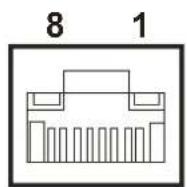
Figure 2.17 Ethernet Connector
Table 2.8: Ethernet Connector Pin Assignments
Pin 10/100/1000 Mbps Signal Name
| 1 TX+, MDI0+ | |||
| 2 | T | X | - |
| 3 | R | X | + |
| 4 | M | D | I |
| 5 | M | D | I |
| 6 | R | X | - |
| 7 | M | D | I |
| 8 | M | D | I |
Note!NC, if present, means "No Connection".

2.5.4 VGA Connector
The ARK-1122C provides a high resolution VGA interface connected by a D-sub 15-pin connector to support a VGA CRT monitor. It supports display resolution up to 1920 x 1200 HDMI.
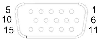
Figure 2.18 VGA Connector
Table 2.9: VGA Connector Pin Assignments
Pin Signal Name Pin Signal Name
| 1 | R | e | d | 2 | G | ||
| 3 Blue | 4 | NC | |||||
| 5 GND | 6 | GND | |||||
| 7 GND | 8 | GND | |||||
| 9 | N | C | 1 | 0 | G | ||
| 11 | NC | 12 | DDC Date | ||||
| 13 | H-SYNC | 14 | V-SYNC | ||||
| 15 | DDC Clock | ||||||
2.5.5 USB Connectors
The ARK-1122C provides up to four USB interface connectors, which give complete Plug & Play and hot swapping for up to 127 external devices. The USB interface is compliant with USB UHCI, Rev. 2.0. The USB interface supports Plug and Play, which enables you to connect or disconnect a device whenever you want, without turning off the computer.
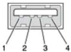
Figure 2.19 USB Connector
Table 2.10: USB Connector Pin Assignments
| Pin Signal Name Pin Signal Name | ||||||
| 1 | V | C | C | 2 | U | |
| 3 | U | S | B | _ | d | a |
2.5.6 Audio Connector
ARK-1122C offers stereo audio ports by two 3.5??ear phone jack connectors of Line_out and Line_in. The audio chip controller is ALC892 which is compliant with the Azalea standard.
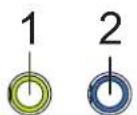
Figure 2.20 Audio Connector
Table 2.11: DIO Connector Pin Assignments
| Pin Signal Name |
| 1 Line-out |
| 2 Line-in |
2.5.7 COM Connector
ARK-1122C provides four D-sub 9-pin connectors, which offers two RS-232 serial communication interface and two RS-232/422/485 serial communication interface. Default setting is RS-232, and the mode of serial ports are controlled by relay IC. If you would like to use RS-422/485, just need change the BIOS setting. You can find detailed BIOS setting for serial ports in Chapter 3.
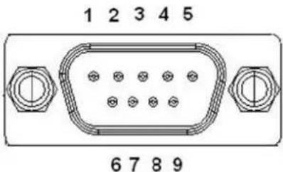
Figure 2.21 COM Port Connector
Table 2.12: COM Connector Pin Assignments
| RS-232 RS-422 RS-485 | |||
| Pin Signal Name Signal Name Signal Name | |||
| 1 | DCD | Tx- | DATA- |
| 2 | RxD | Tx+ | DATA+ |
| 3 | TxD | Rx+ | NC |
| 4 | DTR | Rx- | NC |
| 5 | GND | GND | GND |
| 6 | DSR | NC | NC |
| 7 | RTS | NC | NC |
| 8 | CTS | NC | NC |
| 9 | RI | NC | NC |
Note! NC means "No Connection".

2.6 ARK-1122F External I/O Connectors
2.6.1 Power ON/OFF Button
ARK-1122F comes with a Power On/Off button with LED indicators on the front side to show its On status (Green LED) and Off/Suspend status (Orange LED). Dual functions of Soft Power -On/Off (Instant off or Delay 4 Seconds), and Suspend are supported.

Figure 2.22 Power ON/OFF Button
2.6.2 Power Input Connector
ARK-1122F comes with a DC-Jack header that carries 12 VDC external power input. The bracket makes the power connector very secure.
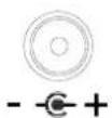
Figure 2.23 Power Input Connector
2.6.3 Ethernet Connector (LAN)
ARK-1122F provides two RJ45 LAN interface connector which is fully compliant with IEEE 802.3u 10/100/1000 Mbps CSMA/CD standards. It is equipped with 82567V and support Wake on LAN. The Ethernet port uses a standard RJ-45 jack connector with LED indicators on the front side to show Active/Link status and Speed status.
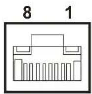
Figure 2.24 Ethernet Connector
Table 2.13: Ethernet Connector Pin Assignments
| Pin 10/100/1000 Mbps Signal Name | |||
| 1 | T | X | + |
| 2 TX-, MDI0- | |||
| 3 RX+, MDI1+ | |||
| 4 | M | D | I |
| 5 | M | D | I |
| 6 | R | X | - |
| 7 | M | D | I |
| 8 | M | D | I |
Note!NC, if present, means "No Connection".

2.6.4 VGA Connector
The ARK-1122F provides a high resolution VGA interface connected by a D-sub 15-pin connector to support a VGA CRT monitor. It supports display resolution up to 1920 x 1200 HDMI.
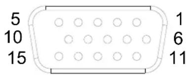
Figure 2.25 VGA Connector
Table 2.14: VGA Connector Pin Assignments
Pin Signal Name Pin Signal Name
| 1 | R | e | d | 2 | G | ||
| 3 Blue 4 NC | |||||||
| 5 GND 6 GND | |||||||
| 7 GND 8 GND | |||||||
| 9 | N | C | 1 | 0 | G | N | |
| 11 | NC | 12 | DDC Date | ||||
| 13 | H-SYNC | 14 | V-SYNC | ||||
| 15 | DDC Clock | ||||||
2.6.5 USB Connectors
The ARK-1122F provides three USB interface connectors, which give complete Plug & Play and hot swapping for up to 127 external devices. The USB interface is compliant with USB UHCI, Rev. 2.0. The USB interface supports Plug and Play, which enables you to connect or disconnect a device whenever you want, without turning off the computer.
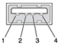
Figure 2.26 USB Connector
Table 2.15: USB Connector Pin Assignments
| Pin Signal Name | Pin Signal Name | |
| 1 VCC | 2 | USB_data- |
| 3 USB_data+ | 4 GND | |
2.6.6 Audio Connector
ARK-1122F offers stereo audio ports by two 3.5 ear phone jack connectors of Line_out and Line_in. The audio chip controller is ALC892 which is compliant with the Azalea standard.
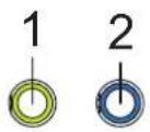
Figure 2.27 Audio Connector
Table 2.16: DIO Connector Pin Assignments
| Pin Signal Name |
| 1 Line-out |
| 2 Line-in |
2.6.7 COM Connector
ARK-1122F provides one D-sub 9-pin connectors, which offers RS-232 serial communication interface.
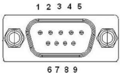
Figure 2.28 COM Port Connector
Table 2.17: COM Connector Pin Assignments
| RS-232 RS-422 RS-485 | |||
| Pin Signal Name Signal Name Signal Name | |||
| 1 | DCD | Tx- | DATA- |
| 2 | RxD | Tx+ | DATA+ |
| 3 | TxD | Rx+ | NC |
| 4 | DTR | Rx- | NC |
| 5 | GND | GND | GND |
| 6 | DSR | NC | NC |
| 7 | RTS | NC | NC |
| 8 | CTS | NC | NC |
| 9 | RI | NC | NC |
Note! NC means "No Connection".

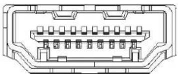
2.6.8 HDMI Connector
An integrated, 19-pin receptacle connector HDMI Type A Interface is provided. The HDMI link supports resolutions up to 1920 x 1200 @ 60 Hz.
natural_image
Technical line drawing of an electrical connector housing (no text or symbols)Figure 2.29 HDMI Connector
2.6.9 SIM Card Holder
ARK-1122F provides a SIM card Holder for internet connection.
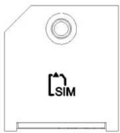
Figure 2.30 SIM Card Holder
2.7 Peripheral Installation
2.7.1 HDD Installation (ARK-1122H only)
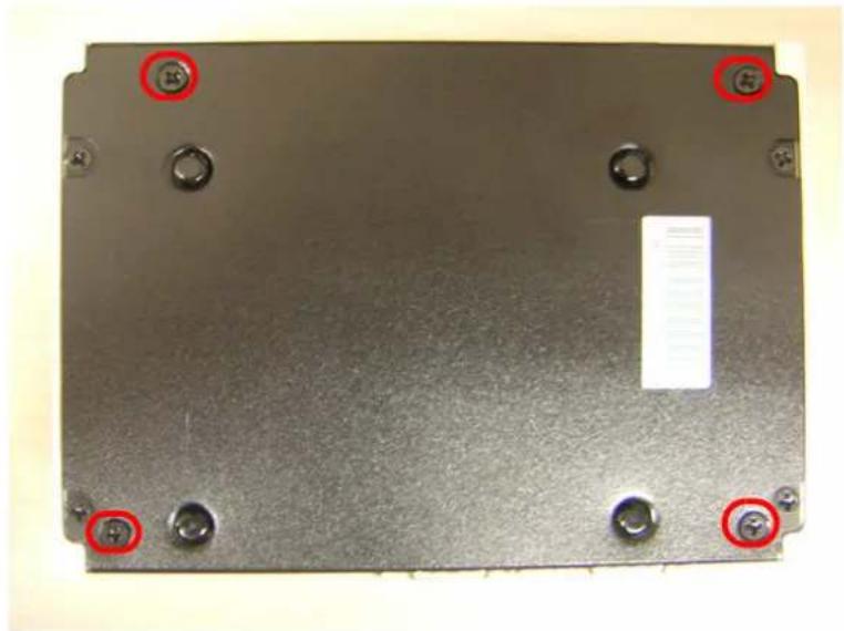
- Unscrew the bottom cover screws. (marked with "HDD")
natural_image
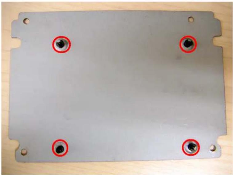
Metallic electronic component with four mounting holes and red circular annotations (no readable text or symbols)- Remove the four SNAP RIVETs from the bottom cover.
natural_image
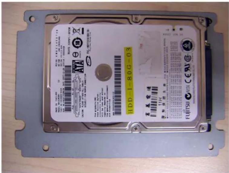
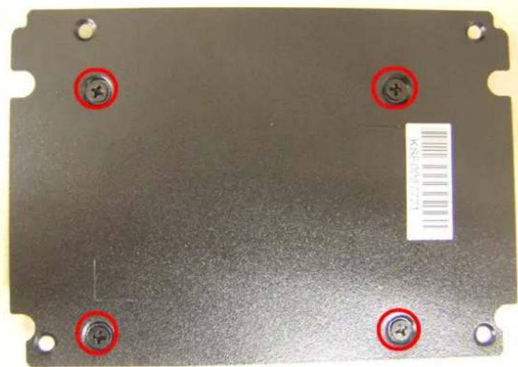
Metal plate with four circular red-circled holes on a wooden surface (no text or symbols)- Secure 2.5" SATA HDD onto the bottom cover. The screws are in the accessory box.
natural_image
Metallic electronic component with four mounting holes and red circular annotations (no readable text or symbols)- Connect SATA signal and power cable to the 2.5" SATA HDD.
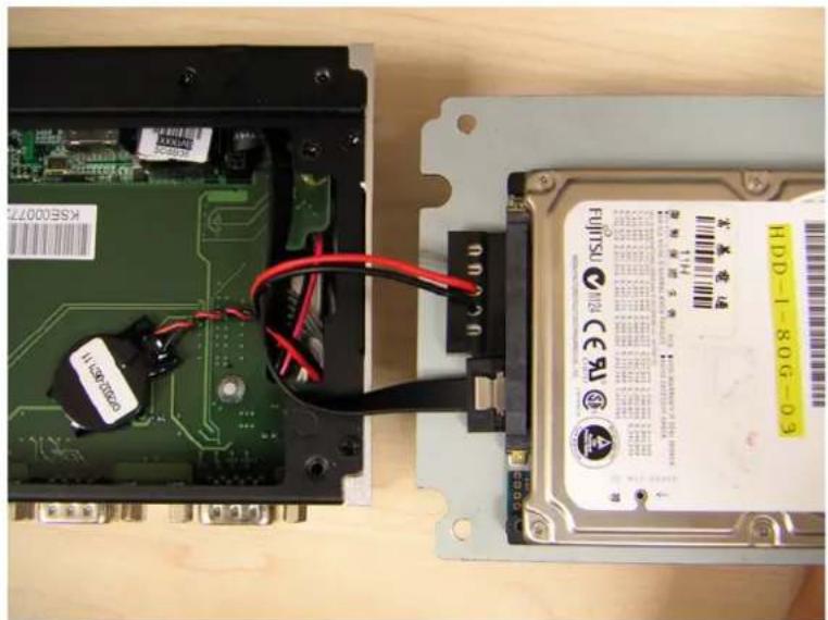
natural_image
Two electronic devices with visible internal components and wiring, one showing a circuit board and cable (no readable text or symbols)- Secure the bottom cover in its original position.
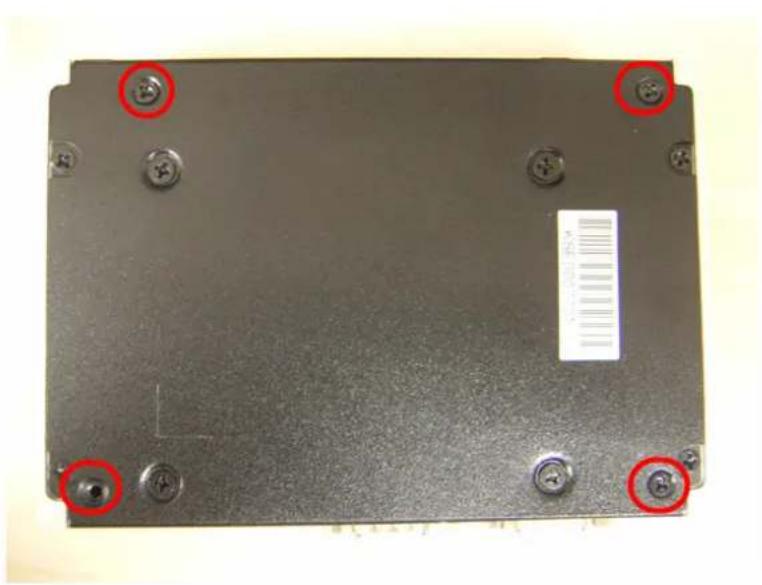
natural_image
Metallic electronic component with four mounting holes and a barcode tag (no readable text or symbols)2.7.2 mSATA HD Installation
** Below installation is for ARK-1122H & ARK-1122C ONLY, NOT for ARK-1122F. For ARK-1122F, we suggest to install by CTOS due to complex installation.
- Unscrew the bottom cover screws.
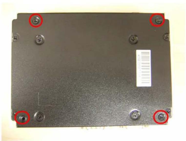
natural_image
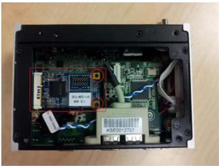
Close-up of a metallic electronic device with four mounting holes and red circular annotations highlighting features (no readable text or symbols)- Insert mSTAT HD into the slot and secure the screw to fix the mSATA HD.
- Secure the original screw.
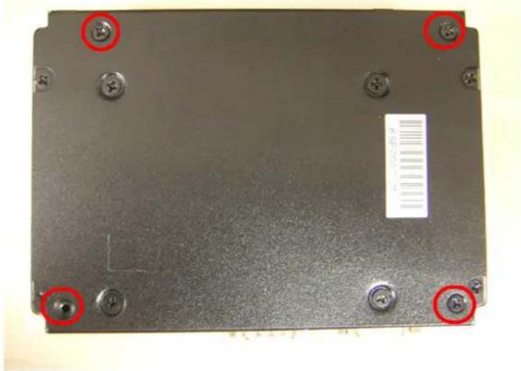
natural_image
Close-up of a metallic electronic device with four mounting holes and a barcode tag (no readable text or symbols)2.7.3 RAM Installation
- Unscrew the four screws on bottom cover. (marked with "RAM")
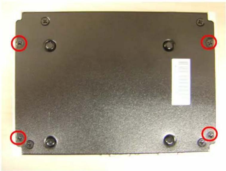
natural_image
Metallic electronic component with four mounting holes and red circular annotations highlighting features (no text or symbols)- Unscrew the four screws on the sides of ARK-1122.
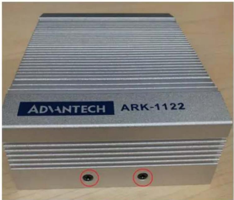
- Unscrew the four screws on the front/rear face plate of ARK-1122.
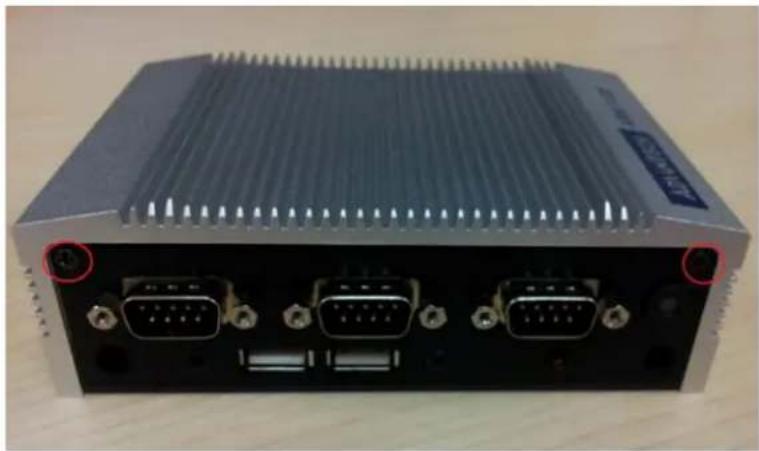
natural_image
Front view of a black industrial electronic device with three connected ports (no visible text or symbols)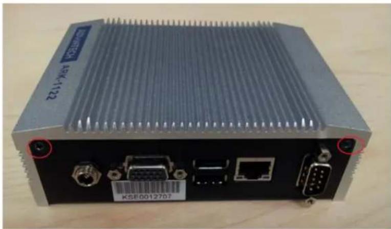
natural_image
Front view of a black industrial electronic device with heat sink, ports, and connectors (no visible text or symbols)- Remove aluminum top chassis and install RAM.
![09-2820 15 DOBA 106S SOOAM CT7 [VD] 596096-0013 Rads [VD] TRAVOCAND E M10-2260 00 AS50032733 965226000E 00](/content/2026/05/975477/images/4b404aa4140e3752e4684f88de843cb77fca0d9e7d380a9a9b1da6cae28b960b.jpg)
- Replace the aluminum top chassis and secure all screws.
Chapter 3
BIOS Settings
This chapter introduces how to set BIOS configuration data.
3.1 Introduction
AMIBIOS has been integrated into a plethora of motherboards for a couple decades. With the AMIBIOS Setup program, users can modify BIOS settings and control various system features. This chapter describes the basic navigation of the ARK-1122 BIOS setup screens.
![Aptio Setup Utility - Copyright (C) 2011 American Megatrends, Inc. Main Advanced Chipset Boot Security Save & Exit BIOS Information BIOS Vendor Core Version Compliancy Project Version Build Date and Time Total Memory Memory Frequency System Date System Time Access Level American Megatrends 4.6.5.1 0.14 x64 UEFI 2.3 ARK 1122X002 11/14/2012 09:57:10 4096 MB (DDR3) 800 MHz(DDR3) [Tue 08/05/2013] [09:37:04] Administrator Set the Date. Use Tab to switch between Data elements. +: Select Screen +: Select Item Enter: Select +/-: Change Opt. F1: General Help F2: Previous Values F3: Optimized Defaults F4: Save & Exit ESC: Exit Version 2.14.1219. Copyright (C) 2011 American Megatrends, Inc.](/content/2026/05/975477/images/a6c8bf71d1752527d7fafa01269a8b496b1a732b00dbbb2024fdb0f686e09972.jpg)
Figure 3.1 Setup program initial screen
AMI's BIOS ROM has a built-in Setup program that allows users to modify the basic system configuration. This information is stored in flash ROM so it retains the Setup information when the power is turned off.
3.2 Entering Setup
Turn on the computer and then press to enter Setup menu.
3.2.1 Main Setup
When users first enter the BIOS Setup Utility, users will enter the Main setup screen. Users can always return to the Main setup screen by selecting the Main tab. There are two Main Setup options. They are described in this section. The Main BIOS Setup screen is shown below.
![Aptio Setup Utility - Copyright (C) 2011 American Megatrends, Inc. Main Advanced Chipset Boot Security Save & Exit BIOS Information BIOS Vendor American Megatrends Core Version 4.6.5.1 0.14 x64 Compliancy UEFI 2.3 Project Version ARK 1122X002 Build Date and Time 11/14/2012 09:57:10 Total Memory 4096 MB (DDR3) Memory Frequency 800 MHz(DDR3) System Date [Tue 03/05/2013] System Time [09:37:04] Access Level Administrator Set the Date. Use Tab to switch between Data elements. +: Select Screen 11: Select Item Enter: Select +/-: Change Opt. F1: General Help F2: Previous Values F3: Optimized Defaults F4: Save & Exit ESC: Exit Version 2.14.1219. Copyright (C) 2011 American Megatrends, Inc.](/content/2026/05/975477/images/ca055fe1ec6acb185aedd5a0b6ed6010c1877f3b7e7e27e677450199362c67d6.jpg)
Figure 3.2 Main Setup Screen
The Main BIOS setup screen has two main frames. The left frame displays all the options that can be configured. Grayed-out options cannot be configured; options in blue can. The right frame displays the key legend. Above the key legend is an area reserved for a text message. When an option is selected in the left frame, it is highlighted in white. Often a text message will accompany it.
■ System Time / System Date
Use this option to change the system time and date. Highlight System Time or System Date using the
3.2.2 Advanced BIOS Features Setup
Select the Advanced tab from the ARK-1122 setup screen to enter the Advanced BIOS Setup screen. You can select any of the items in the left frame of the screen, such as CPU Configuration, to go to the sub menu for that item. You can display an Advanced BIOS Setup option by highlighting it using the
![Aptio Setup Utility - Copyright (C) 2011 American Megatrends, Inc. Main Advanced Chipset Boot Security Save & Exit Legacy OpROM Support Launch PXE OpROM [Disabled] Launch Storage OpROM [Enabled] ► Advantech Bios Update V1.3 ► ACPI Settings ► CPU Configuration ► IDE Configuration ► Intel Fast Flash Standby ► USB Configuration ► Super IO Configuration ► H/W Monitor ► AOAC Configuration ► PPM Configuration Enable or Disable Boot Option for Legacy Network Devices. +: Select Screen 1↓: Select Item Enter: Select +/-: Change Opt. F1: General Help F2: Previous Values F3: Optimized Defaults F4: Save & Exit ESC: Exit Version 2.14.1219. Copyright (C) 2011 American Megatrends, Inc.](/content/2026/05/975477/images/3b520cf5657e36017772bdf7eb3a5d32bc1cd1053fb00166fba724e7ec7c8c2f.jpg)
Figure 3.3 Advanced BIOS Features Setup Screen
3.2.2.1 ACPI Settings
![Aptio Setup Utility - Copyright (C) 2011 American Megatrends, Inc. Advanced ACPI Settings Enable ACPI Auto Configuration [Disabled] Enable Hibernation [Enabled] ACPI Sleep State [S3 (Suspend to RAM)] Lock Legacy Resources [Disabled] S3 Video Repost [Disabled] Enables or Disables BIOS ACPI Auto Configuration. +: Select Screen ↓: Select Item Enter: Select +/-: Change Opt. F1: General Help F2: Previous Values F3: Optimized Defaults F4: Save & Exit ESC: Exit Version 2.14.1219. Copyright (C) 2011 American Megatrends, Inc.](/content/2026/05/975477/images/76dd4c9df8045d5510873060a8a806113ddfe79703ada12a6d919f58211e8678.jpg)
Figure 3.4 ACPI Setting
■ Enable ACPI Auto Configuration
This item allows users to enable or disable BIOS ACPI auto configuration.
ACPI Sleep State
This item allows users to set the ACPI sleep state.
■ Lock Legacy Resources
This item allows users to lock legacy devices' resources.
S3 Video Repost
This item allows users to enable or disable VBIOS run after S3 resume.
3.2.2.2 CPU Configuration
![Aptio Setup Utility - Copyright (C) 2011 American Megatrends, Inc. Advanced CPU Configuration Processor Type Intel(R) Atom(TM) CPU EMT64 Supported Processor Speed 1600 MHz System Bus Speed 400 MHz Ratio Status 16 Actual Ratio 16 System Bus Speed 400 MHz Processor Stepping 30661 Microcode Revision 266 L1 Cache RAM 2x56 k L2 Cache RAM 2x512 k Processor Core Dual Hyper-Threading Supported Hyper-Threading [Enabled] Execute Disable Bit [Enabled] Limit CPUID Maximum [Disabled] Enabled for Windows XP and Linux (OS optimized for Hyper-Threading Technology) and Disabled for other OS (OS not optimized for Hyper-Threading Technology). +: Select Screen ↑↓: Select Item Enter: Select +/-: Change Opt. F1: General Help F2: Previous Values F3: Optimized Defaults F4: Save & Exit ESC: Exit Version 2.14.1219. Copyright (C) 2011 American Megatrends, Inc.](/content/2026/05/975477/images/77ff296418fadc4b168e8994fe03514c4bff81a0cea44502419cf948b8a6c958.jpg)
Figure 3.5 CPU Configuration Settings
Hyper-Threading
This item allows you to enable or disable Intel® Hyper Threading technology.
■ Execute Disable Bit
This item allows you to enable or disable the No-Execution page protection technology.
■ Limit CPUID Maximum
This item allows you to limit CPUID maximum value.
3.2.2.3 IDE Configuration
![Aptio Setup Utility - Copyright (C) 2011 American Megatrends, Inc. Advanced SATA Port0 Not Present SATA Port1 Not Present SATA Controller(s) [Enabled] Configure SATA as [IDE] Misc Configuration for hard disk SATA Ports (0-3) Device Names if Present and Enabled. +: Select Screen ↑↓: Select Item Enter: Select +/-: Change Opt. F1: General Help F2: Previous Values F3: Optimized Defaults F4: Save & Exit ESC: Exit Version 2.14.1219. Copyright (C) 2011 American Megatrends, Inc.](/content/2026/05/975477/images/91042eda0e59400125202b789023ecbd010b0d1211fa9c88c012bc9eb69b48c1.jpg)
Figure 3.6 IDE Configuration
■ SATA Controller
This item allows users to enable or disable the SATA controller.
3.2.2.4 Intel Fast Flash Standby
![Aptio Setup Utility - Copyright (C) 2011 American Megatrends, Inc. Advanced IFFS Support [Disabled] Enable or disable iFFS. +: Select Screen ↑↓: Select Item Enter: Select +/-: Change Opt. F1: General Help F2: Previous Values F3: Optimized Defaults F4: Save & Exit ESC: Exit Version 2.14.1219. Copyright (C) 2011 American Megatrends, Inc.](/content/2026/05/975477/images/fb44043530b1fa2b047bc2ef413c6f33a576f13c801b699bb68cf685c273f06d.jpg)
Figure 3.7 Intel Fast Flash Standby
IFFS Support
This item allows users to enable or disable IFFS support.
3.2.2.5 USB Configuration
| Aptio Setup Utility - Copyright (C) 2011 American Megatrends, Inc. Advanced | |
| USB Configuration USB Devices: 1 Drive, 1 Keyboard Legacy USB Support [Enabled] EHCI Hand-off [Disabled] USB hardware delays and time-outs: USB transfer time-out [20 sec] Device reset time-out [20 sec] Device power-up delay [Auto] | Enables Legacy USB support. AUTO option disables legacy support if no USB devices are connected. DISABLE option will keep USB devices available only for EFI applications. |
| +: Select Screen ↑↓: Select Item Enter: Select +/-: Change Opt. F1: General Help F2: Previous Values F3: Optimized Defaults F4: Save & Exit ESC: Exit | |
| Version 2.14.1219. Copyright (C) 2011 American Megatrends, Inc. | |
Figure 3.8 USB Configuration
Legacy USB Support
Enable the support for legacy USB. Auto option disables legacy support if no USB devices are connected.
EHCI Hand-Off
This is a workaround for the OS without EHCl hand-off support. The EHCl ownership change should be claimed by EHCl driver.
USB transfer time-out
Set the time-out value for Control, Bulk, and Interrupt transfers.
■ Device reset time-out
Set USB mass storage device Start Unit command time-out value.
■ Device power-up delay
Set the maximum time the device will take before it properly reports itself to the Host Controller. 'Auto' uses default value: for a Root port it is 100 ms, for a Hub port the delay is taken from Hub descriptor.
3.2.2.6 Super IO Configuration
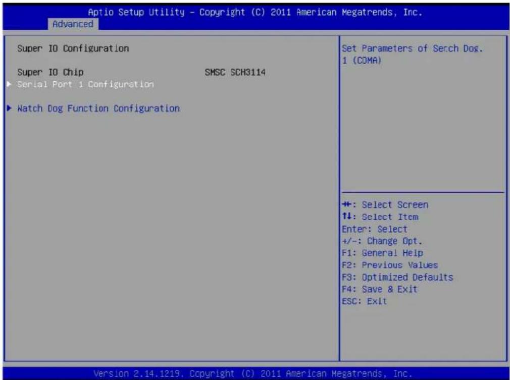
Figure 3.9 Super IO Configuration
Serial Port 1 configuration
This item allows you to select serial port1 configuration.
Serial Port 2 - 4 configuration (ARK-1122C only)
This item allows you to select serial port 2 \~ 4 configuration. Serial port3 and port4 can be set as RS-232/RS-422/RS-485. The default setting is RS-232.
- WatchDog function
This item allows you to enable WatchDog function, in minutes or seconds.
3.2.2.7 H/W Monitor
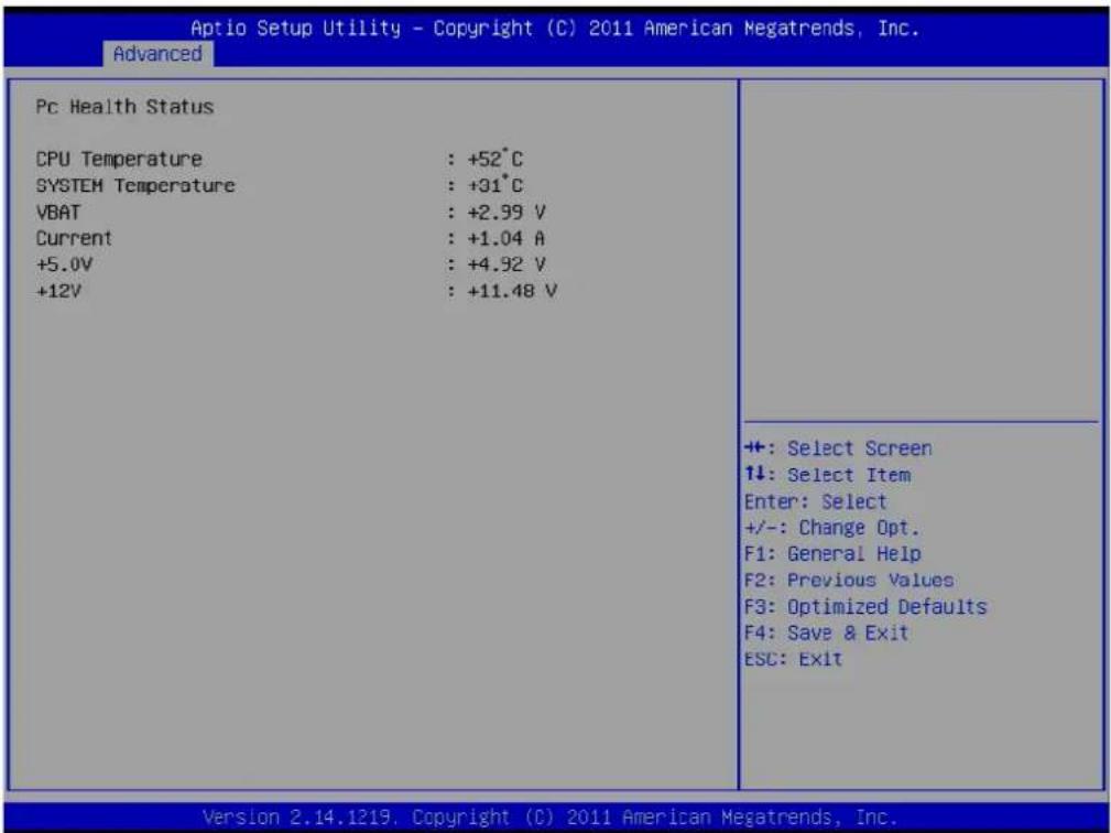
Figure 3.10 H/W Monitor
■ Temperature & Voltage show
CPU / System Temperature / VBAT / Current / +5.0 V / +12 V
3.2.2.8 AOAC Configuration
![Aptio Setup Utility - Copyright (C) 2011 American Megatrends, Inc. Advanced ADAC Configuration [Disabled] Enable/Disable AOAC Configuration +: Select Screen 1+: Select Item Enter: Select +/-: Change Opt. F1: General Help F2: Previous Values F3: Optimized Defaults F4: Save & Exit ESC: Exit Version 2.14.1219. Copyright (C) 2011 American Megatrends, Inc.](/content/2026/05/975477/images/1b32a14c98a74c6f2a757be7f1218af0d9c3e1768889759e2f62d3e6a1185949.jpg)
Figure 3.11 AOAC Configuration
AOAC Configuration
This item allows users to enable or disable AOAC Configuration.
3.2.2.9 PPM Configuration
![Aptio Setup Utility - Copyright (C) 2011 American Megatrends, Inc. Advanced PPM Configuration EIST [Enabled] CPU C state Report [Enabled] Enhanced C state [Enabled] CPU Hard C4E [Enabled] CPU C6 state [Enabled] C4 Exit Timing [Fast] C-state POPDOWN [Enabled] C-state POPUP [Enabled] Enable/Disable Intel SpeedStep +: Select Screen ↓: Select Item Enter: Select +/-: Change Opt. F1: General Help F2: Previous Values F3: Optimized Defaults F4: Save & Exit ESC: Exit Version 2.14.1219. Copyright (C) 2011 American Megatrends, Inc.](/content/2026/05/975477/images/c44ef300e2ba8ac18a0028899d4bf4071b2310a197c6fa92cc9fd6388aafbe54.jpg)
Figure 3.12 PPM Configuration
EIST
CPU runs at its default speed if disabled; CPU speed is controlled by the operating system if enabled.
■ CPU C State Report
This item allows users to enable or disable CPU C state report.
■ Enhanced C State
This item allows users to enable or disable enhanced C state.
CPU Hard C4E This item allows users to enable or disable CPU hard C4E
■ CPU C6 State
This item allows users to enable or disable CPU C6 state.
C4 Exit Timing
This item allows users to enable or disable C4 exit timing.
C State POPDOWN This item allows users to enable or disable C state popdown
C State POPUP
This item allows users to enable or disable C state popup.
3.2.3 Chipset
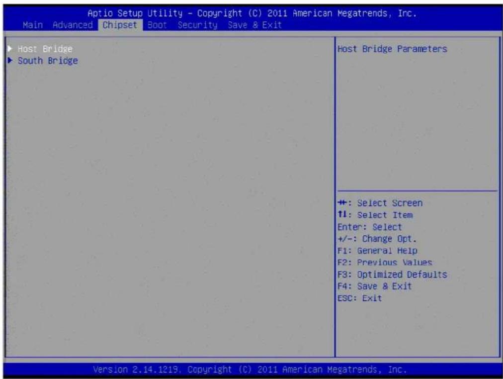
Figure 3.13 Chipset Setup
3.2.3.1 Host Bridge
![Aptio Setup Utility - Copyright (C) 2011 American Megatrends, Inc. Chipset Intel IGD Configuration Auto Disable IGD [Enabled] IGFX - Boot Type [VBIOS Default] IGD Clock Source [External Clock] Fixed Graphics Memory Size [128MB] ALS Support [Disabled] Auto disable IGD upon external GFX detected. +: Select Screen 1+: Select Item Enter: Select +/-: Change Opt. F1: General Help F2: Previous Values F3: Optimized Defaults F4: Save & Exit ESC: Exit Version 2.14.1219. Copyright (C) 2011 American Megatrends, Inc.](/content/2026/05/975477/images/a050ffe1dad8fe9d8b43d9d71356c5bf98131f3a1e1380319474d7e459baeb0a.jpg)
Figure 3.14 Chipset Setup
■ Auto Disable IGD
This item allows user to enable/disable auto disable IGD
IGFX - Boot Type
This item allows user to select IGFX boot type.
IGD - Clock Source
This item allows user to select IGD-clock source
ALS Support
This item allows user to enable/disable ALS support
3.2.3.2 South Bridge
![Aptio Setup Utility - Copyright (C) 2011 American Megatrends, Inc. Chipset ► TPT Devices ► PCI Express Root Port 0 ► PCI Express Root Port 1 ► PCI Express Root Port 2 DMI Link ASPM Control [Enabled] High Precision Event Timer Configuration High Precision Timer [Enabled] SLP_S4 Assertion Width [1-2 Seconds] Restore AC Power Loss [Last State] Enable/Disable Intel(R) IO Controller Hub (TPT) devices +: Select Screen ↑↓: Select Item Enter: Select +/-: Change Opt. F1: General Help F2: Previous Values F3: Optimized Defaults F4: Save & Exit ESC: Exit Version 2.14.1219. Copyright (C) 2011 American Megatrends, Inc.](/content/2026/05/975477/images/2a7a50dbaaaea653a0067dd5a711d82522c07dca6508dddab26e8c3cc5dcf472.jpg)
Figure 3.15 Chipset Setup
■ DMI Link ASPM Control
This item allows users to enable/disable DMI link ASPM control.
■ High Precision Timer
This item allows users to enable/disable high precision timer.
■ SLP_S4 Assertion Width
This item allows user to select the SLP_S4 assertion width.
■ Restore AC Power Loss
This item allows users to select restore AC power loss.
3.2.4 Boot
![Aptio Setup Utility - Copyright (C) 2011 American Megatrends, Inc. Main Advanced Chipset Boot Security Save & Exit Boot Configuration Setup Prompt Timeout Bootup NumLock State Quiet Boot CSM16 Module Version Option ROM Messages Interrupt 19 Capture CSM Support Boot Option Priorities Boot Option #1 Number of seconds to wait for setup activation key. 65535(0xFFFF) means indefinite waiting. [Disabled] 07.68 [Force BIOS] [Enabled] [Enabled] [UEFI: Built-in EFI...] +: Select Screen 11: Select Item Enter: Select +/-: Change Opt. F1: General Help F2: Previous Values F3: Optimized Defaults F4: Save & Exit ESC: Exit Version 2.14.1219. Copyright (C) 2011 American Megatrends, Inc.](/content/2026/05/975477/images/5a485450ab7c54926d77d478debc7cc5a343d0285c9b3a13db4a642fe99e34d6.jpg)
Figure 3.16 Boot Setup
Setup Prompt Timeout
This item allows users to select the number of seconds to wait for setup activation key.
■ Bootup NumLock State
Select the Power-on state for Numlock.
Quiet Boot
If this option is set to Disabled, the BIOS displays normal POST messages. If Enabled, an OEM Logo is shown instead of POST messages.
Option ROM Message
Set display mode for option ROM.
■ Interrupt 19 Capture
This item allows option ROMs to trap interrupt 19.
CSM Support
This item allows users to enable/disable CSM support.
3.2.5 Security Settings
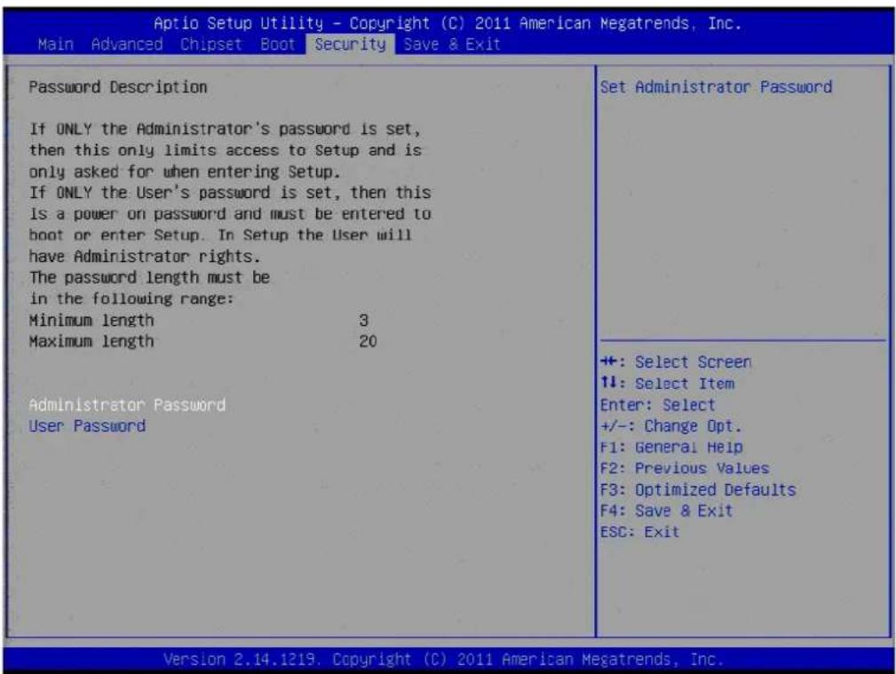
Figure 3.17 Security Setup
Select Security Setup from the ARK-1122 Setup main BIOS setup menu. All Security Setup options, such as password protection and virus protection are described in this section. To access the sub menu for the following items, select the item and press
Administrator Password
This item allows user to set up password for protection.
3.2.6 Save & Exit
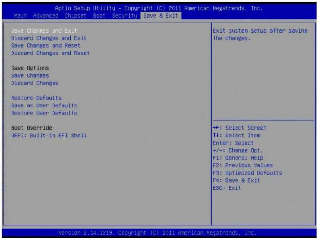
Figure 3.18 Save & Exit Setup
■ Save Changes and Exit
When users have completed system configuration, select this option to save changes, exit BIOS setup menu and reboot the computer if necessary to take effect all system configuration parameters.
■ Discard Changes and Exit
Select this option to quit Setup without making any permanent changes to the system configuration.
■ Save Changes and Reset
When users have completed system configuration, select this option to save changes, exit BIOS setup menu and reboot the computer to take effect all system configuration parameters.
■ Discard Changes and Reset
Select this option to quit Setup without making any permanent changes to the system configuration and reboot the computer.
■ Save Changes
When users have completed system configuration, select this option to save changes without exit BIOS setup menu.
■ Discard Changes
Select this option to discard any current changes and load previous system configuration.
Restore Defaults
The ARK-1122 automatically configures all setup items to optimal settings when users select this option. Optimal Defaults are designed for maximum system performance, but may not work best for all computer applications. In particular, do not use the Optimal Defaults if the user's computer is experiencing system configuration problems.
■ Save User Defaults
When users have completed system configuration, select this option to save changes as user defaults without exit BIOS setup menu.
The users can select this option to restore user defaults.
Appendix A
WDT & GPIO Sample Code
A.1 Watchdog Timer Sample Code
Watchdog function:
;The SCH3114 Runtime base I/O address is A00h
;Setting WatchDog time value location at offset 66h
;If set value "0", it is mean disable WatchDog function.
Superio_GPIO_Port = A00h

mov dx,Superio_GPIO_Port + 66h

mov al,00h

out dx,al

.model small

.486p

.stack 256

.data

SCH3114_IO EQU A00h

.code

org 100h

.STARTup

;================

;47H

;enable WDT function bit [0]=0Ch

;================

mov dx,SCH3114_IO + 47h

mov al,0Ch

out dx,al

;================

;65H

;bit [1:0]=Reserved

;bit [6:2]Reserve=00000

;bit [7] WDT time-out Value Units Select

;Minutes=0 (default) Seconds=1

;================

mov dx,SCH3114_IO + 65h ;

mov al,080h

out dx,al

;================

;66H

;WDT timer time-out value

;bit[7:0]=0~255

;================

mov dx,SCH3114_IO + 66h

mov al,01h

out dx,al

;================

;bit[0] status bit R/W

;WD timeout occurred =1
;WD timer counting = 0
mov dx,SCH3114_IO + 68h
mov al,01h
out dx, al
.exit
END
ADVANTECH
Enabling an Intelligent Planet
www.advantech.com
Please verify specifications before quoting. This guide is intended for reference purposes only.
All product specifications are subject to change without notice.
No part of this publication may be reproduced in any form or by any means, electronic, photocopying, recording or otherwise, without prior written permission of the publisher.
All brand and product names are trademarks or registered trademarks of their respective companies.
© Advantech Co., Ltd. 2014
- ARK-1122
- Fanless Embedded Box PC
- Attention!
- Copyright
- Acknowledgements
- Product Warranty (2 years)
- Declaration of Conformity
- FCC Class A
- Technical Support and Assistance
- Warnings, Cautions and Notes
- Safety Instructions
- Packing list
- Ordering Information
- Optional Accessories
- Contents
- Chapter 1 General Introduction ......1
- Chapter 2 Hardware installation ....7
- Chapter 3 BIOS Settings 29
- Appendix A WDT & GPIO Sample Code .....49
- Chapter 1
- General Introduction
- Introduction
- Features
- Key features
- Specifications
- General
- Display
- Ethernet
- Power Consumption
- Power Requirement
- Environmental Specifications
- Mechanical Specifications
- ARK-1122H Dimensions
- ARK-1122C Dimensions
- ARK-1122F Dimensions
- Chapter 2
- Introduction
- Jumpers
- Jumper list
- Jumper Settings
- Jumper Description
- ARK-1122 I/O Indication
- ARK-1122C
- ARK-1122H External I/O Connectors
- Power ON/OFF Button
- Power Input Connector
- Ethernet Connector (LAN)
- VGA Connector
- USB Connectors
- Audio Connector
- COM Connector
- HDMI Connector
- ARK-1122C External I/O Connectors
- Power ON/OFF Button
- Power Input Connector
- Ethernet Connector (LAN)
- VGA Connector
- USB Connectors
- Audio Connector
- COM Connector
- ARK-1122F External I/O Connectors
- Power ON/OFF Button
- Power Input Connector
- Ethernet Connector (LAN)
- VGA Connector
- USB Connectors
- Audio Connector
- COM Connector
- HDMI Connector
- SIM Card Holder
- Peripheral Installation
- HDD Installation (ARK-1122H only)
- mSATA HD Installation
- RAM Installation
- Chapter 3
- BIOS Settings
- Introduction
- Entering Setup
- Main Setup
- ■ System Time / System Date
- Advanced BIOS Features Setup
- ACPI Settings
- CPU Configuration
- Hyper-Threading
- ■ Execute Disable Bit
- ■ Limit CPUID Maximum
- IDE Configuration
- ■ SATA Controller
- Intel Fast Flash Standby
- IFFS Support
- USB Configuration
- Legacy USB Support
- EHCI Hand-Off
- USB transfer time-out
- ■ Device reset time-out
- ■ Device power-up delay
- Super IO Configuration
- H/W Monitor
- ■ Temperature & Voltage show
- AOAC Configuration
- AOAC Configuration
- PPM Configuration
- Chipset
- Host Bridge
- South Bridge
- Boot
- Setup Prompt Timeout
- ■ Bootup NumLock State
- Quiet Boot
- Option ROM Message
- ■ Interrupt 19 Capture
- CSM Support
- Security Settings
- Administrator Password
- Save & Exit
- ■ Save Changes and Exit
- ■ Discard Changes and Exit
- ■ Save Changes and Reset
- ■ Discard Changes and Reset
- ■ Save Changes
- ■ Discard Changes
- Restore Defaults
- ■ Save User Defaults
- Appendix A
- A.1 Watchdog Timer Sample Code
- ADVANTECH
- www.advantech.com
Brand : Advantech
Model : ARK-1122
Category : Desktop computer