
PPC-4211W - Desktop computer Advantech - Free user manual and instructions
Find the device manual for free PPC-4211W Advantech in PDF.


| Product Type | Industrial Panel PC |
| Display Size | 21.5-inch |
| Resolution | 1920 x 1080 (Full HD) |
| Processor | Intel Core i5-1145G7 (up to 4.4 GHz) |
| Memory | 8 GB DDR4 (expandable up to 32 GB) |
| Storage | 256 GB M.2 SSD |
| Operating System | Windows 10 IoT Enterprise |
| Touchscreen | Projected Capacitive (10-point touch) |
| Input Ports | 2x USB 3.2, 2x USB 2.0, 1x RS-232, 1x RS-422/485 |
| Display Ports | 1x HDMI, 1x DisplayPort |
| Networking | 2x Gigabit Ethernet, Wi-Fi 6, Bluetooth 5.0 |
| Audio | Built-in speakers, microphone, headphone jack |
| Power Supply | 100-240V AC, 50-60Hz, 120W adapter |
| Power Consumption | Typical 60W, Max 90W |
| Dimensions (W x H x D) | 534 x 348 x 50 mm (21 x 13.7 x 2 in) |
| Weight | 6.5 kg (14.3 lbs) |
| Operating Temperature | 0°C to 50°C (32°F to 122°F) |
| Ingress Protection | Front panel IP65 (dust and water jets) |
| Mounting | Panel mount, VESA 100x100 |
| Certifications | CE, FCC, UL |
| Warranty | 3 years limited |
Frequently Asked Questions - PPC-4211W Advantech
User questions about PPC-4211W Advantech
0 question about this device. Answer the ones you know or ask your own.
Ask a new question about this device
Download the instructions for your Desktop computer in PDF format for free! Find your manual PPC-4211W - Advantech and take your electronic device back in hand. On this page are published all the documents necessary for the use of your device. PPC-4211W by Advantech.
USER MANUAL PPC-4211W Advantech
natural_image
Illustration of three kitchen appliances in green outline style (no text or symbols)PPC-4211W
Intel® Core i processor based microcomputer, with 21.5" color TFT LCD display
Copyright
The documentation and the software included with this product are copyrighted 2014 by Advantech Co., Ltd. All rights are reserved. Advantech Co., Ltd. reserves the right to make improvements in the products described in this manual at any time without notice. No part of this manual may be reproduced, copied, translated or transmitted in any form or by any means without the prior written permission of Advantech Co., Ltd. Information provided in this manual is intended to be accurate and reliable. However, Advantech Co., Ltd. assumes no responsibility for its use, nor for any infringements of the rights of third parties, which may result from its use.
Acknowledgements
Intel and Pentium are trademarks of Intel Corporation.
Microsoft Windows is registered trademark of Microsoft Corp.
All other product names or trademarks are properties of their respective owners.
Product Warranty (2 years)
Advantech warrants to you, the original purchaser, that each of its products will be free from defects in materials and workmanship for two years from the date of purchase.
This warranty does not apply to any products which have been repaired or altered by persons other than repair personnel authorized by Advantech, or which have been subject to misuse, abuse, accident or improper installation. Advantech assumes no liability under the terms of this warranty as a consequence of such events.
Because of Advantech's high quality-control standards and rigorous testing, most of our customers never need to use our repair service. If an Advantech product is defective, it will be repaired or replaced at no charge during the warranty period. For out-of-warranty repairs, you will be billed according to the cost of replacement materials, service time and freight. Please consult your dealer for more details.
If you think you have a defective product, follow these steps:
-
Collect all the information about the problem encountered. (For example, CPU speed, Advantech products used, other hardware and software used, etc.) Note anything abnormal and list any onscreen messages you get when the problem occurs.
-
Call your dealer and describe the problem. Please have your manual, product, and any helpful information readily available.
-
If your product is diagnosed as defective, obtain an RMA (return merchandise authorization) number from your dealer. This allows us to process your return more quickly.
-
Carefully pack the defective product, a fully-completed Repair and Replacement Order Card and a photocopy proof of purchase date (such as your sales receipt) in a shippable container. A product returned without proof of the purchase date is not eligible for warranty service.
-
Write the RMA number visibly on the outside of the package and ship it prepaid to your dealer.
Part No. 200K421110 Edition 1
Printed in China May 2014
Declaration of Conformity
CE
This product has passed the CE test for environmental specifications when shielded cables are used for external wiring. We recommend the use of shielded cables. This kind of cable is available from Advantech. Please contact your local supplier for ordering information.
CE
This product has passed the CE test for environmental specifications. Test conditions for passing included the equipment being operated within an industrial enclosure. In order to protect the product from being damaged by ESD (Electrostatic Discharge) and EMI leakage, we strongly recommend the use of CE-compliant industrial enclosure products.
FCC Class B
Note: This equipment has been tested and found to comply with the limits for a Class B digital device, pursuant to part 15 of the FCC Rules. These limits are designed to provide reasonable protection against harmful interference in a residential installation. This equipment generates, uses and can radiate radio frequency energy and, if not installed and used in accordance with the instructions, may cause harmful interference to radio communications. However, there is no guarantee that interference will not occur in a particular installation. If this equipment does cause harmful interference to radio or television reception, which can be determined by turning the equipment off and on, the user is encouraged to try to correct the interference by one or more of the following measures:
■ Reorient or relocate the receiving antenna.
■ Increase the separation between the equipment and receiver.
■ Connect the equipment into an outlet on a circuit different from that to which the receiver is connected.
Consult the dealer or an experienced radio/TV technician for help.
Technical Support and Assistance
- Visit the Advantech web site at http://support.advantech.com where you can find the latest information about the product.
- Contact your distributor, sales representative, or Advantech's customer service center for technical support if you need additional assistance. Please have the following information ready before you call:
– Product name and serial number
– Description of your peripheral attachments
– Description of your software (operating system, version, application software, etc.)
– A complete description of the problem
– The exact wording of any error messages
Safety Instructions
- Read these safety instructions carefully.
- Keep this User Manual for later reference.
- Disconnect this equipment from any AC outlet before cleaning. Use a damp cloth. Do not use liquid or spray detergents for cleaning.
- For plug-in equipment, the power outlet socket must be located near the equipment and must be easily accessible.
- Keep this equipment away from humidity.
- Put this equipment on a reliable surface during installation. Dropping it or letting it fall may cause damage.
- The openings on the enclosure are for air convection. Protect the equipment from overheating. DO NOT COVER THE OPENINGS.
- Make sure the voltage of the power source is correct before connecting the equipment to the power outlet.
- Position the power cord so that people cannot step on it. Do not place anything over the power cord.
- All cautions and warnings on the equipment should be noted.
- If the equipment is not used for a long time, disconnect it from the power source to avoid damage by transient overvoltage.
- Never pour any liquid into an opening. This may cause fire or electrical shock.
- Never open the equipment. For safety reasons, the equipment should be opened only by qualified service personnel.
- If one of the following situations arises, get the equipment checked by service personnel:
■ The power cord or plug is damaged.
- Liquid has penetrated into the equipment.
■ The equipment has been exposed to moisture.
The equipment does not work well, or you cannot get it to work according to the user's manual.
■ The equipment has been dropped and damaged.
■ The equipment has obvious signs of breakage.
-
DO NOT LEAVE THIS EQUIPMENT IN AN ENVIRONMENT WHERE THE STORAGE TEMPERATURE MAY GO BELOW -20^ C ( -4^ F) OR ABOVE 60^ C ( 140^ F). THIS COULD DAMAGE THE EQUIPMENT. THE EQUIPMENT SHOULD BE IN A CONTROLLED ENVIRONMENT.
-
CAUTION: DANGER OF EXPLOSION IF BATTERY IS INCORRECTLY REPLACED. REPLACE ONLY WITH THE SAME OR EQUIVALENT TYPE RECOMMENDED BY THE MANUFACTURER, DISCARD USED BATTERIES ACCORDING TO THE MANUFACTURER'S INSTRUCTIONS.
The sound pressure level at the operator's position according to IEC 704-1:1982 is no more than 70 dB (A).
DISCLAIMER: This set of instructions is given according to IEC 704-1. Advantech disclaims all responsibility for the accuracy of any statements contained herein.
Safety Precaution - Static Electricity
Follow these simple precautions to protect yourself from harm and the products from damage.
To avoid electrical shock, always disconnect the power from your PC chassis before you work on it. Don't touch any components on the CPU card or other cards while the PC is on.
■ Disconnect power before making any configuration changes. The sudden rush of power as you connect a jumper or install a card may damage sensitive electronic components.
Battery Information
Batteries, battery packs and accumulators should not be disposed of as unsorted household waste. Please use the public collection system to return, recycle, or treat them in compliance with the local regulations.

Contents
Chapter 1 General Information ....1
1.1 Introduction 2
1.2 Specifications ...... 2
1.2.1 General Specification.... 2
1.2.2 Power Specifications.... 3
1.2.3 Touchscreen Specifications 3
1.2.4 Environment Specifications.... 3
1.2.5 Certification Specifications.... 3
1.2.6 IP 3
1.3 Dimensions 4
Figure 1.1 PPC-4211W dimensions .... 4
Chapter 2 System Installation & Setup ....5
2.1 Quick Start Guide....6
Figure 2.1 Front panel 6
Figure 2.2 Side view 6
Figure 2.3 Location of I/O interfaces....7
Figure 2.4 PCI/PCIe expansion slot....7
Figure 2.5 Grounding screw 7
2.2 Installation Procedures....8
2.2.1 Connecting the Power Cable 8
Figure 2.6 Connecting the power cable 8
2.2.2 Connecting the Keyboard and Mouse....8
2.2.3 Power ON 8
2.3 Install Memory Card 9
Figure 2.7 9
Figure 2.8 9
Figure 2.9 9
Figure 2.10....9
Figure 2.11....9
Figure 2.12....9
2.4 Installing the HDD 10
Figure 2.13.... 10
Figure 2.14.... 10
Figure 2.15.... 10
Figure 2.16....10
Figure 2.17....10
Figure 2.18.... 10
2.5 Installing Mini SATA 11
Figure 2.19....11
Figure 2.20....11
2.6 Installing Wireless LAN Card 12
Figure 2.21....12
Figure 2.22....12
Figure 2.23....12
Figure 2.24....12
Figure 2.25....13
2.7 Installing the Riser Card.... 14
Figure 2.26....14
Figure 2.27....14
Figure 2.28....14
Figure 2.29....14
2.8 AT/ATX Function Switch 14
Figure 2.30ATX mode 14
Figure 2.31AT mode.... 14
2.9 Grounding Installation 15
Figure 2.32 ...... 15
Figure 2.33 15
Figure 2.34 15
Figure 2.35 15
2.10 Hook Installation 16
Figure 2.36Hook Installation.... 16
2.11 Solo Quick Installation 17
Chapter 3 Jumper Configuration ...... 19
3.1 Jumper & Connectors ...... 20
Figure 3.1 PCM-8209 front view.... 20
3.2 External COM Port Pin Definition.... 22
Figure 3.2 COM ports 22
Chapter 4 Software Configuration ...... 25
4.1 Install Divers 26
4.2 BIOS Setup 26
4.2.1 Enter BIOS.... 26
4.2.2 Display Brightness Adjustment 27
4.2.3 COM5 Mode Selection (RS422/485) 28
4.2.4 Wake Up by LAN 29
4.2.5 RAID Installation 32
Chapter 1
General Information
This chapter gives background information on the PPC-4211W panel PC.
Sections include:
Introduction
Specifications
Dimensions
1.1 Introduction
The PPC-4211W is a new generation Panel PC with WXGA (1920 x 1080) screen. The system is equipped with a high performance Intel Core i CPU and with a high efficiency fanless thermal design the heat is easily dissipated. This gives HMI a big step forward in consolidating performance and reliability in one system. Besides, with multiple I/O ports (five COM, five USB and two Gigabit ethernet) its easier to connect to devices and be integrated into machine building industry. In addition, PCIe/PCI expansion allows users to add-on field bus or proprietary cards making more applications possible. Last but not least, the multi-touch screen makes the HMI more intuitive, and brings you the best operating experience.
1.2 Specifications
1.2.1 General Specification
| Product PPC-4211W | |||
| LCD Specification 21.5" LCD | |||
| Display Type 21.5" TFT LCD (LED backlight) | |||
| Max. Resolution 1920 x 1080 | |||
| Color 16.7M | |||
| Pixel Pitch 248.25 (per one triad) x 248.25 um | |||
| Viewing Angle 178 (left), 178 (right), 178 (top), 178 (bottom) (Typ.) | |||
| Brightness | 300 cd/m2 (Typ.) | ||
| Contrast 5000 (Typ.) | |||
| Backlight Lifecycle 50,000 hours | |||
| Weight | 7.9 Kg (17.43 lb) | ||
| Dimensions | 558.4 x 349.8 x 63.8 (mm)(21.98" x 13.77" x 2.51") | ||
| CPU | Model | Frequency | Cache |
| i5 - 4300U | 2.90GHz | 3M | |
| Celeron - 2980U | 1.60GHz | 2M | |
| Memory | One 204 pin slot, up to 8G DDR3L | ||
| Storage | Support two 2.5" SATA HDD | ||
| Network(LAN1, LAN2) | 2 x Gigabit Ethernet ports | ||
| I/O Ports | 4 x COM-RS232 Ports, 1 x RS-422/485 Port, 4 x USB 3.0, 1 x USB 2.0 | ||
| 2 x Gigabit Ethernet ports | |||
| 1 x VGA, 1 x DP | |||
| 1 x Line-out port,1 x Mic-in port, 2 x 1 W speaker (built-in) | |||
| 1 x Phoenix power port, 1 x Power switch | |||
| Expansion Slot | 1 x PCIe x4 (standard) | ||
| 1 x PCI (in the accessory box) | |||
| Additional Expansion Slot | 1 x Mini PCIe slot and 1 x mSATA card slot | ||
| System | Win 7 / Win 8 / Win 8.1 / Linux | ||
1.2.2 Power Specifications
| Power | i7: 71 W (test system: Windows7 64bit)i5: 66 W (test system: Windows7 64bit)Celeron: 58 W (test system: Windows7 64bit) |
| Output Voltage | 12-32 V_DC , 8~3 A |
Note! The above test conditions are detailed in Note 1.

1.2.3 Touchscreen Specifications
| Type | 5-point projected capacitive touchscreen (multi-touch function is only supported in Win 7/WES7P/Win 8/Win 8.1 OS) |
| Light Transmission 88%+/-5% | |
| Controller USB interface | |
1.2.4 Environment Specifications
| Operation Temperature 0 ~ 50°C (32 ~ 122°F) |
| Storage Temperature -20 ~ 60°C (-4 ~ 140°F) |
| Relative Temperature 10 ~ 95% @ 40°C (non-condensing) |
| Shock 10 G peak acceleration (11 msec duration) |
| Vibration 5 ~ 500 Hz 1 G RMS |
1.2.5 Certification Specifications
| EMC | BSMI, CE, FCC Class B |
| Safety | CB, CCC, UL |
1.2.6 IP
| Front Panel IP Grade | IP65 |
Note 1:
PPC-4211W's power test conditions are as follows:
| Test Software | Test Configuration | Test System |
| Burn-in 7.0 | Memory: Transcend DDR3L 1600 SODIMM 8 GB x 1HDD: Seageat 500G 2.5"x 2IO: COM Port RS232 loopback x4, USB3.0 device x4,USB mouse x1 | Win7(64bit) |
1.3 Dimensions
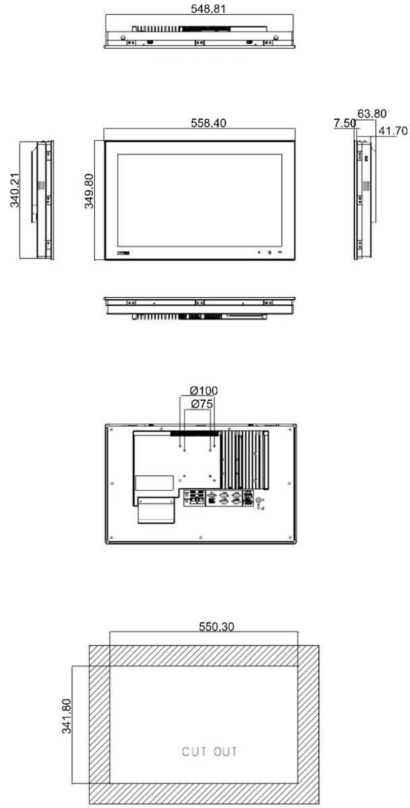
Figure 1.1 PPC-4211W dimensions
Note! Supports VESA 100 x 100mm & 75 x 75mm; please use M4 screw, 6 mm depth (maximum). Use suitable mounting apparatus to avoid risk of injury.
Chapter 2
System Installation & Setup
Sections include:
■ Quick Installation Guide
■ Installation Procedures
Installing Memory
Installing HDD
Installing Mini SATA
■ Installing Wireless LAN
■ Installing Expansion Card
■ AT/ATX Function Switch
■ Grounding Installation
Hook Installation
■ Independent Quick Installation
2.1 Quick Start Guide
Before you start to set up the panel PC, take a moment to become familiar with the locations and purposes of the controls, drives, connectors and ports, which are illustrated in the figures below.
When you place the panel PC upright on the desktop, its front panel appears as shown in Figure 2.1.
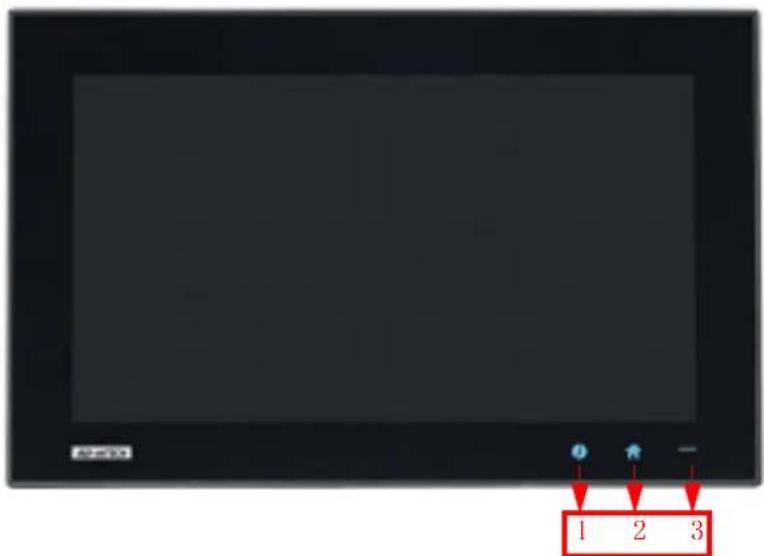
Figure 2.1 Front panel
- I Key
- Home Key
- Power status indicator, off (S5): orange, on (S0): blue
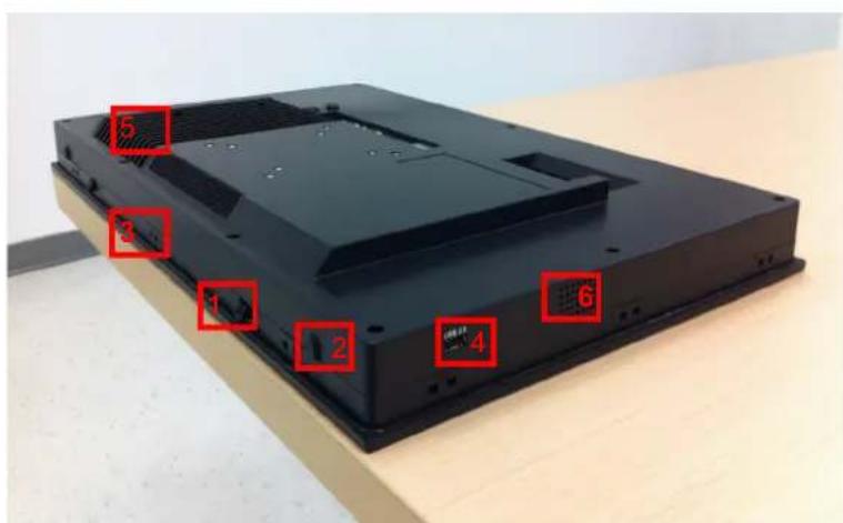
Figure 2.2 Side view
- Quick installation clip (two)
- Antenna hole (two)
- Panel Mount Bracket holes (twelve)
- Side USB 2.0 interface
- CPU cooler
- Speaker (two)
I/O interfaces:
natural_image
Back view of a computer chassis showing internal components and a labeled connection point (A), with no readable text or symbols beyond the label.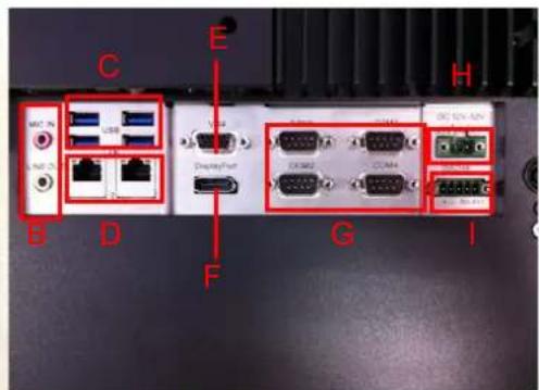
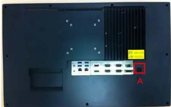
Figure 2.3 Location of I/O interfaces
A: Power button
B: Line out/Mic in
C: 4 × USB 3.0
D: 2 x Giga Ethernet
E: VGA
F: DP
G: 4 × COM RS232
H: DC power(12-32 V)
I: 1 x COM RS422/485
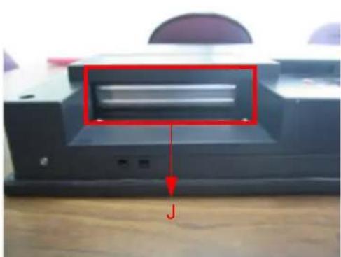
J: PCI/PCIE x4 Expansion slot (refer to Fig 2.4)
K: Grounding screw (refer to Fig 2.5)
natural_image
Close-up of a black electronic device with a red annotation pointing to a component, labeled 'J' (no readable text or symbols beyond the label)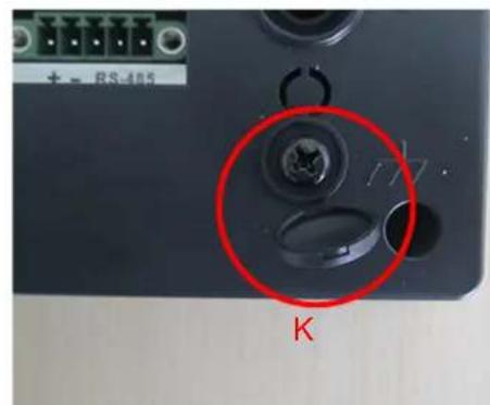
Figure 2.4 PCI/PCIe expansion slot Figure 2.5 Grounding screw
2.2 Installation Procedures
2.2.1 Connecting the Power Cable
The panel PC has DC power socket (12-32 V). When connecting the power cable, please hold the plug end. Please follow the procedures below:
- Connect the female end of the power cable to panel PC's DC socket.
- Connect the male end of the power cable to power outlet.
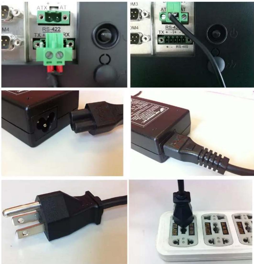
Figure 2.6 Connecting the power cable
2.2.2 Connecting the Keyboard and Mouse
Connect the keyboard and mouse to panel PC's I/O interfaces.
2.2.3 Power ON
The power button is located in the right bottom side of the panel PC.
Note!Power cable and adapter are optional.

2.3 Install Memory Card
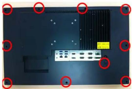
- Loosen the screws as indicated in the red circle. (See Fig 2.7)
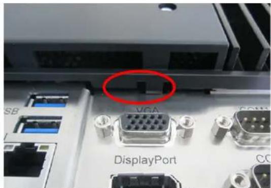
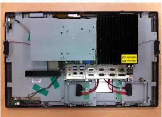
- Press the red areas to pull out the card holder (See Fig 2.8 \~ 2.10) and open the rear cover.
natural_image
Top-down view of a computer monitor chassis with visible ports and connectors, marked by red circles (no text or symbols)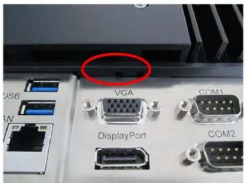
natural_image
Close-up of electronic equipment ports including VGA, DisplayPort, and COM1/2 connectors (no readable text or symbols beyond labels)Figure 2.7 Figure 2.8
natural_image
Interior view of a laptop chassis showing exposed circuit board, RAM slots, and wiring (no text or symbols visible)Figure 2.9 Figure 2.10
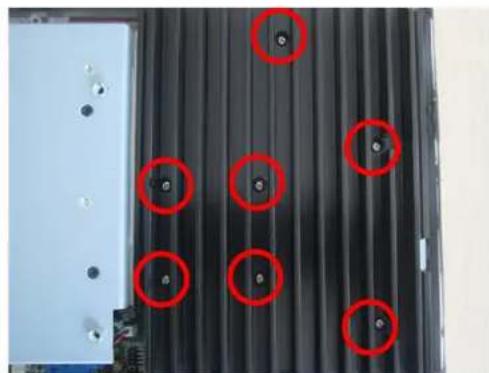
- Remove the yellow warning tag first. Then remove the screws as indicated in the red circle. (See Fig 2.11), and take out the CPU heatsink.
Note! Take out the black and gray thermal grease from the accessory box (as indicated in Figure 2.12). Attach the CPU heatsink after the grease is applied.
natural_image
Close-up of a black corrugated metal panel with red circular annotations highlighting specific features (no text or symbols present)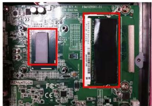
natural_image
Close-up of a green printed circuit board with two red rectangular highlights highlighting internal components (no readable text or symbols)Figure 2.11 Figure 2.12
Note!CPU cooler pad surface is isolated by anodization treatment to avoid static electricity (CPU contact side excluded).

2.4 Installing the HDD
-
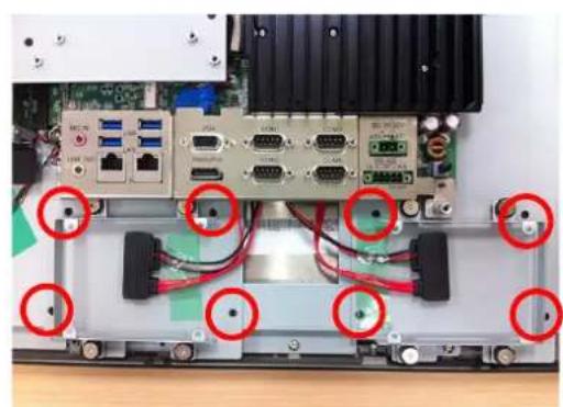
Follow the procedures in Section 2.3 to open the rear cover and remove the screws as indicated in the red circles in Fig 2.13.
-
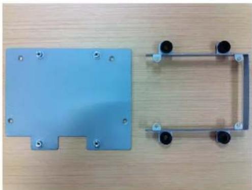
Remove the HDD bracket from the strength-plate. (See Fig 2.14 and Fig 2.15)
-
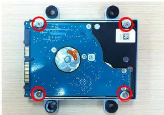
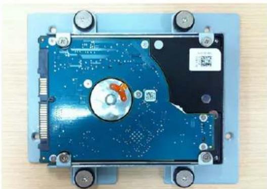
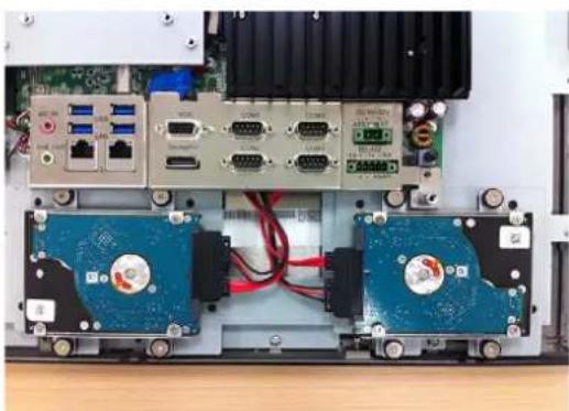
Install the HDD (see Fig 2.16 and Fig 2.17), and take out the 4 screws from the accessory box to fix the HDD and then fix the strength-plate (8 screws will be needed if using two HDDs).
-
Lock the HDD bracket, and connect the HDD cable to the mainboard. (See Fig 2.18)
natural_image
Internal view of an electronic device with multiple ports and connectors, highlighted by red circles (no visible text or symbols)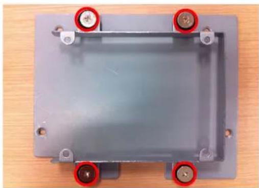
natural_image
Metal enclosure with four mounting holes and red circular markers on top (no text or symbols visible)Figure 2.13 Figure 2.14
natural_image
Two blue plastic electronic components with mounting holes and metal brackets on a wooden surface (no text or symbols visible)Figure 2.15
natural_image
Top-down view of a blue internal hard disk drive head with mounting holes and red circular annotations (no readable text or symbols)Figure 2.16
natural_image
Top-down view of a blue hard disk drive with visible circuitry and mounting holes (no text or symbols)Figure 2.17 Figure 2.18
natural_image
Interior view of an electronic device showing two blue hard drives mounted on a circuit board with multiple ports and connectors (no visible text or symbols)2.5 Installing Mini SATA
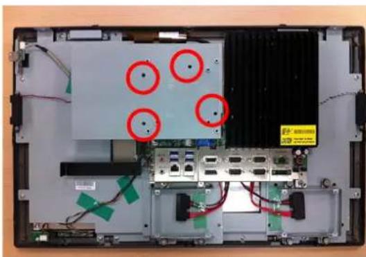
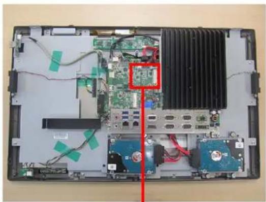
- Follow the procedures in Section 2.3 to remove the rear cover and strength-plate. (See Fig 2.19)
- Plug the MiniSATA into the mainboard interface, and remove the 2 M2.5x4 screws from the accessory box to fix it (See Fig 2.20).
- Return the rear cover and strength-plate.
natural_image
Interior view of a laptop computer showing internal components and wiring (no visible text or symbols)Figure 2.19
natural_image
Interior view of a computer motherboard showing CPU socket, drive bays, and heatsink (no text or symbols visible)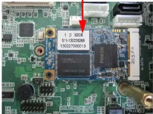
Figure 2.20
2.6 Installing Wireless LAN Card
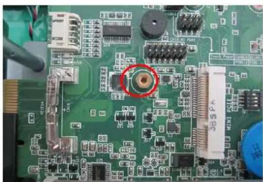
- Follow the procedures in Section 2.3 to open the rear cover and strength-plate. The wireless LAN card can be installed to the locations as indicated in Fig 2.21 and 2.22; for the wireless short card, you need to take out one hexagonal screw from the accessory box to fix it.
natural_image
Close-up of a green printed circuit board with electronic components and a red circular highlight (no readable text or symbols)Figure 2.21
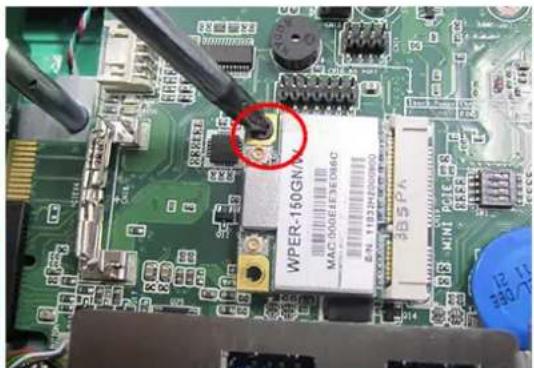
Figure 2.22
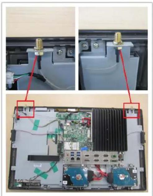
- Connect the wireless LAN card module cable to the antenna bracket, please note the installation direction of cable end and screws/cushions. (See Fig 2.23)
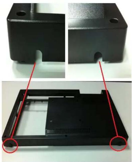
- Remove the two plugs on the left and right sides of the rear cover. (See Fig 2.24)
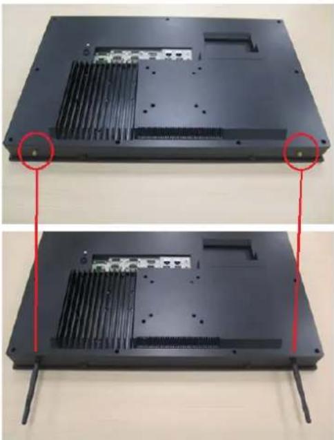
- Return the rear cover and install the antenna of the wireless LAN card module. (See Fig 2.25)
Note! For wireless LAN card module, you can choose Advantech Product: (Part No. PPC-4211W-WLANE).

natural_image
Interior view of a computer chassis showing internal components and wiring, with no visible text or symbols.Figure 2.23
natural_image
Two views of a black plastic enclosure with red annotations highlighting features (no text or symbols present)Figure 2.24
natural_image
Two views of a black electronic device chassis showing internal components and mounting holes, with red arrows pointing to specific areas (no text or symbols visible)Figure 2.25
2.7 Installing the Riser Card
-
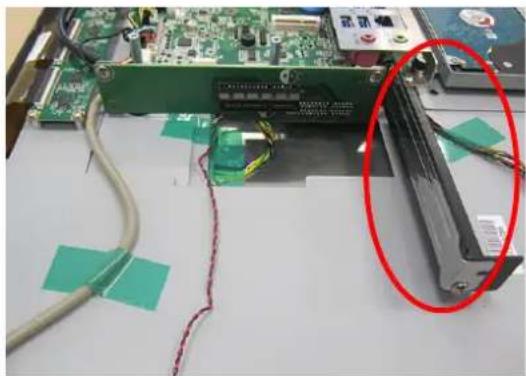
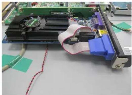
Remove the rear cover of the Panel PC. Then remove the screws and shield as indicated in the red circle in Fig 2.26 and install the expansion card.
-
The original machine provides PCIe x4 riser card (PCM-939), and the installation is shown as Fig 2.26 and 2.27).
-
The installation of expansion PCI riser card is shown as Fig 2.28 and Fig 2.29.
Note! The maximum dimensions of the expansion card is 167.65 mm x 106.7mm.

natural_image
Close-up of a green circuit board with visible wiring and components, no readable text or symbols present.Figure 2.26 Figure 2.27
natural_image
Interior view of a computer motherboard with CPU socket, heatsink, and cable wrapped around it (no visible text or symbols)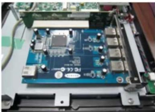
natural_image
Close-up of a blue printed circuit board with electronic components and connectors (no visible text or symbols)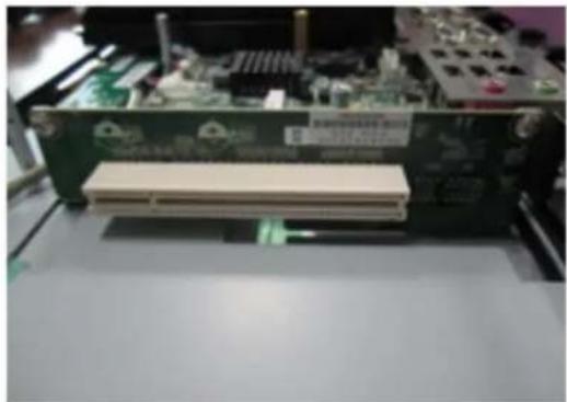
natural_image
Computer motherboard with a beige plastic component inserted into the case (no visible text or symbols)Figure 2.28 Figure 2.29
2.8 AT/ATX Function Switch
The switch is built in to the machine. Use it to choose AT/ATX functions without removing the rear cover.
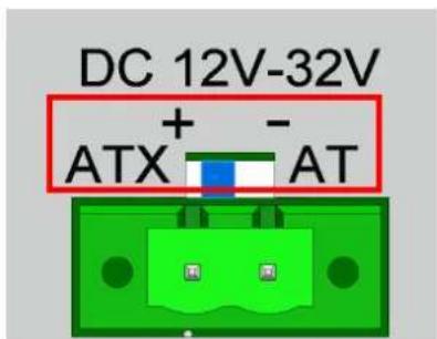
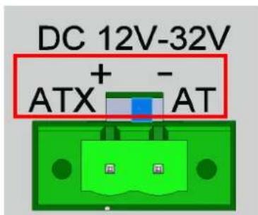
Figure 2.30 ATX mode Figure 2.31 AT mode
2.9 Grounding Installation
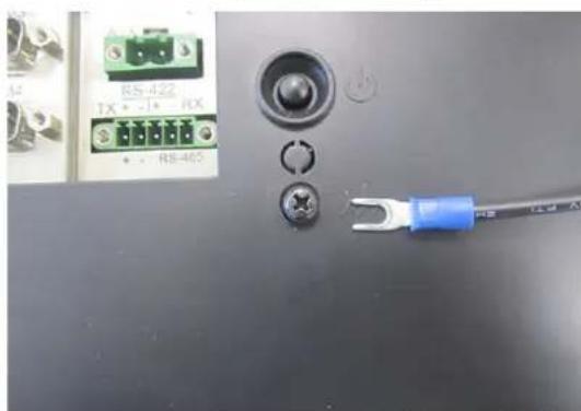
Loosen the screws, remove down the plastic cover, plug in the grounding cable, and then fix the screws. (See Fig 2.32 \~ Fig 2.35)
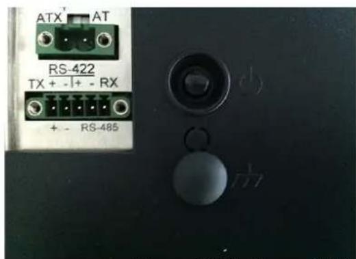
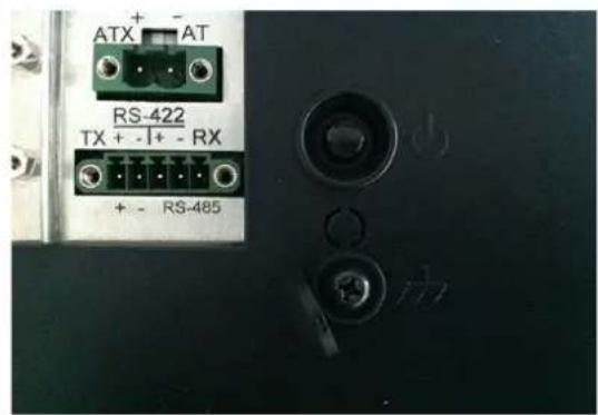
Figure 2.32 Figure 2.33
natural_image
Close-up of electronic components including a power connector, switch, and terminal block (no visible text or symbols)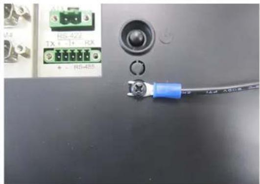
natural_image
Close-up of a black electronic device with a blue plastic connector and labeled ports (no readable text or symbols)Figure 2.34 Figure 2.35
Note! The grounding cable is not provided in the accessory box.

2.10 Hook Installation
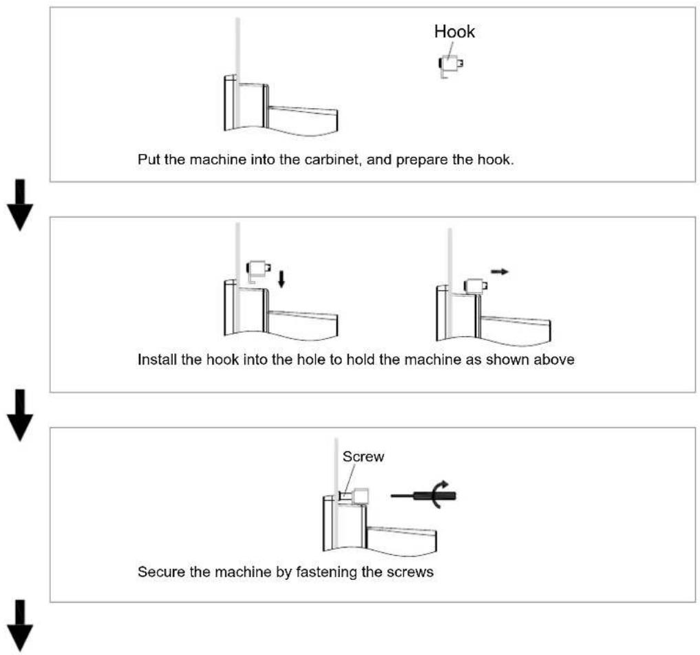
Follow the figures below:
flowchart
graph TD
    A["Put the machine into the cabinet, and prepare the hook."] --> B["Install the hook into the hole to hold the machine as shown above"]
    B --> C["Secure the machine by fastening the screws"]
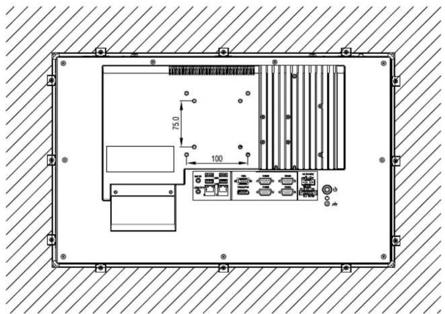
Figure 2.36 Hook Installation
2.11 Solo Quick Installation
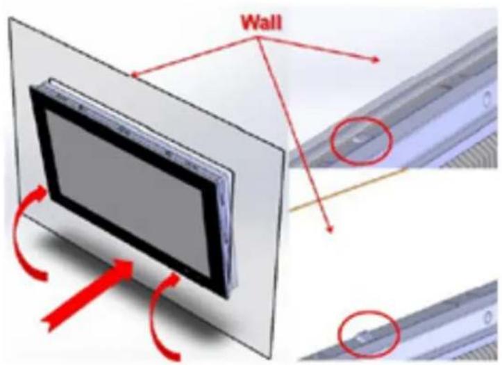
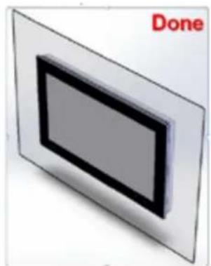
Users can independently complete the panel wallmount installation by quick installation Guide. Follow the procedures below:
- Loosen the two screws at the base, see the figure below.
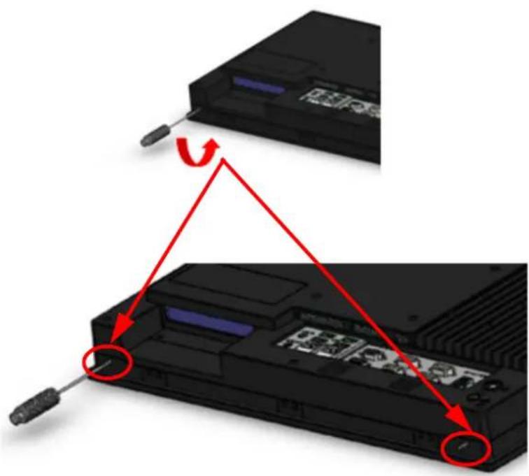
- Push the machine into a gap in the wall, the spring hook will lock the machine into the wall.
- Installation is complete as shown in the figure below. Then in the rear of the machine, lock the hook screw and fix the machine according to Section 2.10 "Hook Installation".
natural_image
3D rendering of a rectangular panel with a black border and gray interior, labeled 'Done' in red text (no other symbols or text)Note! It is recommend that the mount thickness is smaller than 2 mm (0.079") according to quick installation guide. For other situations, the recommended thickness is less than 6 mm (0.236").
Chapter 3
Jumper Configuration
Sections include:
Jumper & Connectors
■ External COM Port Pin Definition
3.1 Jumper & Connectors
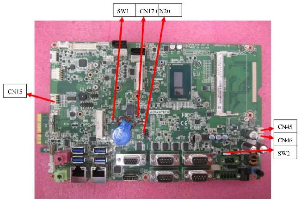
Figure 3.1 PCM-8209 front view
SW1 Panel Resolution Selection
| Setting | Function |
| 1000 | for 15.6" LCD |
| 1110 | for 21.5" LCD |
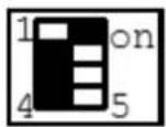
1000 setting for 15.6" LCD
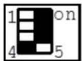
1110 setting for 21.5" LCD
CN20 COM1/COM2 RI Type Select
| Description For COM1/COM2 select RI Voltage mode |
| Setting Function |
| (1-3) (2-4) (default) RI |
| (3-5) (4-6) 5V |
| (7-9) (8-10) 12V |

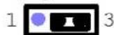
CN17 clean CMOS
Setting Function
(1-2) Clear CMOS
(2-3) Keep CMOS (default)
Clear CMOS
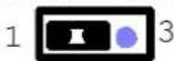
Keep CMOS
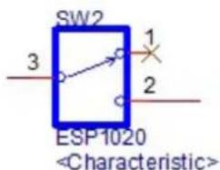
SW2 ATX/AT Mode Selection
Pin Pin Name
1-3 ATX Power(default)
2-3 AT Power
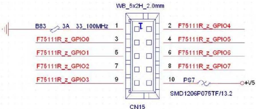
CN15 GPIO
Pin Pin Name
| 1 | GND | ||
| 2 | G | P | I |
| 3 | G | P | I |
| 4 | G | P | I |
| 5 | G | P | I |
| 6 | G | P | I |
| 7 | G | P | I |
| 8 | G | P | I |
| 9 | GPIO3 | ||
| 10 | 5V | ||
3.2 External COM Port Pin Definition
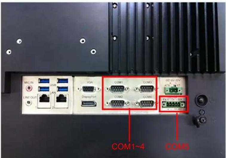
Figure 3.2 COM ports
COM 1 and COM 2 (RS232, pin9 supports 5 V/12 V output)
COM 3 and COM 4 (RS232)
COM 5 RS-422/485
Note!COM4 doesn't support RING function.

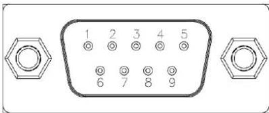
COM1-4:
| Pin COM1 / COM2 COM3 / COM4 | ||
| 1 DCD DCD | ||
| 2 | R | X |
| 3 | T | X |
| 4 | D | T |
| 5 | G | N |
| 6 | D | S |
| 7 | R | T |
| 8 | C | T |
| 9 RING or 5V/12V output RING (Only COM3) | ||
Pin9 is set as RI signal in COM port by default, and could be set as 5V/12V output by Jumper
COM5: RS422/485 with Isolation 1000 VDC, BIOS selectable
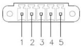
| P | i | n | 1 | 2 | 3 | 4 |
| RS422 TX+ TX- RX+ RX- GND | ||||||
| RS485 D+ D- GND | ||||||
UART RS485 Auto Flow Control
COM5 supports RS485 auto flow control function for all UART.
When enabling the RS485 auto control function, it will automatically drive RTS# pin to logic high or low for flow control.
To make this RS485 auto flow control function work, please be noted that the parity and stop-bit setting has to be one of the following three settings:
(1) 8 data bits + 1 parity bit + 1 stop bit
(2) 8 data bits + 1 parity bit + 2 stop bits
(3) 8 data bits + 2 stop bits
Chapter 4
Software
Configuration
Sections include:
Installing Drivers
BIOS Setup Program
4.1 Install Divers
When first using the system, users need to set up corresponding drivers, in order to ensure all functions are normal. Remove the DVD-ROM from the accessory box and open it in the system:
Follow the instructions to install the drivers. The drivers in the accompanied DVD-ROM may not be the latest version, if needed, find it at:
http://www.advantech.com/
4.2 BIOS Setup
4.2.1 Enter BIOS
Start the computer and press the "Delete" key to enter BIOS.
Press "F4" to save and exit after any configuration, or the configuration won't be saved in BIOS.
![Aptio Setup Utility - Copyright (C) 2012 American Megatrends, Inc. Main Advanced Chipset Boot Security Save & Exit BIOS Information BIOS Vendor American Megatrends Core Version 4.6.5.4 0.32 x64 Compliance UEFI 2.3.1; PI 1.2 Project Version PCM 8209XP07 Build Date and Time 03/19/2014 15:03:19 System Date [Sun 06/04/2000] System Time [23:00:57] Set the Date. Use Tab to switch between Date elements. +: Select Screen ↓: Select Item Enter: Select +/-: Change Opt. F1: General Help F2: Previous Values F3: Optimized Defaults F4: Save & Exit ESC: Exit Version 2.15.1236. Copyright (C) 2012 American Megatrends, Inc.](/content/2026/05/975456/images/0049378c5ef23f2e3f2d380547d7f2e1ff207862d8002acb2d4151335928607e.jpg)
4.2.2 Display Brightness Adjustment
1. Select "Brightness Control" under "Chipset".
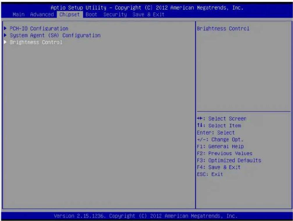
2. Select "Brightness Manual Control" under "Brightness Control", and there will be six [6] options:
![Aptio Setup Utility - Copyright (C) 2012 American Megatrends, Inc. Chipset Brightness Control LCD Brightness Control [Manual Mode] Brightness Manual Control [80%] Brightness Manual Control 100% 80% 60% 40% 20% 10% Fixed Brightness 100%, 80% 60%, 40%, 20%, 10% Select Screen Select Item er: Select : Change Opt. F1: General Help F2: Previous Values F3: Optimized Defaults F4: Save & Exit ESC: Exit Version 2.15.1236. Copyright (C) 2012 American Megatrends, Inc.](/content/2026/05/975456/images/8b95d820e905ceb649d346ad30c9603565331e9c6576bb0aff748faeb7f74eca.jpg)
Note! If you want to adjust brightness through AP in the OS, it will keep AP configuration mainly, and BIOS configuration will not be saved.
![Advantech PPC-4211W - Select "Brightness Manual Control" under "Brightness Control", and there will be six [6] options: - 2](/content/2026/05/975456/images/f08623456c007ce27e3612f1d83e8177c360d6ad8be3f3871c91ef0d845faf2a.jpg)
4.2.3 COM5 Mode Selection (RS422/485)
- Select "Super IO Configuration" under "Advanced".
![Aptio Setup Utility - Copyright (C) 2012 American Megatrends, Inc. Main Advanced Chipset Boot Security Save & Exit Legacy OpROM Support Launch PXE OpROM [Disabled] ▶ ACPI Settings ▶ CPU Configuration ▶ SATA Configuration ▶ AMT Configuration ▶ USB Configuration ▶ Super IO Configuration ▶ Super IO HW Monitor System Super IO Chip Parameters. +: Select Screen ↑↓: Select Item Enter: Select +/-: Change Opt. F1: General Help F2: Previous Values F3: Optimized Defaults F4: Save & Exit ESC: Exit Version 2.15.1236. Copyright (C) 2012 American Megatrends, Inc.](/content/2026/05/975456/images/d285deb299dd3be51eb81503bfff7eb88c37a02ee5b74d97ab734b9354d14500.jpg)
- Select "Serial Port 5 Configuration" and then select the operation mode of COM5 by "Serial Port5 Mode".
![Optio Setup Utility - Copyright (C) 2012 American Megatrends, Inc. Advanced Serial Port 5 Configuration Device Settings IO=2DOh; IRQ=12; Serial Port 5 Mode [RS485] Serial Port 5 RS485 Terminate [Disabled] Serial Port 5 Mode RS485 RS422 Allows BIOS to Select mode for Serial Port 5. +: Select Screen ↑↓: Select Item Enter: Select +/-: Change Opt. F1: General Help F2: Previous Values F3: Optimized Defaults F4: Save & Exit ESC: Exit Version 2.15.1236. Copyright (C) 2012 American Megatrends, Inc.](/content/2026/05/975456/images/667538dbb883b1504a9abbf19f5faf120d7b5fdf24a58d463a755747dcdeb6c1.jpg)
4.2.4 Wake Up by LAN
1. Select "ACPI Settings" under "Advanced".
![Aptio Setup Utility - Copyright (C) 2012 American Megatrends, Inc. Main Advanced Chipset Boot Security Save & Exit Legacy OpROM Support Launch PXE OpROM [Disabled] ▶ ACPI Settings ▶ CPU Configuration ▶ SATA Configuration ▶ AMT Configuration ▶ USB Configuration ▶ Super IO Configuration ▶ Super IO HW Monitor System ACPI Parameters. +: Select Screen ↑↓: Select Item Enter: Select +/-: Change Opt. F1: General Help F2: Previous Values F3: Optimized Defaults F4: Save & Exit ESC: Exit Version 2.15.1236. Copyright (C) 2012 American Megatrends, Inc.](/content/2026/05/975456/images/8d02a7981b486486b0e16bcbbc982ded9a81bf20a8ec328cce1d8f0efe4870f7.jpg)
2. Set "Wake On By LAN or RI" as "Enabled".
![Aptio Setup Utility - Copyright (C) 2012 American Megatrends, Inc. Advanced ACPI Settings ACPI Sleep State [S1 only\CPU Stop Cl...] Power On by RTC Alarm [Disabled] Wake On by LAN or RI [Enabled] Enable or disable LAN or Ring to wake the system. +: Select Screen ↑↓: Select Item Enter: Select +/-: Change Opt. F1: General Help F2: Previous Values F3: Optimized Defaults F4: Save & Exit ESC: Exit Version 2.15.1236. Copyright (C) 2012 American Megatrends, Inc.](/content/2026/05/975456/images/92ce35719e8751f80747b156c22f97d996bb1009f2385d024c9ddf9ef695bfb5.jpg)
- Then save the configuration and exit the OS.
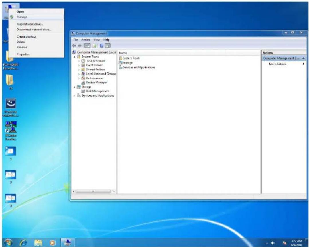
- Right click "Computer" and click "Manage", then open "Computer Management".
- Click "Network adapters" in "Device Management", then right click and select the needed LAN port, then select "Properties" and open "Intel(R) Ethernet".
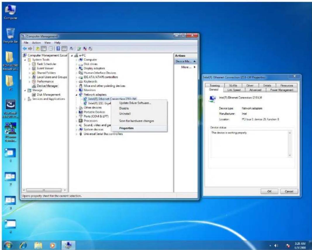
- Select "Work On Magic Packet", "Work On Pattern Match" and "Work On Magic Packet From Power Off State" under "Power Management".
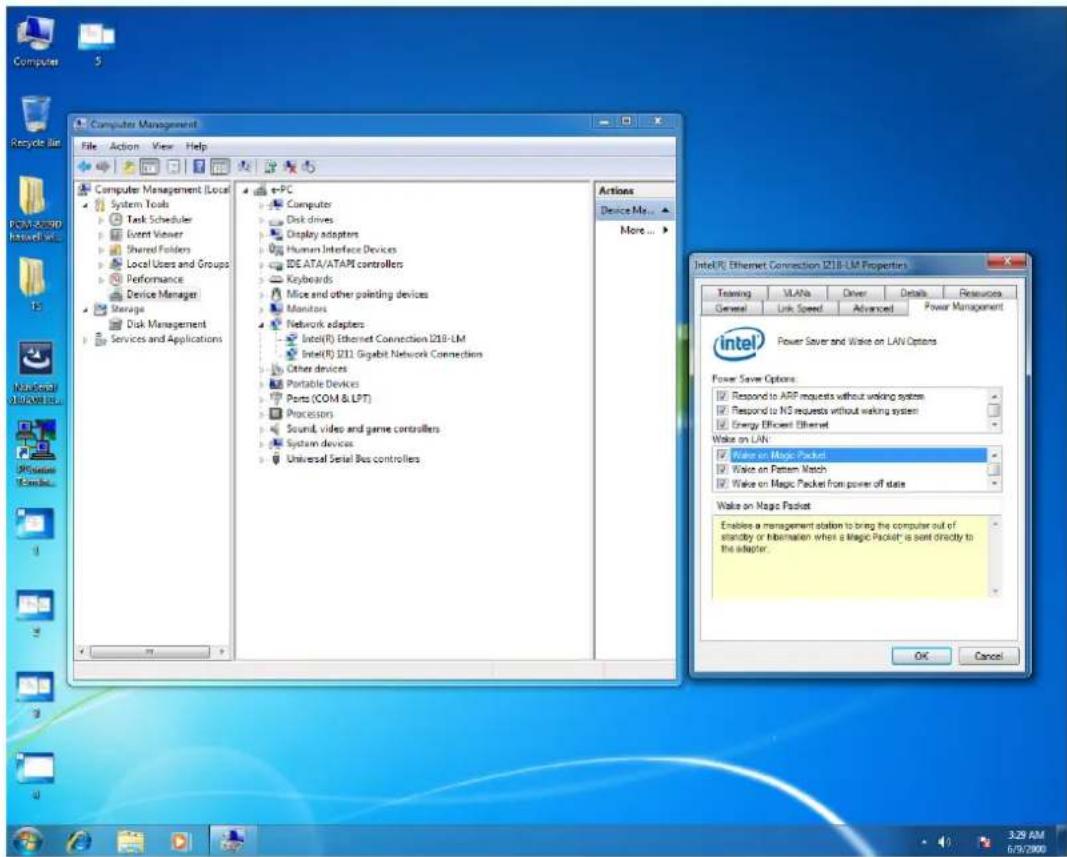
4.2.5 RAID Installation
- Enter BIOS when boot up, and click "SATA Configuration" under Advanced.
![Aptio Setup Utility - Copyright (C) 2012 American Megatrends, Inc. Main Advanced Chipset Boot Security Save & Exit Legacy OpROM Support Launch PXE OpROM [Disabled] ▶ ACPI Settings ▶ CPU Configuration ▶ SATA Configuration ▶ AMT Configuration ▶ USB Configuration ▶ Super IO Configuration ▶ Super IO HW Monitor SATA Device Options Settings +: Select Screen ↑↓: Select Item Enter: Select +/-: Change Opt. F1: General Help F2: Previous Values F3: Optimized Defaults F4: Save & Exit ESC: Exit Version 2.15.1236. Copyright (C) 2012 American Megatrends, Inc.](/content/2026/05/975456/images/78bb440b9ae17229756e6e6aa95b723725e0bbbaf319ce0a243ac1e9f8515407.jpg)
- Set "SATA Mode Selection" as "RAID", then save and exit.
![Aptio Setup Utility - Copyright (C) 2012 American Megatrends, Inc. Advanced SATA Mode Selection [RAIDI] SATA Controller Speed [Default] Serial ATA Port 0 Empty SATA Device Type [Hard Disk Drive] Serial ATA Port 1 ST500LT012-1DG (500.1GB) SATA Device Type [Hard Disk Drive] Serial ATA Port 2 ST500LT012-1DG (500.1GB) SATA Device Type [Hard Disk Drive] Determines how SATA controller(s) operate. +: Select Screen ↑↓: Select Item Enter: Select +/-: Change Opt. F1: General Help F2: Previous Values F3: Optimized Defaults F4: Save & Exit ESC: Exit Version 2.15.1236. Copyright (C) 2012 American Megatrends, Inc.](/content/2026/05/975456/images/a8305438f86fd5cb8ff4eb28890510e620387828fba013b0f01c7b84bd850a36.jpg)
- Press "Ctrl + I" to enter RAID configuration utility when entering the second start-up screen.
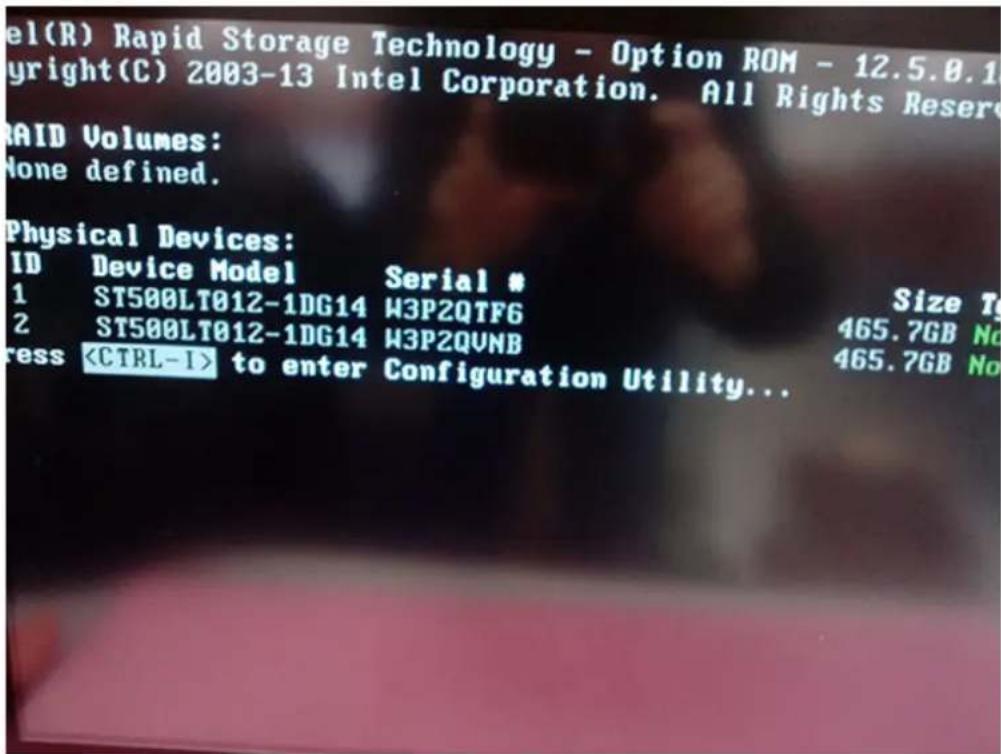
- Enter "Create RAID Volume".
![Intel(R) Rapid Storage Technology - Option ROM - 12.5.0.1815 Copyright(C) 2003-13 Intel Corporation. All Rights Reserved. [ MAIN MENU ] 1. Create RAID Volume 2. Delete RAID Volume 3. Reset Disks to Non-RAID 4. Recovery Volume Options 5. Acceleration Options 6. Exit [ DISK/VOLUME INFORMATION ] RAID Volumes: None defined. Physical Devices: ID Device Model Serial # 1 ST500LT012-1DG14 W3P2QTF6 2 ST500LT012-1DG14 W3P2QVNB Size Type/Status(Vol ID) 465.7GB Non-RAID Disk 465.7GB Non-RAID Disk](/content/2026/05/975456/images/2a59f0b52967ba6dbab766a26a8b87363fe7c4dd2fdc3c36618a214657e4fd5e.jpg)
- Input "Name" and select "RAID Level", and then save and exit "Create Volume" menu.
![Intel(R) Rapid Storage Technology - Option ROM - 12.5.0.1815 Copyright(C) 2003-13 Intel Corporation. All Rights Reserved. [ CREATE VOLUME MENU ] Name: Volume1 RAID Level: ROLD1(Mirror) Disks: Select Disks Strip Size: N/A Capacity: 465.8 GB Sync: N/A Create Volume [ HELP ] RAID 1: Mirrors data (redundancy). [↑↓]Change [TAB]-Next [ESC]-Previous Menu [ENTER]-Select](/content/2026/05/975456/images/4dc2a0248d4f2e9e814272f9ed920174c79f408af75abe95820a575cb429e1de.jpg)
- Click "Exit", the device will start the normal RAID installation.
![Intel(R) Rapid Storage Technology - Option ROM - 12.5.8.1815 Copyright(C) 2003-13 Intel Corporation. All Rights Reserved. [ MAIN MENU ] 1. Create RAID Volume 2. Delete RAID Volume 3. Reset Disks to Non-RAID 4. Recovery Volume Options 5. Acceleration Options 6. Exit [ DISK/VOLUME INFORMATION ] RAID Volumes: ID Name Level Strip Size Status Bootable 0 Volume1 RAID1(Mirror) N/A 465.8GB Normal Yes Physical Devices: ID Device Model Serial # 1 ST500LT012-1DG14 W3P2QTF6 2 ST500LT012-1DG14 W3P2QVNB Size Type/Status(Vol ID) 465.7GB Member Disk(0) 465.7GB Member Disk(0) [↑↓]-Select [ESC]-Exit [ENTER]-Select Menu](/content/2026/05/975456/images/253e99b019636795871cb6deaa5bea67614090ee781b9bda99349c50fe231d75.jpg)
- Take out the OS setup disk when you see this screen, then insert the driver disk and click "Load driver".
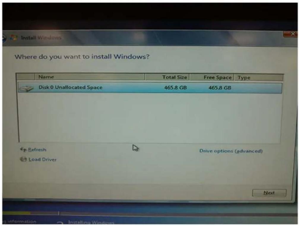
- Select RAID driver folder and click "OK".
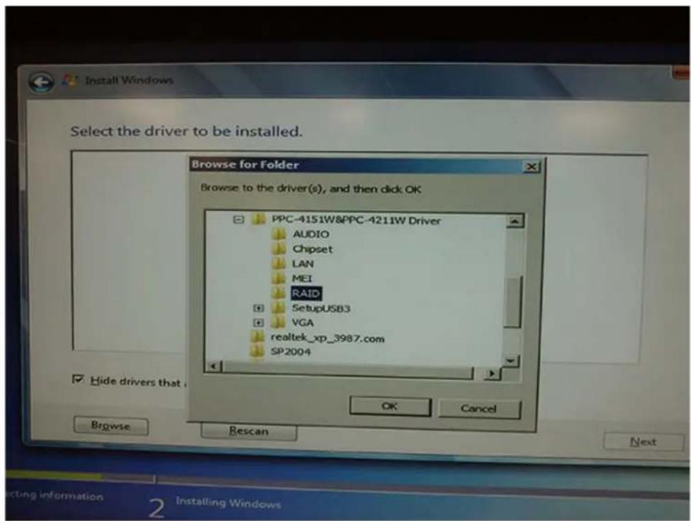
9. Click "Next".
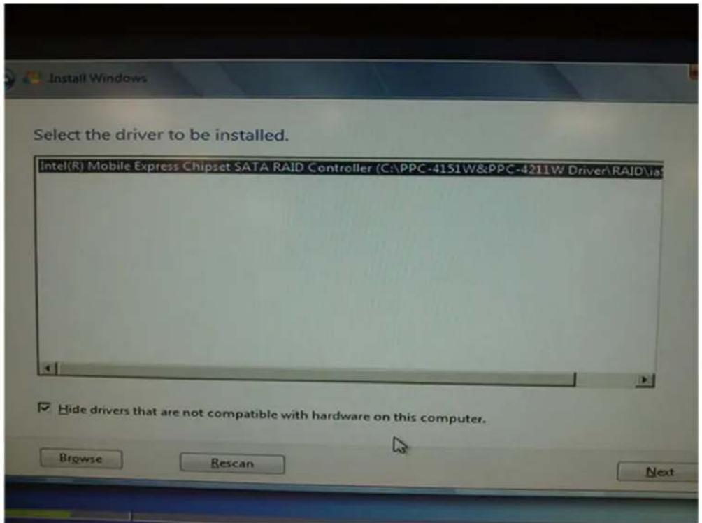
10. Replace the driver disk with system setup disk after installation of RAID driver is finished, then click "Next" to return the normal system installation.
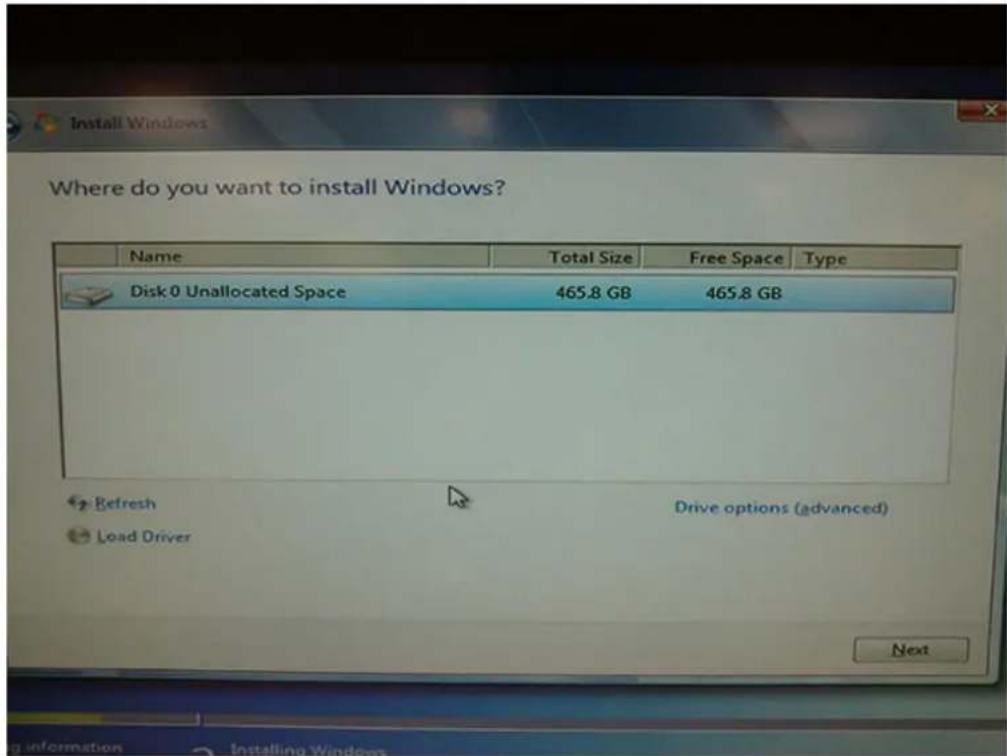
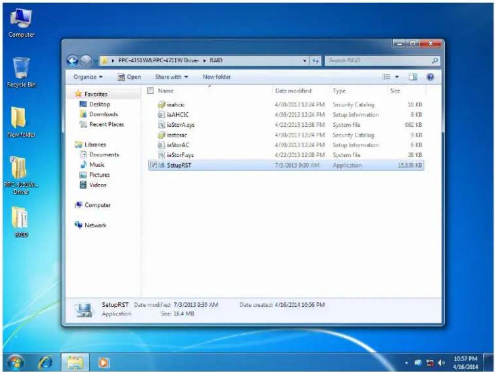
- After installing all the drivers, click the "SetupRST.exe" in the driver folder.
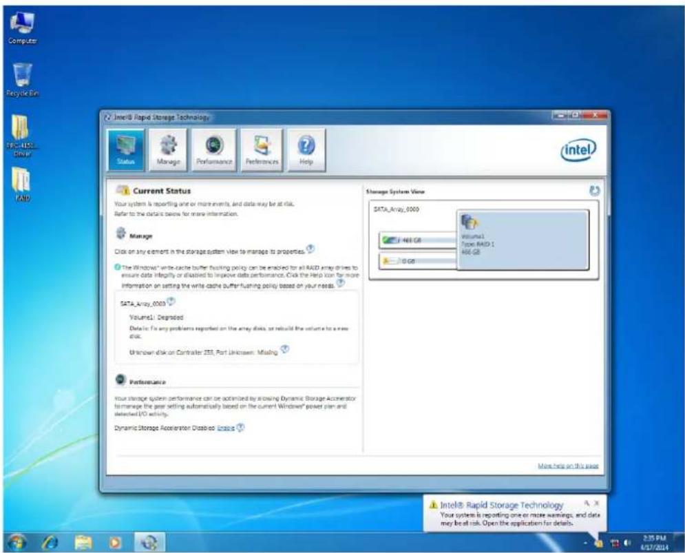
- Click the icon in the lower-right corner of the screen to check the working status of RAID Volume.
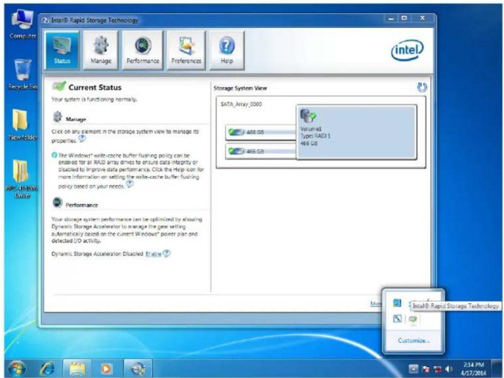
- If RAID 1 mode is installed and when one the HDDs fails, a pop-up message will appear in the lower right corner. Click the message box to check details of the problem.
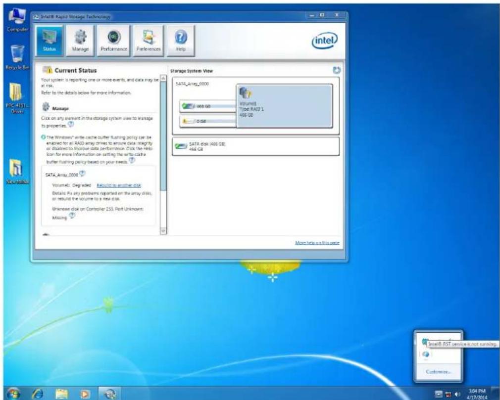
- At this time, you will need to turn off the computer to change the failed HDD. After entering the system, click "Rebuild to another disk" to back up the system to the new hard disk.
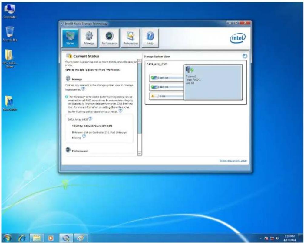
- When the rebuilding status shows 100%, system backup is complete and RAID 1 function will work again.
www.advantech.com
Please verify specifications before quoting. This guide is intended for reference purposes only.
All product specifications are subject to change without notice.
No part of this publication may be reproduced in any form or by any means, electronic, photocopying, recording or otherwise, without prior written permission of the publisher.
All brand and product names are trademarks or registered trademarks of their respective companies.
© Advantech Co., Ltd. 2014
- PPC-4211W
- Copyright
- Acknowledgements
- Product Warranty (2 years)
- Declaration of Conformity
- CE
- FCC Class B
- Technical Support and Assistance
- Safety Instructions
- Safety Precaution - Static Electricity
- Battery Information
- Contents
- Chapter 1 General Information ....1
- Chapter 2 System Installation & Setup ....5
- Chapter 3 Jumper Configuration ...... 19
- Chapter 4 Software Configuration ...... 25
- Chapter 1
- General Information
- Introduction
- Specifications
- General Specification
- Power Specifications
- Touchscreen Specifications
- Environment Specifications
- Certification Specifications
- IP
- Dimensions
- Chapter 2
- System Installation & Setup
- Sections include:
- Quick Start Guide
- I/O interfaces:
- Installation Procedures
- Connecting the Power Cable
- Connecting the Keyboard and Mouse
- Power ON
- Install Memory Card
- Installing the HDD
- Installing Mini SATA
- Installing Wireless LAN Card
- Installing the Riser Card
- AT/ATX Function Switch
- Grounding Installation
- Hook Installation
- Solo Quick Installation
- Chapter 3
- Jumper Configuration
- Jumper & Connectors
- CN17 clean CMOS
- Setting Function
- SW2 ATX/AT Mode Selection
- Pin Pin Name
- CN15 GPIO
- External COM Port Pin Definition
- UART RS485 Auto Flow Control
- Chapter 4
- Software
- Configuration
- Install Divers
- BIOS Setup
- Enter BIOS
- Display Brightness Adjustment
- Select "Brightness Control" under "Chipset".
- Select "Brightness Manual Control" under "Brightness Control", and there will be six [6] options:
- COM5 Mode Selection (RS422/485)
- Wake Up by LAN
- Select "ACPI Settings" under "Advanced".
- Set "Wake On By LAN or RI" as "Enabled".
- RAID Installation
- Click "Next".
- Replace the driver disk with system setup disk after installation of RAID driver is finished, then click "Next" to return the normal system installation.
- www.advantech.com
Brand : Advantech
Model : PPC-4211W
Category : Desktop computer