
VX45 - Vacuum Cleaner ZODIAC - Free user manual and instructions
Find the device manual for free VX45 ZODIAC in PDF.


| Product Type | Robotic Pool Cleaner |
| Brand | Zodiac |
| Model | VX45 |
| Dimensions (L x W x H) | 46 x 46 x 33 cm |
| Weight | 11.5 kg |
| Power Supply | 230 V / 50 Hz |
| Power Consumption | 200 W |
| Cable Length | 18 m |
| Filtration System | Ultra-fine filter cartridge (10 µm) |
| Navigation | Random with gyroscope |
| Cleaning Coverage | Floor, walls, waterline |
| Max Pool Size | 12 x 6 m |
| Suction Motor | Dual drive brushless |
| Drive System | Tracks with anti-slip pattern |
| Control | Automatic cycle (2.5 hours) |
| Waterproof Rating | IP68 |
| Filter Cleaning | Easy-open lid, rinse with hose |
| Recommended Maintenance | Clean filter after each use, check tracks monthly |
| Safety Features | Automatic shut-off when lifted, low voltage transformer |
| Spare Parts Available | Filter cartridges, tracks, brushes, motor |
| Repairability Index | 8/10 (modular design) |
Frequently Asked Questions - VX45 ZODIAC
User questions about VX45 ZODIAC
0 question about this device. Answer the ones you know or ask your own.
Ask a new question about this device
Download the instructions for your Vacuum Cleaner in PDF format for free! Find your manual VX45 - ZODIAC and take your electronic device back in hand. On this page are published all the documents necessary for the use of your device. VX45 by ZODIAC.
USER MANUAL VX45 ZODIAC
natural_image
Line drawing of a toy car with wheels and a textured grip (no text or symbols)TYPE EC15--
vx40
vx45
4WD
vx50
4WD
vx55
4WD
VORTEX-PRO™
Robotic Pool Cleaner
Owner's Manual
WARNING
FOR YOUR SAFETY - For anything other than the routine cleaning and maintenance described in this manual, this product must be serviced by a pool technician who is licensed and qualified in pool equipment by the jurisdiction in which the product will be installed where such state or local requirements exist. In the event no such state or local requirement exists, the pool technician must be a professional with sufficient experience in pool equipment installation and maintenance so that all of the instructions in this manual can be followed exactly. Improper installation and/or operation will void the warranty.
Table of Contents
Section 1. Important Safety Instructions......3
Section 2. Cleaner Specifications ....4
2.1 General Specifications 4
Section 3. Assembly......4
3.1 Unpacking 4
3.2 Assembling the Transport Caddy (VX50 4WD and VX55 4WD) 5
3.3 Connecting the Control box to Caddy (VX50 4WD / VX55 4WD) or Base (VX40 / VX45 4WD)....7
3.4 Connecting Floating Cable to Control Box ..... 7
Section 4. Operation......8
4.1 Submerging the Cleaner 9
4.2 The VX40 Cleaner Control box 10
4.3 The VX45 4WD and VX50 4WD
Cleaner Control box .... 10
4.4 The VX55 4WD Cleaner Control box .....11
4.5 Starting the Cleaner ..... 11
4.6 Stopping the Cleaner and Removing from the Pool....12
4.7 Operating the Cleaner with the Remote Control (VX55 4WD only) ..... 12
4.8 Synchronizing the Remote Control....13
4.9 Storing the Cleaner 13
Section 5. Programming the Cleaner .... 14
5.1 Displaying Current Day and Time....14
5.2 Changing the Clock Day and Time....14
5.3 Changing Default Cleaning Times....14
5.4 Programming Cleaning Cycles....15
5.5 Canceling Cleaning Cycles 15
Section 6. Cleaning and Maintenance ..... 16
6.1 Cleaning the Filter Canister.... 16
6.2. Cord Tangling 17
6.3 Replacing the Brushes 18
6.4 Replacing the Tyres.... 19
Section 7. Troubleshooting ...... 21
7.1 Using the Information LED for Troubleshooting (VX40 Cleaner)....21
7.2 Viewing Cleaner Status Information for Troubleshooting (VX45 4WD, VX50 4WD, and VX55 4WD)....21
7.3 General Troubleshooting 22
7.4 Control Box Error Codes (VX45 4WD, VX50 4WD and VX55 4WD)....23
THANK YOU FOR PURCHASING THIS ROBOTIC POOL CLEANER BY ZODIAC®.
YOUR CLEANER HAS BEEN DESIGNED AND MANUFACTURED TO BE EASILY INSTALLED AND TO PROVIDE LOW MAINTENANCE OPERATION. A WARRANTY CARD IS SUPPLIED IN THE BOX. PLEASE GO TO ZODIAC.COM.AU TO REGISTER FOR WARRANTY.
Taking these steps will help ensure prompt warranty service, should it be required. If service is required, please contact your original dealer. If the original dealer does not perform warranty service, please visit www.zodiac.com.au to locate an independent service company near you. If you are unable to locate a service company, please call our After Sales Support Team at 1300 763 021.
In the case your product may require a service or warranty repair, please retain the original carton to transport your cleaner in.
Section 1. Important Safety Instructions
Congratulations on purchasing the Zodiac robotic cleaner. Please read through the entire manual before installing the cleaner. Your cleaner must be installed and operated as specified.
READ AND FOLLOW ALL INSTRUCTIONS
WARNING
Failure to comply with the following warnings can increase risk of fire or electrocution which can result in property damage and serious injury, including loss of life.
PREVENT ELECTRICAL SHOCK
To reduce risk of electrical shock:
- The cleaner is to be installed in accordance with the relevant requirements of the Australian wiring rules AS/NZS 3000. Also refer to the installation instructions relating to the swimming pool equipment for which the cleaner will be an integral part. The cleaner is to be supplied through a Residual Current Device (RCD) with a rated residual operating current of 30mA .
- Do not enter pool while the robotic cleaner is in water.
- Do not bury cord. Locate cord so as to prevent it from being damaged by lawn mowers, hedge trimmers and other equipment.
• To reduce the risk of electrical shock, do not use the robotic cleaner or control box if the cord is worn or damaged. Contact Zodiac Customer Care Service 1300 763 021 immediately for proper servicing and replacement of the damaged cord. - Double insulation—For continued protection against possible electric shock, use only identical replacement parts when servicing. Do not attempt repair of the robotic cleaner, control box, power cord, or floating cable.
- Use only the power supply provided with the product.
• NEVER OPEN Control box. - DO NOT USE AN EXTENSION CORD TO CONNECT THE UNIT TO ELECTRIC SUPPLY; PROVIDE A PROPERLY LOCATED RCD PROTECTED POWER OUTLET. THE CONTROL BOX SHOULD BE PLACED NEAR THE RCD PROTECTED POWER OUTLET POINT.
PREVENT CHILD INJURY AND DROWNING
- To reduce the risk of injury, do not permit children or persons with reduced physical, sensory or mental capabilities, or lack of experience and knowledge to operate this product.
- Do not let anyone, especially small children, sit, step, lean, or climb on any equipment installed as part of your pool's operational system.
CAUTION
Failure to comply with the following warnings could cause damage to pool equipment or personal injury.
- The robotic cleaner must be installed and operated as specified.
- This product is intended for use with permanently-installed pools. Do not use with storable pools. A permanently-installed pool is constructed in or on the ground or in a building such that it cannot be readily disassembled for storage. A storable pool is constructed so that it is capable of being readily disassembled for storage and reassembled to its original integrity.
- Clean the filter canister after each use.
- Do not use the product in your pool if the water temperature is above 35^ (95°F) or below 13^ (55°F).
CAUTION
USE OF THE ZODIAC ROBOTIC CLEANER IN A VINYL LINER POOL
Certain vinyl liner patterns are particularly susceptible to rapid surface wear of pattern removal caused by objects coming into contact with the vinyl surface, including pool brushes, pool toys, floats, fountains, chlorine dispensers, and automatic pool cleaners. Some vinyl liner patterns can be seriously scratched or abraded simply by rubbing the surface with a pool brush. Ink from the pattern can also rub off during the installation process or when it comes into contact with objects in the pool. Zodiac Pool Systems, Inc., is not responsible for, and the Limited Warranty does not cover, pattern removal, abrasion or markings on vinyl liners.
SAVE THESE INSTRUCTIONS
Section 2. Cleaner Specifications
2.1 General Specifications
The general specifications for the cleaner are as follows:
| Control boxsupplyvoltage | 220-240 VAC, 50 Hz; short circuit-proofsafety isolating type |
| Supply voltage 30 V DC | |
| Installed load 150 W max | |
| Cable length | VX45 4WD: 15mVX40/ / VX50 4WD: 18mVX55 4WD: 21m |
| Cleaner size(WxDxH) | 43 x 48 x 27 cm |
| Weight of Cleaner 9.5 kg | |
| Packed weight 19 kg | |
| Filtration | All-purpose filter canister |
| Cycle lengths Variable program | amming for cleaningfl oor, walls, and waterline.From 1.5 - 3.0 hours. |
| Filter Canister | 200 microns |
The cleaner is a double-insulated product. A double-insulated electrical appliance is one which has been designed in such a way that it does not require a safety connection to ground. The basic requirement for double-insulation is that no single failure can result in dangerous voltage becoming exposed so that it might cause an electric shock and that this is achieved without relying on an earthed (grounded) metal casing. This is achieved by having two (2) layers of insulating material surrounding live parts or by using reinforced insulation. Therefore, devices having double-insulated construction, such as this cleaner, do not utilize a grounded (three-prong) cord/plug.
Section 3. Assembly
3.1 Unpacking
The packaging should contain the following items:
- Robotic cleaner
- Control box
• Control box base (VX40 and VX45)
• Remote Control (VX55 4WD only)
• Transport and storage caddy assembly components (VX50 4WD and VX55 4WD only)
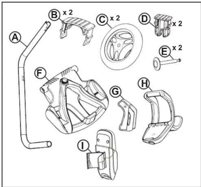
Figure 1. Transport Caddy Assembly Components (VX50 4WD / VX55 4WD)
(a) handle frame
(b) support blocks (x 2)
(c) wheels (x 2)
(d) wheel locking clips (x 2)
(e) wheel axle / hubcap (x 2)
(f) base unit
(g) cleaner hook
(h) caddy handle
(i) remote control hook (VX55 4WD only)
When unpacking the cleaner and its components:
- Check to make sure each component is in the box.
- Check cleaner and components for damage during transport.
- If there are any missing parts or damage, contact Zodiac® at 1300 763 021.
3.2 Assembling the Transport Caddy (VX50 4WD and VX55 4WD)
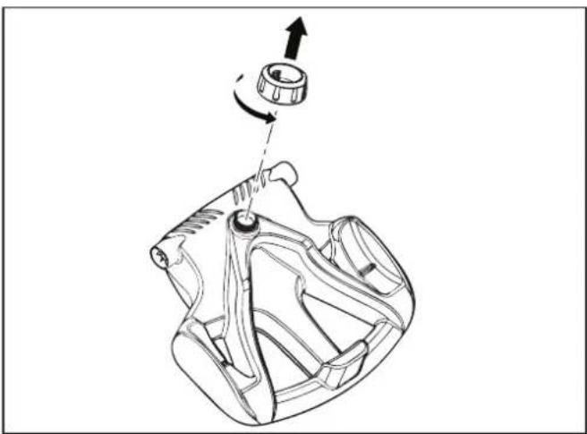
- Unscrew the handnut from the base unit (Figure 2).
natural_image
Technical line drawing of a mechanical component with a rotating shaft and adjustment knob (no text or symbols)Figure 2. Remove Handnut from Base Unit
-
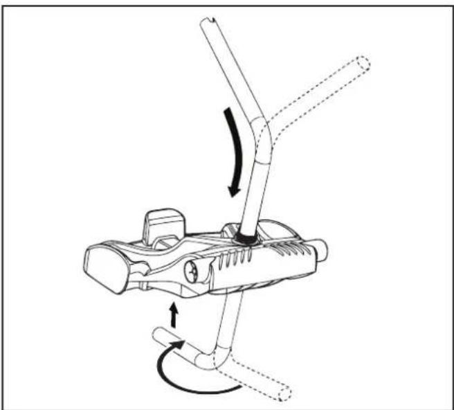
Insert the metal handle frame tubing into the base unit with notch end at the top, then rotate so the bends are away from you. (Figure 3)
-
Push base unit down (Figure 3) so the metal handle frame is seated in the recess on the underside of the base.
natural_image
Diagram of a mechanical device with directional arrows indicating motion or force (no text or symbols)Figure 3. Connect Metal Frame to Base Unit
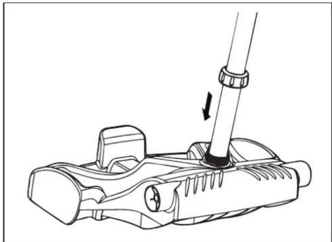
- Slide the handnut over the tube and twist to tighten onto base unit (Figure 4).
natural_image
Line drawing of a mechanical device with a lever and adjustment arrow (no text or symbols)Figure 4. Twist Handnut to Secure Frame
-
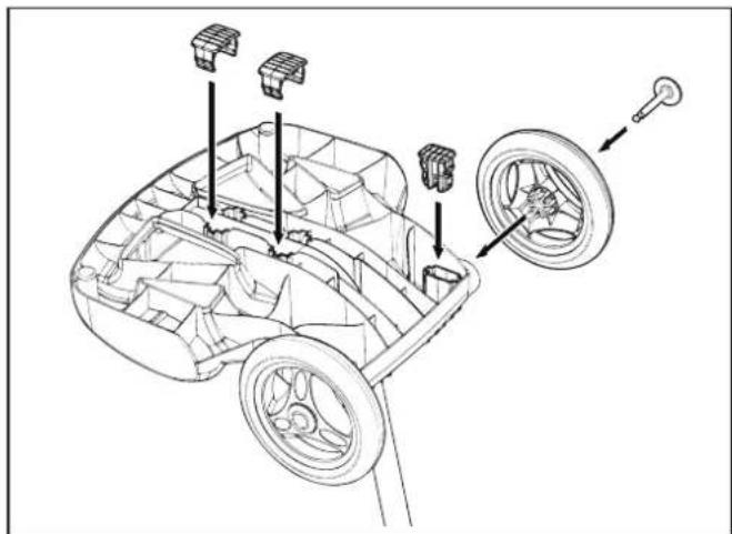
Snap two (2) support blocks into place (Figure 5).
-
Slide axle and hubcap piece through center of wheel and attach to base unit. Snap locking clip into place to secure wheel. Repeat to attach both wheels (Figure 5).
natural_image
Technical line drawing of a car chassis with labeled components (no text or symbols)Figure 5. Snap in Support Blocks and Attach Wheels
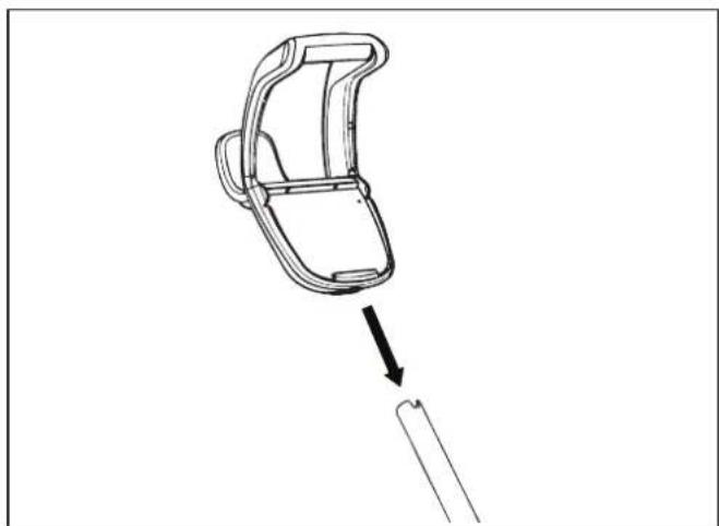
- Slide the control box base / caddy handle attachment down over the metal tubing until it snaps into place. (See Figure 6).
natural_image
Line drawing of a mechanical component with an arrow indicating direction (no text or symbols)Figure 6. Attach Caddy Handle
- Align cleaner hook pins with the top holes in the handle tube and snap into place (Figure 7).
natural_image
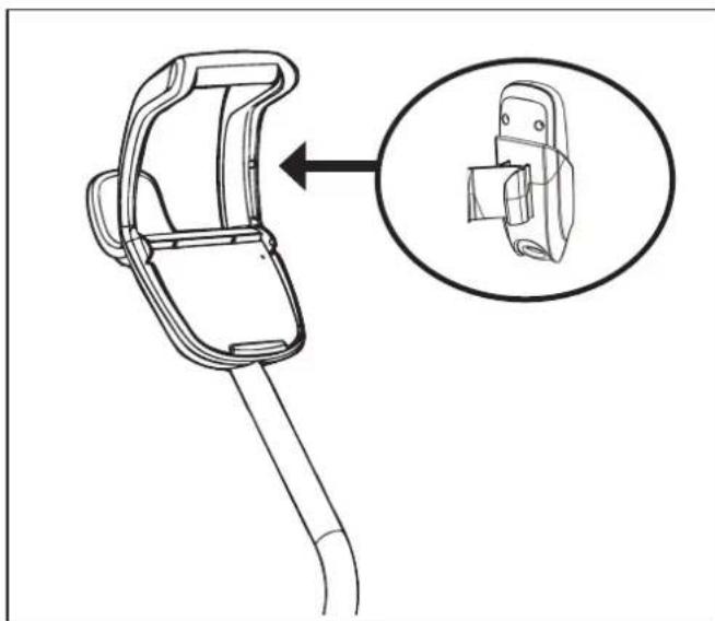
Technical line drawing of a mechanical clamp or bracket with an inset close-up showing the internal component (no text or symbols)Figure 8. Snap Remote Control Holder into Place
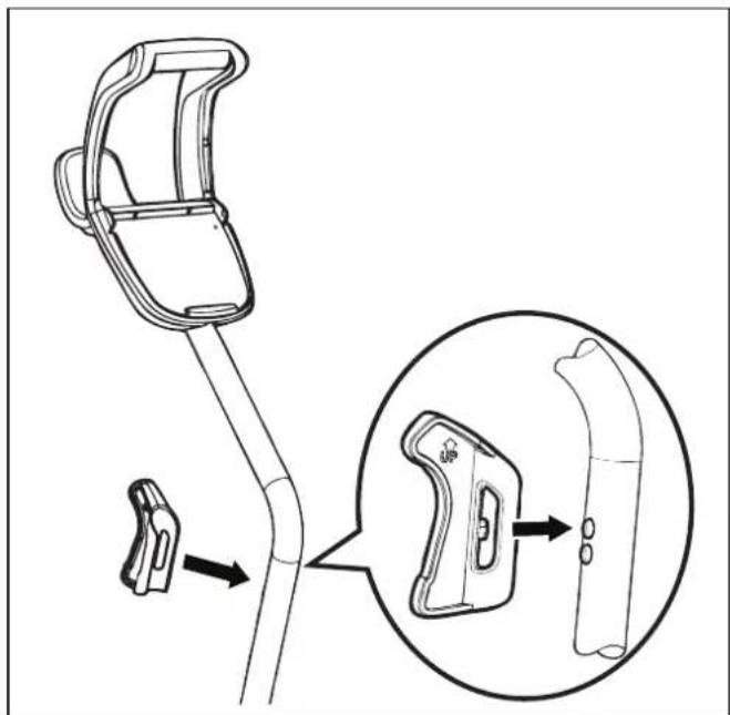
Figure 7. Snap Cleaner Hook into Place
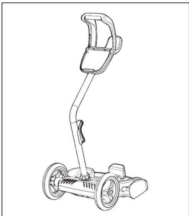
natural_image
Line drawing of a mobile phone with a mounted sensor device (no text or symbols)Figure 9. Fully Assembled Transport Caddy
- (VX55 4WD only) Locate pin on the remote control holder and align it with the recepticle on the handle of the caddy to attach the remote control box to caddy (Figure 8).
3.3 Connecting the Control box to Caddy (VX50 4WD / VX55 4WD) or Base (VX40 / VX45 4WD)
VX50 4WD / VX55 4WD:
- Align the bottom of the control box with the notch at bottom of the control box hook on the caddy (Figure 10).
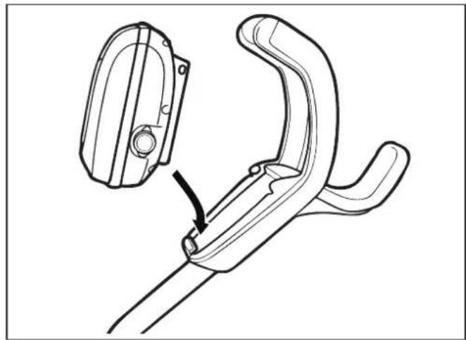
natural_image
Technical line drawing of a mechanical clamp or bracket assembly with a close-up inset showing the component (no text or symbols)Figure 10. Align Control box with Caddy Hook
- Press control box onto the caddy hook until it snaps and locks into position (Figure 11).
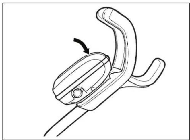
natural_image
Line drawing of a mechanical clamp or clip assembly with an arrow indicating rotation (no text or symbols present)Figure 11. Attach the Control box onto Caddy
VX40 and VX45 4WD:
-
Align the bottom of the control box with the notch in the base (see Figure 12).
-
Press control box down firmly to snap in place.
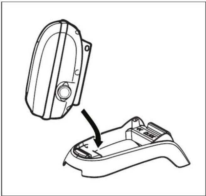
natural_image
Technical line drawing of a mechanical component with an arrow indicating assembly or adjustment (no text or symbols present)Figure 12. Attach Control box to Base
3.4 Connecting Floating Cable to Control Box
WARNING
Failure to comply with the following warnings can increase risk of fire or electrocution which can result in property damage and serious injury, including loss of life.
PREVENT ELECTRICAL SHOCK
- Keep the control box at least 3.5 m from the edge of the pool.
- The cleaner is to be installed in accordance with the relevant requirements of the Australian wiring rules AS/NZS 3000. Also refer to the installation instructions relating to the swimming pool equipment for which the cleaner will be an integral part. The cleaner is to be supplied through a Residual Current Device (RCD) with a rated residual operating current of 30mA.
- Do not use an extension cord to connect the control box.
- Do not allow anyone to swim while the cleaner is in the pool.
-
The control box is water-resistant, not waterproof. In order to prevent electrocution, never submerge the control box or leave exposed to inclement weather.
-
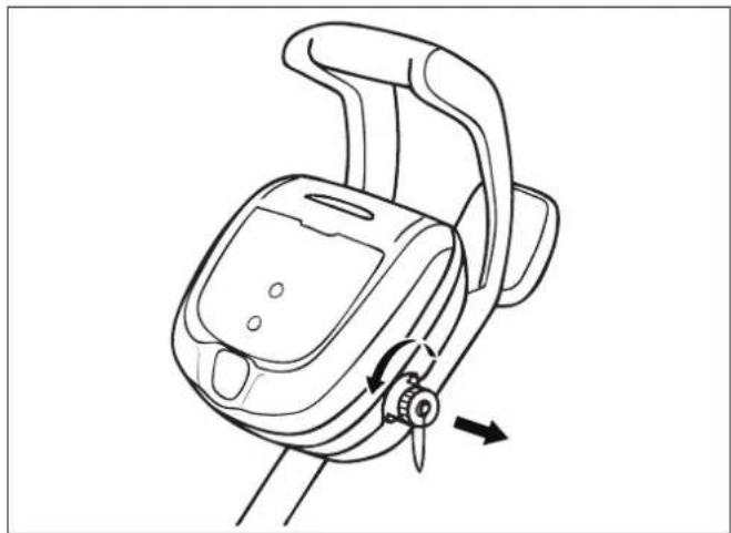
Unscrew the protective cap for the power cable from the side of the control box by turning counter-clockwise (Figure 12).
natural_image
Line drawing of a mechanical device with a handle and scroll, showing a rotational arrow (no text or symbols)Figure 13. Remove Protective Cap
natural_image
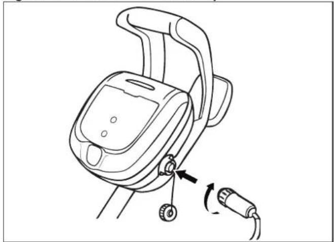
Line drawing of a handheld device with a cable and switch, showing no text or symbolsFigure 14. Connect Power Cable
- Grip the notched end of the floating power cable, insert into the control box, and turn clockwise to tighten. (Figure 14.)
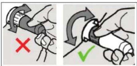
NOTE: To avoid damaging the power cable, do not try to twist the entire cable housing (see below).
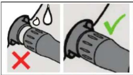
NOTE: To avoid exposing the power cable connector pins to water, be sure the connector is screwed in all the way and there is no gap. (see below).
Section 4. Operation
CAUTION
To prevent damage to the cleaner, be sure to adhere to the following guidelines:
- Remove the cleaner from the pool after the cleaning cycle is completed and store on the caddy out of direct sunlight or inclement weather.
- For VX40 and VX45 4WD models where caddy is not included in the pack, store the cleaner out of direct sunlight or inclement weather. Store the control box on the base as shown in Figure 12.
- Never lift the cleaner out of the pool by the floating cable. Always use the lift feature to remove cleaner from the pool.
• Take additional care when lifting the cleaner out of the pool. It becomes heavier when filled with water.
• Always remove the cleaner from pool when super chlorinating or adding acid. - Do not handle cleaner while it is in operation.
IMPORTANT
• Always make sure the cleaner head is fully submerged before you begin operation.
- Clean the filter canister after each cleaning cycle.
- Do not leave your cleaner in the pool on a permanent basis.
- At the end of each cycle, remove the cleaner from the pool. Start at the cleaner head and untangle any coils in the cable before storing the cleaner.
When the control box is powered on with the floating cable attached, the operating time for the current selected cycle is displayed.
The robotic cleaner includes a safety feature that automatically stops the cleaner if it is powered on but not submerged in water. For pools equipped with a beach area, this safety feature is programmed to drive the cleaner in reverse and back into the pool when the impeller is out of the water.
4.1 Submerging the Cleaner
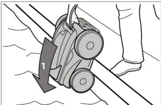
- Submerge the cleaner in the pool and remove any air trapped inside by keeping the unit vertical (Figure 15).
natural_image
Diagram of a car being pulled down on a rope, showing a downward arrow labeled '1' (no text or symbols beyond the label)Figure 15. Submerge the Cleaner Vertically
- Ensure the unit sinks to the bottom of the pool and does not float (Figure 16).
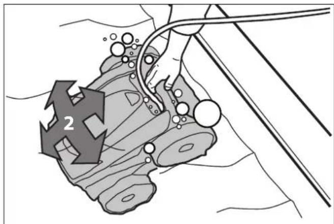
Figure 16. Cleaner Sinking to the Bottom of the Pool
- Spread out the floating cable over the pool, ensuring there are no kinks or coils in the cable.
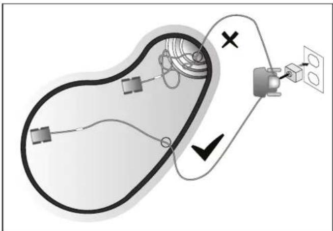
NOTE: For optimal patterning and reduced tangling, the floating cable should enter the water near the middle of the pool length. Only place enough cable in the water to reach the farthest point in the pool (see Figure 17).
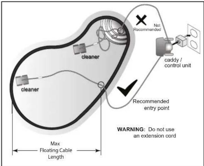
Figure 17. Setup for Optimal Patterning
4.2 The VX40 Cleaner Control box
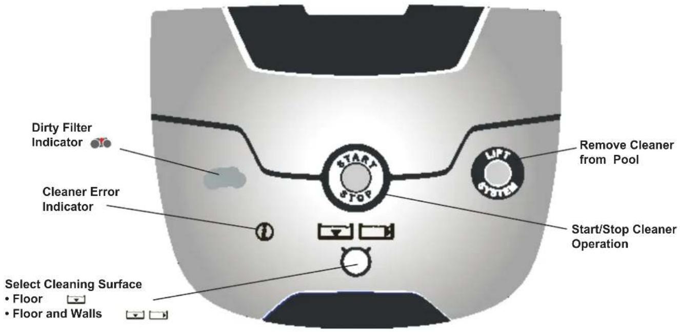
Figure 18. VX40 Control Box
4.3 The VX45 4WD and VX50 4WD Cleaner Control box
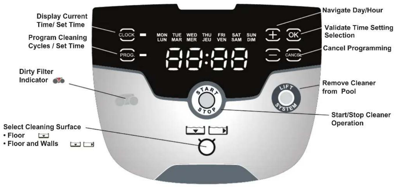
Figure 19. VX45 4WD and VX50 4WD Control Box
4.4 The VX55 4WD Cleaner Control box
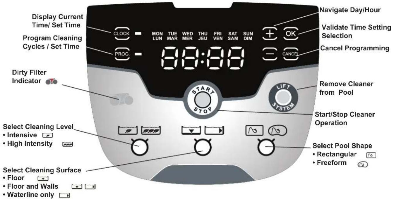
Figure 20. VX55 4WD Control Box
4.5 Starting the Cleaner
The default cleaning surface setting for the Vortex cleaners is Floor Only ▼. To change the current programmed cycle, see Section 5. Programming the Cleaner.
Select Cleaning Surface (all models):
Use ▼ ▶ to change cleaning surface setting.

Toggle between: Floor Only

Floor and Walls

Waterline (VX55 4WD only)
Select Cleaning Intensity Level (VX55 4WD only):
Use 📄 📌 📃 to choose cleaning intensity level.

Toggle between: INTENSIVE

HIGH INTENSITY
Select Pool Shape (VX55 4WD only):
Use 📄 📋 to choose pool shape.

Toggle between: RECTANGULAR

FREEFORM
Begin Cleaning:
After selecting the cleaning surface and other options as applicable, press 📋 to begin operation.
The screen displays the time remaining for the selected cycle. For example, 0:44 on the display indicates that cleaning will be completed in 44 minutes.
NOTE: The control box automatically switches to standby power mode after 10 minutes of inactivity and the display screen turns off. Press any key to exit standby mode. Cleaner will continue to function in standby mode if in the middle of a cleaning cycle.
4.6 Stopping the Cleaner and Removing from the Pool
The automated Lift System makes removing the cleaner from the pool simple. The Lift System will move the cleaner toward the edge of the pool then drive it to the surface for removal.
- At the end of the cleaning cycle, or at any time during a cleaning cycle, press LIFT to begin the automated lift procedure.
Press and hold the Lift System button to turn cleaner to the left. Cleaner will keep rotating left. Once the cleaner is oriented towards the wall of your choice, release the button.
Press and release the Lift System button and the cleaner will drive up the wall and to the waterline and wait to be retrieved.
The screen displays
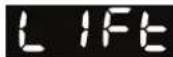
when the Lift
System is in operation.
NOTE: To stop the lift procedure at any time, press

- When the cleaner is within arm's reach, use the handle to remove from the water (Figures 21, 22). Never lift the cleaner out of the pool by the floating cable.
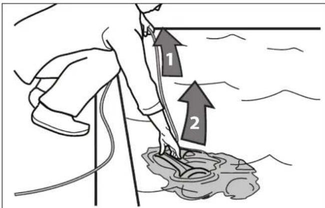
Figure 21. Remove Cleaner From Pool with Handle
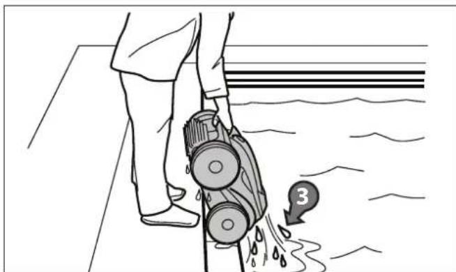
Figure 22. Keep Cleaner Vertical to Drain Water
4.7 Operating the Cleaner with the Remote Control (VX55 4WD only)
The VX55 4WD robotic cleaner comes with a handheld remote control stored on the cleaner caddy next to the control box. The remote control is factory-synchronized to your cleaner's control box.
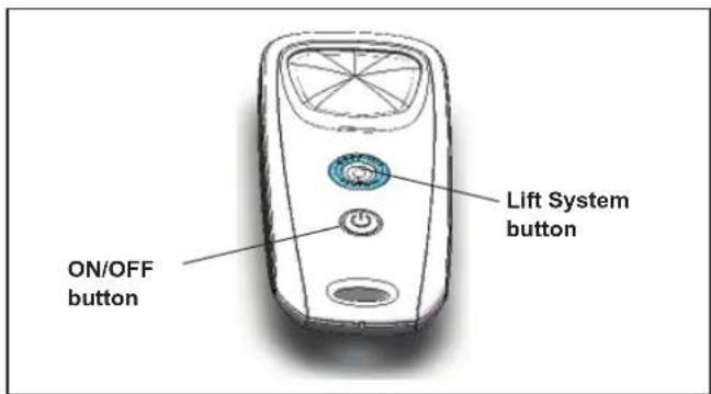
Figure 23. VX55 4WD Remote Control
• To turn on the remote control:
Press (see Figure 23) and hold for 3 seconds.
The display shows [---] to indicate the cleaner is now operating in remote control mode.
- To pilot the cleaner, point the device toward the cleaner in the water and move directionally as shown in Figure 24.
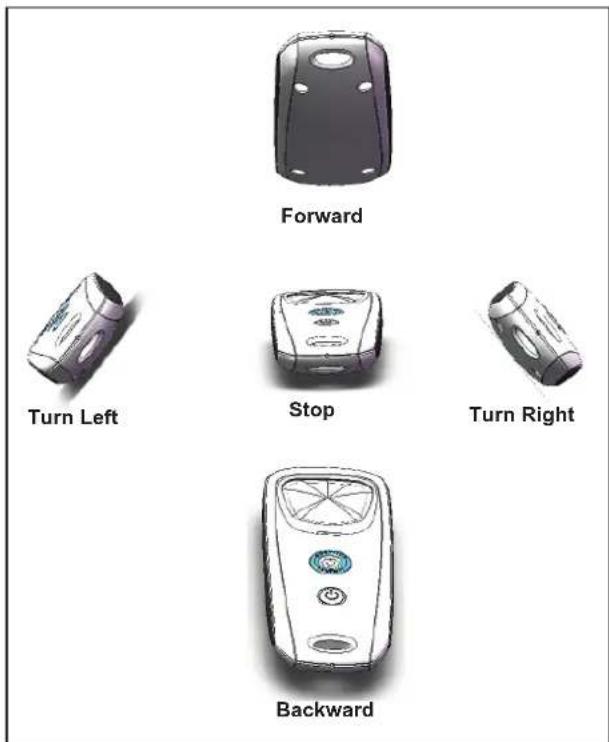
Figure 24. Remote Control Directional Commands
- To remove the cleaner from the pool using the remote control, press (see Figure 23).
The cleaner rotates left until you release the Lift System button.
4.8 Synchronizing the Remote Control
Even though the remote control is factory-synchronized to your cleaner's control box, it may be necessary to synchronize again if you need to replace either the control box or the remote control.
• To synchronize the remote control to the control box:
Press ⏻ and hold for 3 seconds to turn on remote. Plug the control box into a power source.
When the display shows the operating time, press

ultaneously for six (6) seconds.
- The display shows followed by the normal operating time display to indicate the cleaner is now synched with the remote and ready to begin operating in remote control mode.
4.9 Storing the Cleaner
The cleaner must be cleaned regularly using slightly soapy clean water. Do not use solvents such as acetone or its equivalent. Rinse the cleaner generously using clean water. Do not let your cleaner dry in direct sunlight near the pool.
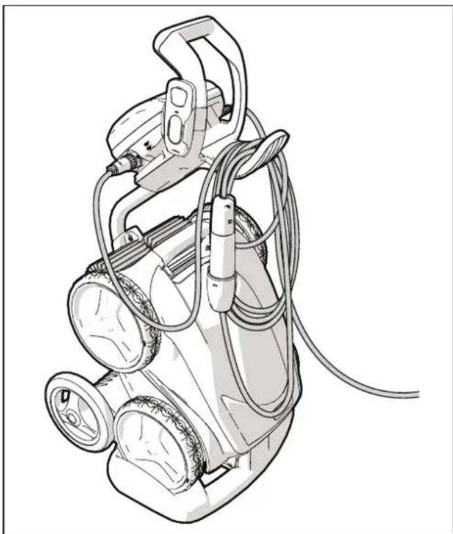
NOTE: For VX50 4WD and VX55 4WD models, it is recommended that the cleaner is stored on its caddy for drying (see Figure 26). For VX40 and VX45 4WD models where caddy is not included in the pack, store the cleaner out of direct sunlight or inclement weather. Store the control box on the base (see Figure 12).
-
Disconnect the floating cable from the control box. Replace the protective cap on the control box.
-
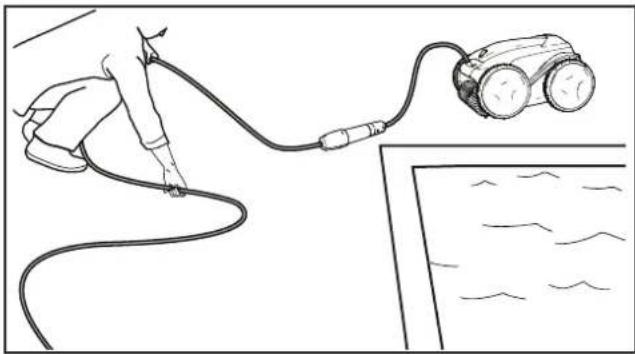
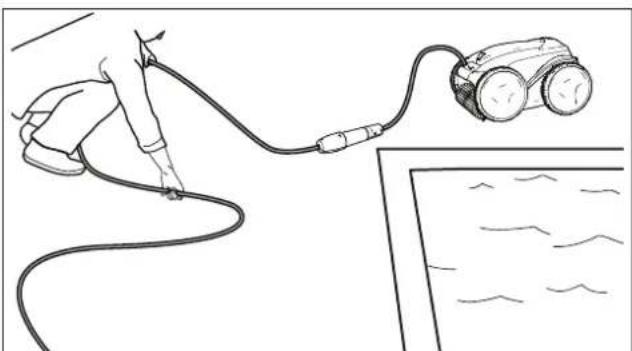
Starting at the cleaner head. Remove all coils and tangles from the floating cable (Figure 25).
natural_image
Line drawing of a robotic car connected to a cable with a hand holding the cable (no text or symbols)Figure 25. Untangle the Floating cable
- Loosely coil the floating cable starting at the cleaner and moving toward the connection point at control box.
natural_image
Line drawing of a portable air purifier with attached hoses and wheels (no text or symbols)Figure 26. Cleaner Correctly Stored on Caddy
Section 5. Programming the Cleaner
(VX45 4WD/ VX50 4WD and VX55 4WD)
The control box allows you to program the cleaner to run each day for up to 7 days, perfect for when you go away on holidays. (It is not recommended that you keep your cleaner in the pool for unnecessary periods of time when not running.)
NOTE: You cannot change programming or display current day and time during a cleaning cycle.
5.1 Displaying Current Day and Time

- Press ☐ to display current day and time in 24-hour clock format.
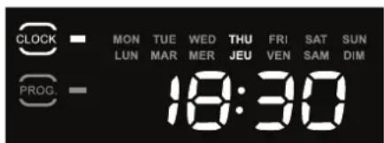
Current day and time is displayed for 5 seconds.
5.2 Changing the Clock Day and Time

- Press and hold for three seconds.
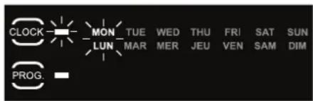
All days of the week flash twice.


- Press or buttons to cycle through seven (7) days and display desired day.

- Press to select.
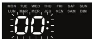
Current hour setting flashes.


- Press or buttons to cycle through 24 hours and display desired hour setting.
NOTE: Control box is set to display time in 24-hour clock format. Time setting will cycle through 1-24.

- Press to select.
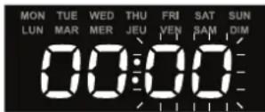
Current minutes setting flashes.


- Press or buttons to cycle through 1-59 minutes and display desired minutes setting.

- Press to select.

- Press ☐ to set time and exit the menu.

- Press ☐ to display current day and time setting and verify the time you set is correct.
5.3 Changing Default Cleaning Times
Use to change cleaning surface setting.

Default cleaning times are:

Floor Only: 1 hour 30 minutes

Floor and Walls:
2 hours 30 minutes
Waterline (VX55 4WD only):
Variable cleaning time depending on settings


- Press or buttons to increase or decrease cleaning time in 30-minute increments.

- Press to select.
5.4 Programming Cleaning Cycles
You can program up to seven cleaning cycles.
Program cleaning for either seven consecutive cycles or the same cycle repeated over several weeks
(e.g., every Wednesday and Saturday for three weeks).
- Choose pool cleaning settings to program.
All models:
Choose ▼ ▶ to select either the pool floor or the floor and walls of the pool.
VX55 4WD:
- Choose 📋 to select waterline only in addition to Floor Only or Floor and Walls.
- Choose 📄 📌 to select intensive or high intensity level cleaning.
- Choose 📄 to select pool shape.

- Press 📋 to view current programmed cleaning cycles.
Cycle day and time is displayed for three seconds.
- When the cleaning cycle you want to change
is displayed, press and hold 5 seconds.
The days of the week flash twice.
NOTE: If the display flashes all zeros, the time has not been set (new cleaner). Day and time must be set before you can program cleaning times, see section 5.2 Changing the Clock Day and Time.


- Press or steps to cycle through 7 days of the week.

- Press to select.
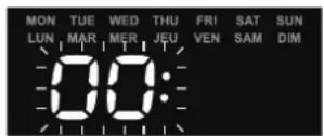
Hour setting flashes twice.


- Press or buttons to
through 24 hours.

- Press to select.
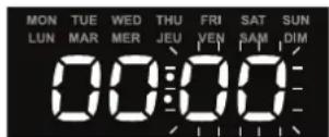
Minutes setting flashes zero.


- Press or buttons to cycle through four 15-minute increments (00, 15, 30, or 45).

- Press to select.
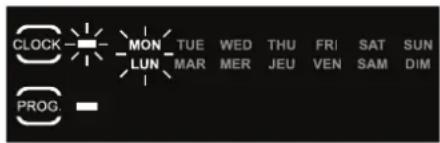
The next day to program flashes.

- Press program an additional cleaning cycle for a different day OR

Press 📁 to exit the programming menu
Days of the week are lit indicating programs stored in the control box memory for that day.
5.5 Canceling Cleaning Cycles
To Cancel an Individual Program:
- Press 🤒 and hold for 3 to 5 seconds.
The days of the week flash twice.

- Press or buttons to cycle through seven (7) days.


NOTE: If the day of the week flashes with no time displayed, there is no program set for that day.

- Press and hold for 3 to 5 seconds to delete programming for the selected day.
Press

to exit.
To Cancel All Programs:

-
Press ☐ to make sure you have exited the Programming Menu.
-
Press and hold to delete all programming in the control box.

The display will turn off for one (1) second.
When all programs are cancelled, the current day and time is displayed on the screen with no days of the week lit.
Section 6. Cleaning and Maintenance
WARNING
To avoid electric shock and other hazards which could result in permanent injury or death, disconnect (unplug) the control box from the power source before performing any cleaning and maintenance.
6.1 Cleaning the Filter Canister
The filter canister should be cleaned at the end of each cycle.
- Make sure the control box cable is disconnected from the electrical outlet or the floating cable has been disconnected from the control box.
- Remove the cleaner from the water and let the remaining water drain by maintaining the cleaner in the vertical position.
- Set the unit on its wheels.
- To remove the filter canister assembly from the cleaner, follow steps 5 through 8.
- Push the cover lock (1) and lift the cover (2) until it is secured in the vertical position. (Figure 27).
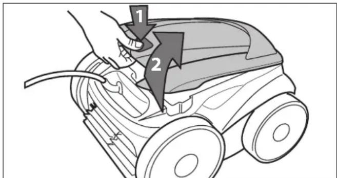
Figure 27. Lift Cleaner Cover
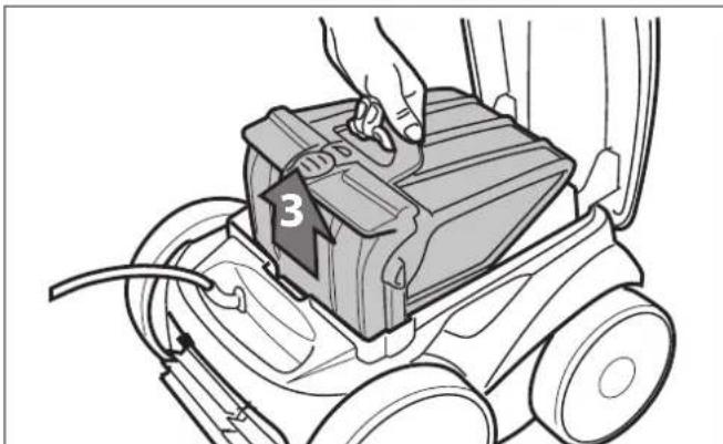
- Remove the filter canister assembly from the body (3), as shown in Figure 28.
natural_image
Line drawing of a person using a vacuum cleaner on a wheeled cart (no text or symbols)Figure 28. Remove Filter Canister Assembly
- Push the quick release button on the canister assembly (4) and pull open the filter assembly (5), as shown in Figure 29.
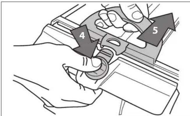
Figure 29. Open Filter Canister Assembly
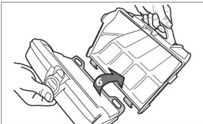
- Separate the filter canister from the filter support (6), as shown in Figure 30.
natural_image
Line drawing of hands assembling a plastic housing component with a numbered arrow indicating rotation (no text or symbols present)Figure 30. Remove Filter Canister
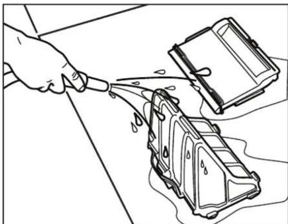
- Empty all debris from the fi lter canister, then rinse the canister, the fi lter support, and the cleaner under water or using a hose, as shown in Figure 31.
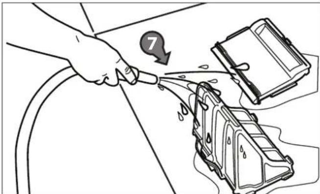
Figure 31. Wash Filter Canister
6.2. Cord Tangling
Tangling can occur more frequently when operating the cleaner on the automatic timer 7-Day Programmed Cycle (VX45 4WD/ VX50 4WD and VX55 4WD). Spread out the floating cable over the pool, ensuring there are no kinks or coils in the cable. Do not leave the cleaner unattended for prolonged periods and follow procedure below to avoid excessive tangling.
NOTE: For optimal patterning and reduced tangling, the floating cable should enter the water near the middle of the pool length. Only place enough cable in the water to reach the farthest point in the pool.
After every cleaning cycle:
natural_image
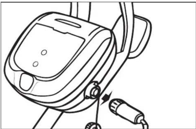
Line drawing of a mechanical device with attached cables and buttons (no text or symbols)- Unplug the floating cable at the control box.
natural_image
Line drawing of a person using a cable to connect a small robotic car (no text or symbols present)- Remove the cleaner from the pool and untangle any kinks and coils in the floating cable starting at the cleaner head.
natural_image
Line drawing of a hand pouring liquid into a water-filled device with a device on top (no text or symbols)- Remove filter canister and rinse with clean water. Plug the floating cable back into the control box and store cleaner for next use.
6.3 Replacing the Brushes
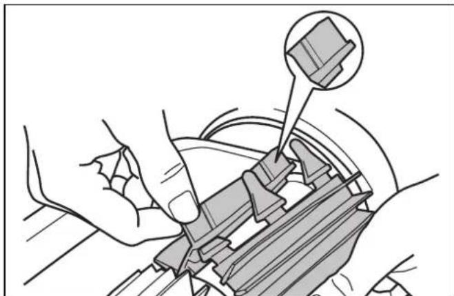
The cleaner is fitted with PVC brushes. There are "wear" indicators on the brushes (Figure 32). To maintain cleaner performance at its best you need to replace the brushes as soon as one of the wear indicators is reached (even if the blade wear is not even). It is recommended that you replace the brushes when the rubber is worn down to the top of the wear indicator (or every two years, whichever comes first).
natural_image
Mechanical assembly diagram showing hands operating a car seatbelt with a magnified inset of the component (no text or symbols)Figure 32. Wear Indicators
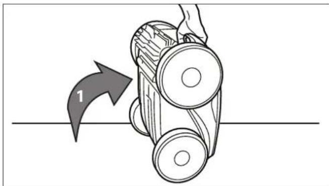
- Lift the cleaner to a vertical position so that the handle is up (Figure 33).
natural_image
Diagram of a mechanical device with a hand operating it, showing a curved arrow labeled '1' pointing to the component (no text or symbols beyond the number)Figure 33. Cleaner in Upright Position
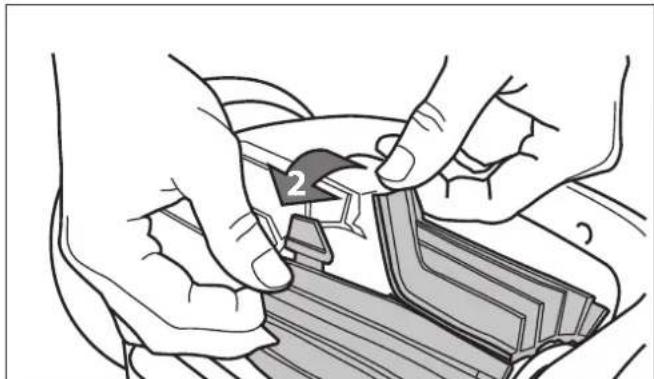
- Separate the edges of the brush and undo the tabs (Figure 34). Remove the worn brushes.
natural_image
Illustration of hands installing or adjusting a mechanical component with a numbered arrow (no text or symbols present)Figure 34. Undo the Tabs of the Brush
- To install a new brush matt, position the new brush matt on the roller with the bristles facing downwards (Figure 35).
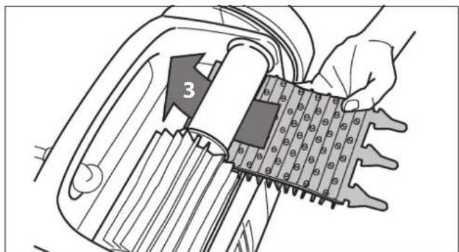
Figure 35. Install the New Brush
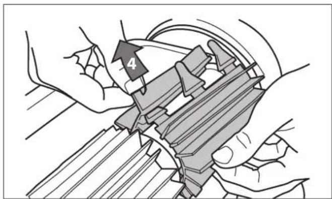
- Thread each tab into the slot provided and gently feed it through until the heel comes out at the other side of the slot (Figure 36).
natural_image
Illustration of hands assembling or adjusting a mechanical component with a numbered arrow (no text or symbols present)Figure 36. Pull Tabs Through Each Slot
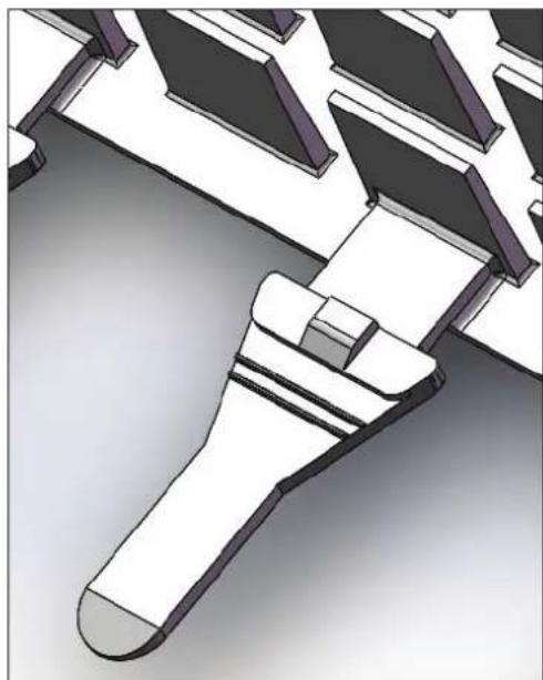
- Use scissors to cut the tabs at the guides, as shown in Figure 37.
natural_image
3D CAD model of a mechanical component with no visible text or symbolsFigure 37. Cut Tabs
- Repeat this procedure to replace the second brush matt.
6.4 Replacing the Tyres
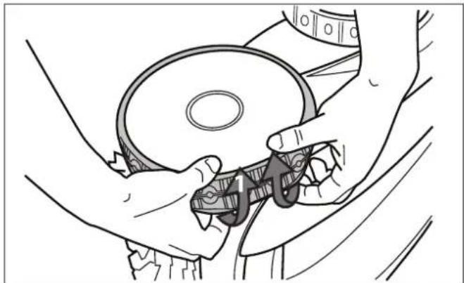
- Pull on the inside of the old tyre to remove the tyre lip from the wheel (Figure 38).
natural_image
Line drawing of hands operating a CD or DVD disc with a clip (no text or symbols)Figure 38. Pull the Old Tyre Over the Wheel
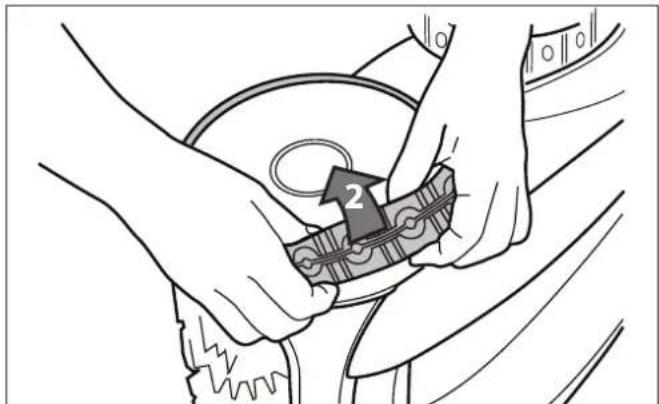
- Remove the old tyre (Figure 39).
natural_image
Illustration of hands assembling a mechanical component with a numbered arrow (no text or symbols)Figure 39. Remove the Old Tyre
- To replace the tyre, position the tyre on the wheel making sure to orient the tyre so that the word INSIDE is toward the body of the cleaner (Figure 40).
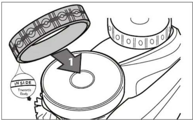
Figure 40. Tyre Replacement Orientation
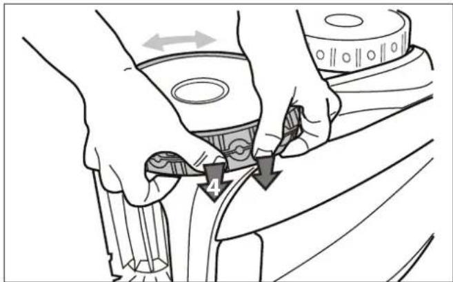
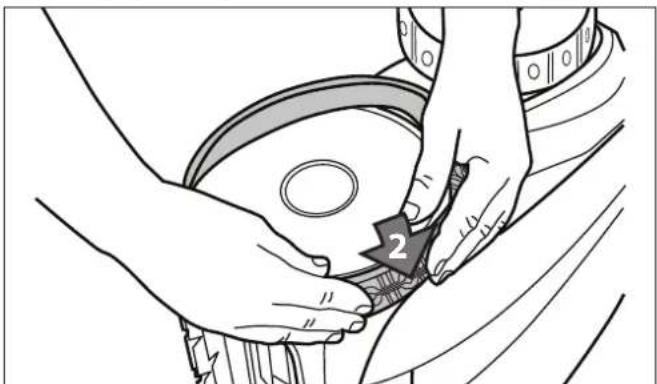
- Push one side of the tyre on to the wheel and fit the rib of the tyre in the groove of the wheel (Figure 41).
natural_image
Line drawing of hands adjusting a mechanical component with arrows indicating motion (no text or symbols)Figure 43. Push the Tyre into Place on the Wheel
natural_image
Illustration of hands cleaning a car wheel rim with a numbered label (2), no text or symbols present.Figure 41. Start on One Side of the Tyre
- Work the tyre onto the wheel and verify the rib of the tyre is positioned properly within the groove of the wheel (Figure 42).
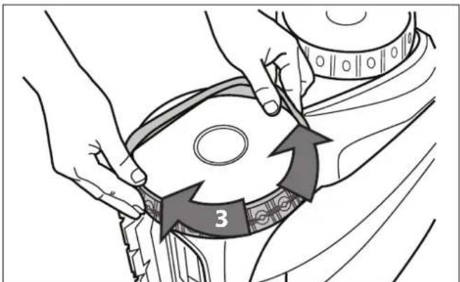
Figure 42. Work the Tyre On Around the Wheel
- Push and position the rib of the inner side of the tyre in the groove of the wheel (Figure 43B). If needed, turn the wheel gently to help with installation.
Section 7. Troubleshooting
7.1 Using the Information LED for Troubleshooting (VX40 Cleaner)
The Information LED ⓘ on the control box flashes in a specific sequence to indicate one of three possible cleaner malfunctions.
| Information LED Flashing Solution | |
| LED flashes once with one second interval. | Unplug the floating cable from the control box and reconnect.If the problem is not resolved through troubleshooting, contact Zodiac After Sales Support at 1300 763 021. |
| LED flashes twice with one second interval | Turn cleaner wheels to ensure they are not jammed.Check brushes for debris.Start a new cleaning cycle.If the problem persists, contact Zodiac After Sales Support at 1300 763 021. |
| LED flashes three times with one second interval | Check propeller for debris.Clean the filter.Start a new cleaning cycle.If the problem persists, contact Zodiac After Sales Support at 1300 763 021. |
7.2 Viewing Cleaner Status Information for Troubleshooting (VX45 4WD, VX50 4WD, and VX55 4WD)
Information about your cleaner's current status and any relevant error condition is available through a troubleshooting status screen. After cycling through each message, control box returns to current day and time display. To view cleaner status information:
-
Remove cleaner from the pool and turn power off.
-
Press and at the same time and hold for at least five (5) seconds.
The following cleaner operation messages are displayed consecutively for three (3) seconds:
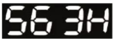
Total hours cleaner has run since new.
Zodiac recommends no more than 3 x cleaning cycles per week or to maintain a clean pool and keep the filter less clogged.
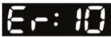
Last error code (if cleaner has had at least one error).
Time (in operating hours) the error occurred.
7.3 General Troubleshooting
The following table lists some of the common symptoms, causes, and solutions for correcting cleaner operation problems.
| Problem Cause Solution | ||
| The flashing indicator lights (VX40) or error code (VX45 4WD, VX50 4WD and VX55 4WD) appear just after start. NOTE: If flashing lights are accompanied by an error code on the display, refer to Control box Error Codes. | Floating cable may not be plugged into the control box correctly. | Unplug floating cable from the control box and reconnect. |
| Cleaner may not be fully submerged. | Remove cleaner from the pool and re-submerge, see Submerging the Cleaner. | |
| Cleaner may need to be reset and begin a new cycle. | Turn control box power OFF, then back ON, then restart the cleaner. | |
| Propeller may be jammed and not turning correctly. | Contact Zodiac After Sales Support at 1300 763 021. | |
| Wheels may be jammed and not turning correctly. | Contact Zodiac After Sales Support at 1300 763 021. | |
| The flashing lights appear during the cleaning cycle. | Cleaner may be sucking air (lights will appear after 60 seconds air intake) | Remove cleaner from the pool and re-submerge, see Submerging the Cleaner. |
| The cleaner does not stay firmly on the pool bottom. | There is air in the appliance casing. | Submerge the cleaner following the procedure in Submerging the Cleaner. |
| The filter canister is full or dirty. Clean | the filter canister, see Cleaning the Filter Canister. | |
| The cleaner does not or no longer climbs the pool sides. | The filter canister is full or dirty. Clean | the filter canister, see Cleaning the Filter Canister. |
| Sides of pool are slippery or slimy. Although the water seems clear, microscopic algae, invisible to the human eye, are present in the pool. As a result the pool sides become slippery and prevent the cleaner from climbing. Check tyres for wear and replace as necessary. | Do a shock chlorination treatment. DO NOT leave the cleaner in the pool during this treatment. | |
| On startup the cleaner does not move. | Not supplied with electricity. The outlet, the control box is connected to, is not supplying electrical power. Check that the outlet to which the control box is connected is receiving electricity. | |
| Unit is turned ON. Check that you have started one (1) of the two (2) programs and check that the indicator for the selected program is lit. If the indicator light is not lit, turn the wheels then disconnect the control box and wait at least 20 seconds before reconnecting. If the problem persists, contact Zodiac After Sales Support at 1300 763 021. | ||
| Cable is tangling in the pool | Too much cable length in the water. Do not unravel the entyre cable length. Place only the required length of cable in the water and place the rest on the side of the pool. Follow the procedure in Cord Tangling to avoid and correct tangled cord. | |
| The cleaner is not cleaning effectively. | The brushes have become smooth or the "wear" indicator shows. | Replace the brushes following the procedure in Replacing the Brushes. |
| Filter canister is full or dirty. Clean the filter canister following the procedure in Cleaning the Filter Canister. | ||
| Floating cable is excessively coiled or kinked. | Make sure the floating cable is spread out over the pool. Ensure the cable is not too tightly wrapped or coiled when storing. If the problem persists, lay the cable straight in the sun to relax it and remove kinks. | |
7.4 Control Box Error Codes (VX45 4WD, VX50 4WD and VX55 4WD)
The control box will display one of ten different error codes to indicate specific problems with either the control box or mechanically with the cleaner.
- To remove an error code after troubleshooting, press any key and the control box turns off.
- If an error code is displayed and no key pressed, the screen goes into standby mode after 10 minutes of inactivity.
Press any key to turn the screen back on.

- When an error is detected, programming for the control box is temporarily suspended. The
turned off.
Press and hold the

button to clear the error code and reactivate current programming.
| Error Code Cause • Solution | ||
| 1 | (1) Pump short-circuit. | • Check for any small debris or floating cable stopping brushes from turning freely. |
| 2 | (2) Right side traction motor short-circuit | • Check the connector pins in the floating cable for corrosion or a bent pin. |
| 3 | (3) Left side traction motor short-circuit | • Turn each wheel one quarter turn in one direction repeatedly until rotation is smooth and not catching, then repeat turning wheel in the opposite direction until rotation is smooth.• If problem is not resolved through troubleshooting, contact Zodiac After Sales Support at 1300 763 021. |
| 4 | Pump motor overconsumption • Check for small debris or hair in the fan.• Clean the filter canister. | |
| 5 | (5) Right side drive motors overconsumption | • Check for any small debris or hair and that the floating cable is not caught, stopping brushes from turning freely. |
| 6 | (6) Left side drive motors overconsumption | • Turn each wheel one quarter turn in one direction repeatedly until rotation is smooth and not catching, then repeat turning wheel in the opposite direction until rotation is smooth. |
| 7 | (7) Cleaner floats on the surface. | • Turn cleaner power off, then submerge cleaner according to correct procedure. |
| 8 | (8) Cleaner is turned on and running out of water. | |
| 9 | NOT A CLEANER ERROR • End of cycle status code. Cleaner function is normal. No action required. | |
| 10 | Cleaner and control box communication error. | • Turn cleaner power off then back on to restart the program.• Check connection of the floating cable on the control box.• Check the connector pins in the floating cable for corrosion or a bent pin.• If problem is not resolved through troubleshooting, contact Zodiac After Sales Support at 1300 763 021. |
Section 9. Conformity

The manufacturer reserves the right to modify these specifications without notice. Although the robotic pool cleaners have been tested in a large variety of swimming pools, Zodiac cannot guarantee that this robotic pool cleaner will be compatible with all pools. Some pool features may affect performance. For further advice, please contact your Zodiac dealer.
Zodiac Group Australia Pty Ltd.
PO Box 7238
Wetherill Park NSW 2164, Australia
1300 763 021 | www.zodiac.com.au
- WARNING
- Table of Contents
- Section 1. Important Safety Instructions......3
- Section 2. Cleaner Specifications ....4
- Section 3. Assembly......4
- Section 4. Operation......8
- Section 5. Programming the Cleaner .... 14
- Section 6. Cleaning and Maintenance ..... 16
- Section 7. Troubleshooting ...... 21
- Section 1. Important Safety Instructions
- READ AND FOLLOW ALL INSTRUCTIONS
- PREVENT ELECTRICAL SHOCK
- PREVENT CHILD INJURY AND DROWNING
- CAUTION
- SAVE THESE INSTRUCTIONS
- Section 2. Cleaner Specifications
- General Specifications
- Section 3. Assembly
- Unpacking
- Assembling the Transport Caddy (VX50 4WD and VX55 4WD)
- Connecting the Control box to Caddy (VX50 4WD / VX55 4WD) or Base (VX40 / VX45 4WD)
- VX50 4WD / VX55 4WD:
- VX40 and VX45 4WD:
- Connecting Floating Cable to Control Box
- Section 4. Operation
- IMPORTANT
- Submerging the Cleaner
- The VX55 4WD Cleaner Control box
- Starting the Cleaner
- Select Cleaning Surface (all models):
- Select Cleaning Intensity Level (VX55 4WD only):
- Select Pool Shape (VX55 4WD only):
- Begin Cleaning:
- Stopping the Cleaner and Removing from the Pool
- Operating the Cleaner with the Remote Control (VX55 4WD only)
- Synchronizing the Remote Control
- Storing the Cleaner
- Section 5. Programming the Cleaner
- (VX45 4WD/ VX50 4WD and VX55 4WD)
- Displaying Current Day and Time
- Changing the Clock Day and Time
- Changing Default Cleaning Times
- Programming Cleaning Cycles
- All models:
- VX55 4WD:
- Canceling Cleaning Cycles
- To Cancel an Individual Program:
- To Cancel All Programs:
- Section 6. Cleaning and Maintenance
- Cleaning the Filter Canister
- Cord Tangling
- After every cleaning cycle:
- Replacing the Brushes
- Replacing the Tyres
- Section 7. Troubleshooting
- Using the Information LED for Troubleshooting (VX40 Cleaner)
- Viewing Cleaner Status Information for Troubleshooting (VX45 4WD, VX50 4WD, and VX55 4WD)
- General Troubleshooting
- Control Box Error Codes (VX45 4WD, VX50 4WD and VX55 4WD)
- Section 9. Conformity
Brand : ZODIAC
Model : VX45
Category : Vacuum Cleaner