IQGH604W - Cooker ElectriQ - Free user manual and instructions
Find the device manual for free IQGH604W ElectriQ in PDF.


| Product Type | Freestanding Cooker |
| Brand | ElectriQ |
| Model | IQGH604W |
| Color | White |
| Height | 900 mm |
| Width | 600 mm |
| Depth | 600 mm |
| Net Weight | Approx. 50 kg |
| Power Supply | 230 V ~ 50 Hz |
| Total Power Consumption | 10 kW (gas hob) / 2.4 kW (electric oven) |
| Hob Type | Gas – 4 burners |
| Burner Ignition | Automatic electronic ignition |
| Flame Failure Safety Device | Yes – on all burners |
| Oven Type | Electric fan oven |
| Oven Capacity | 65 liters |
| Oven Functions | Convection, grill, bottom heat, defrost |
| Cleaning Aid | Enamel interior – easy clean |
| Oven Door | Removable inner glass for cleaning |
| Child Lock | Yes |
| Timer | Yes – with alarm |
| Energy Class (Oven) | A (estimated) |
| Spare Parts Availability | Burner caps, grates, knobs, oven heating elements available from ElectriQ or third parties |
| Repairability Index | 8/10 (based on typical freestanding cooker design) |
| Included Accessories | Oven shelf, grill pan, burner pan supports, instruction manual |
Frequently Asked Questions - IQGH604W ElectriQ
User questions about IQGH604W ElectriQ
0 question about this device. Answer the ones you know or ask your own.
Ask a new question about this device
Download the instructions for your Cooker in PDF format for free! Find your manual IQGH604W - ElectriQ and take your electronic device back in hand. On this page are published all the documents necessary for the use of your device. IQGH604W by ElectriQ.
USER MANUAL IQGH604W ElectriQ
Service Manual For Built-in gas hob

Warnings:
- This service manual is not available to the general users, but only applies to professional technicians with relevant qualifications. Any incorrect maintenance may result in other dangers!
● The power and gas supply must be cut off before maintenance! - A new power cord which meets the relevant technical requirements must be used once possible hidden malfunctions are found with the current power cord (refer to this Manual)!
- Please read carefully all safety warnings in this Manual before maintenance!
- The product is prohibited from using until test is conducted as per relevant regulations after maintenance!
- This service manual applies to many models, so the specific operations please prevail in kind!
Catalogue
1. Precaution 4
1.1. Safety Precauon ....4
1.2. Warning....4
2. Description of the appliance .... 5
2.1. Features....5
2.2. Components and parts....6
3. Installation 7
3.1. Dimension....7
3.2.Installaon Dimension....8
4. Electric Diagram 9
5. Reassembly and Disassembly.... 10
5.1. Safety precautions....11
5.2. Tools .... 11
5.3 Disassembly....12
5.3.1. Disassemble the Top Plate .... 12
5.3.2. Disassemble the Thermocouple....13
5.3.3. Disassemble of the Ignion Pin....13
5.3.4. Disassemble of the Microswitch Harness ....13
5.3.5. Disassemble of the Gas Pipe ....14
5.3.6. Disassemble of the Boom Cup....14
5.3.7. Disassemble of the Power Cord Assembly 14
5.3.8. Disassemble of the igniter....15
5.3.9. Disassemble of the Valve & Manifold Pipe Assembly....15
5.310. Disasmble of the Gas Connecon ....16
5.3.11. Disassemble of theboom plate....16
5.4. Reassembly....17
5.4.1. Reassemble of the Ignion Pin....17
5.4.2. Reassemble of the Thermocouple....17
5.4.3. Reassemble of the Gas Pipe....17
5.4.4. Check Point after assemble....17
6. Troubleshooting.... 17
6.1. Troubleshoong ....18
6.2. Problems and Corrective Measures ......19
6.3. Maintenance and test ....21
7. Gas Conversion.... 22
7.1. Replacement of gas-type ng....22
7.2. Replacement of the injector of the burners....22
- Appendix.... 24
Technical & quality requirements for Built-in gas hob....24
1. Precaution
1.1. Safety Precaution
- Do not modify this appliance. This appliance should be serviced by an authorized person.
- All repairs should be done in accordance with the procedures described in this manual.
- Before you begin, turn off the gas and electricity supply to the appliance. Remove remaining gas in product completely by igniting burner.
- Be sure that all of built-in protective devices are replaced. Restore any missing protective shields.
- Do not connect the gas and electricity supply before replacement complete.
- Use replacement components that have the same ratings. A replacement part that does not have the same safety characteristics as the original might create shock, fire or other hazards
- You must conduct a gas leakage test after receiving after-sales service in gas pipe and gas connector. Never touch any circuit wiring with your hand nor with uninsulated tool during operation.
1.2. Warning

- The power cord shall be replaced with the original power cord, specifications for an insulation power line which is no less than AWG8*2 +AWG10*1 and resists temperature of greater than 60°C.
- All apparatus within a radius of 50mm from this product must resist temperature of greater than 75^ C, otherwise, deformations are easily to be caused during the application process of this product.
- When the wrapping materials are removed, keep such materials like metal sheet, packing bag, foam and screws out of reach of children's reach to avoid potential dangers. For example, the children may suffocate as a result of swallowing tiny components or playing with packing bag.
2. Description of the appliance
2.1. Features
Glass: □□* □□0 ( □□□□* ; ;
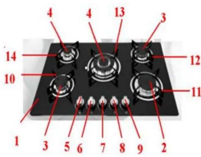
1, top plate
2, rapid burner
3, semi-rapid burner
4, auxiliary burner.
5, control knob for lower left burner
6, control knob for upper left burner
7, control knob for middle burner.
8, control knob for upper right burner
9, control knob for lower burner
10, pan support lower left.
11, pan support lower right.
12, pan support upper right.
13, pan support middle
14, pan support upper left
Stainless: □□* □□0 ( □□□□6; ;
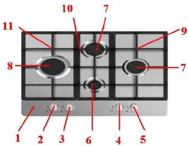
1, top plate.
2, control knob for left burner
3, control knob for upper burner.
4, control knob for lower burner
5, control knob for right burner
6, auxiliary burner
7, semi-rapid burner
8, rapid burner
9, pan support right
10, pan support middle
11, pan support left
2.2. Components and parts
(1). Burner
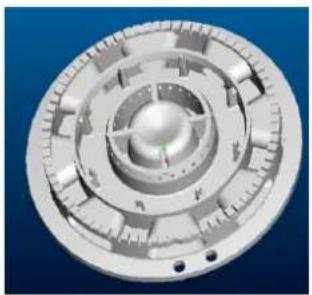
natural_image
3D rendered mechanical component with concentric rings and mounting holes (no text or symbols visible)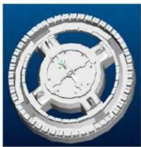
natural_image
Close-up of a mechanical gear or cam mechanism with no visible text or symbols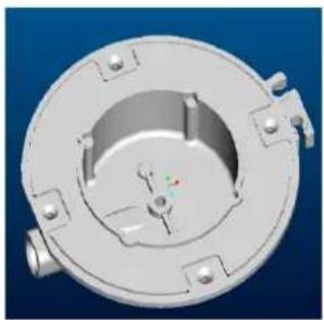
natural_image
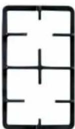
3D rendered mechanical component with circular housing and mounting flanges (no text or symbols visible)(2).Pan support
natural_image
Pure geometric grid pattern with intersecting lines and dots, no text or symbols present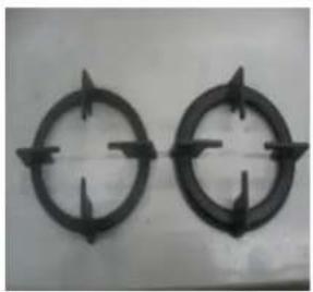
natural_image
Two identical circular mechanical components with directional arrows, mounted on a plain surface (no text or symbols)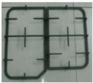
natural_image
Two identical rectangular metal frames with vertical centerlines, placed on a tiled surface (no text or symbols visible)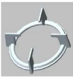
natural_image
Abstract circular diagram with three arrows pointing outward from a central ring (no text or symbols)(3). Knob
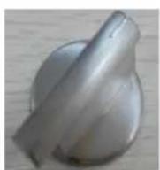
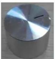
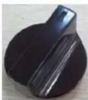

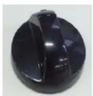
(4).Drip tray
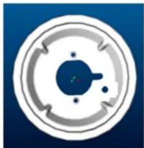
natural_image
Circular diagram with concentric rings and a central blue dot, no text or symbols present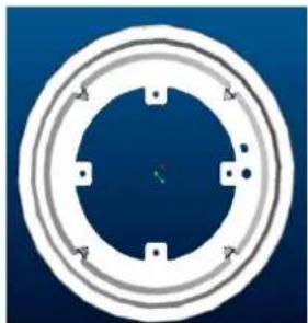
natural_image
Circular mechanical component with concentric rings and mounting holes, set against a blue background (no text or symbols)3. Installation
3.1. Dimension
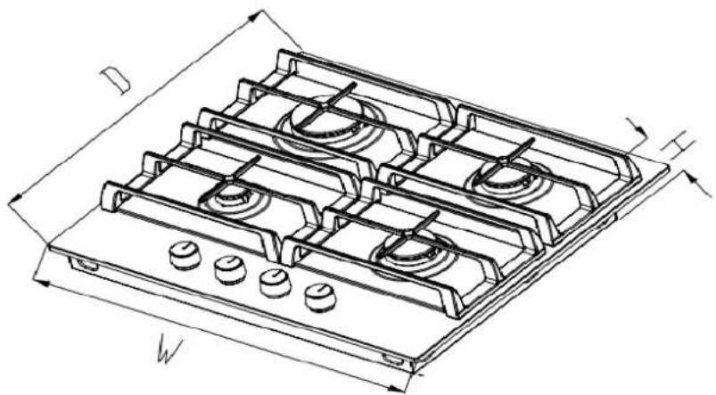
natural_image
Technical line drawing of a gas stove with six panes and mounting holes (no text or symbols)| Model | W (mm) | H (mm) | D (mm) |
| 60Gxxxxxxxx- xxx | 600 | 110 | 510 |
| 70Gxxxxxxxx- xxx | 705 | 110 | 510 |
| 75G50xxxxxx- xxx | 750 | 90 | 510 |
| 90Gxxxxxxxx- xxx | 860 | 100 | 520 |
Note: Dimensions for reference only
3.2. Installation Dimension
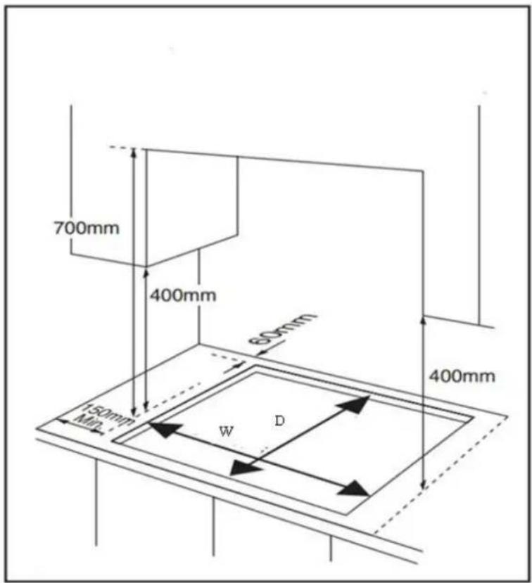
Cut out size:
| Model | W(mm) | D (mm) | T(mm) |
| 60Gxxxx08x- xxx | 553 | 473 | 30(min) |
| 60Gxxxx4xx- xxx | 553 | 473 | 30(min) |
| 60Gxxxx006- xxx | 580 | 490 | 30(min) |
| 60Gxxxxxxxx- xxx | 560 | 490 | 30(min) |
| 70Gxxxxxxxx- xxx | 560 | 490 | 30(min) |
| 75G50xxxxx- xxx | 730 | 490 | 30(min) |
| 90Gxxxxxxxx xxx | 850 | 490 | 30(min) |
Note: Dimensions for reference only
This appliance is to be built into a kitchen unit or worktop of right size, providing the following minimum distances are allowed;
- The edge of the appliance must be a minimum distance of 55mm from a rear wall.
– A minimum distance of 150mm must be left between the side edges of the appliance and any adjacent cabinets or walls.
- The minimum distance combustible material can be fitted above the appliance in line with the edges of the appliance is 400mm .
- The minimum distance combustible material can be fitted directly above the appliance is 700mm.
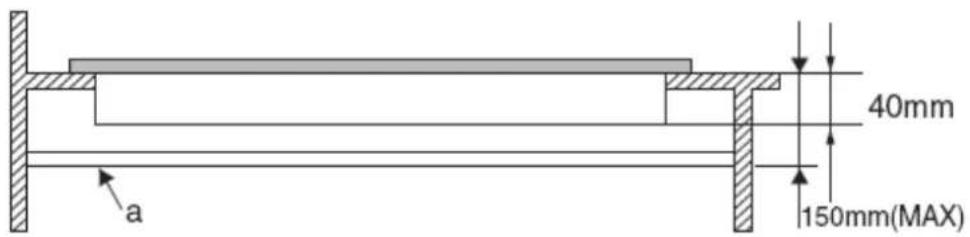
-This panel (a) must be positioned at a maximum distance of 150mm below the worktop. Gas pipe or connector shouldn't be bent or blocked by any other appliances
- You must conduct a gas leakage test after installation over gas connection and gas pipe.
- An oven must have forced ventilation to install a hob above it.
– Check the dimensions of the oven in the installation manual.
- The cut out size must obey the indication.
- Electric Diagram
a. Four burners model
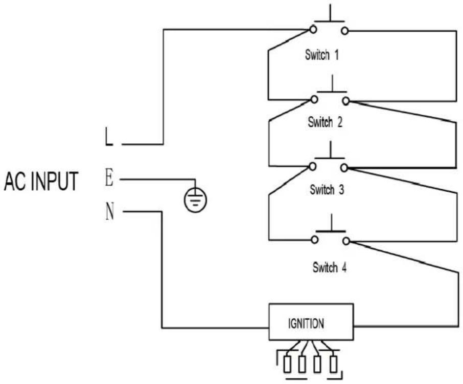
flowchart
graph TD
    A["AC INPUT"] --> B["L"]
    A --> C["E"]
    A --> D["N"]
    B --> E["Switch 1"]
    C --> F["Switch 2"]
    D --> G["Switch 3"]
    E --> H["Switch 4"]
    F --> I["Switch 4"]
    G --> J["Switch 4"]
    H --> K["IGNITION"]
    I --> K
    J --> K
    K --> L["Ground"]
b. Five burners model
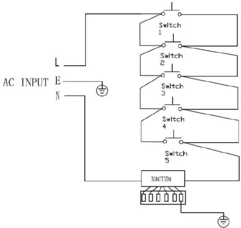
5. Reassembly and Disassembly
5.1. Safety precautions

WARNING
Turn off power for safety and appliance protection.
Close middle valve to prevent gas leakage
Keep away from inflammable materials around appliance.
Before work, put on gloves.

CAUTION
Cool off the appliance for a while right after using appliance for your safety because you can get burners by high temperature from the appliances.
5.2. Tools
Most of the tools that you might need are shown below. Some are optional.
| Item | How to use | Pictures |
| Screw driver | Use for assembly and disassembly of all screws | 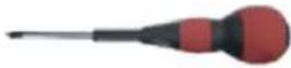 |
| Tubing Wrench | Use for assembly and disassembly of tubing to the burner cup | 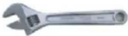 |
| 7mm Vox Driver | Use for assembly and disassembly of injector nozzles. |  |
| 7mm spanner | Use for assembly and disassembly of injector nozzles. (Triple burner) |  |
5.3 Disassembly
5.3.1. Disassemble the Top Plate
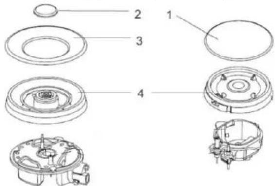
Step 1: Remove parts on the Top Plate
a. Remove parts on the top plate: Burner lids, Flame spreaders, Control handles
b. When disassembling, keep parts safe, do not drop them to the appliance.
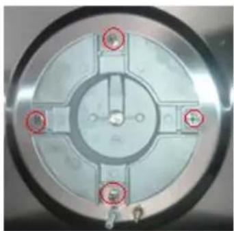
Step 2: Disassemble of Screws on the Top Plate
a. Remove the screws of the burner
b. In some versions, remove screws on the side of bottom plate.
c. Be careful in order not to damage screw heads when disassembling.
d. Be careful not to damage the top plate.
natural_image
Close-up of a circular mechanical component with four red-circled features and central hub (no visible text or symbols)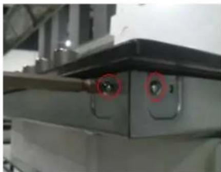
natural_image
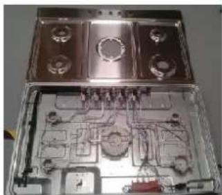
Close-up of a mechanical device with two circular red markers highlighting features (no visible text or symbols)Step 3: Detachment of the Top Plate
a. Separate the top plate.(In case of stainless steel model, take off the sponge.)
b. During assembly, be careful in order not to give physical impact on parts such as ignition devices, flame supervision devises..
natural_image
Interior view of an open industrial or mechanical housing with multiple compartments and internal components (no visible text or symbols)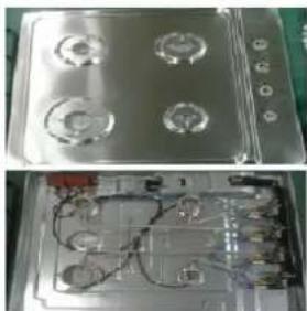
natural_image
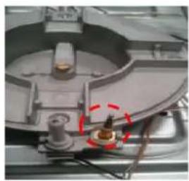
Two views of a metallic appliance with four circular components and internal wiring (no visible text or symbols)5.3.2. Disassemble the Thermocouple
Step 1: Unscrew the nut out.
Step 2: Pull the silver terminal of Thermocouple
Step 3: When reassembling, replace parts correctly
natural_image
Close-up of a mechanical component with a red circular annotation highlighting a specific part (no visible text or symbols)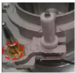
natural_image
Close-up of a mechanical component with a red circular annotation highlighting a yellow object (no visible text or symbols)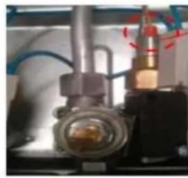
natural_image
Close-up of a mechanical valve assembly with no visible text or symbolssilver terminal
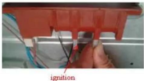
5.3.3. Disassemble of the Ignition Pin
Step 1: Pull the washer and take off ignition pin
Step 2: Pull the housing of Ignition pin out of the igniter.
Step 3: When reassembling, replace parts correctly.

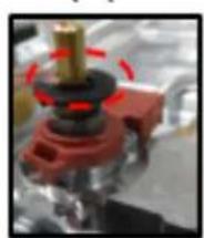
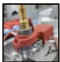
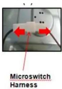
5.3.4. Disassemble of the Microswitch Harness
Step 1: Before you disassemble the harness, take off the plastic e-ring.
Step 2: When you take off the micro switch harness, please be careful not to break the hook.
Step 3: When you reassemble the harness, replace it correctly.
Step 4: Detach the wire from the power cord assembly harness.
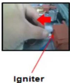
Step 5: Hold housing of the wire by hand and pull it out of the igniter
natural_image
Close-up of a mechanical assembly with red and black components, no visible text or symbolse - ring
natural_image
Close-up of a red mechanical component with a golden tool inserted, no visible text or symbolsHook
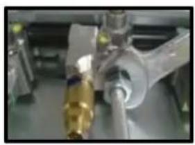
5.3.5. Disassemble of the Gas Pipe
Step 1: Unscrew the nuts out. at both ends of the pipes
Step 2: Pull the pipes
natural_image
Close-up of mechanical components with no visible text or symbols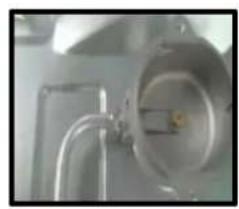
natural_image
Close-up of a metallic industrial pipe fitting with a circular component (no visible text or symbols)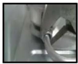
natural_image
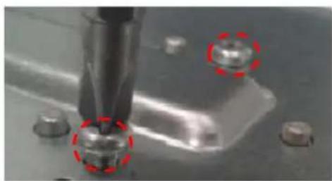
Close-up of a metallic mechanical component with a curved handle (no visible text or symbols)5.3.6. Disassemble of the Bottom Cup
Step 1: Remove all screws on the bottom cup
Step 2: Detach the bottom cup from the base box burner
natural_image
Close-up of a precision tool tip interacting with small metallic components, marked by red dashed circles (no visible text or symbols)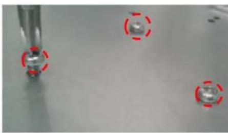
natural_image
Close-up of a metallic tool with four small metallic components and red dashed circles highlighting features (no text or symbols)5.3.7. Disassemble of the Power Cord Assembly
Step 1. Detach the wire from the Microswitch Harness.
Step 2. Hold housing of the wire by hand and pull it out of the igniter.
Step 3. For power cord grounding, you must use grounding screw attached with washer.
Step 4. Remove 2 screws and detach the power cord ass'y set
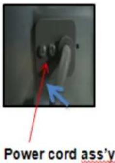
5.3.8. Disassemble of the igniter
Step1. Remove 2 screws
Step2. Detach the igniter from the base box burner.
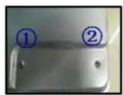
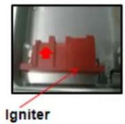
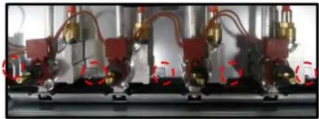
5.3.9. Disassemble of the Valve & Manifold Pipe Assembly
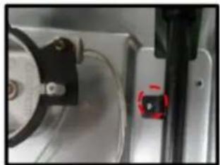
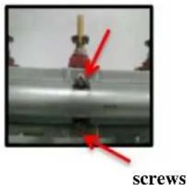
Step 1. Remove 5 screws
Step 2. Remove the screw to take off pipe assy.
Step 3. Remove 2 screws and detach the valve from the manifold pipe assembly
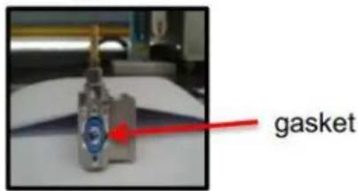
Step 4. You must check the gasket when you disassemble or assemble.
Step 5. If you have faulty one, replace it with new one.
Step 6. Conduct a leakage test after reassembling.
(a)
natural_image
Close-up of industrial machinery components with red and gold fittings, no visible text or symbols(b)
natural_image
Close-up of a mechanical component with a red circular mark and a black bracket, no visible text or symbols.(c)
natural_image
Close-up of a mechanical component with red arrows pointing to features, labeled 'screws' at bottom (no other text or symbols)(d)
5.3.10. Disasmble of the Gas Connection
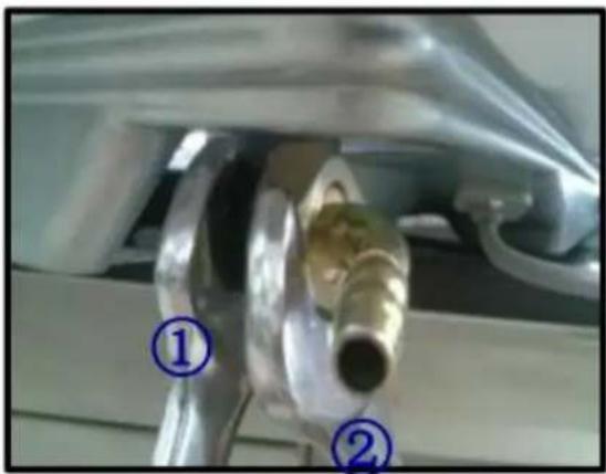
Step 1. When you disassemble/assemble gas connection, use 2 spanners. One for fixing gas connection elbow, the other for tightening gas hose.
Step 2. Tighten enough to prevent gas leakage.
Step 3. Once you're done, conduct leakage test
natural_image
Close-up of a mechanical component with two numbered callouts (① and ②) indicating parts of a pipe fitting or valve assembly.5.3.11. Disassemble of the bottom plate
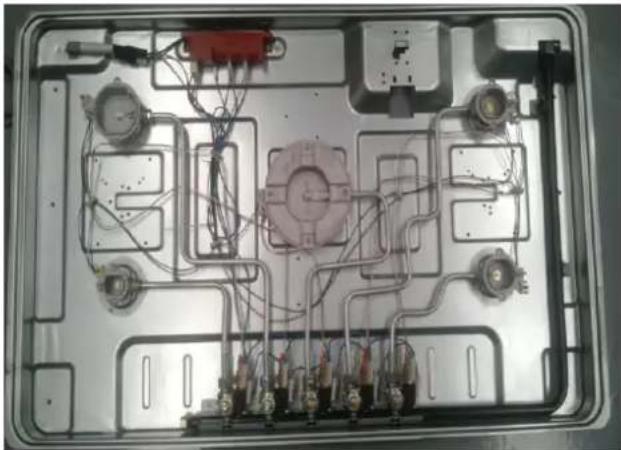
Step 1. Separate casing on sink.
Step 2. Detach the appliance as checking the status of the gas connection and the power cord assembly set.
natural_image
Interior view of an electronic device casing with wiring and connectors (no visible text or symbols)5.4. Reassembly
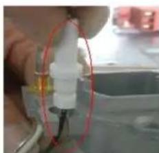
5.4.1. Reassemble of the Ignition Pin
Step 1. Pull the line of the ignition pin in to the hole on bottom cup along the gap on bottom cup
Step 2. Push ignition pin to adjust the position
Step 3. Klemm ignition pin with snap spring to fox the ignition pin.
natural_image
Close-up of a hand holding a white plastic component with a red circular outline, no visible text or symbols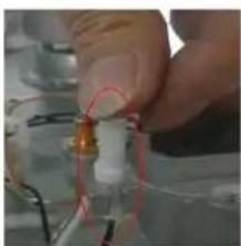
natural_image
Close-up of a hand holding a small electronic component with red circular annotations (no visible text or symbols)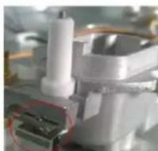
natural_image
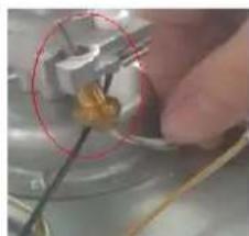
Close-up of a mechanical assembly with a white cylindrical component and red circular detail (no visible text or symbols)5.4.2. Reassemble of the Thermocouple
Step 1. Insert thermocouple into the relevant hole of the bottom cup from bottom to top. Step 2. Adjust position of the thermocouple in the hole of the bottom cup. Step 3. screw up the nut to fix the thermocouple.
natural_image
Close-up of a hand holding a small object with wires, no visible text or symbols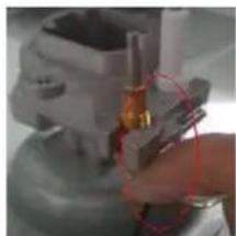
natural_image
Close-up of a mechanical component with a red circular annotation highlighting a section (no visible text or symbols)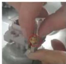
natural_image
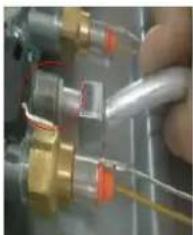
Close-up of hands assembling a small mechanical component (no visible text or symbols)5.4.3. Reassemble of the Gas Pipe
Step 1. Insert the head of the gas pipe into installation parts of the bottom cup or the valve Step 2. Screw up the nut of the joint with spanner
natural_image
Close-up of a mechanical assembly with copper and gold components, no visible text or symbols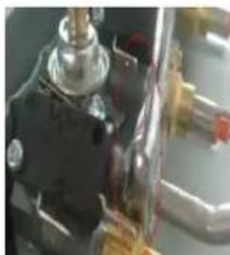
natural_image
Close-up of a mechanical component with metallic parts and wiring (no visible text or symbols)5.4.4. Check Point after assembly
a. At completion of the appliance repair, assemble after removing tools inside of the appliance.
b. You must conduct a leakage test after repairing.(refer to the leakage test on 5.3)
c. If ignition does not work, repeat ignition several times so that you can remove remaining air in the gas connection
d. Check combustion status by conducting aging
6. Troubleshooting
6.1. Troubleshooting
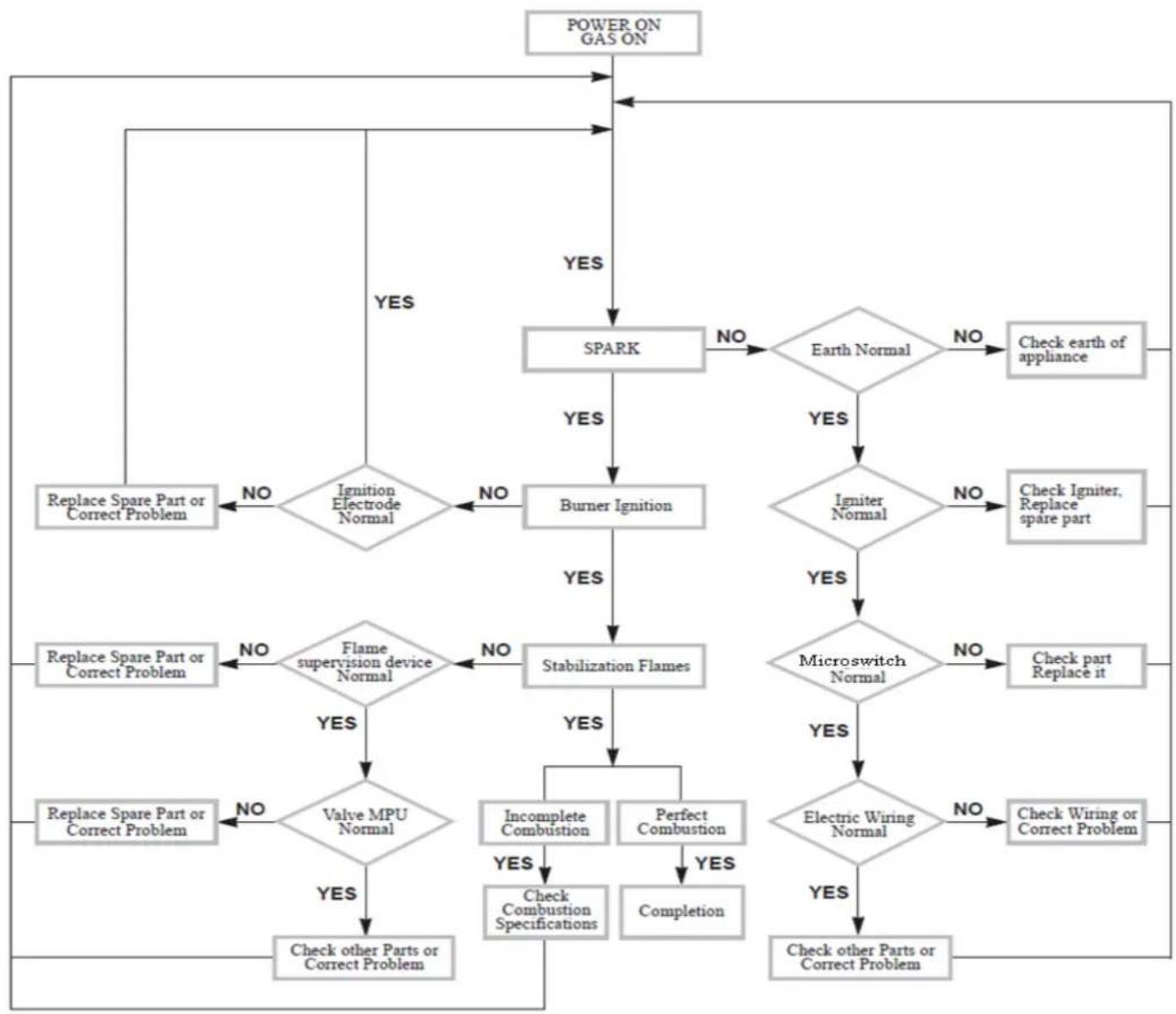
flowchart
graph TD
    A["POWER ON GAS ON"] --> B{SPARK}
    B -->|YES| C["Earth Normal"]
    B -->|NO| D["Replace Spare Part or Correct Problem"]
    B -->|YES| E["Burner Ignition"]
    E --> F{Igniter Normal}
    F -->|YES| G["Microswitch Normal"]
    F -->|NO| H["Check Igniter, Replace spare part"]
    F -->|NO| I["Replace Spare Part or Correct Problem"]
    E -->|YES| J["Stabilization Flames"]
    J --> K{Valve MPU Normal}
    K -->|YES| L["Complete Combustion"]
    K -->|NO| M["Replace Spare Part or Correct Problem"]
    K -->|NO| N["Check other Parts or Correct Problem"]
    K -->|YES| O["Perfect Combustion"]
    O --> P["Check Combustion Specifications"]
    O -->|YES| Q["Completion"]
    O -->|YES| R["Electric Wiring Normal"]
    R --> S["Check Wiring or Correct Problem"]
    R -->|NO| T["Check other Parts or Correct Problem"]
    B -->|NO| U{Ignition Electrode Normal}
    U -->|YES| V["Fire suppression device Normal"]
    U -->|NO| W["Replace Spare Part or Correct Problem"]
    V --> X{Stabilization Flames}
    X -->|YES| Y["Incomplete Combustion"]
    X -->|NO| Z["Replace Spare Part or Correct Problem"]
6.2. Problems and Corrective Measures
| Problem | Symptom | Probable cause | Solution |
| Ignition | Not ignited | The ignition Electrode is badly assembled | Assemble the Ignition Electrode correctly |
| No Spark | Assemble the micro switch correctly | ||
| Put a plug into the outlet | |||
| Check the power code and the Ignition Electrode are connected with igniter correctly | |||
| The Ignition Electrode is peeled off | Insulate the Ignition Electrode with a rubber tube or tap | ||
| The middle valve is closed | Open the middle valve completely | ||
| The igniter is faulty | Replace igniter by a new one after checking above solutions | ||
| Remaining air in the gas connection | Repeat ignition several times | ||
| Badly ignited | Nozzle hole is clogged | Clean the nozzle | |
| The Ignition Electrode is wet | Dry the Ignition Electrode carefully | ||
| The burner lid is badly assembled | Assemble the lid correctly | ||
| The Ignition Electrode is contaminated with alien substance | Wipe such alien substance with dried clothing | ||
| The Ignition Electrode Body is broken | Replace the Ignition Electrode by a new one | ||
| The burners are wet | Dry the burner lids carefully | ||
| The hole in the flame spreader are clogged | Clean the flame spreader | ||
| Ignition Incomplete combustion | Fire off as soon as you release the control knob | The flame supervision device is badly assembled | Connect the flame supervision device with the valve correctly |
| Connect the flame supervision device with the burner correctly | |||
| Flames go out | There are draughts near the appliance | Avoid any severe draughts ih the room | |
| Fire off while using | The flame supervision device is contaminated with alien substance | Clean or replace the flame supervise device | |
| Gas is not supplied | Check if the gas cylinder is empty | ||
| The valve MPU is faulty | Replace the valve by a new one | ||
| The sealing rings have come out of correct place | Assemble the sealing ring correctly | ||
| Incomplete combustion | Noise made when combusted and ignited | The burner lid is badly assembled | Assemble the burner lid correctly |
| Yellow Flame | The holes in the flame spreader are clogged | Clean the flame spreader | |
| Different gas is used | Check the gas used | ||
| Unstable Flame | The burner lid is badly assembled | Assemble the burner lid correctly | |
| Different injector is used | Use the injector corresponding to the gas | ||
| Gas supply is poor | Check you have enough gas | ||
| Lifting | The burner lid is badly assembled | Assemble the burner lid correctly | |
| The gas pressure is too high | Adjust it to the normal pressure | ||
| Back burn | The gas pressure is too low | Adjust it to the normal pressure | |
| Different gas is used | Check the gas used | ||
| Gas leakage | Gas smell | A gas tap has been left on | Check to see if any gas taps are on |
| There may be a leak between the coupling and the gas bottle | Make sure that the connection is airtight | ||
| A Tube is reassembled without 0-ring | Be careful not to damage or loss of 0-ring | ||
| The valve is connected badly with Main gas tube | Assemble correctly | ||
| Any gas connection part(tube, Main gas tube, etc)are broken | Replace the broken part by a new one |
Note!
1 Check the ground wire before the fault is detected;
2 Enough attention must be given to high voltage circuit.
6.3. Maintenance and test
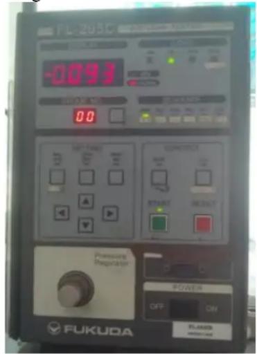
Air leakage test
Tool: Air leakage device, soapy water
- Professional repair procedures
a) Connect product to the air leakage device and set the test pressure at 15kPa;
b) The plug valve shall be kept closed and the gas pipelines may be tested its leakage through air leakage device;
c) All plug valves shall be kept open, block the injectors at the burner, the flame-out protection valve shall be kept open and the gas pipelines may be tested their leakage through air leakage device.
The maximum leakage must be controlled below 0.5mL/min as required in the test.
- Simple procedures:
a) Connect the product to the gas source being used;
b) Smear soapy water at each joint of the product gas pipelines, the plug valve is kept closed, check visually each joint for air bubbles;
c) Smear soapy water at each joint of product gas pipelines, all plug valves shall be kept open, block the injectors at the burner, the flame-out protection device valve shall be kept open and check visually for any air bubbles.
No air bubbles shall be detected at each joint as required in the test.
Note: Any component of the product gas pipelines shall not be disassembled or replaced only if the air leakage is proved in conformity with relevant requirements.
7. Gas Conversion
All work must be carried out by a qualified technician,
Before you begin, turn off the gas and electricity supply to the appliance.
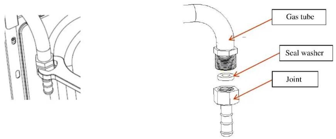
7.1. Replacement of gas-type itting
Tool: Open-end wrench
Steps for operation:
a) Disassemble with a wrench the gas-type fittings from main gas tube.
b) Lock tightly a replaceable gas-type fitting onto the main gas tube.
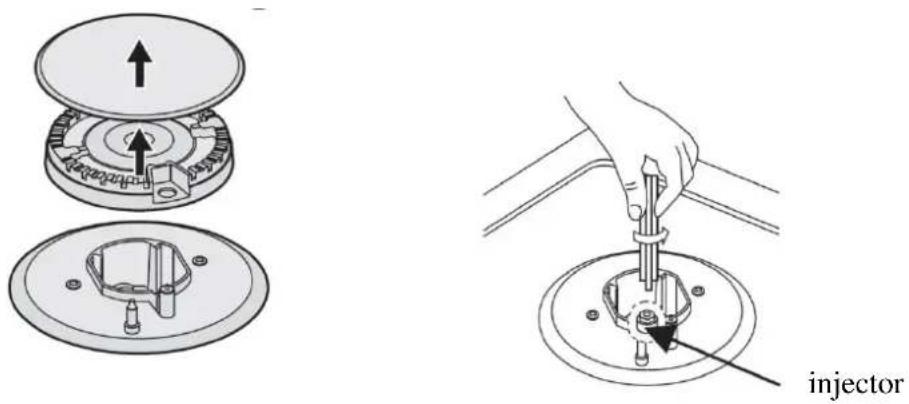
7.2. Replacement of the injector of the burners
Tool: 7mm box spanner
Steps for operation:
Step 1: Remove the pan support, burner lid and flame spreader.
Step 2: Unscrew the injector with a 7 mm box spanner and replace it with the stipulated injector for new gas supply.(see the following table)
Step 3: Carefully reassemble all the components.
After injectors are replaced ,it is advisable to tighten the injector in place. strongly.
Comparison list for injector replacement
Nominal heat input and rates see below at 15°C at 1013mbar
| COUNTRY | TYPE OF GAS | BURNER | Triple-Crown(SABAF 3.6kW) | Triple-Crown(SBT 3.3kW) | Rapid(3.0kW) | Semi-rapid(1.75kW) | Auxiliary(1.0kW) | |||||
| POSITION | Max | Min | Max | Min | Max | Min | Max | Min | Max | Min | ||
| GB, IT, FR,HU, BE, LT,NL, PT, ES,CZ, SK, RU、KZ, UKR | G30 BUTANE29 mbar | Injector make(1/100mm) | 96 | 93 | 85 | 65 | 50 | |||||
| Nominal heat input(kW) (Hs) | 3.60 | 2.10 | 3.30 | 2.10 | 3.00 | 1.00 | 1.75 | 0.65 | 1.00 | 0.41 | ||
| Nominal flow rstes(g/h) | 253 | 147 | 232 | 147 | 211 | 70 | 120 | 45 | 71 | 29 | ||
| GB, IT, FR,HU, BE, LT,NL, PT, ES,CZ, SK | G31 PROPANE37 mbar | Injector make(1/100mm) | 96 | 93 | 85 | 65 | 50 | |||||
| Nominal heat input(kW) (Hs) | 3.60 | 2.10 | 3.30 | 2.10 | 3.00 | 1.00 | 1.75 | 0.65 | 1.00 | 0.41. | ||
| Nominal flow rstes(g/h) | 240 | 140 | 221 | 140 | 199 | 66 | 118 | 44 | 68 | 27 | ||
| DE, NL | G30 BUTANE50 mbar | Injector make(1/100mm) | 76 | 76 | 75 | 58 | 43 | |||||
| Nominal heat input(kW) (Hs) | 3.60 | 2.10 | 3.30 | 2.10 | 3.00 | 1.00 | 1.75 | 0.65 | 1.00 | 0.41 | ||
| Nominal flow rstes(g/h) | 253 | 147 | 232 | 147 | 21I | 70 | 120 | 45 | 71 | 29 | ||
| GB, IT, FR,HU, BE, LT,NL, PT, ES,CZ, SK, DE,PL, NL | G20 NATURAL20 mbar | Injector make(1/100mm) | 130 | 128 | 130 | 97 | 72 | |||||
| Nominal heat input(kW) (Hs) | 3.60 | 2.10 | 3.30 | 2.10 | 3.00 | 1.00 | 1.75 | 0.65 | 1.00 | 0.41 | ||
| Nominal flow rstes(g/h) | 342 | 199 | 313 | 199 | 271 | 90 | 166 | 62 | 91 | 39 | ||
| NL | G25 NATURAL25 mbar | Injector make(1/100mm) | 140 | 140 | 122 | 95 | 70 | |||||
| Nominal heat input(kW) (Hs) | 3.60 | 2.10 | 3.30 | 2.10 | 3.00 | 1.00 | 1.75 | 0.65 | 1.00 | 0.41 | ||
| Nominal flow rstes(g/h) | 398 | 232 | 366 | 232 | 332 | 110 | 193 | 72 | 110 | 45 | ||
注:
GB: United Kingdom PT: Portugal
IT : Italy ES: Spain
FR: France CZ: Czech Republic
HU: Hungary SK: Slovakia
BE: Belgium DE: Germany
LT: Lithuania PL: Poland
NL: Netherlands RU: Russian
UKR: Ukraine KZ: Kazakhstan
TR: Turkish
8. Appendix
Technical & quality requirements for Built-in gas hob
a) Use of natural gas burner when the burner works 10 minutes in rated power, turn it to little fire and keep 60 seconds, reduce the gas pressure to 1400pa, the fire shouldn't extinct.
b) Neither flame off nor back burning should appear when the flame is in the fire hole of burner.
c) There should be no cracks and graze in the glass components and china components, besides the fringe of them.
d) In Rated gas\rated gas pressure, ignite the burner, test the time from ignition to burner working stably, it should not be more than 5 seconds.
e) In Rated gas\rated gas pressure, after the burner working for 15 minutes, turn off the plug valve, then test the time during turning off plug valve and flame-out protection device shutting down, it should be less than 90 seconds.
f) Every burner should be test ignition, fuse transferring time\ flame stabilization, ignition\ fuse transferring time should be less than 5 seconds. Flame-out will be allowed in 5 seconds after ignition, but flame should be stable in 1 minute.
g) If it may cause security problems after corrosion, electric current and other mental parts should be corrosion resistance under the normal conditions of use. Live parts and heat insulator should be prevented to contact with each other unless the heat insulator is corrosion resistance, non-hygroscopic and flame-retardant.
h) The shaft of Knob, handle ,control stick and other similar parts should be electrically neutral unless the shaft is out of the reach when the other parts are taken down.
i) The clamp device of ground terminal should be tight enough to avoid accidental loosening. The wire length from power cord block terminal or cord fixing device to block terminal should be appropriate. If the flexible cord slips off from the cord block terminal, current carrying conductor should tighten firstly compared with earth conductor.
j) Phenomenon that may reflect cooking appliance performance should not appear of the pan support in normal use.
k) Gas tightness should be accord with standard request after the gas connection was disassembled five times.
- Service Manual For Built-in gas hob
- Warnings:
- Catalogue
- Precaution 4
- Description of the appliance .... 5
- Installation 7
- Reassembly and Disassembly.... 10
- Reassembly....17
- Troubleshooting.... 17
- Gas Conversion.... 22
- Precaution
- Safety Precaution
- Warning
- Description of the appliance
- Features
- Components and parts
- Installation
- Dimension
- Installation Dimension
- Reassembly and Disassembly
- Safety precautions
- WARNING
- CAUTION
- Tools
- Disassembly
- Disassemble the Top Plate
- Step 1: Remove parts on the Top Plate
- Step 2: Disassemble of Screws on the Top Plate
- Step 3: Detachment of the Top Plate
- Disassemble the Thermocouple
- Disassemble of the Ignition Pin
- Disassemble of the Microswitch Harness
- Disassemble of the Gas Pipe
- Disassemble of the Bottom Cup
- Disassemble of the Power Cord Assembly
- Disassemble of the igniter
- Disassemble of the Valve & Manifold Pipe Assembly
- Disasmble of the Gas Connection
- Disassemble of the bottom plate
- Reassembly
- Reassemble of the Ignition Pin
- Reassemble of the Thermocouple
- Reassemble of the Gas Pipe
- Check Point after assembly
- Troubleshooting
- Troubleshooting
- Note!
- Maintenance and test
- Air leakage test
- Gas Conversion
- Replacement of gas-type itting
- Replacement of the injector of the burners
- Appendix
- Technical & quality requirements for Built-in gas hob
Brand : ElectriQ
Model : IQGH604W
Category : Cooker