
Redbox RB-UL2 - Audio Amplifier Sonifex - Free user manual and instructions
Find the device manual for free Redbox RB-UL2 Sonifex in PDF.


| Product Type | Dual Stereo Unbalanced to Balanced Converter |
| Model | Sonifex Redbox RB-UL2 |
| Number of Channels | 2 stereo (4 inputs & 4 outputs) |
| Input Connectors | 4 x RCA phono (unbalanced) |
| Output Connectors | 4 x XLR 3-pin male (balanced) |
| Input Impedance | >10 kΩ |
| Output Impedance | <50 Ω |
| Maximum Input Level | +28 dBu |
| Maximum Output Level | +28 dBu |
| Gain Range | -15 dBu to +15 dBu (ref -15 dBu into unbalanced input) |
| Frequency Response | 20 Hz to 20 kHz ±0.1 dB (600 Ω load, ref 1 kHz) |
| Total Harmonic Distortion (THD) | 0.01% @ 1 kHz, ref +8 dBu output |
| Noise | -100 dB unity gain, ref +8 dBu output |
| Common Mode Rejection (CMRR) | >66 dB typical |
| Power Supply | Filtered IEC, 110-120V or 220-240V switchable, fused, 6W max |
| Dimensions (Raw) | 28 cm (W) x 10.8 cm (D) x 4.2 cm (H) (1U) |
| Weight (Net) | 1.05 kg |
| Weight (Gross) | 1.5 kg |
| Rack Mount Kit | Optional RB-RK1 (front) or RB-RK2 (rear) |
| Front Panel LED | Power indicator |
Frequently Asked Questions - Redbox RB-UL2 Sonifex
User questions about Redbox RB-UL2 Sonifex
0 question about this device. Answer the ones you know or ask your own.
Ask a new question about this device
Download the instructions for your Audio Amplifier in PDF format for free! Find your manual Redbox RB-UL2 - Sonifex and take your electronic device back in hand. On this page are published all the documents necessary for the use of your device. Redbox RB-UL2 by Sonifex.
USER MANUAL Redbox RB-UL2 Sonifex
Analogue Redbox User Handbook
RB-MA1 Single microphone amplifier
RB-MA2 Dual microphone amplifier
RB-SM1 Single stereo to mono converter
RB-SM2 Dual stereo to mono converter
RB-UL1 Single unbalanced to balanced converter
RB-UL2 Dual unbalanced to balanced converter
RB-UL4 Quad unbalanced to balanced converter
RB-LU4 Quad balanced to balanced converter
RB-BL2 Single stereo bi-directional matching converter
RB-BL4 Dual stereo bi-directional matching converter
RB-SL2 Twin mono, or stereo, limiter
RB-DA6 6 way stereo distribution amplifier
RB-HD1 Stereo headphone amplifier
RB-HD6 6 way stereo headphone distribution amplifier
RB-SD1 Silence detection unit
RB-PMX4 10 input, 4 output preset mixer
RB-LI2 Stereo line isolation unit
RB-PLI6 6 way mono passive line isolation unit
RB-SS10 10 way stereo source selector/mixer
RB-LC3 3 way light/power controller
Revision 1.92 June, 2004
©Sonifex Ltd, 2000-4.
All Rights Reserved
Sonifex Ltd, 61, Station Road, Irthlingborough, Northants, NN9 5QE, England.
Tel : +44 (0)1933 650 700
Fax : +44 (0)1933 650 726
Email : sales@sonifex.co.uk or technical.support@sonifex.co.uk
Web : http://www.sonifex.co.uk
Information in this document is subject to change without notice and does not represent a commitment on the part of Sonifex Ltd. Sonifex Ltd shall not be liable for any loss or damage whatsoever arising from the use of information or any error contained in this manual.
No part of this manual may be reproduced or transmitted in any form or by any means, electronic or mechanical, including photocopying, recording, or information storage and retrieval systems, for any purpose other than the purchaser's personal use, without the express written permission of Sonifex Ltd.
Unless otherwise noted, all names of companies, products and persons contained herein are part of a completely fictitious adaptation and are designed solely to document the use of Sonifex products.
Contents
Warranty, Safety & Installation Information...... i
Warranty Information ......i
Returning the Warranty Card ...... ii
Safety of Mains Operated Redbox Equipment .... iii
Preparing the Machine for Use .... iii
Equipment Safety...... iii
Voltage Setting Checks.... iii
Fuse Rating ....iii
Power Cable and Connection .... iii
Ordering the Correct Mains Lead......iv
Installation Information......iv
Atmosphere iv
Electromagnetic Radiation....iv
Fitting Redboxes......v
1. RB-MA1 Single & RB-MA2 Dual Microphone Amplifiers 1-1
1.1. Introduction....1-1
1.2. System Block Diagram....1-2
1.3. Rear Panel Connections and Operation 1-2
1.3.1. Mic Inputs....1-3
1.3.2. Input Gain....1-3
1.3.3. Using Phantom Powered Microphones....1-3
1.3.4. Using the LF Filter 1-3
1.3.5. Output....1-3
1.4. Technical Specifications 1-4
1.4.1. Audio Specifications....1-4
1.4.2. Connections....1-4
1.4.3. Equipment Type....1-4
1.4.4. Physical Specifications....1-4
2. RB-SM1 Single & RB-SM2 Dual Stereo To Mono Converter 2-1
2.1. Introduction....2-1
2.2. System Block Diagram....2-2
2.3. Rear Panel Connections and Operation 2-2
2.3.1. Stereo Inputs 1 (& 2)......2-3
2.3.2. Mono Output 1 (& 2)....2-3
2.3.3. Output Gain....2-3
2.4. Technical Specifications 2-4
2.4.1. Audio Specifications....2-4
2.4.2. Connections ......2-4
2.4.3. Equipment Type....2-4
2.4.4. Physical Specifications 2-4
3. RB-UL1 Single, RB-UL2 Dual & RB-UL4 Quad Stereo Unbalanced To Balanced Converters 3-1
3.1 Introduction....3-1
3.2 System Block Diagram 3-2
3.3 Rear Panel Connections and Operation....3-2
3.3.1. RCA Phono Inputs (Left and Right) 3-3
3.3.2. Outputs (Left and Right) 3-3
3.3.3. Output Level Adjustment....3-3
3.4 Technical Specifications 3-4
3.4.1. Audio Specifications....3-4
3.4.2.Connections 3-4
3.4.3. Equipment Type....3-4
3.4.4. Physical Specifications 3-4
4. RB-LU4 Quad Stereo Balanced To Unbalanced Converter 4-1
4.1. Introduction....4-1
4.2. System Block Diagram 4-2
4.3. Rear Panel Connections and Operation....4-3
4.3.1. Inputs 1-4 (Left and Right) 4-3
4.3.2. RCA Phono Outputs 1-4 (Left and Right) ...... 4-3
4.3.3. Output Level Adjustment 4-3
4.4. Technical Specifications 4-4
4.4.1. Audio Specifications 4-4
4.4.2. Connections....4-4
4.4.3. Equipment Type 4-4
4.4.4. Physical Specifications 4-4
5. RB-BL2 Single & RB-BL4 Dual Bi-Directional Matching Converter 5-1
5.1. Introduction....5-1
5.2. System Block Diagram 5-2
5.3. Rear Panel Connections and Operation 5-3
5.3.1. Balanced to Unbalanced Connections .....5-4
5.3.2. Unbalanced to Balanced Connections .....5-4
5.4. Technical Specifications 5-5
5.4.1. Audio Specifications....5-5
5.4.2. Connections 5-5
5.4.3. Equipment Type....5-5
5.4.4. Physical Specification 5-5
6. RB-SL2 Twin Mono, or Stereo, Limiter 6-1
6.1. Introduction....6-1
6.2. System Block Diagram....6-2
6.3. Rear Panel Connections and Operation 6-3
6.3.1. Outputs 6-3
6.3.2. Inputs 6-3
6.3.3. Gain 6-3
6.3.4. Mode....6-3
6.4. Technical Specifications 6-4
6.4.1. Audio Specifications....6-4
6.4.2.Connections....6-4
6.4.3. Equipment Type....6-4
6.4.4. Physical Specifications....6-4
7. RB-DA6 6 Way Stereo Distribution Amplifier....7-1
7.1. Introduction....7-1
7.2. System Block Diagram....7-2
7.3. Rear Panel Connections and Operation 7-3
7.3.1. Inputs (Left and Right)....7-3
7.3.2. Stereo Outputs 1-6 (Mono Outputs 1-12)......7-3
7.4. Front Panel Connections and Controls 7-3
7.4.1. Input Gain Control....7-3
7.4.2. Stereo/Mono Operation 7-4
7.5. Technical Specifications 7-4
7.5.1. Audio Specifications....7-4
7.5.2.Connections....7-4
7.5.3. Equipment Type....7-4
7.5.4. Physical Specifications....7-4
8. RB-HD1 Stereo Headphone Amplifier 8-1
8.1. Introduction....8-1
8.2. System Block Diagram....8-2
8.3. Front Panel Connections and Controls 8-2
8.3.1. Stereo Outputs 1-2 (Mono Outputs1-2) ......8-2
8.3.2. Volume Level Control....8-2
8.4. Rear Panel Connections and Operation 8-3
8.4.1. Stereo Input (Left and Right) 8-3
8.4.2. Mono Mix Input....8-3
8.4.3. Stereo/Mono Operation 8-3
8.4.4. Local/Remote Control Operation 8-3
8.4.5. Remote Connector....8-4
8.5. Technical Specifications 8-4
8.5.1. Audio Specifications....8-4
8.5.2.Connections 8-4
8.5.3. Equipment Type....8-4
8.5.4. Physical Specifications 8-4
9. RB-HD6 6 Way Stereo Headphone Distribution Amplifier 9-1
9.1. Introduction....9-1
9.2. System Block Diagram 9-2
9.3. Rear Panel Connections and Operation....9-3
9.3.1. Stereo Input (Left and Right) 9-3
9.3.2. Stereo/Mono Operation 9-3
9.3.3. Channel Insertion Inputs or Parallel Outputs ......9-3
9.4. Front Panel Connections and Controls 9-5
9.4.1. Stereo Outputs 1-6 (Mono Outputs 1-6) ...... 9-5
9.4.2. Master Level Control....9-5
9.4.3. Channel Volume Controls 9-5
9.5. Technical Specifications 9-6
9.5.1. Audio Specifications....9-6
9.5.2. Connections 9-6
9.5.3. Equipment Type....9-6
9.5.4. Physical Specifications 9-6
10. RB-SD1 Silence Detection Unit 10-1
10.1. Introduction 10-1
10.2. System Block Diagram.... 10-2
10.3. Rear Panel Connections and Operation.... 10-3
10.3.1. A/B Inputs (Left and Right) 10-3
10.3.2. Outputs 10-3
10.3.3.Level Control 10-3
10.3.4.Time Control....10-3
10.3.5. Mode Dip Switch Settings 10-4
10.3.6. Remotes Connector 10-5
10.4. Front Panel Selectors and Indicators.... 10-6
10.4.1. Source Select and Indicator 10-6
10.4.2. Mode Selector and Indicator.... 10-6
10.4.3. Main and Aux indicators 10-7
10.4.4. Alarm Indicator 10-7
10.4.5. Restore Button 10-7
10.4.6. Additional Modes 10-7
10.5. Technical Specifications 10-9
10.5.1. Audio Specifications 10-9
10.5.2. Connections and Rear Panel Controls.... 10-9
10.5.3. Front Panel Controls and Indicators 10-9
10.5.4. Equipment Type 10-9
10.5.5. Physical Specifications.... 10-9
- RB-PMX4 10 Input, 4 Output Analogue Preset Mixer11-1
11.1. Introduction 11-1
11.2. System Block Diagram 11-2
11.3. Rear Panel Connections and Operation 11-3
11.3.1. Inputs 1-10 ...... 11-3
11.3.2. Outputs 1-4....11-3
11.4. Front Panel Controls 11-3
11.4.1. Switch Banks 11-3
11.4.2. Input Gain Controls.... 11-4
11.5. Technical Specifications 11-4
11.5.1. Audio Specifications 11-4
11.5.2. Connections....11-4
11.5.3. Equipment Type 11-4
11.5.4. Physical Specifications.... 11-4
- RB-LI2 Stereo Line Isolation Unit....12-1
12.1. Introduction 12-1
12.2. System Block Diagram 12-1
12.3. Rear Panel Connections and Operation 12-2
12.3.1. Inputs....12-2
12.3.2. Isolated Outputs.... 12-2
12.3.3. Loop Outputs ...... 12-2
12.3.4. Output Level Adjustment 12-3
12.3.5. Internal Jumpers 12-3
12.4. Technical Specifications 12-4
12.4.1. Audio Specification 12-4
12.4.2.Connections....12-4
12.4.3. Equipment Type 12-4
12.4.4. Physical Specifications.... 12-4
- RB-PLI 6 6 Way Mono Passive Line Isolation Unit ....13-1
13.1. Introduction 13-1
13.2. System Block Diagram 13-1
13.3. Rear Panel Connections and Operation 13-2
13.3.1. Inputs.... 13-2
13.3.2. Outputs 13-2
13.3.3. Ground-link Internal Jumpers.... 13-3
13.4. Technical Specifications 13-4
13.4.1. Audio Specification 13-4
13.4.2. Connections.... 13-4
13.4.3. Equipment Type 13-4
13.4.4. Physical Specifications.... 13-4
- RB-SS10 10 Way Stereo Analogue Source Selector/Mixer ....14-1
14.1. Introduction.... 14-1
14.2. System Block Diagram.... 14-2
14.3. Front Panel Indicators & Controls 14-3
14.3.1. Illuminated Push Buttons.... 14-3
14.3.2. Front Panel Gain Controls 14-3
14.3.3. Headphone Output 14-3
14.3.4. Volume Control 14-3
14.4. Rear Panel Connections and Operation 14-4
14.4.1.Inputs.... 14-4
14.4.2. Outputs 14-4
14.4.3. Altering the Master Output Level.... 14-4
14.4.4.RB-SS10 Additional Audio Input Connectors 14-5
14.4.5. RB-SS10 Remote Start I/O 14-6
14.4.6. Remote Select/Switch Inputs 14-7
14.4.7. Status Outputs.... 14-7
14.5. Technical Specifications 14-9
14.5.1. Audio Specifications.... 14-9
14.5.2. Connections.... 14-9
14.5.3. Equipment Type 14-9
14.5.4. Physical Specifications.... 14-9
- RB-LC3 3 Way Light/Power Controller ....15-1
15.1. Introduction 15-1
15.2. System Block Diagram.... 15-2
15.3. Rear Panel Connections and Operation 15-3
15.3.1. Switched Mains Outputs 15-3
15.3.2. Telephone Connections.... 15-3
15.3.3. Remote External Control Inputs.... 15-3
15.3.4. Configuration Switches.... 15-4
15.3.5. Flash Rate Preset Potentiometer 15-6
15.4. Technical Specifications 15-7
15.4.1. Connections....15-7
15.4.2. Equipment Type 15-7
15.4.3. Physical Specifications.... 15-7
16. Glossary 16-1
17. Connectors And Cabling 17-1
17.1. XLR 3 Pin Connectors.... 17-1
17.2. RCA Phono Connectors.... 17-1
17.3. 14 " Jack Connector ..... 17-2
17.4. D-Type Connector 17-2
Index I-1
Figures
Fig W-1: Mains Lead Table iv
Fig W-2: RB-RK1(B) Small Redbox Front Rack-mount Kit ...... v
Fig W-3: RB-RK2 Small Redbox Rear Rack-mount Kit ...... v
Fig W-4: RB-RK3 Large Redbox Rear Rack-mount Kit ...... v
Fig 1-1: RB-MA1 & RB-MA2 Front Panel....1-1
Fig 1-2: RB-MA1 & RB-MA2 Block Diagram Single Channel....1-2
Fig 1-3: RB-MA1 Rear Panel....1-2
Fig 1-4: RB-MA2 Rear Panel....1-2
Fig 2-1: RB-SM1 & RB-SM2 Front Panel....2-1
Fig 2-2: RB-SM1 & RB-SM2 Block Diagram Single Channel....2-2
Fig 2-3: RB-SM1 Rear Panel....2-2
Fig 2-4: RB-SM2 Rear Panel....2-2
Fig 3-1: RB-UL1 & RB-UL2 Front Panel 3-1
Fig 3-2: RB-UL4 Front Panel 3-1
Fig 3-3: RB-UL1 Block Diagram For a Single Channel .....3-2
Fig 3-4: RB-UL1 Rear Panel 3-2
Fig 3-5: RB-UL2 Rear Panel 3-2
Fig 3-6: RB-UL4 Rear Panel 3-3
Fig 4-1: RB-LU4 Front Panel 4-1
Fig 4-2: RB-LU4 Block Diagram 4-2
Fig 4-3: RB-LU4 Rear Panel 4-3
Fig 5-1: RB-BL2 Front Panel 5-1
Fig 5-2: RB-BL4 Front Panel 5-1
Fig 5-3: RB-BL2 Block Diagram Single Stereo Channel.....5-2
Fig 5-4: RB-BL2 Rear Panel 5-3
Fig 5-5: RB-BL4 Rear Panel 5-3
Fig 6-1: RB-SL2 Front Panel 6-1
Fig 6-2: RB-SL2 Block Diagram 6-2
Fig 6-3: RB-SL2 Rear Panel 6-3
Fig 7-1: RB-DA6 Front Panel....7-1
Fig 7-2: RB-DA6 Block Diagram 7-2
Fig 7-3: RB-DA6 Rear Panel....7-3
Fig 7-4: RB-DA6 Front Panel....7-3
Fig 8-1: RB-HD1 Front Panel....8-1
Fig 8-2: RB-HD1 Block Diagram 8-2
Fig 8-3: RB-HD1 Front Panel....8-2
Fig 8-4: RB-HD1 Rear Panel....8-3
Fig 8-5 RB-HD1 Remote Connector 8-4
Fig 9-1: RB-HD6 Front Panel....9-1
Fig 9-2: RB-HD6 Block Diagram 9-2
Fig 9-3: RB-HD6 Rear Panel....9-3
Fig 9-4: RB-HD6 Front Panel....9-5
Fig 10-1: RB-SD1 Front Panel 10-1
Fig 10-2: RB-SD1 Block Diagram....10-2
Fig 10-3: RB-SD1 Rear Panel 10-3
Fig 10-4: RB-SD1 Front Panel 10-6
Fig 11-1: RB-PMX4 Front Panel 11-1
Fig 11-2: RB-PMX4 Block Diagram 11-2
Fig 11-3: RB-PMX4 Rear Panel 11-3
Fig 11-4: RB-PMX4 Front Panel Controls 11-3
Fig 12-1: RB-LI2 Front Panel....12-1
Fig 12-2: RB-LI2 System Block Diagram ...... 12-1
Fig 12-3: RB-LI2 Rear Panel 12-2
Fig 12-4: Jumper Positions on the RB-LI2 PCB....12-3
Fig 13-1: RB-PLI6 Front Panel....13-1
Fig 13-2: RB-PLI6 System Block Diagram ...... 13-1
Fig 13-3: RB-PLI6 Rear Panel....13-2
Fig 13-4: RB-PLI6 Ground-link Jumper Settings....13-3
Fig 14-1: RB-SS10 Front Panel....14-1
Fig 14-2: RB-SS10 System Block Diagram ...... 14-2
Fig 14-3: RB-SS10 Front Panel....14-3
Fig 14-4 : RB-SS10 Rear Panel.... 14-4
Fig 14-5: Analogue Audio Inputs Pin Connections....14-5
Fig 14-6: Remote Start Pin Connections ..... 14-6
Fig 14-7: Connection Example ...... 14-6
Fig 14-8: Remote Select/Switch Input Connections ..... 14-7
Fig 14-9: Connection Example ...... 14-7
Fig 14-10: Status Output Pin Connections....14-8
Fig 14-11: Connection Example....14-8
Fig 15-1: RB-LC3 Front Panel....15-1
Fig 15-2: RB-LC3 Block Diagram 15-2
Fig 15-3: RB-LC3 Rear Panel....15-3
Fig 15-4: Output 1 Configuration Setting 15-4
Fig 15-5: Output 2 Configuration Settings....15-5
Fig 15-6: Output 3 Configuration Settings....15-6
Fig 17-1 : XLR Connectors....17-1
Fig 17-2 : RCA Phono Connector ...... 17-1
Fig 17-3 : 14 " Jack Connector.... 17-2
Fig 17-4 : 25 Way D-Type Connectors.... 17-2
Fig 17-5 : 15 Way D-Type Connectors.... 17-2
Warranty, Safety & Installation Information Warranty Information
Warranty and Liability - important the purchaser is advised to read this clause.
(a) The Company agrees to repair or (at its discretion) replace Goods which are found to be defective (fair wear and tear excepted) and which are returned to the Company within 12 months of the date of despatch provided that each of the following are satisfied:
(i) Notification of any defect is given to the Company immediately upon its becoming apparent to the Purchaser;
(ii) The Goods have only been operated under normal operating conditions and have only been subject to normal use (and in particular the Goods must have been correctly connected and must not have been subject to high voltage or to ionising radiation and must not have been used contrary to the Company's technical recommendations);
(iii) The Goods are returned to the Company's premises at the Purchaser's expense;
(iv) Any Goods or parts of Goods replaced shall become the property of the Company;
(v) No work whatsoever (other than normal and proper maintenance) has been carried out to the Goods or any part of the Goods without the Company's prior written consent;
(vi) The defect has not arisen from a design made, furnished or specified by the Purchaser;
(vii) The Goods have been assembled or incorporated into other goods only in accordance with any instructions issued by the Company;
(viii) The defect has not arisen from a design modified by the Purchaser;
(ix) The defect has not arisen from an item manufactured by a person other than the Company. In respect of any item manufactured by a person other than the Company, the Purchaser shall only be entitled to the benefit of any warranty or guarantee provided by such manufacturer to the Company.
(b) In respect of computer software supplied by the Company the Company does not warrant that the use of the software will be uninterrupted or error free.
(c) The Company accepts liability:
(i) For death or personal injury to the extent that it results from the negligence of the Company, it's employees (whilst in the course of their employment) or its agents (in the course of the agency);
(ii) For any breach by the Company of any statutory undertaking as to title, quiet possession and freedom from encumbrance.
(d) Subject to conditions (a) and (c) from the time of despatch of the Goods from the Company's premises the Purchaser shall be responsible for any defect in the Goods or loss, damage, nuisance or interference whatsoever consequential economic or otherwise or wastage of material resulting from or caused by or to the Goods. In particular the Company shall not be liable for any loss of profits or other economic losses. The Company accordingly excludes all liability for the same.
(e) At the request and expense of the Purchaser the Company will test the Goods to ascertain performance levels and provide a report of the results of that test. The report will be accurate at the time of the test, to the best of the belief and Knowledge of the Company, and the Company accepts no liability in respect of its accuracy beyond that set out in Condition (a).
(f) Subject to Condition (e) no representation, condition, warranty or other term, express or implied (by statute or otherwise) is given by the Company that the Goods are of any particular quality or standard or will enable the Purchaser to attain any particular performance or result, or will be suitable for any particular purpose or use under specific conditions or will provide any particular capacity, notwithstanding that the requirement for such performance, result or capacity or that such particular purpose or conditions may have been known (or ought to have been known) to the Company, its employees or agents.
(g)(i) To the extent that the Company is held legally liable to the Purchaser for any single breach of contract, tort, representation or other act or default, the Company's liability for the same shall not exceed the Price of the Goods.
(ii) The restriction of liability in Condition (g)(i) shall not apply to any liability accepted by the Seller in Condition (c).
(h) Where the Goods are sold under a consumer transaction (as defined by the Consumer Transactions (Restrictions on Statements) Order 1976) the statutory rights of the Purchaser are not affected by these Conditions of Sale.
Returning the Warranty Card
In order to register the date of purchase so that we can keep you informed of any design improvements or modifications, it is important to complete the warranty registration document that is enclosed and return it to Sonifex Ltd in the UK.
For your own records you should write down the type of machine and the serial number (which can be found on the rear panel of the Redbox).
| Redbox Type | RB- |
| Serial Number | RB- |
Safety of Mains Operated Redbox Equipment
Preparing the Machine for Use
Each Redbox is shipped in protective packaging and should be inspected for damage before use. Where an item is found to have transit damage, notify your supplier immediately with all the relevant details of the shipment. Packing materials should be kept for inspection.
Equipment Safety
This equipment has been designed to meet the safety regulations currently advised in the country of purchase.
The power cable supplied carries an EARTH conductor, which is connected internally to the equipment chassis ground. This connection through a properly wired power connector is essential for safe operation. Disconnection of this earth connection may render the equipment unsafe, with a consequential possible electrical shock hazard from exposed metallic parts.

This equipment will operate in a horizontal position and conforms to the safety regulations specified by use of the CE Mark.
Warning: There are no user serviceably parts inside the machine. If you should ever need to look inside the unit, always disconnect the mains supply before removing the equipment covers.
Voltage Setting Checks
Ensure that the machine operating voltage is correct for your mains power supply by checking the box in which your Redbox was supplied. The voltage is shown on the box label. The available voltage settings are 115V, or 230V. Please note that the majority of the Redboxes are switchable between 115V and 230V.
Fuse Rating
The Redboxes are supplied with a single fuse in the live conducting path of the power infeed at the power supply. For reasons of safety it is important that the correct rating and type of fuse is used. Incorrectly rated fuses could present a possible fire hazard, under equipment fault conditions. The fuse ratings for the Redboxes are: -
| Voltage | Fuse |
| 115 V 200mA, 5 x 20mm SB | |
| 230 V 100mA, 5 x 20mm SB | |
Power Cable and Connection
An IEC power connector is supplied with the Redbox, which has a moulded plug, attached – this is a legal requirement. If no moulded plug has been supplied with
Your Redbox, please contact your supplier, because an IEC connector is always supplied from the Sonifex factory. If for any reason, you need to use the Redbox with a different power cable, you should use the following wiring guidelines:
| Wire Colour Connection | |
| Green, or green and yellow Earth (E) | |
| Blue, or Black Neutral (N) | |
| Brown, or Red Live (L) | |
Ordering the Correct Mains Lead
When ordering a Redbox from Sonifex, it is helpful if you can specify your required operating voltage and mains lead. After the product code add:
| UK, for 230V, UK 3 pin to IEC lead |  |
| EC, for 230V, European Schuko 2 pin to IEC lead |  |
| US, for 115V, 3 pin to IEC lead |  |
| AU for 230V, Australasian 3 pin to IEC lead |  |
Fig W-1: Mains Lead Table
E.g. order RB-BL2 UK for a UK IEC lead to be supplied.
Installation Information
Atmosphere
The units should be installed in an area that is not subject to excessive temperature variation ( <0ircC, >50ircC ), moisture, dust or vibration.
Electromagnetic Radiation
The cover is connected to earth by means of the fixing screws. It is essential to maintain this earth ground connection to ensure a safe operating environment and provide electromagnetic shielding.
Please note that due to the large gain range of the RB-MA1/MA2 microphone amplifiers, there can be a degradation of the audio signal if used near to sources of intense electromagnetic radiation (e.g. video monitors and power cables).
Fitting Redboxes
Redboxes can be fixed to the underside of a mixing desk, or other surfaces using 2 off No. 6 countersink screws.
They can also be rack-mounted, with either the front, or rear of the Redbox positioned at the front of the rack:
Front Mounting Redboxes: For rack mounting smaller (28cm) units the optional RB-RK1 (Red) or RB-RK1B (Black) kit can be used (which include 4 off M6 panel fixing screws).

Fig W-2: RB-RK1(B) Small Redbox Front Rack-mount Kit
Rear Mounting Redboxes: For rear panel mounting you can use either the RB-RK2, or RB-RK3, depending on the size of your Redbox.
RB-RK2 1U rear panel rack kit for small Redbox range, e.g., RB-BL2

natural_image
Technical drawing of a mechanical bracket with mounting holes and side views (no text or symbols)Fig W-3: RB-RK2 Small Redbox Rear Rack-mount Kit
e.g. for fitting an RB-BL2:

natural_image
Technical line drawing of a mechanical or electrical component with multiple circular components and mounting holes (no text or symbols)RB-RK3 1U rear panel rack kit for large Redbox range, e.g., RB-DA6

natural_image
Pure mechanical part diagrams without any text, numbers, or symbolsFig W-4: RB-RK3 Large Redbox Rear Rack-mount Kit
e.g. for fitting an RB-DA6:

natural_image
Diagram of a multi-pin electrical connector with terminal labels and connection points (no readable text or symbols)Wherever you see this symbol an RB-RK1 front panel rack kit can be used :

Wherever you see this symbol an RB-RK2 small Redbox rear panel 19" rack kit can be used :

Wherever you see this symbol an RB-RK3 large Redbox rear panel 19" rack kit can be used :

Note: When fitting the rear-mounting rack-kits, a notch has been left on the inside of the right-hand rack-piece for the mains cable to pass through. Make sure that the mains cable has been put through the notch before attaching the right hand rack-piece.
1. RB-MA1 Single & RB-MA2 Dual Microphone Amplifiers
1.1. Introduction

Fig 1-1: RB-MA1 & RB-MA2 Front Panel
The RB-MA1 consists of an independent low-noise microphone pre-amplifier for converting microphone level signals to line level, or for driving long lines from microphones to mixing equipment. The RB-MA2 dual microphone amplifier consists of two low noise pre amplifiers.
All connections and controls are on the rear panel. The microphone input is XLR-3 type and is electronically balanced. The input gain can be adjusted individually by a recessed pre-set potentiometer.
The XLR-3 line output is electronically balanced and can be wired unbalanced by grounding the non-phase signal, allowing you to feed both balanced and unbalanced equipment.
For each channel there are independent switches to control a high pass filter (low frequency roll-off at 125Hz) and to provide phantom power at +48V to the connected microphone. An LED power indicator on the front panel displays the power supply connection.
The rest of this chapter will refer to both RB-MA1 and RB-MA2 unless stated otherwise.
1.2. System Block Diagram

flowchart
graph LR
    A["Balanced Microphone Input"] --> B["Gain"]
    B --> C["Ultra low noise high gain amplifier"]
    C --> D["L.F. filter"]
    D --> E["Professional balanced output"]
    F["Phantom power (48V)"] --> G["48V"]
    G --> H["Phantom supply on/off"]
    H --> I["L.F. Filter in/out"]
Fig 1-2: RB-MA1 & RB-MA2 Block Diagram Single Channel
1.3. Rear Panel Connections and Operation

Fig 1-3: RB-MA1 Rear Panel
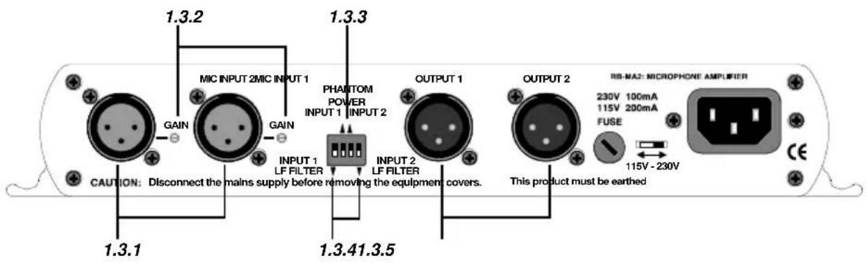
Fig 1-4: RB-MA2 Rear Panel
1-2 Redbox User Handbook
1.3.1. Mic Inputs
The XLR 3 pin sockets used for the microphone are electronically balanced. They have the following connections:
Pin 1: Screen
Pin 2: Phase
Pin 3: Non-phase
1.3.2. Input Gain
Recessed pre-set potentiometers allow for adjustment of the gain of the microphone inputs. This provides a gain range of 36dB to 75dB which enables the use of dynamic and powered microphones. Connect the mic input and adjust the gain until the line output is at the level that you need.

flowchart
graph TD
    A["1"] --> B["2"]
    B --> C["3"]
    C --> D["4"]
    style A fill:#fff,stroke:#000
    style B fill:#fff,stroke:#000
    style C fill:#fff,stroke:#000
    style D fill:#fff,stroke:#000
- Channel 1 Low Frequency (L.F.) Filter
- Channel 1 Phantom Power
- Channel 2 Phantom Power (only applies to MA2)
- Channel 2 Low Frequency (L.F.) Filter (only applies to MA2)
Fig 1-4: Switch to Control LF Filter and Phantom Power
1.3.3. Using Phantom Powered Microphones
For the input channel there are independent switches to provide phantom power at +48V to the connected microphones. With phantom power selected, a voltage of +48V is applied to pins 2 and 3 of the XLR connector to power the microphone, supplied through 6k8 resistors giving a current of 14mA. Phantom power is used when the switch is pointing towards the arrow.
1.3.4. Using the LF Filter
A switch also provides control for a high pass filter with low frequency roll off at 125Hz. The roll-off filter is in when the switch is in the down position (towards the arrow).
1.3.5. Output
The XLR 3 pin plug output connector is electronically balanced and can be wired unbalanced by grounding the non-phase signal, allowing you to feed balanced and unbalanced equipment. It has the following connections:
Pin 1: Screen
Pin 2: Phase
Pin 3: Non-phase
The connector provides a line level output with an impedance of <50Ω and a maximum output level of +28dBu.
1.4. Technical Specifications
1.4.1. Audio Specifications
Maximum Input Level: -10dBu
Maximum Output Level: +28dBu
Input Impedance: 20kΩ nominal balanced
Output Impedance: <50Ω
Low Frequency Roll-Off: 125Hz @ 6dB/octave
Gain Range: Adjustable 36dB to 75dB gain
E.I.N: 130dB
Distortion: 0.01% THD @ 1kHz, ref +8dBu output
Common Mode Rejection: >66dB typically
Phantom Power: 48V
Frequency Response: 20Hz to 20kHz ± 0.1dB (600Ω load, ref 1kHz)
1.4.2. Connections
Input: 1 (2 on RB-MA2) x XLR 3 pin female (Balanced)
Output: 1 (2 on RB-MA2) x XLR 3 pin male (Balanced, can be unbalanced)
Mains Input: Filtered IEC, 110V-120V, or 220-240V switchable, fused, 6W maximum
1.4.3. Equipment Type
RB-MA1:
Single
microphone
amplifier
RB-MA2:
Dual
microphone
amplifier


1.4.4. Physical Specifications
Dimensions (Raw):
28cm (W) × 10.8cm (D) × 4.2cm (H) (1U)
Dimensions (Boxed):
36cm (W) × 20.5cm (D) × 6cm (H)
Weight RB-MA1:
Nett: 0.90kg Gross: 1.35kg
Weight RB-MA2:
Nett: 1.00kg Gross: 1.45kg
2. RB-SM1 Single & RB-SM2 Dual Stereo To Mono Converter
2.1. Introduction

Fig 2-1: RB-SM1 & RB-SM2 Front Panel
The RB-SM1 consists of an independent converter that will produce a fully buffered and balanced mono line output from a stereo input. The RB-SM2 consists of two independent converters and will produce two fully buffered and balanced mono line outputs from two stereo inputs.
All connections are on the rear panel. The XLR-3 inputs are electronically balanced with an impedance of 20kΩ bridging. These can be wired unbalanced to accept an output from domestic equipment.
The XLR-3 line output's are electronically balanced with an output impedance of < 50Ω . The output's can be wired unbalanced by grounding the non-phase signal, allowing you to feed both balanced and unbalanced equipment.
Output gain adjustment using a pre-set potentiometer for both converters allows a normalised mono output from domestic stereo equipment. The potentiometer is accessible through the rear panel. An LED power indicator on the front panel displays the power supply connection.
The rest of this manual will refer to the SM1 unless stated otherwise.
2.2. System Block Diagram

flowchart
graph LR
    A["Left"] --> B["Summing amplifier"]
    C["Right"] --> B
    B --> D["Professional balanced mono output"]
    E["Gain"] --> B
Fig 2-2: RB-SM1 & RB-SM2 Block Diagram Single Channel
2.3. Rear Panel Connections and Operation
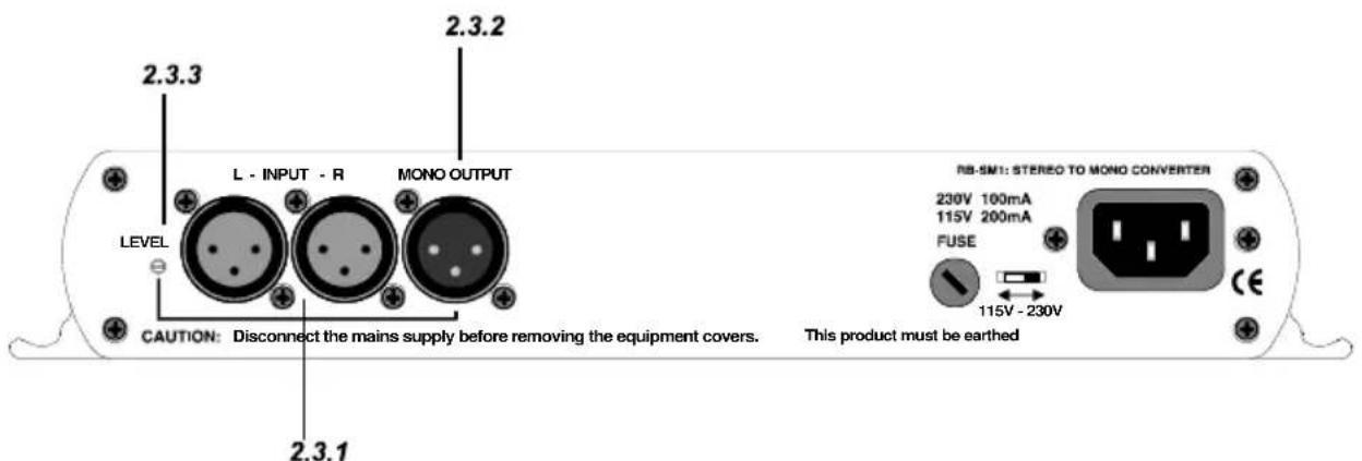
Fig 2-3: RB-SM1 Rear Panel

Fig 2-4: RB-SM2 Rear Panel
2.3.1. Stereo Inputs 1 (& 2)
The input's are a stereo pair consisting of two XLR 3 pin sockets electronically balanced with an impedance of 20kΩ bridging. They can be wired unbalanced to accept an output from domestic equipment. They have the following connections:
Pin 1: Screen
Pin 2: Phase
Pin 3: Non-phase
2.3.2. Mono Output 1 (& 2)
The XLR 3 pin mono output connectors are electronically balanced with an output impedance of <50Ω . They can be wired unbalanced by grounding the non-phase signal, enabling you to feed both balanced and unbalanced equipment. The output has the following connections:
Pin 1: Screen
Pin 2: Phase
Pin 3: Non-phase
2.3.3. Output Gain
Output gain adjustment using a pre-set potentiometer for the converters allows a normalised mono output from domestic stereo equipment. The potentiometers are accessible through the rear panel and provide a gain range of 8dB loss to 18dB gain.
2.4. Technical Specifications
2.4.1. Audio Specifications
Maximum Input Level: +28dBu
Maximum Output Level: +28dBu
Input Impedance: >20kΩ balanced bridging
Output Impedance: <50Ω balanced
Frequency Response: 20Hz to 20kHz ± 0.1dB (600Ω load, ref 1kHz)
Gain Range: Adjust 8dB loss to 18dB gain, ref 0dB input on L and R
Common Mode Rejection: >66dB typically
Distortion: 0.01% THD @ 1kHz, ref +8dBu output
Noise: -100dB unity gain, ref +8dBu output
2.4.2. Connections
Inputs: 2 (4 on RB-SM2) x XLR 3 pin female (Balanced, can be unbalanced)
Output: 1 (2 on RB-SM2) x XLR 3 pin male (Balanced, can be unbalanced)
Mains Input: Filtered IEC, 110V-120V, or 220-240V switchable, fused, 6W maximum
2.4.3. Equipment Type
RB-SM1: Dual stereo to mono converter
RB-SM2: Single stereo to mono converter


2.4.4. Physical Specifications
Dimensions (Raw): 28cm (W) x 10.8cm (D) x 4.2cm (H) (1U)
Dimensions (Boxed): 36cm (W) x 20.5cm (D) x 6cm (H)
Weight RB-SM1: Nett: 1.00kg Gross: 1.45kg
Weight RB-SM2: Nett: 1.05kg Gross: 1.50kg
3. RB-UL1 Single, RB-UL2 Dual & RB-UL4 Quad Stereo Unbalanced To Balanced Converters
3.1 Introduction

Fig 3-1: RB-UL1 & RB-UL2 Front Panel

Fig 3-2: RB-UL4 Front Panel
The RB-UL1 single, RB-UL2 dual & RB-UL4 quad stereo units are used for interfacing domestic, or semi-pro unbalanced equipment to professional balanced line levels.
All connections are on the rear panel. The RCA unbalanced inputs have an impedance of 10kΩ bridging and are routed to the balanced XLR-3 outputs with an output impedance of <50Ω.
The RB-UL1 has two inputs & outputs, the RB-UL2 has four inputs & outputs and the RB-UL4 has eight inputs & outputs.
The output gain can be individually adjusted for left and right channels by using pre-set potentiometers accessible through the rear panel. A LED power indicator on the front panel displays the power supply connection.
3.2 System Block Diagram

flowchart
graph LR
    A["Input -L consumer unbalanced"] --> B["Phono"]
    B --> C["Gain"]
    C --> D["Professional balanced output -L"]
    E["Input -R consumer unbalanced"] --> F["Phono"]
    F --> G["Gain"]
    G --> H["Professional balanced output -R"]
Fig 3-3: RB-UL1 Block Diagram For a Single Channel
3.3 Rear Panel Connections and Operation

Fig 3-4: RB-UL1 Rear Panel

Fig 3-5: RB-UL2 Rear Panel

Fig 3-6: RB-UL4 Rear Panel
3.3.1. RCA Phono Inputs (Left and Right)
The stereo left and right RCA inputs are unbalanced and have an impedance of 10kΩ . They are routed to the stereo balanced XLR 3 pin output connectors.
3.3.2. Outputs (Left and Right)
The XLR 3 pin output plug connectors are electronically balanced with an output impedance of <50Ω. They have the following connections:
Pin 1: Screen
Pin 2: Phase
Pin 3: Non-phase
3.3.3. Output Level Adjustment
The output gain can be individually adjusted for left and right channels through pre-set potentiometers which are accessible through the rear panel. The gain range of the unbalanced to balanced converter is -15dBu to +15dBu ref -15dBu into the unbalanced input.
3.4 Technical Specifications
3.4.1. Audio Specifications
Maximum Input Level: +28dBu
Input Impedance: >10kΩ
Output Impedance: <50Ω
Maximum Output Level: +28dBu
Distortion: 0.01% THD @ 1kHz ref +8dB output
Noise: -100dB unity gain, ref +8dB output
Common Mode Rejection: >66dB typically
Frequency Response: 20Hz to 20kHz ± 0.1dB (600Ω load, ref 1kHz)
Gain Range: Balanced output: -15dBu to 15dBu, ref -15dBu into unbalanced RCA input
3.4.2. Connections
Inputs: 2, 4 (RB-UL2) or 8 (RB-UL4) x RCA phono (unbalanced)
Outputs: 2, 4 (RB-UL2) or 8 (RB-UL4) x XLR 3 pin male (balanced)
Mains Input: Filtered IEC, 110V-120V, or 220-240V switchable, fused, 6W maximum
3.4.3. Equipment Type
RB-UL1: Single stereo unbalanced to balanced converter
RB-UL2: Dual stereo unbalanced to balanced converter


RB-UL4: Quad stereo unbalanced to balanced converter

3.4.4. Physical Specifications
RB-UL1 & RB-UL2:
Dimensions (Raw): 28cm (W) x 10.8cm (D) x 4.2cm (H) (1U)
Dimensions (Boxed): 36cm (W) x 20.5cm (D) x 6cm (H)
Weight RB-UL1: Nett: 1.00kg Gross: 1.45kg
Weight RB-UL2: Nett: 1.05kg Gross: 1.5kg
RB-UL4:
Dimensions (Raw): 48cm (W) x 10.8cm (D) x 4.2cm (H) (1U)
Dimensions (Boxed): 53cm (W) x 20.5cm (D) x 6cm
Weight: Nett: 1.3kg Gross: 1.9kg
4. RB-LU4 Quad Stereo Balanced To Unbalanced Converter
4.1. Introduction

Fig 4-1: RB-LU4 Front Panel
The RB-LU4 is a quad stereo unit for interfacing professional balanced equipment to domestic, or semi-pro unbalanced line levels.
All connections are on the rear panel. The eight XLR-3 electronically balanced inputs have an impedance of 20kΩ bridging and are routed to eight unbalanced RCA phono outputs with an output impedance of <50Ω.
The output gain can be individually adjusted for left and right channels by using pre-set potentiometers accessible through the rear panel. An LED power indicator is situated on the front panel, which displays the power supply connection.
4.2. System Block Diagram

flowchart
graph TD
    A["Input 1 -L professional balanced"] --> B["Phono"]
    C["Input 1 -R professional balanced"] --> D["Phono"]
    E["Input 2 -L professional balanced"] --> F["Phono"]
    G["Input 2 -R professional balanced"] --> H["Phono"]
    I["Input 3 -L professional balanced"] --> J["Phono"]
    K["Input 3 -R professional balanced"] --> L["Phono"]
    M["Input 4 -L professional balanced"] --> N["Phono"]
    O["Input 4 -R professional balanced"] --> P["Phono"]
    B --> Q["Gain"]
    D --> R["Gain"]
    F --> S["Gain"]
    H --> T["Gain"]
    J --> U["Gain"]
    L --> V["Gain"]
    N --> W["Gain"]
    P --> X["Gain"]
    Q --> Y["Consumer unbalanced output 1 -L"]
    R --> Z["Consumer unbalanced output 1 -R"]
    S --> AA["Consumer unbalanced output 2 -L"]
    T --> AB["Consumer unbalanced output 2 -R"]
    U --> AC["Consumer unbalanced output 3 -L"]
    V --> AD["Consumer unbalanced output 3 -R"]
    W --> AE["Consumer unbalanced output 4 -L"]
    X --> AF["Consumer unbalanced output 4 -R"]
Fig 4-2: RB-LU4 Block Diagram
4.3. Rear Panel Connections and Operation

Fig 4-3: RB-LU4 Rear Panel
4.3.1. Inputs 1-4 (Left and Right)
The XLR 3 pin sockets used for the left and right channel inputs of Input 1 are electronically balanced and have an impedance of 20kΩ bridging. They are routed to an unbalanced RCA (phono) output with an output impedance of <50Ω. Each XLR has the following connections:
Pin 1: Screen
Pin 2: Phase
Pin 3: Non-phase
4.3.2. RCA Phono Outputs 1-4 (Left and Right)
These RCA (phono) outputs are unbalanced and have an output impedance of <50Ω .
4.3.3. Output Level Adjustment
The output gain can be individually adjusted for left and right channels through pre-set potentiometers which are accessible through the rear panel. The gain of the balanced to unbalanced converter is variable within a range of -28dBu to +15dBu ref. -15dBu into the balanced input.
4.4. Technical Specifications
4.4.1. Audio Specifications
Maximum Input Level: +28dBu
Input Impedance (XLR): >20kΩ balanced bridging
Output Impedance (RCA): <50Ω
Maximum Output Level: +22dBu
Distortion: 0.01% THD @ 1kHz, ref +8dBu output
Noise: -100dB, unity gain, ref +8dBu output
Common Mode Rejection: >66dB typically
Frequency Response: 20Hz to 20kHz ± 0.1dB (600Ω load, ref 1kHz)
Gain Range: Unbalanced Output : -28dBu to +15dBu, ref -15dBu into balanced XLR input
4.4.2. Connections
Inputs: 8 x XLR 3 pin female (Balanced)
Outputs: 8 x RCA phono (Unbalanced)
Mains Input: Filtered IEC, 110V-120V, or 220-240V switchable, fused, 6W maximum
4.4.3. Equipment Type
RB-LU4: Quad stereo balanced to unbalanced converter

4.4.4. Physical Specifications
Dimensions (Raw): 48cm (W) x 10.8cm (D) x 4.2cm (H) (1U)
Dimensions (Boxed): 53cm (W) x 20.5cm (D) x 6cm (H)
Weight: Nett: 1.3kg Gross: 1.9kg
5. RB-BL2 Single & RB-BL4 Dual Bi-Directional Matching Converter
5.1. Introduction

Fig 5-1: RB-BL2 Front Panel

Fig 5-2: RB-BL4 Front Panel
The RB-BL2 is a bi-directional stereo unit for interfacing domestic, or semi-pro unbalanced equipment to professional balanced line levels, and vice-versa. The RB-BL4 has dual bi-directional stereo capability.
All connections are on the rear panel. The XLR-3 electronically balanced inputs have an impedance of 20kΩ bridging and are routed to unbalanced RCA (phono) outputs with an output impedance of <50Ω.
The RCA unbalanced inputs have an impedance of 10kΩ bridging and are routed to balanced XLR-3 outputs with an output impedance of <50Ω.
The output gain can be individually adjusted for left and right channels by using pre-set potentiometers accessible through the rear panel. An LED power indicator on the front panel displays the power supply connection.
5.2. System Block Diagram

flowchart
graph LR
    subgraph_Input_1_L["Input 1 -L professional balanced"]
        A1["●"] --> B1["△"] --> C1["△"] --> D1["●"] --> E1["○"] --> F1["○"]
        G1["●"] --> H1["△"] --> I1["△"] --> J1["●"] --> K1["○"]
        L1["●"] --> M1["△"] --> N1["△"] --> O1["●"] --> P1["○"]
        Q1["●"] --> R1["△"] --> S1["△"] --> T1["●"] --> U1["○"]
        V1["●"] --> W1["△"] --> X1["△"] --> Y1["●"] --> Z1["○"]
        AA1["●"] --> AB1["△"] --> AC1["△"] --> AD1["●"] --> AE1["○"]
        AF1["●"] --> AG1["△"] --> AH1["△"] --> AI1["●"] --> AJ1["○"]
        AK1["●"] --> AL1["△"] --> AM1["△"] --> AN1["●"] --> AO1["○"]
        AP1["●"] --> AQ1["△"] --> AR1["△"] --> AS1["●"] --> AT1["○"]
        AU1["●"] --> AV1["△"] --> AW1["△"] --> AX1["●"] --> AY1["○"]
        AZ1["●"] --> BA1["△"] --> BB1["△"] --> BC1["●"] --> BD1["○"]
        BE1["●"] --> BF1["△"] --> BG1["△"] --> BH1["●"] --> BI1["○"]
        BJ1["●"] --> BK1["△"] --> BL1["△"] --> BM1["●"] --> BN1["○"]
        BO1["●"] --> BP1["△"] --> BQ1["△"] --> BR1["●"] --> BS1["○"]
        BT1["●"] --> BU1["△"] --> BV1["△"] --> BW1["●"] --> BX1["○"]
        BY1["●"] --> BZ1["△"] --> CA1["△"] --> CB1["●"] --> CC1["○"]
        CY1["●"] --> CZ1["△"] --> DA1["△"] --> DB1["●"] --> DC1["○"]
        DY1["●"] --> DY2["△"] --> DY3["△"] --> DY4["●"] --> DY5["○"]
        DY6["●"] --> DY7["△"] --> DY8["△"] --> DY9["●"] --> DY0["○"]
        DY0 --> DY0A["Gain"]
        DY0B["Gain"] --> DY0C["Gain"]
    end
    subgraph_Input_1_R["Input 1 -R professional balanced"]
        A2["●"] --> B2["△"] --> C2["△"] --> D2["●"] --> E2["○"] --> F2["○"]
        G2["●"] --> H2["△"] --> I2["△"] --> J2["●"] --> K2["○"]
        L2["●"] --> M2["△"] --> N2["△"] --> O2["●"] --> P2["○"]
        Y2["Gain"] --> Y3["Gain"]
    end
    subgraph_Input_2_L["Input 2 -L consumer unbalanced"]
        A3["Phono"]
        B3["Gain"]
        Z3["Gain"]
    end
    subgraph_Input_2_R["Input 2 -R consumer unbalanced"]
        A4["Gain"]
        B4["Gain"]
    end
    subgraph Input 2_L_R-professional balance
        A5["Gain"]
        B5["Gain"]
    end
    subgraph Input 2_RProfessional balance
        A6["Gain"]
        B7["Gain"]
    end
Fig 5-3: RB-BL2 Block Diagram Single Stereo Channel
5.3. Rear Panel Connections and Operation

Fig 5-4: RB-BL2 Rear Panel

Fig 5-5: RB-BL4 Rear Panel
5.3.1. Balanced to Unbalanced Connections
5.3.1.1. Inputs 1 (& 3) (Left & Right)
The XLR 3 pin sockets used for the left and right channel signals of Input 1 / 1 & 3 are electronically balanced and have an impedance of 20kΩ bridging. They are routed to an unbalanced RCA (phono) outputs with an output impedance of <50Ω. Each XLR has the following connections:
Pin 1: Screen.
Pin 2: Phase.
Pin 3: Non-phase.
5.3.1.2. RCA Phono Outputs 1 (& 3) (Left & Right)
These RCA (phono) outputs are unbalanced and have an output impedance of <50Ω .
5.3.1.3. Output Level Adjustment
The output gain can be individually adjusted for left and right channels through preset potentiometers which are accessible through the rear panel. The gain of the balanced to unbalanced converter is variable within a range of 0dBu to -28dBu ref -0dBu into the balanced input.
5.3.2. Unbalanced to Balanced Connections
5.3.2.1. RCA Phono Inputs 2 (& 4) (Left & Right)
The two / four left and right RCA inputs are unbalanced and have an impedance of 10kΩ. They are routed to the two / four balanced XLR 3 pin output connectors.
5.3.2.2. Outputs 2 (& 4) (Left & Right)
The XLR 3 pin output plug connectors are electronically balanced with an output impedance of <50Ω . They have the following connections:
Pin 1: Screen.
Pin 2: Phase.
Pin 3: Non-phase.
5.4. Technical Specifications
5.4.1. Audio Specifications
Maximum Input Level: +28dBu
Maximum Output Level: +28dBu
Input Impedance (RCA): >10kΩ unbalanced
Input Impedance (XLR): >20kΩ balanced bridging
Output Impedance (RCA): <50Ω
Output Impedance (XLR): <50Ω
Distortion: 0.01% THD @ 1kHz, ref +8dBu output
Noise: -100dB, unity gain, ref +8dBu output
Common Mode Rejection: >66dB typically
Frequency Response: 20Hz to 20kHz ± 0.1dB (600Ω load, ref 1kHz)
Gain Range: Unbalanced Output : -28dBu to +15dBu, ref -15dBu into balanced XLR input
Gain Range: Balanced Output : -15dBu to +15dBu, ref -15dBu into unbalanced RCA input
5.4.2. Connections
Inputs: 2 (4 on RB-BL4) x XLR 3 pin female (balanced),
2 (4 on RB-BL4) x RCA phono (unbalanced)
Outputs: 2 (4 on RB-BL4) x XLR 3 pin male (balanced),
2 (4 on RB-BL4) x RCA phono (unbalanced)
Mains Input: Filtered IEC, 110V-120V, or 220-240V switchable, fused, 6W maximum
5.4.3. Equipment Type
RB-BL2: Single Stereo Bi-Directional Matching Converter
RB-BL4: Dual Stereo Bi-Directional Matching Converter
5.4.4. Physical Specification
RB-BL2:
Dimensions (Raw): 28cm (W) x 10.8cm (D) x 4.2cm (H) (1U)
Dimensions (Boxed): 36cm (W) x 20.5cm (D) x 6cm (H)
Weight: Nett: 1.0kg Gross: 1.4kg
RB-BL4:
Dimensions (Raw) 48cm (W) x 10.8cm (D) x 4.2cm (H) (1U)
Dimensions (Boxed) 53cm (W) x 20.5cm (D) x 6cm (H)
Weight Nett: 1.3kg Gross: 1.9kg
6. RB-SL2 Twin Mono, or Stereo, Limiter 6.1. Introduction

Fig 6-1: RB-SL2 Front Panel
The RB-SL2 is a stereo, or twin independent mono, VCA limiter for use in news-rooms and other locations where the correct level into recording equipment is required, but not necessarily under the control of an engineer, for example, for overload protection. It can also be used as an inexpensive main output limiter for low cost radio installations, RSL's, hospital and student radio.
The XLR-3 electronically balanced inputs and outputs can be wired unbalanced to accept an output from domestic equipment. For each channel there is an input gain and a threshold level control.
A rear panel switch changes the unit from dual mono to stereo, when only the pre-sets for channel 1 (left) are active and apply to both channels. An LED power indicator on the front panel displays the power supply connection.
6.2. System Block Diagram

flowchart
graph TD
    A["Balanced professional input L"] --> B["->"]
    C["Select stereo/mono"] --> D["Gain and limit control"]
    E["Balanced professional input R"] --> F["->"]
    G["Limiter stage"] --> H["->"]
    I["Balanced professional output L"] --> J["->"]
    K["Limiter stage"] --> L["->"]
    M["Balanced professional output R"] --> N["->"]
    O["Gain and limit control"] --> P["->"]
    Q["Limiter stage"] --> R["->"]
    S["Balanced professional output L"] --> T["->"]
    U["Balanced professional input L"] --> V["->"]
Fig 6-2: RB-SL2 Block Diagram
6.3. Rear Panel Connections and Operation

Fig 6-3: RB-SL2 Rear Panel
6.3.1. Outputs
The XLR 3 pin plug connectors are electronically balanced and can be wired unbalanced to accept an output from domestic equipment. They have the following connections:
Pin 1: Screen
Pin 2: Phase
Pin 3: Non-phase
6.3.2. Inputs
The XLR 3 pin sockets are electronically balanced, and can be wired unbalanced to accept an output from domestic equipment. They have the following connections:
Pin 1: Screen
Pin 2: Phase
Pin 3: Non-phase
6.3.3. Gain
Each channel has an input gain (GAIN) and a threshold level control (LIMIT LEVEL).
Setting the limit level to maximum (fully anti-clockwise) enables the input through to output to be normalised using the input gain potentiometers. Once the unit is acting as a buffer with gain/attenuation, the limit level can be set, with the recovery adjusted for the application. Limiting is indicated by the power LED on the front panel flashing.
6.3.4. Mode
This switch changes the unit from dual mono to stereo mode. In stereo mode, only the pre-sets for channel 1 (left) are active and they are applied to both channels. Stereo limiting operates by limiting both left and right outputs if either left or right input needs to be limited. Dual mono limiting operates by limiting left and right signals individually – you can use the RB-SL2 as two separate mono limiters.
6.4. Technical Specifications
6.4.1. Audio Specifications
Maximum Input Level: +28dBu
Maximum Output Level: +28dBu
Input Impedance: >20kΩ bridging
Output Impedance: <50Ω
Input Gain: Adjustable -8dBu to +18dBu gain
Limit Threshold: Adjustable -8dBu to +28dBu
Frequency Response: 20Hz to 20kHz ± 0.1dB (600Ω load, ref 1kHz)
Noise: -100dB unity gain, ref + 8dBu
Distortion: 0.01% THD @ 1kHz ref +8dBu output, threshold set at
+ 10dBu
Common Mode Rejection: >66dB typically
6.4.2. Connections
Inputs: 2 x XLR 3 pin female (Balanced, can be unbalanced)
Outputs: 2 x XLR 3 pin male (Balanced, can be unbalanced)
Mains Input: Filtered IEC, 110V-120V, or 220-240V switchable, fused, 6W maximum
6.4.3. Equipment Type
RB-SL2: Twin mono, or stereo, limiter

6.4.4. Physical Specifications
Dimensions (Raw): 28cm (W) x 10.8cm (D) x 4.2cm (H) (1U)
Dimensions (Boxed): 36cm (W) x 20.5cm (D) x 6cm (H)
Weight: Nett: 1.0kg Gross: 1.45kg
7. RB-DA6 6 Way Stereo Distribution Amplifier
7.1. Introduction

Fig 7-1: RB-DA6 Front Panel
The RB-DA6 is a high performance 6 way stereo analogue audio distribution amplifier for splitting a source to a number of different outputs. The RB-DA6 has 1 stereo input and 6 stereo outputs. It can also be configured so that 1 mono input can be distributed to 12 outputs.
The XLR-3 inputs and outputs are electronically balanced and can be wired unbalanced. Each output is individually buffered so that a short circuit on one won't affect the others. The outputs can be wired unbalanced.
The left and right input gain controls (normalising) are pre-set potentiometers accessible through the front panel. The 1-12 mono, 1-6 stereo switch is recessed on the front panel to prevent accidental knocking. An LED power indicator on the front panel displays the power supply connection.
7.2. System Block Diagram

flowchart
graph TD
    subgraph Left_Channeluted_Layer
        A1["Node 1"] --> B1["△"]
        A2["Node 2"] --> B1
        A3["Node 3"] --> B1
        A4["Node 4"] --> B1
        A5["Node 5"] --> B1
        A6["Node 6"] --> B1
    end

    subgraph Right_Channeluted_Layer
        B1 --> C1["△"]
        B2 --> C1
        B3 --> C2["△"]
        B4 --> C2
        B5 --> C2
        B6 --> C2
    end

    Left_Channeluted_Layer -->|Gain| Left_Channeluted_input["Input"]
    Right_Channeluted_Layer -->|Gain| Right_Channeluted_input["Input"]
    Left_Channeluted_Layer -->|Stereo/mono| Right_Channeluted_input["Output"]
    Right_Channeluted_Layer -->|Stereo/mono| Right_Channeluted_input["Output"]

    style Left_Channeluted_Layer fill:#f9f,stroke:#333
    style Right_Channeluted_Layer fill:#bbf,stroke:#333
Fig 7-2: RB-DA6 Block Diagram
7.3. Rear Panel Connections and Operation

Fig 7-3: RB-DA6 Rear Panel
7.3.1. Inputs (Left and Right)
The XLR-3 input connectors can take balanced professional levels, or unbalanced by using the front panel gain controls, and by connecting the non-phase to the signal ground. The input can be configured as either a stereo input with six stereo outputs or a mono input with twelve outputs. The XLR 3 pin input has the following connections:
Pin 1: Screen
Pin 2: Phase
Pin 3: Non-phase
7.3.2. Stereo Outputs 1-6 (Mono Outputs 1-12)
The XLR 3 pin outputs are electronically balanced, and can be wired unbalanced. Each output is individually buffered so that a short circuit on one output will not affect the others. They have the following connections:
Pin 1: Screen
Pin 2: Phase
Pin 3: Non-phase
7.4. Front Panel Connections and Controls

Fig 7-4: RB-DA6 Front Panel
7.4.1. Input Gain Control
The output gain may be varied from -8dB to 18db by adjusting the pre-set potentiometers, which are accessible through the holes in the front panel. This is useful for normalising consumer and professional signals to give outputs of -15dBu and 0dBu respectively.
7.4.2. Stereo/ Mono Operation
The mode of operation may be switched between a stereo distributed channel to 6 stereo channels, and a mono channel to 12 mono channels, by the push button on the front panel which is recessed to prevent accidental switching.
7.5. Technical Specifications
7.5.1. Audio Specifications
Maximum Input Level: +28dBu
Maximum Output Level: +28dBu
Input Impedance: >20kΩ bridging
Output Impedance: <50Ω
Frequency Response: 20Hz to 20kHz ± 0.1dB (600Ω load, ref 1kHz)
Gain Range: Adjustable 8dB loss to 18dB gain (L & R adjust).
Distortion: 0.01% THD @1kHz, ref +8dBu output
Noise: -100dB unity gain, ref +8dBu output
Common Mode Rejection: >66dB typically
7.5.2. Connections
Inputs: 2 x XLR 3 pin female (Balanced, can be unbalanced)
Outputs: 12 x XLR 3 pin male (Balanced, can be unbalanced)
Mains Input: Filtered IEC, 110V-120V, or 220-240V switchable, fused, 6W maximum
7.5.3. Equipment Type
RB-DA6: 6 way stereo distribution amplifier

7.5.4. Physical Specifications
Dimensions (Raw): 48cm (W) x 10.8cm (D) x 4.2cm (H) (1U)
Dimensions (Boxed): 53cm (W) x 20.5cm (D) x 6cm (H)
Weight: Nett: 1.3kg Gross: 1.9kg
8. RB-HD1 Stereo Headphone Amplifier 8.1. Introduction

Fig 8-1: RB-HD1 Front Panel
The RB-HD1 is a 1U rack-mount stereo headphone amplifier for driving up to two pairs of professional stereo headphones from a single stereo or mono input. One headphone socket is on the front panel with one on the rear.
The main stereo input uses electronically balanced XLR-3 connectors on the rear panel, which can be wired un-balanced. The output volume for the headphones can be controlled either by a pot situated on the front panel or a VCA signal supplied externally via the remote connector.
A mono input can be mixed into the main headphone feed, for example, for mixing in talkback to the headphones. This has an input level control via a recessed adjustable potentiometer. The mono mix input can also be controlled remotely.
A stereo/mono switch is recessed on the rear panel to prevent accidental knocking. With mono selected, audio is sent to both left and right ear pieces. An LED power indicator on the front panel displays the power supply connection.
8.2. System Block Diagram

flowchart
graph TD
    A["XLR"] --> B["Audio Input Amplifier"]
    C["Audio Input"] --> B
    D["R"] --> B
    E["Push Switch"] --> F["Stereo/Mono Control Switch"]
    G["Mono Mix Input"] --> H["Gain"]
    I["Volume"] --> J["Remote Connector"]
    K["VCA"] --> L["Local/Remote Control Switch"]
    M["Audio Output Amp"] --> N["Stereo Jack Output"]
    O["Volume"] --> P["Volume"]
Fig 8-2: RB-HD1 Block Diagram
8.3. Front Panel Connections and Controls

Fig 8-3: RB-HD1 Front Panel
8.3.1. Stereo Outputs 1-2 (Mono Outputs1-2)
The outputs available on the front and rear panel through 14 " stereo jack sockets are push-pull, designed to drive 150 mW into 32Ω to 600Ω professional headphones. Each output is individually buffered.
8.3.2. Volume Level Control
The volume level control sets the output level of the two stereo headphone sockets. The two headphone outputs have a maximum output of +11dBu.
8.4. Rear Panel Connections and Operation
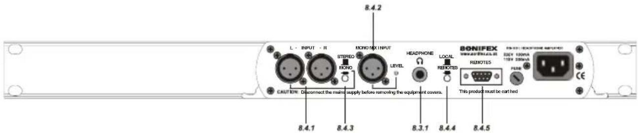
Fig 8-4: RB-HD1 Rear Panel
8.4.1. Stereo Input (Left and Right)
The XLR-3 input connectors can take balanced professional levels, or unbalanced by using the volume control to increase the input level, and by connecting the non-phase to the signal ground. The input can be configured as either a stereo input with two stereo outputs or a mono input with two mono paired outputs. The XLR 3 pin input has the following connections:
Pin 1: Screen
Pin 2: Phase
Pin 3: Non-phase
8.4.2. Mono Mix Input
The XLR-3 input connector can take balanced professional levels, or unbalanced by connecting the non-phase to the signal ground. This input is used for mixing with the main stereo input, which is controlled by the MIX_EN pin (pin 8 on the remote connector) on the remote connector. While this signal is shorted to the ground pin (pin 9 on the remote connector) mixing is enabled and is only disabled once the signal from MIX_EN to pin 9 is open on the remote connector. The XLR 3 pin input has the following connections:
Pin 1: Screen
Pin 2: Phase
Pin 3: Non-phase
A rotary pre-set potentiometer can be used to adjust the gain of the mono mix input by 22dBu.
8.4.3. Stereo/ Mono Operation
The mode of operation may be switched between a stereo channel, or a mono channel to two mono paired outputs (i.e. the same signal to both earpieces), by the push button on the rear panel which is recessed to prevent accidental switching.
8.4.4. Local/ Remote Control Operation
The level to the two outputs can be controlled in one of two ways, either locally, by the pot situated on the front panel or remotely, by a VCA signal supplied externally to the remote connector.
8.4.5. Remote Connector
The remote connector is a 9-pin D-type socket, which is situated on the rear panel. It has connections as shown below.
| Pin No. | Signal I/O Description | ||
| Pin 1 | Pot wiper I Volume control signal | ||
| Pin 2 | Pot top O +5V | ||
| Pin 3 | N/C - No connection | ||
| Pin 4 | N/C - No connection | ||
| Pin 5 | N/C - No connection | ||
| Pin 6 | Pot bottom - Ground | ||
| Pin 7 | N/C - No connection | ||
| Pin 8 | MI X_EN I Make to pin 9 | ||
| Pin 9 | 0V - Ground |
Fig 8-5 RB-HD1 Remote Connector
8.5. Technical Specifications
8.5.1. Audio Specifications
Maximum Input Level: +28dBu
Input Impedance: >20kΩ balanced bridging (main),
10kΩ unbalanced override
Output Level: Drives 150 mW into 32Ω to 600Ω headphones
Volume Control: -80dB to +11dB gain
Mono Mix Input Gain: 22dBu
8.5.2. Connections
Main Stereo Input: 2 x XLR 3 pin female (Balanced, can be wired unbalanced)
Mono Mix Input: 1 x XLR 3 pin female (Balanced, can be wired unbalanced)
Outputs: 2 x 1/4" (6.3mm) A/B gauge 3-pole stereo jack sockets
Remote Control: 9-pin D-type socket
Mains Input: Filtered IEC, 110V-120V, or 220-240V switchable, fused, 9W maximum
8.5.3. Equipment Type
RB-HD1: Stereo headphone amplifier

8.5.4. Physical Specifications
Dimensions (Raw): 48cm (W) x 10.8cm (D) x 4.2cm (H) (1U)
Dimensions (Boxed): 53cm (W) x 20.5cm (D) x 6cm
Weight: Nett: 1.6kg Gross: 2.2kg
9. RB-HD6 6 Way Stereo Headphone Distribution Amplifier
9.1. Introduction

Fig 9-1: RB-HD6 Front Panel
The RB-HD6 is a high performance 6-way stereo headphone distribution amplifier for driving up to 6 pairs of professional stereo headphones from a single stereo or mono input. A switch on the rear panel enables the distribution of a mono signal to all twelve outputs (i.e. both earpieces of a pair of stereo headphones) via the left channel input.
Alternatively, the RB-HD6 can be used as six separate stereo headphone amplifiers by using the override (insert-point, or break-jack) input associated with each outlet. A typical application might be to provide common headphone feeds for guests around a table in a radio studio, with a separately derived feed, perhaps including talkback, for the presenter. The over-ride inputs can also be configured as parallel outputs (to the front outputs) by altering jumper settings inside the unit.
The XLR-3 inputs are electronically balanced and can be wired unbalanced. The input level and output volume controls are all on the front panel. There is a master control that adjusts the level of the master signal to all the outputs, and 6 output level controls. This master control can be disabled by the use of internal jumpers. Each output is designed to drive 150 mW into 32Ω to 600Ω stereo headphones and is individually buffered.
The stereo/mono switch is recessed on the rear panel to prevent accidental knocking. A LED power indicator on the front panel displays the power supply connection.
9.2. System Block Diagram

flowchart
graph TD
    A["XLR"] --> B["Master Input"]
    C["Stereo"] --> D["Adder"]
    E["Push Switch"] --> F["Adder"]
    G["Stereo/Mono Control Switch"] --> H["Adder"]
    I["Master Volume"] --> J["Adder"]
    K["Volume Disable Jumper"] --> L["Adder"]
    M["Adder"] --> N["Audio Output Amp"]
    O["Adder"] --> P["Audio Output Amp"]
    Q["Adder"] --> R["Audio Output Amp"]
    S["Adder"] --> T["Audio Output Amp"]
    U["Adder"] --> V["Audio Output Amp"]
    W["Adder"] --> X["Audio Output Amp"]
    Y["Adder"] --> Z["Audio Output Amp"]
    AA["Adder"] --> AB["Audio Output Amp"]
    AC["Adder"] --> AD["Audio Output Amp"]
    AE["Adder"] --> AF["Audio Output Amp"]
    AG["Adder"] --> AH["Audio Output Amp"]
    AI["Adder"] --> AJ["Audio Output Amp"]
    AK["Adder"] --> AL["Audio Output Amp"]
    AM["Adder"] --> AN["Audio Output Amp"]
    AO["Adder"] --> AP["Audio Output Amp"]
    AQ["Adder"] --> AR["Audio Output Amp"]
    AS["Adder"] --> AT["Audio Output Amp"]
    AU["Adder"] --> AV["Audio Output Amp"]
    AW["Adder"] --> AX["Audio Output Amp"]
    AY["Jumpers"] --> Z
    AZ["Jumpers"] --> AA
    BA["Jumpers"] --> AB
    BB["Jumpers"] --> AC
    BC["Jumpers"] --> AD
    BD["Jumpers"] --> AE
    BEJ["Volume"] --> Z
    BK["Volume"] --> AA
    BL["Volume"] --> AB
    BM["Volume"] --> AC
    BN["Volume"] --> AD
    BO["Volume"] --> AE
    BP["Volume"] --> AF
Fig 9-2: RB-HD6 Block Diagram
9.3. Rear Panel Connections and Operation

Fig 9-3: RB-HD6 Rear Panel
9.3.1. Stereo Input (Left and Right)
The XLR-3 input connectors can take balanced professional levels, or unbalanced by using the front panel master control to increase the input level, and by connecting the non-phase to the signal ground. The input can be configured as either a stereo input with six stereo outputs or a mono input with six mono paired outputs. The XLR 3 pin input has the following connections:
Pin 1: Screen
Pin 2: Phase
Pin 3: Non-phase
9.3.2. Stereo/ Mono Operation
The mode of operation may be switched between a stereo distributed channel to 6 stereo channels, or a mono channel to six mono paired outputs (i.e. the same signal to both ear pieces), by the push button on the rear panel which is recessed to prevent accidental switching.
9.3.3. Channel Insertion Inputs or Parallel Outputs
Each channel has an unbalanced override/insertion input via a 14 " stereo audio jack socket on the rear panel, which overrides the master input.
Each connector can also be individually configured as a parallel output providing the same signal as the output on the front of the unit. To configure the jack connector as an output, you'll need to alter some jumper settings inside the unit.
9.3.3.1. Removing the Equipment Covers
To get inside the RB-HD6, first ensure that it has been disconnected from the mains power and that the mains IEC lead to the unit has been removed. Observing anti-static precautions, undo the four cross-head screws on the back panel at the far left and far right of the panel (2 at each end). Also undo the small brass screws which hold the top and bottom panels to the rear panel. The rear panel should slide backwards out of the unit together with the main circuit board.
9.3.3.2. Configuring Insert Inputs or Parallel Outputs
On the main circuit board, you'll see some jumpers (small black rectangles), the position of which will define whether a particular jack socket operates as an input or output. The drawings below show the different jumper settings available. Each input/output can be configured individually, so you could have three jacks set as inputs and three as outputs if needed.
| Input/Output | 1 | 2 | 3 | 4 | 5 | 6 | |
| Jumpers to Alter | Left | JP1 & 2 | JP5 & 6 | JP9 & 10 | JP13 & 14 | JP17 & 18 | JP21 & 22 |
| Right | JP3 & 4 | JP7 & 8 | JP11 & 12 | JP15 & 16 | JP19 & 20 | JP23 & 24 | |

Once you've set up the jumpers, slide the circuit board back into the Redbox housing using the slots along the inside edge of the metalwork as a guide. Replace the screws on the top, bottom and rear panels of the RB-HD6.
Important Note : The screws provide earthing protection to the chassis and grounding protection for CE approval – it is important that you reinsert all the screws provided.
9.4. Front Panel Connections and Controls

Fig 9-4: RB-HD6 Front Panel
9.4.1. Stereo Outputs 1-6 (Mono Outputs 1-6)
The outputs available on the front panel through 14 " stereo jack sockets are push-pull, designed to drive 150 mW into 32Ω to 600Ω professional headphones. Each output is individually buffered.
9.4.2. Master Level Control
The master level control will set the maximum level of all channels and will need to be set high if an unbalanced consumer input level (-10dbu) is used. This level control can be disabled by setting jumpers within the unit. See Section 11.4.3.1 for details on removing the equipment covers. The two jumpers JP25 and JP26 can be found near the volume potentiometer VR1 :
| Jumper | JP25 | |
| Enable Master Level Control On | On | |
| Disable Master Level Control Off | Off |
JP26
9.4.3. Channel Volume Controls
Each channel has its own volume control so that you have control of the signal volume to an individual output whether it is from the master input or the override input.
9.5. Technical Specifications
9.5.1. Audio Specifications
Input Impedance: >20kΩ balanced bridging (main), >10kΩ unbalanced override
Maximum Input Level: +28dBu
Output Level: Drives 150 mW into 32Ω to 600Ω headphones
Override Inputs: +3dBu for full volume at +18dB gain
Individual Volume Control: -60dB to +18dB gain
Master Volume Control: ±10dB gain
9.5.2. Connections
Main Stereo Inputs: 2 x XLR 3 pin female (Balanced, can be wired unbalanced)
Insert Inputs & 6 x 1/4" (6.3mm) A-gauge 3-pole stereo jack sockets
Parallel Outputs: (unbalanced, jumper configured)
Outputs: 6 x 1/4" (6.3mm) A-gauge 3-pole stereo jack sockets
Mains Input: Filtered IEC, 110V-120V, or 220-240V switchable, fused, 9W maximum
9.5.3. Equipment Type
RB-HD6: 6 way stereo headphone distribution amplifier

9.5.4. Physical Specifications
Dimensions (Raw): 48cm (W) x 10.8cm (D) x 4.2cm (H) (1U)
Dimensions (Boxed): 53cm (W) x 20.5cm (D) x 6cm (H)
Weight: Nett: 1.35kg Gross: 2.0kg
10. RB-SD1 Silence Detection Unit
10.1. Introduction

Fig 10-1: RB-SD1 Front Panel
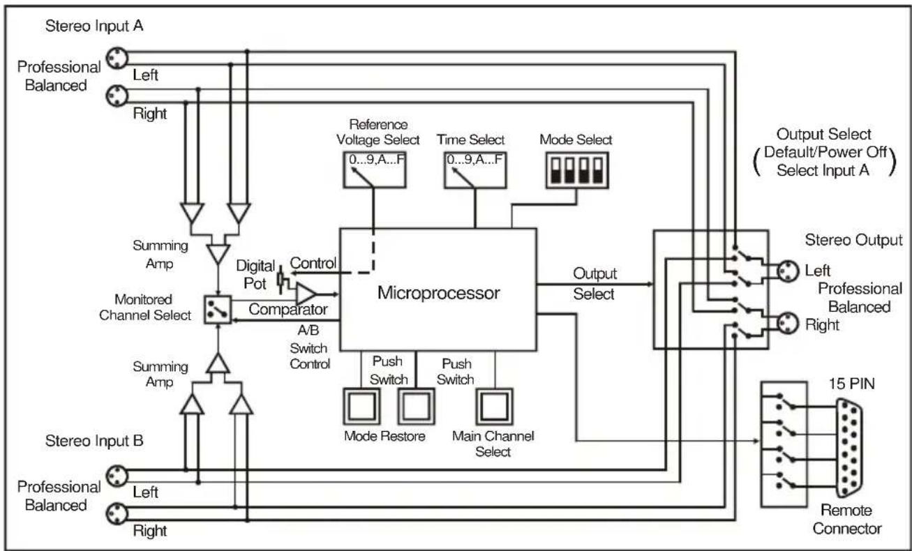
The RB-SD1 Silence Detect Unit is a 1U rack mount device used to monitor an unattended stereo studio feed and in the event of the signal going “quiet” after a given period the unit will switch through an alternative stereo audio signal. This signal could be a recorded message (e.g. “normal service will be resumed”, etc), a feed from a CD player or minidisk machine, or an alternative recorded program. Controls are provided to start external equipment and to provide remote status indication.
It has 2 balanced stereo audio inputs with the maximum input level being +28dBu. Each input is user-defined as either the main source or auxiliary source and both sources are monitored for failure, each having a remote failure alarm. In the event of the main source dropping below a pre-set level for a pre-determined amount of time, the unit will automatically switch through to the auxiliary signal. The silence detect level is adjustable between -60dBu and -15dBu in 3dB steps via a 16 position rotary switch on the rear panel. The silence interval can be adjusted between 2 seconds to 30 seconds in 2 second steps, or, alternatively, set to 2 minutes 5 seconds also via a 16 position rotary switch on the rear panel. The audio outputs use stereo professional balanced XLR-3 male connectors.
The unit can operate in 2 modes - automatic or manual. In both modes it will automatically switch over to the auxiliary source on detecting silence. When the main signal is again detected it will either return to the main signal automatically or manually depending on the mode chosen.
The RB-SD1 has a number of remote operational features. Remote outputs provide separate relay contact closures for failure of the main and auxiliary inputs. You can also control remotely all of the front panel switches for source selection, mode selection and signal Restore. You can remotely start and stop another piece of equipment on alarm failure and main signal return respectively. Also, the longest silence time (2min 5sec) can be set remotely, which is useful if you are expecting to broadcast a long silence.
The unit can be configured to alarm when either the left or right channel of the main input source fails, or if the whole stereo signal fails. There are also options to set the remote start output as momentary or latched, to disable switching to the auxiliary input on alarming and to increase the gain on the auxiliary input so that an unbalanced input can be used, for example, from a domestic minidisc player.
Front panel LED indicators show individually left and right programme and alarm conditions for both the main and auxiliary inputs. The status of the source, mode and alarm state are also shown on the front panel with LED indicators.
Additionally, the RB-SD1 can be programmed for specific applications, which can be defined on power-up of the unit. Contact Sonifex for further information if you have a particular requirement.
The RB-SD1 has been designed to have a passive signal path through the main input, so if power to the unit fails, the signal input will still be routed through to the output. This is essential for applications such as installation at transmitter sites, where a power failure to the unit should not prevent the audio input signal from being output to the transmitter.
10.2. System Block Diagram
flowchart
graph TD
    A["Stereo Input A"] --> B["Professional Balanced"]
    B --> C["Left"]
    B --> D["Right"]
    C --> E["Summing Amp"]
    D --> F["Summing Amp"]
    E --> G["Monitored Channel Select"]
    F --> H["Monitored Channel Select"]
    G --> I["Comparator"]
    H --> I
    I --> J["Microprocessor"]
    J --> K["Output Select"]
    K --> L["15 PIN Remote Connector"]
    L --> M["Remote Connector"]
    M --> N["Main Channel Select"]
    N --> O["Push Switch"]
    O --> P["Mode Restore"]
    O --> Q["Push Switch"]
    P --> R["Microprocessor"]
    Q --> R
    R --> S["Output Select (Default/Power Off) Select Input A"]
    S --> T["Reference Voltage Select 0...9,A...F"]
    S --> U["Time Select 0...9,A...F"]
    S --> V["Mode Select"]
    T --> W["Output Select"]
    U --> W
    V --> W
    W --> X["Stereo Output Left Professional Balanced Right"]
    X --> Y["Output Select"]
Fig 10-2: RB-SD1 Block Diagram
10.3. Rear Panel Connections and Operation

Fig 10-3: RB-SD1 Rear Panel
10.3.1. A/ B Inputs (Left and Right)
There are four XLR-3 inputs, two for channel A (Left & Right) and another two for channel B (Left & Right). The XLR 3 pin sockets are used for the input channels and are electronically balanced. They have the following connections: -
Pin 1: Screen.
Pin 2: Phase.
Pin 3: Non-phase.
10.3.2. Outputs
The stereo input consists of two XLR male connectors professionally balanced with following connections: -
Pin 1: Screen.
Pin 2: Phase.
Pin 3: Non-phase.
10.3.3. Level Control
The level rotary switch (Level) adjusts the input sensitivity gain. The gain may be varied from -15dB to -60db in 3db steps by adjusting the switch, which is accessible on the rear panel.
| Switch | 0 | 1 | 2 | 3 | 4 | 5 | 6 | 7 | 8 | 9 | A | B | C | D | E | F |
| Level dBu | -60 | -57 | -54 | -51 | -48 | -45 | -42 | -39 | -36 | -33 | -30 | -27 | -24 | -21 | -18 | -15 |
10.3.4. Time Control
The time rotary switch (Time) adjusts the duration over which a silence is detected before alarming and ranges from 2-30 seconds (0 - E in 2 second intervals) with F on the switch being a 2 min 5 second silence. This maximum time can also be activated or de-activated remotely via the remote connector.
| Switch | 0 | 1 | 2 | 3 | 4 | 5 | 6 | 7 | 8 | 9 | A | B | C | D | E | F |
| Seconds | 2 | 4 | 6 | 8 | 10 | 12 | 14 | 16 | 18 | 20 | 22 | 24 | 26 | 28 | 30 | 125 |
10.3.5. Mode Dip Switch Settings

- Stereo/Mono.
- Remote Start Mode Switch.
- Professional levels/Consumer levels (Input B).
-
Switch/No switching when alarmed.
-
Stereo/ Mono Switch – The configuration of this defines whether you want to switch sources when left and/or right channel of the incoming source go silent.
| Switch | Description |
| On When | on, the unit operates in stereo mode, whereby if one channel goes quiet the unit will switch, and requires both channels to be present before it switches back. |
| Off When | off, the unit operates in mono mode. In this mode the unit will only switch when both channels go quiet, and requires only one channel to be present before the unit switches back. |
- Remote Start Mode Switch – This defines whether the remote start switch is momentary or latched. Used for starting external equipment when silence is detected.
| Switch | Description |
| On When | on, the remote start pin (pin 15) on the remote connector is pulled low for half a second when the unit switches to the auxiliary input. (Momentary contact). |
| Off | When off, the remote start pin on the remote connector is pulled low when the unit switches over to the auxiliary input and remains low until the unit switches back to the main source or, if in manual mode, is restored by the user locally or remotely. (Latched contact). |
- Professional/ Consumer Switch – This allows you to use an unbalanced piece of equipment as the auxiliary input, by raising the input gain.
| Switch | Description |
| On When | on, Input B accepts professional balanced signal level. |
| Off When | off, Input B accepts consumer unbalanced signal level and raises the input gain received by 12dB. |
- Switch/ No Switching in alarm state – This defines whether the unit switches to the auxiliary input on silence detection.
| Switch | Description |
| On When | on, if the unit goes into the alarm state the unit switches to the auxiliary input. |
| Off When | off, if the unit goes into the alarm state the unit does not switch to the auxiliary input. |
10.3.6. Remotes Connector
Displayed below are the pin connections and descriptions for the remote connector:
| Pin No. | Signal I/O Description | ||
| Pin 1 | Master Alarm Normally Open O Relay 1 N/O to Pin 9 | ||
| Pin 2 | Master Alarm Normally Closed | O Relay 1 N/C to Pin 9 | |
| Pin 3 | Aux. Alarm Normally Open O Relay 2 N/O to Pin 11 | ||
| Pin 4 | Aux. Alarm Normally Closed O Relay 2 N/C to Pin 11 | ||
| Pin 5 | Mode Switch I Momentary make to Pin 8 | ||
| Pin 6 | Mode Indicator O Internal Open Collector to Digital Ground | ||
| Pin 7 | Restore Switch I Momentary make to Pin 8 | ||
| Pin 8 | Digital Ground - - | ||
| Pin 9 | Master Alarm Common O N/O to Pin 1, N/C to Pin 2 | ||
| Pin 10 | Max Time Whilst Latched I Latched make to Pin 8 | ||
| Pin 11 | Aux. Alarm Common O N/O to Pin 3, N/C to Pin 4 | ||
| Pin 12 | +5V O To power up to a maximum 100mA | ||
| Pin 13 | Source Select Indicator O Internal Open Collector to Digital Ground | ||
| Pin 14 | Source Select Switch I Momentary make to Pin 8 | ||
| Pin 15 | Remote Start O Internal Open Collector to Digital Ground | ||
Pins 1 – 4 are for external use to replicate the alarm conditions for the Main and Auxiliary inputs. The Aux alarm output can also be used as Remote Stop pin (See section 12.5.6).
Pins 5 – 7, 13 and 14 are to replicate the switches and indicators for the source select, mode and restore functions.
Pins 8, 9, 11 and 12 are common or voltage pins.
Pin 10 is to select remotely the maximum silence time (2min 5sec). This may be useful for the broadcast of Remembrance Day services, or where you expect a silence of up to 2 minutes to be broadcast. The maximum silence time is set whilst the contact is latched.
Pin 15 is used to remotely start an external piece of equipment and operates on audio fail.
10.4. Front Panel Selectors and Indicators

Fig 10-4: RB-SD1 Front Panel
10.4.1. Source Select and Indicator
The normal Main input source is selectable via a push switch accessed via a hole located on the front panel, or it can be controlled remotely (pins 13 and 14). This allows you to define whether input A, or input B is going to be your Main audio input. There is an LED to indicate which state the source select is set:
| LED | Description |
| LED On Main source is input A, Aux source is input B | |
| LED Off Main source is input B, Aux source is input A | |
Note : If the unit is powered off, for example during a black-out, input A routes through to the output. Therefore if the unit is subject to a power fail while the main source is set to input B, the unit will output source A.
10.4.2. Mode Selector and Indicator
The Mode Switch defines how the unit should operate during an alarm condition, when the main audio source returns. There is an option to allow the device to switch back Automatically or Manually. The mode is selected by a push switch accessed through a hole on the front panel with a corresponding LED to represent its state, or it can be controlled remotely (pins 5 and 6).
| LED | Description |
| LED On Automatic Mode – During an alarm condition when the main source returns, it is switched back automatically, although there must be a continuous signal present for two seconds before it switches. | |
| LED Off Manual Mode – When the alarm condition is reached, the LED begins to flash. | |
| LED Flashing | Manual Mode – The main audio has returned after an alarm condition. To switch to the main source, push the Restore button (or control it remotely). |
10.4.3. Main and Aux indicators
On the front panel there are four Main indicators and four Aux indicators. Each left/right channel has a Program Content and Alarm Status indicator. The Program Content Indicator represents the input signal level for that channel and the Alarm Status LED indicates when the channel has dropped below the threshold for longer than the time selected.
Both the Main and Aux inputs are continuously monitored so that you can check that your backup signal is operating correctly, as well as your main input source.
Note: Although one channel of the stereo input may have alarmed, the main alarm may not be set, due to the setting of the Stereo/Mono Dipswitch.
10.4.4. Alarm Indicator
The Alarm indicator situated on the front panel is used to display the alarm status of the Main input. Its operation is dependant on the selected mode. When in stereo mode the unit alarms on a single main channel timeout, and in mono, alarms on both main channels timing out. The unit exits the alarm state on the return of the main source signal, depending on the setting of the Stereo/Mono Dipswitch. The alarm indicator is remotely indicated on pins 1 and 2 of the remotes connector.
The restore button is used for restoring the main source signal when the unit is operating in Manual Mode. When the main source signal returns after it has timed out, the Mode LED flashes, indicating that the source signal can be restored. When the Restore button is pressed the main source returns. This can be remotely controlled using pin 7 of the remotes connector.
10.4.6. Additional Modes
An option to set the unit in different modes of operation is available and is selectable when the unit is powered on. There are currently four modes of operation, and are as follows: Normal Mode, Remote Stop Mode, Remote Alarm Set Mode and Signal Detection Mode: -
Normal Mode is as described previously for normal machine power-up.
Remote Stop Mode operates as follows. When the main source returns from an alarmed state, pin 4 on the remote connector (Aux Alarm NC) closes to Pin 11 (Aux Alarm Common) for half a second. (Note: this will only occur when the Remote Start Mode Switch is set on (page 10-4) and whilst in Remote Stop Mode, the Aux alarm is not available to indicate the presence of audio on the auxiliary input).
Remote Alarm Set Mode operates as follows. When the RESTORE pin on the remote connector (pin 7) closes to the DIGITAL GROUND pin on the remote connector (pin 8) the unit will immediately enter an alarmed state and switch to the auxiliary input.
This alarm state is continued until the RESTORE pin opens to the DIGITAL GROUND pin. After this the unit will switch back to the main input when audio is present.
NOTE: When operating in manual mode, restoration of output from the main input is only available via the front panel restore switch. All other functions operate as normal.
Signal Detection Mode In this mode the three controls, source, remote source, mode, remote mode, restore and remote restore have no effect.
The count in time for the signal detection is zero, i.e. as soon as signal is detected on an input the relevant relay will switch. The relays operate the same as in normal mode, i.e. when audio is detected on the main input, pin 1 on the remote connector closes to pin 9. When audio is lost on the main input, pin 2 on the remote connector closes to pin 9. All other functions operate as with normal mode.
To set the different modes
Apply power to the unit, and while the front panel ALARM LED is flashing, press and hold the RESTORE button. The MAIN LEFT PROG, MAIN LEFT ALARM, MAIN RIGHT PROG and MAIN RIGHT ALARM LED's should now be flashing alternately. To select Normal Mode release the RESTORE button while the MAIN LEFT PROG LED is on. To select the Remote Stop Mode release the button while the MAIN LEFT ALARM LED is on. To select Remote Alarm Set Mode release the button while the MAIN RIGHT PROG LED is on. To select Signal Detection Mode release the button while the MAIN RIGHT ALARM LED is on.
After the button is released the unit will start working after five seconds. You only have to do this once as the mode is stored in non-volatile memory and you will only need to repeat this procedure if you wish to select a different mode. Each time the unit is powered on; the selected mode is visible by checking which LED is:
MAIN LEFT PROG LED on = Normal Mode
MAIN LEFT ALARM LED on = Remote Stop Mode
MAIN RIGHT PROG LED on = Remote Alarm Set Mode
MAIN RIGHT ALARM LED on = Signal Detection Mode
10.5. Technical Specifications
10.5.1. Audio Specifications
Maximum Input Level: +28dBu
Input Impedance: > 100kΩ balanced
Maximum Output Level: +28dBu
Output Impedance: As input, except when using unbalanced auxiliary input where output impedance < 50Ω
Frequency Response: 20Hz to 20kHz ± 0.1dB
Gain: +12dB (for unbalanced input B - optional)
Noise: < -87dB, input. unity gain, ref + 8c
Distortion: As input for balanced input, <0.05% ref + 8dBu output for unbalanced input.
10.5.2. Connections and Rear Panel Controls
Inputs (Main & Auxiliary): 4 x XLR 3 pin female (balanced, auxiliary can be unbalanced)
Output: 2 x XLR 3 pin male (balanced)
Remotes: 15 way D-type plug
Power: Filtered IEC, 110-120V, or 220-240V switchable, fused, 6W maximum
Alarm Threshold: -15dBu to -60dBu in 3dB steps via rotary switch
Silence Detect Duration: 2 sec to 30 sec in 2 second intervals and 125 second option via rotary switch
Detection Type: Mono or stereo, via dipswitch
Silence Switch Defeat: Disable/enable silence switching, via dipswitch
Remote Start Mode: Latched or momentary, via dipswitch
10.5.3. Front Panel Controls and Indicators
Controls: Source select, mode select and restore
Indicators: Program and alarm indicators for left and right source for both main and auxiliary channels Source, mode and restore LEDs
10.5.4. Equipment Type
RB-SD1: Silence detection unit

10.5.5. Physical Specifications
Dimensions (Raw): 48cm (W) x 10.8cm (D) x 4.2cm (H) (1U)
Dimensions (Boxed): 53cm (W) x 20.5cm (D) x 6cm (H)
Weight: Nett: 1.4kg Gross: 2.0kg
11. RB-PMX4 10 Input, 4 Output Analogue Preset Mixer

Fig 11-1: RB-PMX4 Front Panel
11.1. Introduction
The RB-PMX4 is a high performance 10 mono input to 4 mono output preset mixer. Each of the four outputs has a 10 way DIP switch associated with it to select which of the 10 inputs are routed to it. So, by altering the DIP switches, any of the input sources can be mixed to any of the outputs. The DIP switches are enclosed by a screw-on cover on the front panel so that the settings can not be accidentally changed for secure applications.
The RB-PMX4 has been designed for situations where a small mixer is needed for installations where it will be configured and then only altered occasionally, or never altered. Uses for this product are numerous including a four bus mini-mixer, a 4 zone mixer for pubs and clubs, a multiple clean-feed generator and a quad stereo to mono converter to name a few.
The XLR-3 inputs and outputs are electronically balanced and can be wired unbalanced. Each output is individually buffered so that a short circuit on one won't affect the others. Each input has its own gain control which is a pre-set potentiometer accessible through the front panel. This provides gain adjustment of -8dB to 18db. This is useful for normalizing consumer and professional signals to give outputs of -15dBu and 0dBu respectively.
The front panel is held on by 2 off M3 x 6 stainless steel dome-head screws and can be removed using a 2mm AF hex key (allen key). Each 10-way switch represents an output and the individual switches represent the inputs that will be mixed to that output. Switches are in the ON (down) position to be mixed and the OFF (up) position for off.
The XLR-3 outputs are electronically balanced and can be wired unbalanced. Each output is individually buffered so that a short circuit on one won't affect the others.
An LED power indicator on the front panel displays the power supply connection.
11.2. System Block Diagram
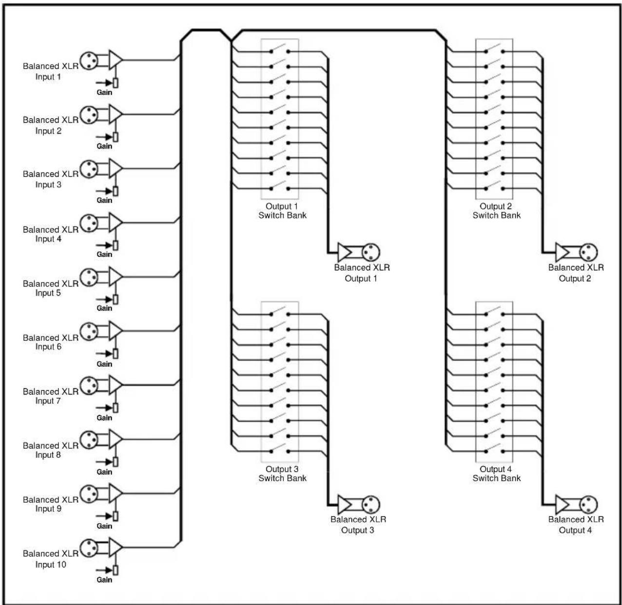
flowchart
graph TD
    A["Balanced XLR Input 1"] -->|Gain| B["Output 1 Switch Bank"]
    C["Balanced XLR Input 2"] -->|Gain| D["Output 1 Switch Bank"]
    E["Balanced XLR Input 3"] -->|Gain| F["Output 1 Switch Bank"]
    G["Balanced XLR Input 4"] -->|Gain| H["Output 1 Switch Bank"]
    I["Balanced XLR Input 5"] -->|Gain| J["Output 1 Switch Bank"]
    K["Balanced XLR Input 6"] -->|Gain| L["Output 1 Switch Bank"]
    M["Balanced XLR Input 7"] -->|Gain| N["Output 1 Switch Bank"]
    O["Balanced XLR Input 8"] -->|Gain| P["Output 1 Switch Bank"]
    Q["Balanced XLR Input 9"] -->|Gain| R["Output 1 Switch Bank"]
    S["Balanced XLR Input 10"] -->|Gain| T["Output 1 Switch Bank"]
    B --> U["Balanced XLR Output 1"]
    D --> V["Balanced XLR Output 1"]
    F --> W["Balanced XLR Output 1"]
    H --> X["Balanced XLR Output 1"]
    J --> Y["Balanced XLR Output 1"]
    L --> Z["Balanced XLR Output 1"]
    N --> AA["Balanced XLR Output 1"]
    O --> AB["Balanced XLR Output 1"]
    P --> AC["Balanced XLR Output 1"]
    R --> AD["Balanced XLR Output 1"]
    T --> AE["Balanced XLR Output 1"]
    U --> AF["Output 2 Switch Bank"]
    V --> AG["Output 2 Switch Bank"]
    W --> AH["Output 2 Switch Bank"]
    X --> AI["Output 2 Switch Bank"]
    Y --> AJ["Output 2 Switch Bank"]
    Z --> AK["Output 2 Switch Bank"]
    AA --> AL["Output 2 Switch Bank"]
    AB --> AM["Output 2 Switch Bank"]
    AC --> AN["Output 2 Switch Bank"]
    AD --> AO["Output 2 Switch Bank"]
    AE --> AP["Output 2 Switch Bank"]
    AF --> AQ["Output 2 Switch Bank"]
    AG --> AR["Output 2 Switch Bank"]
    AH --> AS["Output 2 Switch Bank"]
    AI --> AT["Output 2 Switch Bank"]
    AJ --> AU["Output 2 Switch Bank"]
    AK --> AV["Output 2 Switch Bank"]
    AL --> AW["Output 2 Switch Bank"]
    AM --> AX["Output 2 Switch Bank"]
    AN --> AY["Output 2 Switch Bank"]
    AO --> AZ["Output 2 Switch Bank"]
    AP --> BA["Output 2 Switch Bank"]
    AQ --> BB["Output 2 Switch Bank"]
    AR --> BC["Output 2 Switch Bank"]
    AS --> BD["Output 2 Switch Bank"]
    AT --> BE["Output 2 Switch Bank"]
    AU --> BF["Output 2 Switch Bank"]
    AV --> BG["Output 2 Switch Bank"]
    AW --> BH["Output 2 Switch Bank"]
Fig 11-2: RB-PMX4 Block Diagram
11.3. Rear Panel Connections and Operation

Fig 11-3: RB-PMX4 Rear Panel
11.3.1. Inputs 1-10
The XLR-3 input sockets can take balanced professional levels, or unbalanced by using the front panel gain controls, and by connecting the non-phase to the signal ground screen. The XLR 3 pin input has the following connections:
Pin 1: Screen
Pin 2: Phase
Pin 3: Non-phase
11.3.2. Outputs 1-4
The XLR 3 pin output plugs are electronically balanced, and can be wired unbalanced. Each output is individually buffered so that a short circuit on one output will not affect the others. They have the following connections:
Pin 1: Screen
Pin 2: Phase
Pin 3: Non-phase
11.4. Front Panel Controls

Fig 11-4: RB-PMX4 Front Panel Controls
11.4.1. Switch Banks
There are 4 off 10-way switch banks, one for each output. Using these switches, each input channel can be individually selected to each output. When the switches are up (OFF) position, they are off and mixed when in the down (ON) position.
11.4.2. Input Gain Controls
The gain for each input may be individually varied from -8dB to 18dB by adjusting the pre-set potentiometers, which are accessible through the holes in the front panel. This is useful for normalising consumer and professional signals to give outputs of -15dBu and 0dBu respectively.
11.5. Technical Specifications
11.5.1. Audio Specifications
Maximum Input Level: +28dBu
Input Impedance: >20kΩ balanced bridging
Maximum Output Level: +28dBu
Output Impedance: <50Ω
Frequency Response: 20Hz to 20kHz ±0.1dBu (600 Ω load, @ 1kHz)
Input Gain Range: Adjustable 8dBu loss to 18dBu gain.
Common Mode Rejection: >60dBu typically
Off-isolation/Crosstalk: >90dBu @ 1kHz
Noise: -86dBu RMS 22Hz-22kHz, unity gain, ref +8dB
Distortion: <0.01% @ 1kHz, 0dBu to +26dBu
11.5.2. Connections
Inputs: 10 x XLR 3 pin female (Balanced, can be unbalanced)
Outputs: 4 x XLR 3 pin male (Balanced, can be unbalanced)
Mains Input: Filtered IEC, 110V-120V, or 220-240V switchable, fused, 6W maximum
11.5.3. Equipment Type
RB-PMX4: 10 input, 4 output analogue preset mixer

11.5.4. Physical Specifications
Dimensions (Raw): 48cm (W) x 10.8cm (D) x 4.2cm (H) (1U)
Dimensions (Boxed): 53cm (W) x 20.5cm (D) x 6cm
Weight: Nett: 1.5kg Gross: 2.2kg
12. RB-LI2 Stereo Line Isolation Unit
12.1. Introduction

Fig 12-1: RB-LI2 Front Panel
The RB-LI2 stereo line isolation unit is used to isolate audio signals from inter area ground hum loops, which could be caused by equipment being powered by different mains power supplies, or different phases on the same supply. The input and output are connected together through a transformer, which has internal jumpers allowing the outputs to be balanced about ground.
There is also a loop-through output, so that the RB-LI2 can be inserted into a line, forming a transformer balanced distribution point.
This unit is useful where audio is required to be driven over a relatively long length of cable. By isolating the signal using transformers, ground loop currents that can be present in non-isolated signals, are eradicated completely.
12.2. System Block Diagram

flowchart
graph LR
    A["Input"] --> B["Adder"]
    C["Loop Output"] --> B
    B --> D["Gain"]
    D --> E["Jumper"]
    E --> F["Isolated Output"]
    style A fill:#f9f,stroke:#333
    style C fill:#f9f,stroke:#333
    style D fill:#ccf,stroke:#333
    style E fill:#cfc,stroke:#333
    style F fill:#fcc,stroke:#333
    subgraph Transformer Balanced Mode
        B --> C
        D --> E
        E --> F
    end
    subgraph X2
Fig 12-2: RB-LI2 System Block Diagram
12.3. Rear Panel Connections and Operation

Fig 12-3: RB-LI2 Rear Panel
12.3.1. Inputs
There are 2 input XLR 3 pin sockets. They have the following connections:
Pin 1: Screen
Pin 2: Phase
Pin 3: Non-phase
12.3.2. Isolated Outputs
Each of the 2 inputs has a corresponding isolated output, an XLR 3 pin plug with the following connections:
Pin 1: Screen
Pin 2: Phase
Pin 3: Non-phase
12.3.3. Loop Outputs
Each of the 2 inputs has a corresponding loop-through output, an XLR 3 pin plug with the following connections:
Pin 1: Screen
Pin 2: Phase
Pin 3: Non-phase
12.3.4. Output Level Adjustment
The isolated outputs can be individually adjusted using pre-set potentiometers, which are accessible through the rear panel. The gain range of the stereo line isolation unit is -15dB to +13.5dB (28.5dB).
12.3.5. Internal Jumpers
The unit has jumpers that are used to balance the output about ground. By default these are not fitted when the unit leaves the factory.
To get inside the RB-LI2, first ensure that it has been disconnected from the mains power and that the mains IEC lead to the unit has been removed. Observing anti-static precautions, undo the four-crosshead screws on the back panel at the far left and far right of the panel (2 at each end). Also undo the small brass screws, which hold the top and bottom panels to the rear panel. The rear panel should slide backwards out of the unit together with the main circuit board.

Fig 12-4: Jumper Positions on the RB-LI2 PCB
12.4. Technical Specifications
12.4.1. Audio Specification
Output Impedance: <150Ω
Frequency Response: 10Hz to 36kHz ± 0.5dB
Common Mode Rejection: <64dB
Distortion: 0.5% THD @ 40Hz, ref +17dBu output
Noise: -100dB unity gain ref +8dB
Gain Range: -15dB to +13.5dB (28.5dB)
12.4.2. Connections
Inputs: 2 x XLR 3 pin female
Isolated Outputs: 2 x XLR 3 pin male
Loop Outputs: 2 x XLR 3 pin male
12.4.3. Equipment Type
RB-LI2: Stereo Line Isolation Unit

12.4.4. Physical Specifications
Dimensions (Raw): 28cm (W) x 10.8cm (D) x 4.2cm (H) (1U)
Dimensions (Boxed): 36cm (W) x 20.5cm (D) x 6cm (H)
Weight: Nett: 1.10kg Gross: 1.50kg
13. RB-PLI 6 6 Way Mono Passive Line Isolation Unit
13.1. Introduction

Fig 13-1: RB-PLI6 Front Panel
The RB-PLI6 6 way mono passive line isolation unit is used to isolate audio signals from inter area ground hum loops, which could be caused by equipment being powered by different mains power supplies or phases on the same supply.
The input and output are connected together through a transformer and the unit has internal jumpers allowing the inputs and/or outputs to be balanced about ground. The unit requires no mains power for operation.
This unit is useful where audio is required to be driven over a relatively long length of cable. By isolating the signal using transformers, ground loop currents that can be present in non-isolated signals, are eradicated completely.
13.2. System Block Diagram
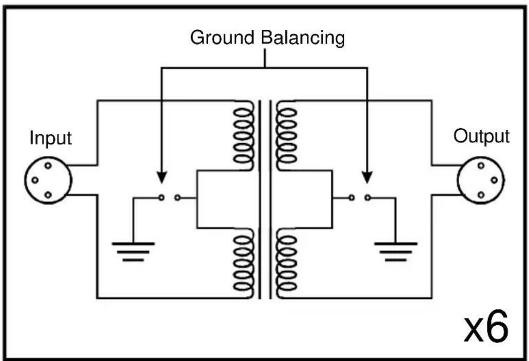
flowchart
graph TD
    A["Input"] --> B["Ground Balancing"]
    B --> C["Output"]
    style A fill:#f9f,stroke:#333
    style B fill:#ccf,stroke:#333
    style C fill:#cfc,stroke:#333
Fig 13-2: RB-PLI6 System Block Diagram
13.3. Rear Panel Connections and Operation

Fig 13-3: RB-PLI6 Rear Panel
13.3.1. Inputs
There are 6 off XLR 3 pin socket inputs. They have the following connections:
Pin 1: Screen
Pin 2: Phase
Pin 3: Non-phase
13.3.2. Outputs
There are 6 off XLR 3 pin plug outputs. They have the following connections:
Pin 1: Screen
Pin 2: Phase
Pin 3: Non-phase
13.3.3. Ground-link Internal Jumpers
The unit has jumpers that are used to balance either the input, or the output, about ground. By default these are not fitted when the unit leaves the factory.
To get inside the RB-PLI6, observing anti-static precautions, undo the four crosshead screws on the back panel at the far left and far right of the panel (2 at each end). Also undo the small brass screws, which hold the top and bottom panels to the rear panel. The rear panel should slide backwards out of the unit together with the main circuit board.

Fig 13-4: RB-PLI6 Ground-link Jumper Settings
13.4. Technical Specifications
13.4.1. Audio Specification
Output Impedance: <150Ω
Distortion: 0.5% THD @ 40Hz, ref +17dBu output
Common Mode Rejection: <64dB typically
Frequency Response: 10Hz to 36kHz ± 0.5dB
13.4.2. Connections
Inputs: 6 x XLR 3 pin female (balanced)
Outputs: 6 x XLR 3 pin male (balanced)
13.4.3. Equipment Type
RB-PLI6: 6 Way Mono Passive Line Isolation Unit

13.4.4. Physical Specifications
Dimensions (Raw): 48cm (W) x 10.8cm (D) x 4.2cm (H - 1U nominally)
Dimensions (Boxed): 53cm (W) x 20.5cm (D) x 6cm
Weight: Nett: 1.5kg Gross: 1.9kg
14. RB-SS10 10 Way Stereo Analogue Source Selector/ Mixer
14.1. Introduction

Fig 14-1: RB-SS10 Front Panel
The RB-SS10 10 Way Stereo Analogue Source Selector/Mixer is a 1U rack-mount unit that produces a stereo analogue audio output from 10 selectable stereo analogue sources. There are 10 illuminated front panel push buttons, which select and indicate the current channel selection. The selection and indication is also available through a remote connector on the rear panel. To stop accidental front panel selection there is a remote input to inhibit the front panel buttons.
As well as being able to act as a source select module, the RB-SS10 can act as a mixer, by enabling the mix mode (using the remote input).
The gain for left and right inputs can be individually adjusted by using the preset potentiometers on the front panel.
As well as routing the selected audio signal, the unit will also route a remote signal input through the remote connector to the selected input source, for starting external audio equipment such as a CD player.
The front panel headphone output has its own volume control, which is independent of the level adjustment for the main outputs, and has a maximum output level of +12dBu. The volume control can be made to also alter the output level of the main XLR outputs by using a switch on the rear panel to enable/disable this feature.
There is a designation strip on the front panel, useful for giving the buttons a meaningful description. The strip covers the input gain controls so that once configured, they can't easily be altered – ideal for installation work.
The LED on the front panel is used to indicate that power is present on the unit.
14.2. System Block Diagram

flowchart
graph TD
    A["Inputs"] --> B["Audio Inputs 1-2"]
    B --> C["Input Gain Stage"]
    C --> D["MCU"]
    D --> E["Status Outputs"]
    C --> F["Analogue Switches"]
    F --> G["Output"]

    subgraph Inputs
        H["L"] --> I["R"]
        J["L"] --> K["R"]
        L["Audio Inputs 3-6"] --> M["Audio Inputs 7-10"]
    end

    subgraph Audio Inputs
        N["L"] --> O["R"]
        P["L"] --> Q["R"]
        R["Audio Inputs 3-6"] --> S["Audio Inputs 7-10"]
    end

    subgraph Outputs
        T["Push Button Switches"] --> U["Switch Inputs"]
        V["Front Panel Inhibit"] --> W["MCU"]
        X["Mix Mode"] --> W
        Y["Remote Start In"] --> W
        Z["Remote Start I/O"] --> W
    end

    style Inputs fill:#f9f,stroke:#333
    style Outputs fill:#ccf,stroke:#333
Fig 14-2: RB-SS10 System Block Diagram
14.3. Front Panel Indicators & Controls

Fig 14-3: RB-SS10 Front Panel
14.3.1. Illuminated Push Buttons
The front panel contains 10 illuminated push buttons, used for selecting an analogue source. The push button illuminates when the input is selected. The status of pin 12 on the remote connector determines whether the unit is in the selector mode, or the mix mode. When pin 12 is connected to 0V, mix mode is enabled.
In selector mode, one push of a button will select the desired analogue stereo source and pushing the button again will turn it off.
In mix mode, each button you press will select that source allowing multiple sources to be mixed to a single output. Pressing the button again will switch off a source.
There is also a remote input to inhibit the front panel switches. When the front panel inhibit is active, pressing the front panel switches has no effect on the current channel selection.
14.3.2. Front Panel Gain Controls
The input gain can be individually adjusted for left and right channels through pre-set potentiometers which are accessible through the rear panel. The gain range of the input is -8dBu to +20dBu.
14.3.3. Headphone Output
The front panel headphone output is a 14 " stereo jack socket and is designed to drive 150mW into 32Ω - 600Ω professional headphones.
14.3.4. Volume Control
The volume control is used to alter the headphone output. It can also be used to alter the main XLR output levels by using a rear panel switch to enable/disable the control.
14.4. Rear Panel Connections and Operation
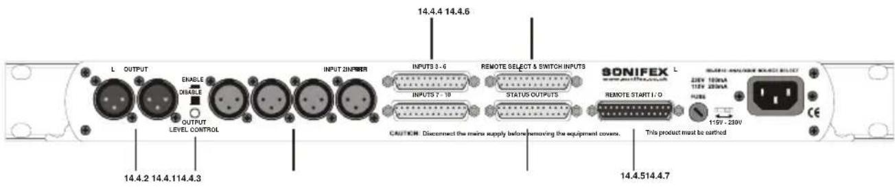
Fig 14-4 : RB-SS10 Rear Panel
14.4.1. Inputs
Four of the analogue audio inputs are on XLR-3 pin sockets (female) so that they can be used for equipment which you may want to plug/unplug on a regular basis and isn't pre-wired, e.g. portable recorders.
The four XLR-3 inputs can take balanced professional levels, or unbalanced by using the front panel gain controls, and by connecting the non-phase to the signal ground. They have the following connections:
Pin 1: Screen
Pin 2: Phase
Pin 3: Non-phase
14.4.2. Outputs
The two XLR 3 pin outputs are electronically balanced, and can be wired unbalanced. Each output is individually buffered so that a short circuit on one output will not affect the others. They have the following connections:
Pin 1: Screen
Pin 2: Phase
Pin 3: Non-phase
14.4.3. Altering the Master Output Level
When the Output Level Control push-switch is Enabled (pushed in) on the rear panel, it changes the functionality of the front panel volume control to also alter the level of the master output, as well as the headphone volume.
14.4.4. RB-SS10 Additional Audio Input Connectors
There are 2 off 25 way D-type sockets (female) used for the remaining audio inputs. The INPUTS 3 - 6 (upper) connector contains analogue inputs 3-6, and the INPUTS 7 - 10 (lower) connector contains analogue inputs 7-10.
| Pin No. | I/O INPUTS 3 - 6 connector INPUTS 7 - | 10 connector | |
| Pin 1 | Audio input 3 left phase Audio input 7 left phase | ||
| Pin 2 | Chassis ground Chassis ground | ||
| Pin 3 | Audio input 3 right non-phase Audio input 7 right non-phase | ||
| Pin 4 | Audio input 4 left phase Audio input 8 left phase | ||
| Pin 5 | Chassis ground Chassis ground | ||
| Pin 6 | Audio input 4 right non-phase Audio input 8 right non-phase | ||
| Pin 7 | Audio input 5 left phase Audio input 9 left phase | ||
| Pin 8 | Chassis ground Chassis ground | ||
| Pin 9 | Audio input 5 right non-phase Audio input 9 right non-phase | ||
| Pin 10 | Audio input 6 left phase Audio input 10 left phase | ||
| Pin 11 | Chassis ground Chassis ground | ||
| Pin 12 | Audio input 6 right non-phase Audio input 10 right non-phase | ||
| Pin 13 | No internal connection No internal connection | ||
| Pin 14 | Audio input 3 left non-phase Audio input 7 left non-phase | ||
| Pin 15 | Audio input 3 right phase Audio input 7 right phase | ||
| Pin 16 | Chassis ground Chassis ground | ||
| Pin 17 | Audio input 4 left non-phase Audio input 8 left non-phase | ||
| Pin 18 | Audio input 4 right phase Audio input 8 right phase | ||
| Pin 19 | Chassis ground Chassis ground | ||
| Pin 20 | Audio input 5 left non-phase Audio input 9 left non-phase | ||
| Pin 21 | Audio input 5 right phase Audio input 9 right phase | ||
| Pin 22 | Chassis ground Chassis ground | ||
| Pin 23 | Audio input 6 left non-phase Audio input 10 left non-phase | ||
| Pin 24 | Audio input 6 right phase Audio input 10 right phase | ||
| Pin 25 | Chassis ground Chassis ground | ||
Fig 14-5: Analogue Audio Inputs Pin Connections
14.4.5. RB-SS10 Remote Start I/O
This 25 way D-type plug (male) connector contains the remote start input connection and the corresponding 10 opto-isolated remote start outputs. This is intended to be used as a method for re-directing a remote start command using a single switch or mixer fader start output, to selected equipment, i.e. CD player, or MD player, etc. This operates in both selector mode and mix mode enabling a single switch to remotely control whichever source is selected or mixed.
| Pin No. I/O Description | |
| Pin 1 O Start output 1 collector | |
| Pin 2 O Start output 2 collector | |
| Pin 3 O Start output 3 collector | |
| Pin 4 O Start output 4 collector | |
| Pin 5 O Start output 5 collector | |
| Pin 6 O Start output 6 collector | |
| Pin 7 O Start output 7 collector | |
| Pin 8 O Start output 8 collector | |
| Pin 9 O Start output 9 collector | |
| Pin 10 O Start output 10 collector | |
| Pin 11 - No internal connection | |
| Pin 12 - No internal connection | |
| Pin 13 I Remote start input signal | |
| Pin 14 O Start output 1 emitter | |
| Pin 15 O Start output 2 emitter | |
| Pin 16 O Start output 3 emitter | |
| Pin 17 O Start output 4 emitter | |
| Pin 18 O Start output 5 emitter | |
| Pin 19 O Start output 6 emitter | |
| Pin 20 O Start output 7 emitter | |
| Pin 21 O Start output 8 emitter | |
| Pin 22 O Start output 9 emitter | |
| Pin 23 O Start output 10 emitter | |
| Pin 24 - No internal connection | |
| Pin 25 - Signal ground | |
Fig 14-6: Remote Start Pin Connections
The collector connects to the start pin of the equipment, and the emitter connects to the common pin of the equipment.

flowchart
graph LR
    A["Start Output Collector 1 to 10 (Pins 1 to 10)"] --> B["Play Command"]
    C["Start Output Emitter 1 to 10 (Pins 14 to 23)"] --> D["Command Common"]
Fig 14-7: Connection Example
14.4.6. Remote Select/ Switch Inputs
This 25 way D-type socket (female) connector contains the front panel inhibit input connection and the remote switch inputs to control the channel selection.
| Pin No. I/O Description | |
| Pin 1 I Remote input 1 – | active low to ground |
| Pin 2 I Remote input 2 – | active low to ground |
| Pin 3 I Remote input 3 – | active low to ground |
| Pin 4 I Remote input 4 – | active low to ground |
| Pin 5 I Remote input 5 – | active low to ground |
| Pin 6 I Remote input 6 – | active low to ground |
| Pin 7 I Remote input 7 – | active low to ground |
| Pin 8 I Remote input 8 – | active low to ground |
| Pin 9 I Remote input 9 – | active low to ground |
| Pin 10 I Remote input 10 – | active low to ground |
| Pin 11 I Front panel inhibit signal – | active low to ground |
| Pin 12 I Mix Mode – | active low to ground |
| Pin 13 - No internal connection | |
| Pins 14 to 24 - Signal ground | |
| Pin 25 - No internal connection | |
Fig 14-8: Remote Select/ Switch Input Connections
All of the active low signals have internal pull-ups.

Fig 14-9: Connection Example
14.4.7. Status Outputs
This 25 way D-type socket (female) connector contains the remote status tallies.
| Pin No. | Signal Name | I/O | Description |
| Pin 1 | REMT | ALLY1 | O Internal open collector to ground for output 1 |
| Pin 2 | REMT | ALLY2 | O Internal open collector to ground for output 2 |
| Pin 3 | REMT | ALLY3 | O Internal open collector to ground for output 3 |
| Pin 4 | REMT | ALLY4 | O Internal open collector to ground for output 4 |
| Pin 5 | REMT | ALLY5 | O Internal open collector to ground for output 5 |
| Pin 6 | REMT | ALLY6 | O Internal open collector to ground for output 6 |
| Pin 7 | REMT | ALLY7 | O Internal open collector to ground for output 7 |
| Pin 8 | REMT | ALLY8 | O Internal open collector to ground for output 8 |
| Pin 9 | REMT | ALLY9 | O Internal open collector to ground for output 9 |
| Pin 10 | REMT | TALLY10 | O Internal open collector to ground for output 10 |
| Pin 11 | N/C | - | No internal connection |
| Pin 12 | N/C | - | No internal connection |
| Pin 13 | GND | - | Signal ground |
| Pins 14 to 23 | +5V | O To supply up to a maximum of 100mA | |
| Pin 24 | N/C | - | No internal connection |
| Pin 25 | N/C | - | No internal connection |
Fig 14-10: Status Output Pin Connections
Pins 1 to 10 are to replicate the front panel push button indicators. An example of how to connect the signals is shown below.
Pins 11, 12, 24 and 25 have no connection inside the unit.

Fig 14-11: Connection Example
14.5. Technical Specifications
14.5.1. Audio Specifications
Input Impedance: 20kΩ bridging
Output Impedance: <50Ω
Maximum Input Level: +28dBu
Maximum Output Level: +28dBu
Frequency Response: 20Hz to 20kHz ± 0.1dB (600Ω load, ref 1kHz)
Input Gain Range: Adjustable 8dB loss to 20dB gain (L & R adjust).
Common Mode Rejection: >66dB typically
Noise: -96dB unity gain ref + 8dBu
Max Headphone
Output Level: +12dBu
14.5.2. Connections
Inputs: 4 x XLR 3 pin female (balanced, can be unbalanced)
2 x 25 way D-type socket (female) (3 stereo balanced channels on each)
Outputs: 2 x XLR 3 pin male (stereo balanced, can be unbalanced)
Remote Start I/O: 25 way D-type plug (male)
Remote Select/
Switch Inputs: 25 way D-type socket (female)
Status Outputs: 25 way D-type socket (female)
Mains Input: Filtered IEC, 110V-120V, or 220-240V switchable, fused, 6W maximum.
14.5.3. Equipment Type
RB-SS10: 10 way stereo analogue source selector/mixer

14.5.4. Physical Specifications
Dimensions (Raw): 48cm (W) x 10.8cm (D) x 4.2cm (H) (1U)
Dimensions (Boxed): 53cm (W) x 20.5cm (D) x 6cm (H)
Weight: Nett: 1.5kg Gross: 2.0kg
15. RB-LC3 3 Way Light/ Power Controller 15.1. Introduction

Fig 15-1: RB-LC3 Front Panel
The RB-LC3 is a triple output switching unit for controlling external mains indicators, primarily studio status lights for broadcasting applications, such as On-Air, Mic-Live and Rehearsal/Live lights. Each output can be individually controlled by one of three remote inputs (pulled high, or low), by a telephony input (when ringing, or off-hook or both), or a combination of two inputs (to control two outputs, e.g. for Rehearsal/Live situations). The type of control is set using a 12 way DIP switch (4 switches for each output allowing 16 different settings, 14 for control type selection and 2 for operating mode selection).
All connections are on the rear panel. The three IEC outputs are controlled by zero-cross point drivers. When an output is activated, the A.C. voltage level at that output will be equal to the mains input voltage used to power the unit.
External control of the switched mains outputs is via the 15 way D-type plug connector.
The telephone Line input and Handset output are via two RJ11-4 type connectors. The telephone connections are wired pin to pin from Line to Handset except when the remote Ring Mute control input is asserted. In this case the ring signal to the Handset is muted. The status of the telephone Line is continually monitored so that Handset ringing and off-hook conditions can be indicated.
A pre-set potentiometer on the rear panel controls the flash rate of the output when the appropriate mode is selected. Neon indicators on each power socket show the status of the mains output.
An LED power indicator on the front panel displays the incoming power supply connection.
15.2. System Block Diagram
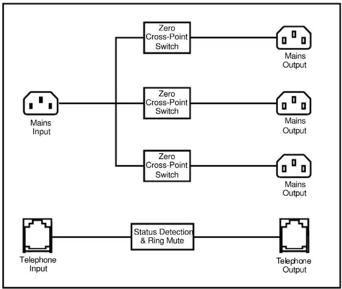
flowchart
graph TD
    A["Mains Input"] --> B["Zero Cross-Point Switch"]
    A --> C["Zero Cross-Point Switch"]
    A --> D["Zero Cross-Point Switch"]
    B --> E["Mains Output"]
    C --> F["Mains Output"]
    D --> G["Mains Output"]
    H["Telephone Input"] --> I["Status Detection & Ring Mute"]
    I --> J["Telephone Output"]
Fig 15-2: RB-LC3 Block Diagram
15.3. Rear Panel Connections and Operation

Fig 15-3: RB-LC3 Rear Panel
15.3.1. Switched Mains Outputs
The 3 off IEC connectors provide the switched mains outputs. Each output is rated at 1A and is individually fused. A neon indicator shows when the output is live. The outputs are driven by zero cross-point drivers. When an output is activated, the A.C. voltage level at that output will be equal to the mains input voltage used to power the unit.
15.3.2. Telephone Connections
The telephone connections are wired pin to pin from Line to Handset except when the Ring Mute control input is asserted. In this case the ring signal to the Handset is muted. The status of the telephone Line is continually monitored so that Handset ringing and off-hook conditions can be indicated.
15.3.3. Remote External Control Inputs
The 15 way D-type connector provides the control inputs that switch the three mains outputs and control the telephone handset ring mute. All inputs have both active high (+5V to +30V) and active low (0V) control. An output-on or “Tally” indication for each output is also provided on this connector in the form of three open-collector driven outputs capable of sinking 20mA each. The connections are as follows:
Pin 1: Remote 1 (Active High)
Pin 2: Remote 1 (Active Low)
Pin 3: Remote 2 (Active High)
Pin 4: Remote 2 (Active Low)
Pin 5: Remote 3 (Active High)
Pin 6: Remote 3 (Active Low)
Pin 7: Ring Mute (Active High)
Pin 8: Ring Mute (Active Low)
Pin 9: Output 1 Tally (Open Collector)
Pin 10: Output 2 Tally (Open Collector)
Pin 11: Output 3 Tally (Open Collector)
Pin 12: No Connection
Pin 13: No Connection
Pin 14: 0V
Pin 15: 0V
15.3.4. Configuration Switches
The configuration switches are used to set the flash mode for each output separately. The selections allow the outputs to be controlled by a remote input, a telephone call, or a combination of remote inputs, say, for example to control 2 lights such as "Rehearsal" and "Live", using Settings 10-13.
The configuration switches are also used to select the operating mode, either latching or momentary, for each output. The operating mode is set when power is applied to the unit and the configuration switches are set to either Setting 15 or 16. The Output will flash once to indicate latching mode has been selected or twice to indicate momentary mode has been selected. The configuration switches can then be returned to the required Setting. In Latching Mode (Setting 15 selected on power up), the Output is On/Flashing only while the selected Remote Inputs remain asserted. In Momentary Mode (Setting 16 selected on power up), each separate assertion of the selected Remote Inputs changes the state of the Output. For example: for setting 4, the first assertion of Remote 1 switches Output 1 on. The second assertion of Remote 1 switches Output 1 off. The operating mode has no effect when using Settings 1-3.
The available settings for output 1, configured using switches Sw1 to Sw4, are detailed below:
| Setting No | Sw 1 | Sw 2 | Sw 3 | Sw 4 | Description |
| 1 Off | Off Off | Off Flash Output | sh Out | put 1 when telephone ringsOutput 1 On when telephone is off-hook | |
| 2 On | Off Off | Off Output 1 | On when telephone is off-hook | ||
| 3 Off | On Off | Off Flash Output | sh Out | put 1 when telephone rings | |
| 4 On | On Off | Off Output 1 | On when Remote 1 asserted | ||
| 5 Off | Off On | Off Output | Output 1 On when Remote 2 asserted | ||
| 6 On | Off On | Off Output | Output 1 On when Remote 3 asserted | ||
| 7 | Off | On | On | Off | Flash Output 1 when Remote 1 asserted |
| 8 On | On | On | Off Flash Output | Output 1 when Remote 2 asserted | |
| 9 | Off | Off | Off | On | Flash Output 1 when Remote 3 asserted |
| 10 | On | Off | Off | On | Output 1 On when Remote 1 or Remote 2 asserted |
| 11 | Off | On | Off | On | Output 1 On when Remote 1 asserted and Remote 2 not asserted |
| 12 | On | On | Off | On | Output 1 On when Remote 1 not asserted and Remote 2 asserted |
| 13 | Off | Off | On | On | Output 1 On when Remote 1 asserted and Remote 2 asserted |
| 14 | On | Off | On | On | Reserved for future assignment |
| 15 | Off | On | On | On | Latching Mode selection for Output 1 |
| 16 | On | On | On | On | Momentary Mode selection for Output 1 |
Fig 15-4: Output 1 Configuration Setting
The available settings for output 2, configured using switches Sw5 to Sw8, are detailed below:
| Setting No | Sw5 | Sw6 | Sw7 | Sw8 | Description |
| 1 Off Off | Off Off | Flash Output 2 | when telephone ringsOutput 2 On when telephone is off-hook | ||
| 2 On Off | Off Off | Output 2 On when telephone is off-hook | |||
| 3 Off On | Off Off | Flash Output 2 when telephone rings | |||
| 4 On On | Off Off | Output 2 On when Remote 1 asserted | |||
| 5 Off Off | On Off | Output 2 On when Remote 2 asserted | |||
| 6 On Off | On Off | Output 2 On when Remote 3 asserted | |||
| 7 | Off | On | On | Off | Flash Output 2 |
| 8 On On | On Off | Flash Output 2 when Remote 2 asserted | |||
| 9 | Off | Off | Off | On | Flash Output 2 when Remote 3 asserted |
| 10 | On Off | Off On | Output 2 On when Remote 1 or Remote 2 asserted | ||
| 11 | Off On | Off On | Output 2 On when Remote 1 asserted and Remote 2 not asserted | ||
| 12 | On On | Off On | Output 2 On when Remote 1 not asserted and Remote 2 asserted | ||
| 13 | Off Off | On On | Output 2 On when Remote 1 asserted and Remote 2 asserted | ||
| 14 | On Off | On On | Reserved for future assignment | ||
| 15 | Off | On | On | On | Latching Mode selection for Output 2 |
| 16 | On On | On On | Momentary Mode selection for Output 2 | ||
when
Fig 15-5: Output 2 Configuration Settings
The available settings for output 3, configured using switches Sw9 to Sw12, are detailed below:
| Setting No | Sw 9 | Sw 10 | Sw 11 | Sw 12 | Description |
| 1 Off Off | Off Off | Flash Output 3 | when telephone ringsOutput 3 On when telephone is off-hook | ||
| 2 On Off | Off Off | Output 3 On when telephone is off-hook | |||
| 3 Off On | Off Off | Flash Output 3 | when telephone rings | ||
| 4 On On | Off Off | Output 3 On when Remote 1 asserted | |||
| 5 | Off | Off | On | Off Output 3 On when Remote 2 asserted | |
| 6 On Off | On | Off Output 3 On when Remote 3 asserted | |||
| 7 | Off | On | On | Off Flash Output 3 when Remote 1 asserted | |
| 8 On On | On | Off Flash Output 3 when Remote 2 asserted | |||
| 9 | Off | Off | Off | On Flash Output 3 when Remote 3 asserted | |
| 10 | On | Off | Off | On Output 3 On when Remote 1 or Remote 2 asserted | |
| 11 | Off On | Off On | Output 3 On when Remote 1 asserted and Remote 2 not asserted | ||
| 12 | On On | Off On | Output 3 On when Remote 1 not asserted and Remote 2 asserted | ||
| 13 | Off | Off | On | On Output 3 On when Remote 1 asserted and Remote 2 asserted | |
| 14 | On Off On | On Reserved for future assignment | |||
| 15 | Off | On | On | On Latching Mode selection for Output 3 | |
| 16 | On On | On | On Momentary Mode selection for Output 3 | ||
Fig 15-6: Output 3 Configuration Settings
15.3.5. Flash Rate Preset Potentiometer
This preset potentiometer sets the rate at which the mains output is switched on/off when one of the Flash Output settings is selected. The range of adjustment is from 0.5 seconds to 2 seconds.
15.4. Technical Specifications
15.4.1. Connections
Mains Input: Non-filtered IEC, 110V-240V auto-adjusting, fused, 6W maximum
Mains Outputs: 3 x Non-filtered IEC plugs, 1A fused
Telephone: 2 x RJ11-4 sockets
Control Inputs & Outputs: 15 way D-type plug
Inputs: 0V-5V DC
Outputs: Open Collector 20mA sink capability
15.4.2. Equipment Type
RB-LC3: 3 way light/power controller

15.4.3. Physical Specifications
Dimensions (Raw): 28cm (W) x 10.8cm (D) x 4.2cm (H) (1U)
Dimensions (Boxed): 36cm (W) x 20.5cm (D) x 6cm (H)
Weight: Nett: 1.00kg Gross: 1.45kg
16. Glossary
1kHz 1000Hz or 1 kilohertz Tone of 1kHz is often used for line-up and testing.
ADSL Asynchronous Digital Subscriber Link - a broadband delivery system over standard telephone lines (between the exchange and the user).
AES Audio Engineering Society.
AES/EBU Professional digital audio standard covering frame format, connections and interfaces. Interface is usually on XLR sockets and plugs.
AM Amplitude Modulation - older analogue modulation standard used on long, medium and short wave.
APT-X Data reduction process for reducing the amount of storage or bit-rate need for audio.
ATRAC Adaptive Transform Acoustic Coding - the data reduction of compression scheme used in Mini-disk machines.
Attenuation The reduction of a signal level. Attenuation is usually measured in dB.
B-Channel Bearer Channel - the main carrier channels used in ISDN.
Balance The relative levels of the left and right channels of a stereo signal.
Balanced Audio A way of sending audio over cable that protects it from induced interference.
CAR See racks room.
CAT 5 Category 5 - type of cabling/connectivity standards used in computer networking.
CD Compact Disc.
Cleanfeed A cleanfeed is a signal produced by a telco module on a mixer which is used as the output to be fed back to a caller on a telephone line. The cleanfeed is a sum of all the other signals which constitute the programme output, except for the caller's audio. A cleanfeed signal will generally be of a better quality than a mix-minus signal.
Clipping The onset of severe distortion in the signal path, usually caused by the peak signal voltage being limited.
CMRR Common Mode Rejection Ratio. This is the ratio of the extent to which a differential amplifier will cancel noise, which is present on both inputs, compared to its ability to amplify the signal.
CODEC COder-DECoder - used to change a signal from one format to anther and back again.
Codecs Using digital circuits being offered by telecom providers, usually ISDN (Integrated Services Data Networks) or other data transfer methods, audio can be transferred with good to excellent quality over what almost amount to dial-up telephone lines. The units operate by Coding the audio into a digital data stream that can be transferred over the digital circuit which is Decoded at the receiving end (Thus CoDec). By using single or multiple circuits, very high quality audio can be transferred from one place to another, even internationally.
Cross-talk This is the amount of a signal from a bus which appears, or is induced, on a different signal. The problem is usually most prevalent with adjacent channels.
DA Distribution Amplifier.
DAB Digital Audio Broadcasting = now called Digital Radio.
DAT Digital Audio Tape.
| dB (decibel) | A ratio of two voltages or signal levels, expressed by the equation dB=20LOG(V1/V2)Adding the suffix "u" denotes that the signal is relative to 0.775V RMS.Adding the suffix "v" denotes that the signal is relative to 1V RMS. |
| DCF This is radio code signal sourced from Mainflingen, near Frankfurt in Germany, which can be used to automatically synchronize the Sentinel+ audio logger and PC time to an accurate atomic clock, European Time. | |
| DDS & DDS-2 DDS and DDS-2 are world-wide standards established by Sony and Hewlett-Packard which introduce many levels of error checking as data is written to a DAT tape. DDS(-2) drives and tapes are used in security products all over the world. 120m DDS-2 DAT tapes are more accurate and reliable than DDS tapes and are able to store twice as much audio data. | |
| DI Direct Inject - a means of driving audio, usually from an instrument such as a guitar, to allow the audio signal to be fed directly into a sound desk input. | |
| DLS Dynamic Label segment - a text message scheme used in digital radio, usually to carry information about the programme. Like the radio-text scheme used in RDS. | |
| DSP Digital Signal Processing. | |
| EBU European Broadcasting Union. | |
| EIN Equivalent input noise. It is the ratio of output noise to the gain. It describes the level of noise which would need to be fed into an ideal amplifier to produce the measured output noise. | |
| ENG (Electronic news gathering). Machines that can record audio and video information digitally. | |
| EON (RDS) Enhance Other Networks - a scheme for switching a listener's radio to another Effective Radiated Power. | |
| EQ (Equalisation). This is a method of cutting or boosting selected bands of frequencies in a signal. | |
| FM Frequency Modulation - a way of sending audio or data over a radio carrier, the 88 - 108 Broadcast Band is often known as the FM Band. | |
| G3 Third generation mobile telephone system that may allow broadband transmission of Global Positioning System. | |
| Gain The degree of amplification, or attenuation, applied to a signal. | |
| GRAM Gramophone Reproducer - a turntable with a 'pick-up' amplifier and remote start interface. | |
| HDLC High Speed Data Link. | |
| Hybrid See T.B.U. | |
| IEC International Elecrotechnical Commission - often used to refer to a mains onnectivity standard, i.e. A type of plug/socket similar to that of a kettle, used on most pro-audio equipment. | |
| ISDN Integrated Services Digital Network - a system for sending high bandwidth material over standard telephone lines. | |
| Kbps Kilo-bits per second - the number os 1s or 0s transmitted or transferred in one second. | |
| kHz Kilo Hertz (samples per second). | |
| LAN Local Area Network - scheme where several computers on the same premises are connected together so that they can exchange data. | |
LCD Liquid Crystal Display (grey displays e.g. on calculators).
LED Light Emitting Diode (small lights e.g. on computers).
LNB Low Noise Block - the RF amplifier attached to a satellite dish.
MCR See racks room.
MDU Mains Distribution Unit - a panel of mains outlets for power distribution.
MF Medium Frequency - another name for Medium Wave - roughly frequencies between 300kHz and 3MHz.
MHz Mega-hertz - One million cycles per second.
Mix-minus A mix-minus is similar to a cleanfeed except that the caller's voice is removed from the signal electronically. Due to phasing problems at the signal band edges, the mix-minus method often produces a lower grade signal.
Mono Monophonic sound (system of broadcasting, recording or reproducing sound) using only one channel between source and loudspeaker.
MP3 MPEG 1 Layer 3 - see MPEG.
MPEG (ISO MPEG) Motion Picture Experts Group. For audio, this is used to refer to a framing format standard. There are several layers and variants. Most common ones are listed below.
MPEG 1 Layer 1 Used for Digital Compact Cassette.
MPEG 1 Layer 2 (Musicam) used in digital radio, digital terrestrial television, ISDN and many hard-disk storage systems.
MPEG 1 Layer 3 Known as MP3. A more elaborate version of MPEG 1 Layer 2 that allows for audio storage using low bit-rates.
MSF This is radio code signal sourced from Rugby in England, which can be used to automatically synchronize the Sentinel+ audio logger and PC time to an accurate atomic clock, UK Time.
Musicam Masking Pattern Universal Sub-Band Encoding.
MUX Short for Multiplex - a 'package' of digital radio services.
Pan This controls the levels sent to the left and right outputs and is an abbreviation of 'panorama'.
PFL (Pre Fade Listen, or Cue). This is a method of auditioning audio material independently of the programme output, without routing the signal to air. The PFL button on each channel routes the signal to the PFL bus, where it can be monitored.
PI Code (RDS) Programme Information Code used to identify an FM RDS station.
PPM Peak Performance Meter (BBC Specification).
Promo Something used to promote a product.
PS Name (RDS) Programme Service Name - 8 characters used for naming an FM RDS station.
PSU Power Supply Unit.
PTY (RDS and DAB) Programme Type. A code transmitted to describe the overall programme content of a radio station (Static PTY) and/or the moment by moment content (Dynamic PTY). RDS has 32 codes although 3 are used in special circumstances only.
Racks Room Often called the Master Control Room (MCR) or Central Apparatus Room (CAR), the racks room is an engineering area containing studio routing to transmitter equipment. Outside sources, phone-in equipment, off-air and transmitter status monitoring and logging equipment (or the transmitter itself!) are stored here with limited access.
RDS Radio Data System.
Reverb An echo (in very basic terms).
RF Radio Frequency.
RJ-45 A connection standard used in computer networking.
S/PDIF Sony/Phillips Digital Interface. Domestic digital audio interface standard using phono connectors or optically using fibre-optic connectors.
SPL Sound Pressure Level.
TA Traffic Announcement (flag) - a means of signalling to a radio with FM RDS indicating that traffic/travel news is being broadcast.
T/B Talk-back (and reverse talk-back). This is the ability for two or more studios to communicate with each other off-air.
TBU See Telephone Balance Unit
TCP/IP Transmission Control Protocol / Internet Protocol. Computer interconnection methodology used on the internet and LANs.
Telephone Balance Unit (TBU) or Hybrid Telephone hybrids provide the interface between professional audio equipment and the public telephone network. They provide protection for your equipment and the public telephone lines, allowing for varying line signals and line conditions. Automatically cancelling out the unwanted signal they also facilitate two-way communication down a single telephone line. In most European countries, including the UK, the TBU must be approved for connection to telephone company lines. Sonifex TBU's carry British Telecom and pan European approval.
THD The Total Harmonic Distortion is the percentage presence of signals outside the measured reference frequency.
TMC (RDS) Traffic Message Channel.
TP Traffic Programme (flag) - a means of indicating to an RDS radio that a station will carry traffic announcements.
U A height measurement for rack-mount equipment:
1U = 1.75 inches
2U = 3.5 inches
3U = 5.25 inches
4U = 7 inches
UPS Uninterruptible Power Supply. A device which maintains power to equipment when the electricity supply fails.
VHF Very High Frequency - frequencies between 30MHz and 300MHz.
VP Vertical Polarisation i.e. of FM radio transmission.
VSWR Voltage Standing Wave Radio
VU Voltage units
WAP Wireless Application Protocol - a system for delivering mini-web pages to mobile phones from the Internet.
X21 A data communications protocol used in synchronous connections.
XLR Professional, robust lockable audio connector - sometimes known as a 'Cannon' after one of the earlier manufacturers.
17. Connectors And Cabling
Many of the problems associated with installing and maintaining studio equipment are due to the use of poor cables or faulty connections. It is recommended that, wherever possible, pre-wired cables are purchased from recommended manufacturers. If you need bespoke cables making, please ensure that a qualified engineer carries out the work.
The main types of connectors used with the Redboxes are the following:
17.1. XLR 3 Pin Connectors
The following diagram shows the pin details for the 3 pin XLR sockets and plugs:
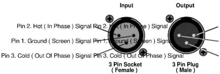
Fig 17-1 : XLR Connectors
17.2. RCA Phono Connectors
The following diagram shows the connection details for the RCA phono connectors:

Fig 17-2 : RCA Phono Connector
17.3. 14 " Jack Connector
The following diagram shows the connection details for the jack connector:
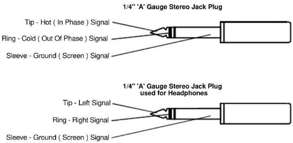
Fig 17-3 : 14 " Jack Connector
17.4. D-Type Connector
The following diagram shows the connection details for the D-type connectors as viewed from the rear of a Redbox :

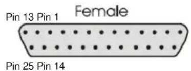
Fig 17-4 : 25 Way D-Type Connectors


Fig 17-5 : 15 Way D-Type Connectors
Index
A
Alarm Indicators
RB-SD1, 10-7
Atmosphere, iv
Automatic Mode
RB-SD1, 10-6
B
Block Diagram
RB-SM1, 2-2
RB-SM2, 2-2
C
Cabling, 17-1
Channel Volume
RB-HD1, 8-2
RB-HD6, 9-5
Common Mode Rejection
RB-BL2, 5-5
RB-DA6, 7-4, 14-9
RB-LU4, 4-4
RB-PMX4, 11-4
RB-SL2, 6-4
RB-SM1, 2-4
RB-UL1, 3-4
Configuration Switches
RB-LC3, 15-4
Connectors, 17-1
D
Dip Switch Settings
RB-SD1, 10-4
E
Earthing, iii
EI N
RB-MA1, 1-4
Electromagnetic Radiation, iv
F
Flash Rate Preset potentiometer
RB-LC3, 15-6
Front Panel Connections and Controls
RB-DA6, 7-3
RB-HD1, 8-2
RB-HD6, 9-5
Front Panel Drawing
RB-BL4, 5-1
RB-DA6, 7-1
RB-HD1, 8-1
RB-HD6, 9-1
RB-LC3, 15-1
RB-LI2, 12-1
RB-LU4, 4-1
RB-PMX4, 11-1
RB-SD1, 10-1
RB-SS10, 14-1
RB-UL1, 3-1
RB-UL2, 3-1
RB-UL4, 3-1
Front Panel Indicators & Controls
RB-SS10, 14-3
Front Panel Selectors and Indicators
RB-SD1, 10-6
G
Gain
RB-BL2, 5-4
RB-DA6, 7-3
RB-HD1, 8-2
RB-HD6, 9-5
RB-LU4, 4-3
RB-MA1, 1-3
RB-MA2, 1-3
RB-PMX4, 11-4
RB-SL2, 6-3
RB-SM1, 2-3
RB-SM2, 2-3
|
Impedances
RB-BL2, 5-5
RB-DA6, 7-4, 14-9
RB-HD1, 8-4
RB-HD6, 9-6
RB-LU4, 4-4
RB-MA1, 1-4
RB-PMX4, 11-4
RB-SL2, 6-4
RB-SM1, 2-4
RB-UL1, 3-4
Input Gain
RB-DA6, 7-3
RB-MA1, 1-3
RB-MA2, 1-3
RB-PMX4, 11-4
RB-SL2, 6-3
Inputs
RB-BL2, 5-4
RB-DA6, 7-3
RB-HD1, 8-3
RB-HD6, 9-3
RB-LI2, 12-2
RB-LU4, 4-3
RB-PLI6, 13-2
RB-PMX4, 11-3
RB-SD1, 10-3
RB-SL2, 6-3
RB-SM1, 2-3
RB-SM2, 2-3
RB-SS10, 14-4
Internal Jumpers
RB-LI2, 12-3
Introduction
RB-DA6, 7-1
RB-HD1, 8-1
RB-HD6, 9-1
RB-LC3, 15-1
RB-LI2, 12-1
RB-LU4, 4-1
RB-MA1, 1-1
RB-MA2, 1-1
RB-PLI6, 13-1
RB-PMX4, 11-1
RB-SD1, 10-1
RB-SL2, 6-1
RB-SM1, 2-1
RB-SM2, 2-1
RB-SS10, 14-1
RB-UL1, 3-1
Isolated Outputs
RB-LI2, 12-2
L
Level Control
RB-SD1, 10-3
Limit Level
RB-SL2, 6-3
Local / Remote Control Switch
RB-HD1, 8-3
Loop Outputs
RB-LI2, 12-2
M
Manual mode
RB-SD1, 10-6
Mic
RB-MA1
Phantom Power, 1-3
Mic Inputs
RB-MA1, 1-3
RB-MA2, 1-3
Mode
RB-SL2
Dual Mono To Stereo, 6-3
Mode Dip Switch Settings
RB-SD1, 10-4
Mono Mix Input
RB-HD1, 8-3
Mono Outputs
RB-SM1, 2-3
RB-SM2, 2-3
N
Noise
RB-BL2, 5-5
RB-DA6, 14-9
RB-LU4, 4-4
RB-SL2, 6-4
RB-SM1, 2-4
0
Output Gain
RB-BL2, 5-4
RB-LU4, 4-3
RB-SM1, 2-3
Output Level Adjustment
RB-BL2, 5-4
RB-LI2, 12-3
Outputs
RB-BL2, 5-4
RB-LU4, 4-3
RB-MA1, 1-3
RB-PMX4, 11-3
RB-SD1, 10-3
RB-SL2, 6-3
RB-SS10, 14-4
RB-UL1, 3-3
RB-UL2, 3-3
RB-UL4, 3-3
P
Phantom Power Mic Operating
RB-MA1, 1-3
RB-MA2, 1-3
Physical Specifications
RB-DA6, 7-4
RB-HD1, 8-4
RB-HD6, 9-6
RB-LC3, 15-7
RB-LI2, 12-4
RB-LU4, 4-4
RB-MA1, 1-4
RB-MA2, 1-4
RB-PLI6, 13-4
RB-PMX4, 11-4
RB-SD1, 10-9
RB-SL2, 6-4
RB-SM1, 2-4
RB-SM2, 2-4
RB-SS10, 14-9
RB-UL1, 3-4
Power Connection, iv
R
RCA Phono Connectors, 17-1, 17-2
RCA Phono Inputs
RB-BL2, 5-4
RB-LU4, 4-3
RB-UL1, 3-3
RB-UL2, 3-3
RB-UL4, 3-3
RCA Phono Output
RB-BL2, 5-4
Rear Panel Connections and
Operations
RB-BL2, 5-3
RB-DA6, 7-3
RB-HD1, 8-3
RB-HD6, 9-3
RB-LC3, 15-3
RB-LI2, 12-2
RB-LU4, 4-3
RB-MA1, 1-2
RB-MA2, 1-2
RB-PLI6, 13-2
RB-PMX4, 11-3
RB-SD1, 10-3
RB-SL2, 6-3
RB-SM1, 2-2
RB-SM2, 2-2
RB-SS10, 14-4
RB-UL1, 3-2
RB-UL2, 3-2
RB-UL4, 3-3
Remote Connector
RB-SD1, 10-5
Restore Button
RB-SD1, 10-7
Roll-Off Filters
RB-MA1, 1-3
s
Source Select
RB-SD1, 10-6
Stereo/ Mono Operation
RB-DA6, 7-4
RB-HD1, 8-3
RB-HD6, 9-3
Stereo/ Mono Outputs
RB-DA6, 7-3
RB-HD1, 8-2
RB-HD6, 9-5
Switch Banks
RB-PMX4, 11-3
System Block Diagram
RB-BL2, 5-2
RB-DA6, 7-2
RB-HD1, 8-2
RB-HD6, 9-2
RB-LC3, 15-2
RB-LI2, 12-1
RB-LU4, 4-2
RB-MA1, 1-2
RB-MA2, 1-2
RB-PLI6, 13-1
RB-PMX4, 11-2
RB-SD1, 10-2
RB-SL2, 6-2
RB-SS10, 14-2
RB-UL1, 3-2
RB-UL2, 3-2
RB-UL4, 3-2
T
Time Control
RB-SD1, 10-3
V
Volume Control
RB-SS10, 14-3


- Analogue Redbox User Handbook
- Contents
- Warranty, Safety & Installation Information...... i
- RB-MA1 Single & RB-MA2 Dual Microphone Amplifiers 1-1
- RB-SM1 Single & RB-SM2 Dual Stereo To Mono Converter 2-1
- RB-UL1 Single, RB-UL2 Dual & RB-UL4 Quad Stereo Unbalanced To Balanced Converters 3-1
- RB-LU4 Quad Stereo Balanced To Unbalanced Converter 4-1
- RB-BL2 Single & RB-BL4 Dual Bi-Directional Matching Converter 5-1
- RB-SL2 Twin Mono, or Stereo, Limiter 6-1
- RB-DA6 6 Way Stereo Distribution Amplifier....7-1
- RB-HD1 Stereo Headphone Amplifier 8-1
- RB-HD6 6 Way Stereo Headphone Distribution Amplifier 9-1
- RB-SD1 Silence Detection Unit 10-1
- Figures
- Warranty, Safety & Installation Information Warranty Information
- Returning the Warranty Card
- Safety of Mains Operated Redbox Equipment
- Preparing the Machine for Use
- Equipment Safety
- Voltage Setting Checks
- Fuse Rating
- Power Cable and Connection
- Ordering the Correct Mains Lead
- Installation Information
- Atmosphere
- Electromagnetic Radiation
- Fitting Redboxes
- RB-MA1 Single & RB-MA2 Dual Microphone Amplifiers
- Introduction
- System Block Diagram
- Rear Panel Connections and Operation
- 1-2 Redbox User Handbook
- Mic Inputs
- Input Gain
- Using Phantom Powered Microphones
- Using the LF Filter
- Output
- Technical Specifications
- Audio Specifications
- Connections
- Equipment Type
- Physical Specifications
- RB-SM1 Single & RB-SM2 Dual Stereo To Mono Converter
- Introduction
- System Block Diagram
- Rear Panel Connections and Operation
- Stereo Inputs 1 (& 2)
- Mono Output 1 (& 2)
- Output Gain
- Technical Specifications
- Audio Specifications
- Connections
- Equipment Type
- Physical Specifications
- RB-UL1 Single, RB-UL2 Dual & RB-UL4 Quad Stereo Unbalanced To Balanced Converters
- Introduction
- System Block Diagram
- Rear Panel Connections and Operation
- RCA Phono Inputs (Left and Right)
- Outputs (Left and Right)
- Output Level Adjustment
- Technical Specifications
- Audio Specifications
- Connections
- Equipment Type
- Physical Specifications
- RB-LU4 Quad Stereo Balanced To Unbalanced Converter
- Introduction
- System Block Diagram
- Rear Panel Connections and Operation
- Inputs 1-4 (Left and Right)
- RCA Phono Outputs 1-4 (Left and Right)
- Output Level Adjustment
- Technical Specifications
- Audio Specifications
- Connections
- Equipment Type
- Physical Specifications
- RB-BL2 Single & RB-BL4 Dual Bi-Directional Matching Converter
- Introduction
- System Block Diagram
- Rear Panel Connections and Operation
- Balanced to Unbalanced Connections
- Inputs 1 (& 3) (Left & Right)
- RCA Phono Outputs 1 (& 3) (Left & Right)
- Output Level Adjustment
- Unbalanced to Balanced Connections
- RCA Phono Inputs 2 (& 4) (Left & Right)
- Outputs 2 (& 4) (Left & Right)
- Technical Specifications
- Audio Specifications
- Connections
- Equipment Type
- Physical Specification
- RB-SL2 Twin Mono, or Stereo, Limiter 6.1. Introduction
- System Block Diagram
- Rear Panel Connections and Operation
- Outputs
- Inputs
- Gain
- Mode
- Technical Specifications
- Audio Specifications
- Connections
- Equipment Type
- Physical Specifications
- RB-DA6 6 Way Stereo Distribution Amplifier
- Introduction
- System Block Diagram
- Rear Panel Connections and Operation
- Inputs (Left and Right)
- Stereo Outputs 1-6 (Mono Outputs 1-12)
- Front Panel Connections and Controls
- Input Gain Control
- Stereo/ Mono Operation
- Technical Specifications
- Audio Specifications
- Connections
- Equipment Type
- Physical Specifications
- RB-HD1 Stereo Headphone Amplifier 8.1. Introduction
- System Block Diagram
- Front Panel Connections and Controls
- Stereo Outputs 1-2 (Mono Outputs1-2)
- Volume Level Control
- Rear Panel Connections and Operation
- Stereo Input (Left and Right)
- Mono Mix Input
- Stereo/ Mono Operation
- Local/ Remote Control Operation
- Remote Connector
- Technical Specifications
- Audio Specifications
- Connections
- Equipment Type
- Physical Specifications
- RB-HD6 6 Way Stereo Headphone Distribution Amplifier
- Introduction
- System Block Diagram
- Rear Panel Connections and Operation
- Stereo Input (Left and Right)
- Stereo/ Mono Operation
- Channel Insertion Inputs or Parallel Outputs
- Removing the Equipment Covers
- Configuring Insert Inputs or Parallel Outputs
- Front Panel Connections and Controls
- Stereo Outputs 1-6 (Mono Outputs 1-6)
- Master Level Control
- Channel Volume Controls
- Technical Specifications
- Audio Specifications
- Connections
- Equipment Type
- Physical Specifications
- RB-SD1 Silence Detection Unit
- Introduction
- System Block Diagram
- Rear Panel Connections and Operation
- A/ B Inputs (Left and Right)
- Outputs
- Level Control
- Time Control
- Mode Dip Switch Settings
- Remotes Connector
- Front Panel Selectors and Indicators
- Source Select and Indicator
- Mode Selector and Indicator
- Main and Aux indicators
- Alarm Indicator
- Additional Modes
- To set the different modes
- Technical Specifications
- Audio Specifications
- Connections and Rear Panel Controls
- Front Panel Controls and Indicators
- Equipment Type
- Physical Specifications
- RB-PMX4 10 Input, 4 Output Analogue Preset Mixer
- Introduction
- Rear Panel Connections and Operation
- Inputs 1-10
- Outputs 1-4
- Front Panel Controls
- Switch Banks
- Input Gain Controls
- Technical Specifications
- Audio Specifications
- Connections
- Equipment Type
- Physical Specifications
- RB-LI2 Stereo Line Isolation Unit
- Introduction
- System Block Diagram
- Inputs
- Isolated Outputs
- Loop Outputs
- Output Level Adjustment
- Internal Jumpers
- Technical Specifications
- Audio Specification
- Connections
- Equipment Type
- Physical Specifications
- RB-PLI 6 6 Way Mono Passive Line Isolation Unit
- Introduction
- System Block Diagram
- Inputs
- Outputs
- Ground-link Internal Jumpers
- Technical Specifications
- Audio Specification
- Connections
- Equipment Type
- Physical Specifications
- RB-SS10 10 Way Stereo Analogue Source Selector/ Mixer
- Introduction
- System Block Diagram
- Front Panel Indicators & Controls
- Illuminated Push Buttons
- Front Panel Gain Controls
- Headphone Output
- Volume Control
- Rear Panel Connections and Operation
- Inputs
- Outputs
- Altering the Master Output Level
- RB-SS10 Additional Audio Input Connectors
- RB-SS10 Remote Start I/O
- Remote Select/ Switch Inputs
- Status Outputs
- Technical Specifications
- Audio Specifications
- Connections
- Equipment Type
- Physical Specifications
- RB-LC3 3 Way Light/ Power Controller 15.1. Introduction
- System Block Diagram
- Switched Mains Outputs
- Telephone Connections
- Remote External Control Inputs
- Configuration Switches
- Flash Rate Preset Potentiometer
- Technical Specifications
- Connections
- Equipment Type
- Physical Specifications
- Glossary
- Connectors And Cabling
- XLR 3 Pin Connectors
- RCA Phono Connectors
- 14 " Jack Connector
- D-Type Connector
- Index
- A
- B
- C
- D
- E
- F
- G
- |
- Impedances
- Input Gain
- Inputs
- Internal Jumpers
- Introduction
- Isolated Outputs
- L
- Level Control
- Limit Level
- Local / Remote Control Switch
- Loop Outputs
- M
- Manual mode
- Mic
- Mic Inputs
- Mode
- Mode Dip Switch Settings
- Mono Mix Input
- Mono Outputs
- N
- Noise
- 0
- Output Gain
- Output Level Adjustment
- Outputs
- P
- Phantom Power Mic Operating
- Physical Specifications
- Power Connection, iv
- R
- RCA Phono Connectors, 17-1, 17-2
- RCA Phono Inputs
- RCA Phono Output
- Rear Panel Connections and
- Operations
- Remote Connector
- Restore Button
- Roll-Off Filters
- s
- Source Select
- Stereo/ Mono Operation
- Stereo/ Mono Outputs
- Switch Banks
- System Block Diagram
- T
- Time Control
- V
- Volume Control
Brand : Sonifex
Model : Redbox RB-UL2
Category : Audio Amplifier