RM-2S10 - Monitor Sonifex - Free user manual and instructions
Find the device manual for free RM-2S10 Sonifex in PDF.


| Product Type | Passive Studio Monitor |
| Brand | Sonifex |
| Model | RM-2S10 |
| Driver Configuration | 2-way: 10" woofer, 1" tweeter |
| Frequency Response | 50 Hz - 20 kHz (±3 dB) |
| Impedance | 8 ohms |
| Sensitivity | 90 dB SPL (1W/1m) |
| Power Handling | 100 W RMS, 200 W peak |
| Dimensions (H x W x D) | 520 mm x 310 mm x 280 mm |
| Weight | 14.5 kg |
| Cabinet Material | MDF with black laminate |
| Mounting | Rack-mountable (optional kit) |
| Input Connectors | Binding posts (banana plugs) |
| Power Supply | Passive (no internal amplifier) |
| Main Functions | Accurate audio monitoring for broadcast and studio |
| Maintenance & Cleaning | Wipe with a soft, dry cloth; avoid solvents |
| Safety | Do not expose to water or extreme humidity |
| Spare Parts & Repairability | Contact Sonifex support for replacement drivers |
| General Information | Professional-grade passive monitor for critical listening |
Frequently Asked Questions - RM-2S10 Sonifex
User questions about RM-2S10 Sonifex
0 question about this device. Answer the ones you know or ask your own.
Ask a new question about this device
Download the instructions for your Monitor in PDF format for free! Find your manual RM-2S10 - Sonifex and take your electronic device back in hand. On this page are published all the documents necessary for the use of your device. RM-2S10 by Sonifex.
USER MANUAL RM-2S10 Sonifex
natural_image
Close-up of blue industrial equipment components including a 4GB RM 4GB controller and control panels (no readable text or symbols)
Reference Monitors User Handbook
RM-2S4 Reference Monitor, 2 LED meters & 4 stereo channel inputs
RM-2S10 Reference Monitor, 2 LED meters & 10 stereo channel inputs
RM-4C8 Reference Monitor, 4 LED meters, 8 channel inputs & dual selectors
RM-HD1 HD-SDI expansion card
RM-HDE1 HD-SDI & Dolby* E Decoder expansion card


natural_image
Abstract graphic of two stylized swords with a circular emblem, set against a blue gradient background (no text or symbols)This handbook is for use with the following product:
RM-2S4 Reference Monitor, 2 LED meters & 4 stereo channel inputs
RM-2S10 Reference Monitor, 2 LED meters & 10 stereo channel inputs
RM-4C8 Reference Monitor, 4 LED meters, 8 channel inputs & dual selectors
RM-HD1 HD-SDI expansion card
RM-HDE1 HD-SDI & Dolby* E Decoder expansion card
©Sonifex Ltd, 2008
All Rights Reserved
Revision 1.04, August 2008
Sonifex Ltd, 61, Station Road, Irthlingborough,
Northants, NN9 5QE, England.
Tel: +44 (0)1933 650 700
Fax: +44 (0)1933 650 726
Email: sales@sonifex.co.uk
Website: http://www.sonifex.co.uk
Information in this document is subject to change without notice and does not represent a commitment on the part of the vendor. Sonifex Ltd shall not be liable for any loss or damage whatsoever arising from the use of information or any error contained in this manual.
No part of this manual may be reproduced or transmitted in any form or by any means, electronic or mechanical, including photocopying, recording, information storage and retrieval systems, for any purpose other than the purchaser's personal use, without the express written permission of Sonifex Ltd. Unless otherwise noted, all names of companies, products and persons contained herein are part of a completely fictitious adaptation and are designed solely to document the use of Sonifex product.
Warranty i
Warranty and Liability i Unpacking the Reference Monitor iii Returning the Warranty Card iii
Safety Information iv
Safety of Mains Operated Equipment iv Voltage Setting Checks iv Fuse Rating iv Power Cable and Connection iv Ordering the Correct Mains Lead v
Installation Information v
Atmosphere v Electromagnetic Radiation v WEEE & RoHS Directives - Sonifex Statement vi
Reference Monitors Introduction 1
RM-2S4 Reference Monitor, 2 LED meters & 4 stereo channel inputs 3
RM-2S10 Reference Monitor, 2 LED meters & 10 stereo channel inputs 3
Introduction 3
System Block Diagram 4
Front Panel Indicators & Controls 5
Audio Modifiers 12
Rear Panel Connections & Operation 14
Technical Specification RM-2S4 & RM-2S10 21
RM-4C8 Reference Monitor, 4 LED meters, 8 channel inputs & dual selectors 26 Introduction 26 System Block Diagram 27 Front Panel Indicators & Controls 28 Audio Modifiers 34 Rear Panel Connections & Operation 36 Technical Specification RM-4C8 41
RM-HD1 Reference Monitor HD-SDI Expansion Card & 46
RM-HDE1 Reference Monitor HD-SDI & Dolby E Decoder Expansion Card 46
System Block Diagram 47 Technical Specification RM-HD1 & RM-HDE1 48
Serial Interface Commands & Responses Protocol 49
Serial Data Format 49
Remote Control Commands 49
Reference Monitor SCI Remote Control Software 54
Download the Latest SCi Software 54
Connecting Using USB Port 54
Connecting using the RS232 Serial Port 54
Using SCi For The First Time 54
SCi For Reference Monitors 56

natural_image
Abstract graphic with two white swords and a circular emblem on blue background (no text or symbols)
natural_image
Abstract graphic with two white swords and a circular emblem on blue background (no text or symbols)Figures
Fig A: Packing List iii
Fig B: Power Connections iv
Fig C: Mains Lead Table v
Fig 1-1: RM-2S4 Reference Monitor Front Panel 3
Fig 1-2: RM-2S10 Reference Monitor Front Panel 3
Fig 1-3: Reference Monitor Block Diagram 4
Fig 1-4: RM-2S4 Front Panel Controls 5
Fig 1-5: RM-2S10 Front Panel Controls 5
Fig 1-6: RM-2S4 Source Selector 5
Fig 1-7: RM-2S10 Source Selector 5
Fig 1-8: RM-2S4 & RM-2S10 Meters 7
Fig 1-9: RM-2S4 & RM-2S10 DIPSwitch Settings 8
Fig 1-10: Meter Labelling Options 9
Fig 1-11: Brightness Control 9
Fig 1-13: Balance Control 10
Fig 1-12: Phase Meter Display 10
Fig 1-14: Status LEDs 11
Fig 1-15: RM-2S4 & RM-2S10 Modifier Switches 12
Fig 1-16: Reference Monitor RM-2S4 Rear 14
Fig 1-17: Reference Monitor RM-2S10 Rear 14
Fig 1-18: RM-2S4 & RM-2S10 DIPswitch Settings 15
Fig 2-1: RM-4C8 Reference Monitor Front Panel 26
Fig 2-2: Reference Monitor Block Diagram 27
Fig 2-3: RM-4C8 Front Panel Controls 28
Fig 2-4: RM-4C8 Rotary Source Selectors 28
Fig 2-5: RM-4C8 Meters 29
Fig 2-6: RM-4C8 DIPSwitch Settings 30
Fig 2-7: Meter Labelling Options 31
Fig 2-8: Brightness Control 32
Fig 2-9: Phase Meter Display 32
Fig 2-10: Balance Control 32
Fig 2-11: Status LEDs 33
Fig 2-12: RM-4C8 Modifier Switches 34
Fig 2-13: RM-4C8 Rear 36
Fig 3-1: RM-HD1 Expansion Card 46
Fig 3-2: RM-HDE1 Expansion Card 46
Fig 3-3: RM-HD(E)1 Block Diagram 47
Fig 5-1: SCi Launcher 54
Fig 5-2: SCi Device Discovery Panel 55
Fig 5-3: SCi Device Information Panel 55
Fig 5-4: SCi Launcher Loaded 55
Fig 5-5: SCi Main Screen 56
Warranty
Warranty and Liability
Important: the purchaser is advised to read this clause
(a) The Company agrees to repair or (at its discretion) replace Goods which are found to be defective (fair wear and tear excepted) and which are returned to the Company within 12 months of the date of despatch provided that each of the following are satisfied:
(i) notification of any defect is given to the Company immediately upon its becoming apparent to the Purchaser;
(ii) the Goods have only been operated under normal operating conditions and have only been subject to normal use (and in particular the Goods must have been correctly connected and must not have been subject to high voltage or to ionising radiation and must not have been used contrary to the Company's technical recommendations);
(iii) the Goods are returned to the Company's premises at the Purchaser's expense;
(iv) any Goods or parts of Goods replaced shall become the property of the Company;
(v) no work whatsoever (other than normal and proper maintenance) has been carried out to the Goods or any part of the Goods without the Company's prior written consent;
(vi) the defect has not arisen from a design made, furnished or specified by the Purchaser;
(vii) the Goods have been assembled or incorporated into other goods only in accordance with any instructions issued by the Company;
(viii) the defect has not arisen from a design modified by the Purchaser;
(ix) the defect has not arisen from an item manufactured by a person other than the Company.
In respect of any item manufactured by a person other than the Company, the Purchaser shall only be entitled to the benefit of any warranty or guarantee provided by such manufacturer to the Company.
(b) In respect of computer software supplied by the Company the Company does not warrant that the use of the software will be uninterrupted or error free.

natural_image
Abstract graphic of two stylized swords with a central circular element, set against a blue gradient background (no text or symbols)
natural_image
Abstract graphic with two stylized swords and a circular emblem, set against a blue gradient background (no text or symbols)(c) The Company accepts liability:
(i) for death or personal injury to the extent that it results from the negligence of the Company, its employees (whilst in the course of their employment) or its agents (in the course of the agency);
(ii) for any breach by the Company of any statutory undertaking as to title, quiet possession and freedom from encumbrance.
(d) Subject to conditions (a) and (c) from the time of despatch of the Goods from the Company's premises the Purchaser shall be responsible for any defect in the Goods or loss, damage, nuisance or interference whatsoever consequential economic or otherwise or wastage of material resulting from or caused by or to the Goods. In particular the Company shall not be liable for any loss of profits or other economic losses. The Company accordingly excludes all liability for the same.
(e) At the request and expense of the Purchaser the Company will test the Goods to ascertain performance levels and provide a report of the results of that test. The report will be accurate at the time of the test, to the best of the belief and knowledge of the Company, and the Company accepts no liability in respect of its accuracy beyond that set out in Condition (a).
(f) Subject to Condition (e) no representation, condition, warranty or other term, express or implied (by statute or otherwise) is given by the Company that the Goods are of any particular quality or standard or will enable the Purchaser to attain any particular performance or result, or will be suitable for any particular purpose or use under specific conditions or will provide any particular capacity, notwithstanding that the requirement for such performance, result or capacity or that such particular purpose or conditions may have been known (or ought to have been known) to the Company, its employees or agents.
(g) (i) To the extent that the Company is held legally liable to the Purchaser for any single breach of contract, tort, representation or other act or default, the Company's liability for the same shall not exceed the Price of the Goods.
(ii) The restriction of liability in Condition (g)(i) shall not apply to any liability accepted by the Seller in Condition (c).
(h) Where the Goods are sold under a consumer transaction (as defined by the Consumer Transactions (Restrictions on Statements) Order 1976) the statutory rights of the Purchaser are not affected by these Conditions of Sale.
Unpacking the Reference Monitor
The Reference Monitor is shipped with the following equipment. Please check your packaging to ensure that you have all of the items below. If anything is missing, please contact the supplier of your equipment immediately.
Item Quantity Reference Monitor
Reference Monitor 1
IEC mains lead fitted with moulded mains plug 1
Handbook and warranty card 1
Overlay sheet for metering 1
USB cable 1
Fig A: Packing List
Each Reference Monitor is shipped in protective packaging and should be inspected for damage before use. Where an item is found to have transit damage, notify the carrier immediately with all the relevant details of the shipment. Packing materials should be kept for inspection and also for if the product needs to be returned.
Returning the Warranty Card
In order to register the date of purchase so that we can keep you informed of any design improvements or modifications, it is important to complete the warranty registration document that is enclosed and return it to Sonifex Ltd in the UK.
For your own records you should write down the serial number (which can be found on the rear of the Reference Monitor.
| Serial Number |

natural_image
Abstract graphic of two white swords with a circular emblem on a blue background (no text or symbols)
natural_image
Abstract graphic with two stylized swords and a circular emblem, set against a blue gradient background (no text or symbols)Safety Information
Safety of Mains Operated Equipment
CE This equipment has been designed to meet the safety regulations currently advised in the country of purchase and it conforms to the safety regulations specified by use of the CE Mark.
Warning : There are no user serviceable parts inside the equipment. If you should ever need to look inside the unit, always disconnect the mains supply before removing the equipment covers.
Voltage Setting Checks
Ensure that the machine operating voltage is correct for your mains power supply by checking the box in which your Reference Monitor was supplied. The voltage is shown on the box label. The available voltage settings are 115V, or 230V. Please note that all Reference Monitores are either switchable between 115V and 230V, or have a universal power supply.
Fuse Rating
The Reference Monitor is supplied with a single fuse in the live conducting path of the mains power input. For reasons of safety it is important that the correct rating and type of fuse is used. Incorrectly rated fuses could present a possible fire hazard, under equipment fault conditions. The fuse rating for the Reference Monitor is:
230 or 115 V operation - 2A 5 x 20mm SB
The active fuse is fitted on the outside rear panel of the unit.
Power Cable and Connection
An IEC power connector is supplied with the Reference Monitor which has a moulded plug attached – this is a legal requirement. If no moulded plug has been supplied with your Reference Monitor, please contact your supplier, because an IEC connector is always supplied from the Sonifex factory.
If for any reason, you need to use the Reference Monitor with a different power cable, you should use the following wiring guidelines.
Wire Colour Connection
Green, or green and yellow Earth (E)
Blue, or black Neutral (N)
Brown, or red Live (L)
Fig B: Power Connections
Connect the equipment in accordance with the connection details and before applying power to the unit, check that the machine has the correct operating voltage for your mains power supply.
Important Note : The terminal marked on the rear panel must be earthed.
Ordering the Correct Mains Lead
When ordering a Reference Monitor from Sonifex, it is helpful if you can specify your required operating voltage and mains lead. After the product code add:
UK, for 230V, UK 3 pin to IEC lead

EC, for 230V, European Schuko 2 pin to IEC lead

US, for 115V, 3 pin to IEC lead

AU for 230V, Australasian 3 pin to IEC lead

Fig C: Mains Lead Table
E.g. order RM-2S4 UK for a UK IEC lead to be supplied.
Installation Information
Atmosphere
The units should be installed in an area that is not subject to excessive temperature variation (<0°C, >50°C), moisture, dust or vibration.
Electromagnetic Radiation
The cover is connected to earth by means of the fixing screws. It is essential to maintain this earth ground connection to ensure a safe operating environment and provide electromagnetic shielding.

natural_image
Abstract graphic with two white swords and a circular emblem on blue background (no text or symbols)
natural_image
Abstract graphic with two stylized swords and a circular emblem, set against a blue gradient background (no text or symbols)WEEE & RoHS Directives - Sonifex Statement

The Waste Electrical and Electronic Equipment (WEEE) Directive was agreed on 13 February 2003, along with the related Directive 2002/95/EC on Restrictions of the use of certain Hazardous Substances in electrical and electronic equipment (RoHS).
The Waste Electrical and Electronic Equipment Directive (WEEE) aims to minimise the impacts of electrical and electronic equipment on the environment during their life times and when they become waste. It applies to a huge spectrum of products. It encourages and sets criteria for the collection, treatment, recycling and recovery of waste electrical and electronic equipment. All products manufactured by Sonifex Ltd have the WEEE directive label placed on the case. It gives a contact for individuals who are unsure about the correct procedure when the product has reached its “end of use”.
Sonifex Ltd will be happy to give you information about local organisations that can reprocess the products, or alternatively all products that have reached “end of use” can be returned to Sonifex and will be reprocessed correctly free of charge.
Sonifex Ltd has phased out the use of certain hazardous substances identified in the European Union's Restriction of Hazardous Substances (RoHS) directive. The RoHS directive limits the use of certain hazardous substances currently used in EEE manufacture, including lead, mercury, cadmium, hexavalent chromium, and halide-containing compounds PBB (polybrominated biphenyl) and PBDE (polybrominated diphenyl ether). Elimination of these substances will result in more environmentally friendly recycling of electronic equipment. For the products which Sonifex manufacture, the main area where products were affected was in the use of lead for manufacturing and assembling electronics circuit boards.
Sonifex Ltd practices lead-free (LF) manufacturing processes. LF solder is used on the surface-mount PCB manufacturing processes and for hand soldering. The printed circuit boards (PCBs) used are either gold plated, or immersion tin plated, both of which use no lead. Historically the PCBs were hot air solder levelled (HASL) PCBs which used tin/lead based solder.
The manufacturing processes include the assembly of purchased components from various sources. Product is offered as RoHS compliant, or LF, only after sufficient evidence is received from the component manufacturers that their components are RoHS compliant. Sonifex Ltd relies solely on the distributor, or manufacturer, of the components for identification of RoHS compliance. Thus whilst every effort is made to ensure compliance, Sonifex Ltd makes no warranty, or certification, or declaration of compliance concerning said components.
Sonifex Ltd defines "Lead Free" as pertaining to any product, which has been manufactured by Sonifex Ltd using components which have been declared by the manufacturers as "Lead Free". All statements by Sonifex Ltd of RoHS compliance are based on component manufacturer documentation.


natural_image
Abstract graphic with two stylized swords and a circular emblem (no text or symbols)Reference Monitors Introduction
The Reference Monitor Range is a series of rack-mount audio monitors, combining the latest DSP technology with outstanding audio enclosure design to produce monitors of the highest standards with exceptional sound quality, a comprehensive feature set and good looks in the rack.
Uniquely an embedded 5 band parametric EQ allows you to configure the monitor for your environment or to suit your listening tastes.
Detail In The Design
In the design of the product, every care has been taken to ensure the best and most accurate reproduction of the audio sources.
In a 1U rack, the propagation of high power sound waves in such a small enclosure could have a tendency to produce rattles or move components, but the Reference Monitors have been designed to ensure that their audio performance is not compromised.
Anti-Vibration
A welded and sealed stainless-steel case with milled aluminium fascia provides exceptional rigidity and has been used to ensure that there are no extraneous metallic rattles. The lid is sealed with extensive thin foam cut-outs to provide damping to the lid and multi-point screw fixings are used to ensure lid rigidity.
The XLR and USB port connectors on the rear panel are sealed with foam, and silicon sealant is used on components which could move, or vibrate, under high SPL conditions.
Accurate Sound System
The speaker system comprises a three-way arrangement with two mid/high frequency speakers providing excellent stereo imaging and a separately driven, forward facing, dual magnet, mono bass driver.
Custom-moulded, profiled, HF enclosures are used to minimise standing waves and eliminate response peaks, and acoustic damping in the HF enclosures is used to reduce colouration, effectively creating a separate, sealed, infinite-baffle enclosure for each driver.

natural_image
Abstract graphic of two stylized swords with a circular base, set against a blue gradient background (no text or symbols)Each of the drivers is magnetically shielded so that the monitors are perfectly safe to use near CRTs and TFT displays and each speaker uses a separate, highly efficient class-D switching amplifier.
Even cable lengths to and from the speaker enclosures have been kept short to reduce any potential microphonic induction.
DSP Based Design
The use of a modern electronic architecture allows a much better audio performance to be realised. The DSP-based, 3rd-order active crossover provides perfect separation between mid-range and bass sounds.
A DSP-based electronic equalisation is used to flatten the frequency response and also enables the 5 band parametric EQ. Additionally, the fast-attack DSP loudspeaker limiter protects the drivers from overload damage.
Audio Modifiers
Six illuminated soft-touch pushbuttons allow front panel muting and dimming of the loudspeakers., stereo-to-mono conversion., phase inversion and Middle+Side encoding/decoding with all front panel settings stored in non-volatile memory which is recalled at power-up. A universal power supply ensures global voltage operation without adjustment.
5 Band Parametric Equalisation
Each product in the Reference Monitor range contains an embedded 5 band parametric equaliser.
On testing the units, they are set up to give a flat response across the quoted frequency range, but the parametric EQ allows you to alter the response either to account for poor acoustics in the room that the monitor is mounted in, or to suit your particular listening tastes.
Using the free of charge SCi remote control software, preset EQ settings can be selected, or different EQ settings can be created and stored.
Front Panel Lock-Out
The controls on the front panel can optionally be locked out if required by using the free of charge SCi remote control software.
Optional HD Expansion Cards
RM-HD1 HD-SDI expansion card &
RM-HDE1 HD-SDI & Dolby E Decoder expansion card
The HD-SDI video input expansion cards allow multiple AES groups embedded within an HD-SDI or SD-SDI signal to be de-embedded and monitored, either as linear PCM with Dolby E and Dolby Digital decoding (RM-HD1E), or as non-encoded linear PCM (RM-HD1).
The HD-SDI input is equalised, internally reclocked and re-transmitted to provide a reclocked output to pass to external equipment via an output BNC connector, allowing the reference monitor to be inserted into an HD-SDI chain.
RM-2S4 Reference Monitor, 2 LED meters & 4 stereo channel inputs RM-2S10 Reference Monitor, 2 LED meters & 10 stereo channel inputs
Introduction

natural_image
Blue electronic circuit board with multiple components and connectors (no visible text or symbols)Fig 1-1: RM-2S4 Reference Monitor Front Panel

natural_image
Front panel of a blue electronic device with multiple ports and buttons (no visible text or symbols)Fig 1-2: RM-2S10 Reference Monitor Front Panel
The RM-2S4 and RM-2S10 are 1U rack-mount units offering quality loudspeaker monitoring and accurate, high-resolution metering of up to four (RM-2S4) or twenty (RM-2S10 both analogue and digital) stereo audio sources and more with the addition of optional expansion cards. Sources may be in any mixture of analogue and AES/EBU digital formats, with sample rates up to 192kHz accepted.
Sources (and additional Banks of Sources, if fitted) are selected via a front panel rotary encoder, with clear LED indication of the current selection. On the RM-2S10, the Source LEDs also act as signal present indicators. A pair of line-level audio outputs, configurable as analogue or AES/EBU digital, follow the selected source at either a fixed level or one mirroring the loudspeaker volume.
The level of the chosen source is displayed on a pair of bright, multicoloured 53-segment bargraph meters, with a choice of seven accurately modelled scales/responses to suit different applications and local preferences. A separate phase meter indicates channel correlation or phase error conditions. On the rear panel, open-collector alarm outputs provide hardware indication of sustained underlevel, overlevel, phase errors and digital source lock.
Six illuminated pushbuttons provide access to a range of audio 'modifiers' – instant dimming of the volume, individual muting of each audio channel, stereo-to-mono conversion, phase inversion and Middle+Side transcoding. On the rear panel, logic-level inputs allow direct remote access to the DIM and MUTE functions.
The three-way loudspeaker system is fed via a DSP-based active crossover and a trio of highly efficient Class-D amplifiers. Careful attention to driver selection, materials and case design, plus active DSP equalisation, has ensured a flat response and outstanding reproduction from such a shallow unit. A protective limiter prevents damage to the loudspeakers under overload conditions and the front-panel headphone socket automatically mutes the internal loudspeakers when a plug is inserted. A Balance control allows you to alter the stereo imaging of the left and right channels.

natural_image
Abstract graphic with two white swords and a circular emblem on blue background (no text or symbols)1
REFERENCE MONITORS RM-2S4 & RM-2S10


natural_image
Abstract graphic with two white swords and a circular emblem on blue background (no text or symbols)A further five-band parametric equaliser can be accessed for room-equalisation purposes via Sonifex SCi Windows-based remote control software. Source selection, status monitoring and unit ID functions, plus firmware updates to add extra functionality, are all accessible remotely via both USB and RS232 connections in conjunction with Sonifex SCi software. The open control protocol also allows operation with terminal programs or customised applications.
An optional addition to the RM-2S4 and RM-2S10 is an HD video input expansion card, allowing multiple AES groups embedded within an HD-SDI or SD-SDI signal to be de-embedded and monitored, (RM-HD1).
Both RM-2S4 and RM-2S10 units operate from global mains voltages (85-264V AC, 47-63Hz) without adjustment.
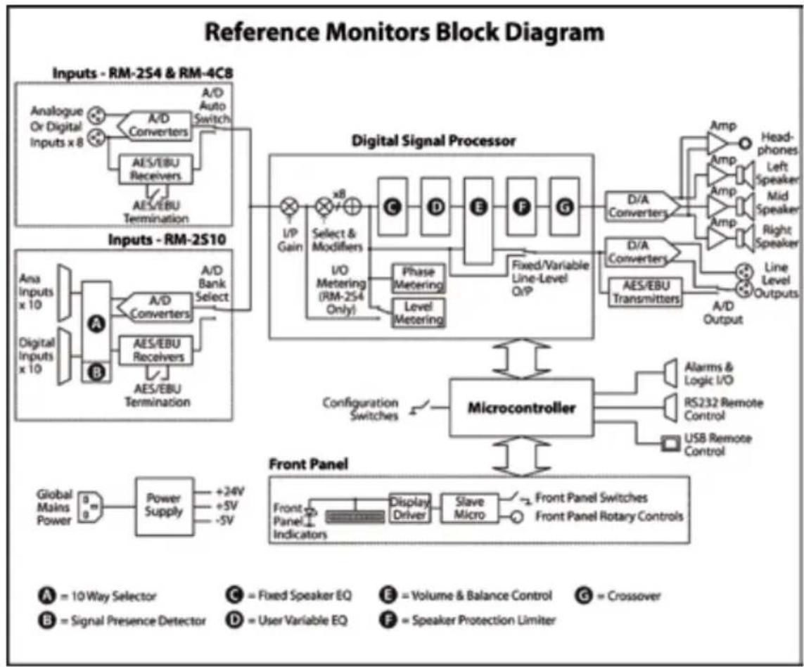
System Block Diagram
flowchart
graph TD
    A["Inputs - RM-2S4 & RM-4C8"] --> B["A/D Auto Switch"]
    B --> C["A/ D Converters"]
    C --> D["AES/EBU Receivers"]
    D --> E["AES/EBU Termination"]
    F["Inputs - RM-2S10"] --> G["A/ D Bank Select"]
    G --> H["A/ D Converters"]
    H --> I["AES/EBU Receivers"]
    I --> J["AES/EBU Termination"]
    K["Digital Signal Processor"] --> L["I/O Metering (RM-2S4 Only)"]
    L --> M["Phase Metering"]
    L --> N["Level Metering"]
    M --> O["C"]
    N --> P["D"]
    O --> Q["E"]
    P --> R["F"]
    Q --> S["G"]
    R --> T["Fixed/Variable Line-Level Q/P"]
    T --> U["A/D Converters"]
    U --> V["D/A Converters"]
    V --> W["AES/EBU Transmitters"]
    W --> X["A/D Output"]
    Y["Microcontroller"] --> Z["Configuration Switches"]
    Z --> AA["Alarms & Logic I/O"]
    Z --> AB["RS232 Remote Control"]
    Z --> AC["USB Remote Control"]
    AD["Front Panel"] --> AE["Front Panel Indicators"]
    AE --> AF["Display Driver"]
    AE --> AG["Slave Micro"]
    AG --> AH["Front Panel Switches"]
    AG --> AI["Front Panel Rotary Controls"]
Fig 1-3: Reference Monitor Block Diagram
Front Panel Indicators & Controls

Fig 1-4: RM-2S4 Front Panel Controls

natural_image
Abstract graphic of two stylized swords with a central circular emblem, set against a blue gradient background (no text or symbols)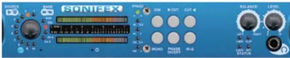
Fig 1-5: RM-2S10 Front Panel Controls
Power LED
The POWER LED illuminates whilst internal power is present within the unit. If this indicator is not on, the most likely reason is simply the absence of mains power, but under fault conditions it may also indicate a ruptured mains fuse or a problem with the internal power supply module.
Rotary Source Selector
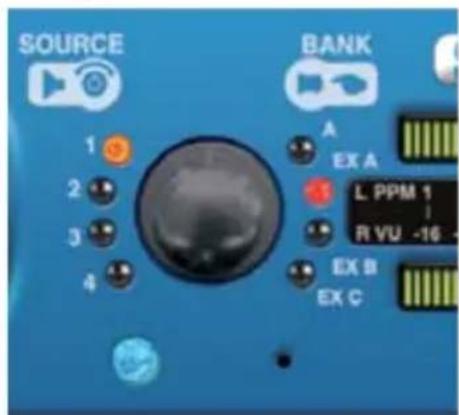
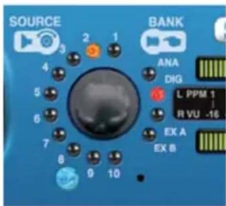
Fig 1-6: RM-2S4 Source Selector Fig 1-7: RM-2S10 Source Selector
The rotary Source selector determines which of the four (RM-2S4) or ten (RM-2S10) stereo audio inputs in the currently selected Bank is routed to the loudspeakers and metering. Turning the selector anticlockwise increments the Source number and vice versa, with the currently selected Source being indicated by illumination of the corresponding Source LED.
The currently selected Source can also be changed by the remote control ports (see the relevant sections of this manual), & such changes will also be reflected by the Source LEDs.
The Source selector is an endless rotary encoder; further rotation will be ignored once the lowest/highest Source has been selected. If the currently selected Bank contains fewer
1
REFERENCE MONITORS RM-2S4 & RM-2S10


natural_image
Abstract graphic of two stylized swords with a circular emblem, set against a blue gradient background (no text or symbols)than four (RM-2S4) or ten (RM-2S10) Sources, it will not be possible to select unimplemented Sources.
When mains power is removed, the currently selected Source is stored in non-volatile memory and recalled instantly once power is restored.
Auto-Selection of Inputs
As standard, the RM-2S4 has auto-selection of the inputs, i.e. whichever analogue or digital signal is connected to the input will be used. There is also an option (in the serial settings) for the RM-2S10 to have auto-selection of it's separate ten analogue inputs in Bank ANA and ten digital inputs in Bank DIG. For users with a smaller number of mixed analogue and digital sources, the auto-selection allows the unit to switch automatically between the analogue and digital banks according to what is connected.
For the RM-2S10, with auto-selection enabled, both the Bank ANA and Bank DIG LEDs are illuminated (expansion banks can still be selected as normal, if fitted). If the current source selection points to a valid digital input then the digital input will be selected. If it does not, the similarly numbered analogue source will be used. If both are present then the digital input takes precedence (hence auto-selection is only useful for a maximum of ten sources). The analogue and digital presence indications are combined (ORed) and displayed simultaneously.
Bank Selector
Pressing the Source selector knob inwards steps sequentially through all available input Banks (groups of stereo inputs). Each press flashes the selected Bank LED and moves the selected Bank onwards by one step. Once the last available Bank is selected, a further press returns the selection to the first available Bank. The currently selected Bank is indicated by illumination of the corresponding Bank LED.
The currently selected Bank may also be changed via the remote control ports (see the appropriate sections of this manual), and such changes will also be reflected by the Bank LEDs.
On the RM-2S4, BANK A corresponds to the four autoselecting (analogue or digital) stereo inputs found on the rear panel, and further Banks become available with the addition of optional expansion cards.
On the RM-2S10, separate Banks are provided for analogue (BANK ANA) and digital (BANK DIG) sources – a total of twenty stereo sources may be attached if both Banks are fully utilised. Further Banks become available with the addition of optional expansion cards. It is not possible to select Banks which are not fitted.
When mains power is removed, the currently selected Bank is stored in non-volatile memory and recalled instantly once power is restored.
Source Presence Indicators (RM-2S10 only)
On the RM-2S10, the presence of active audio on a Source input is indicated by green illumination of the corresponding Source LED. The currently selected Source is indicated by yellow illumination.
This feature may optionally be disabled through the use of the remote control OPT command (see the appropriate section of this manual).
Main Meters
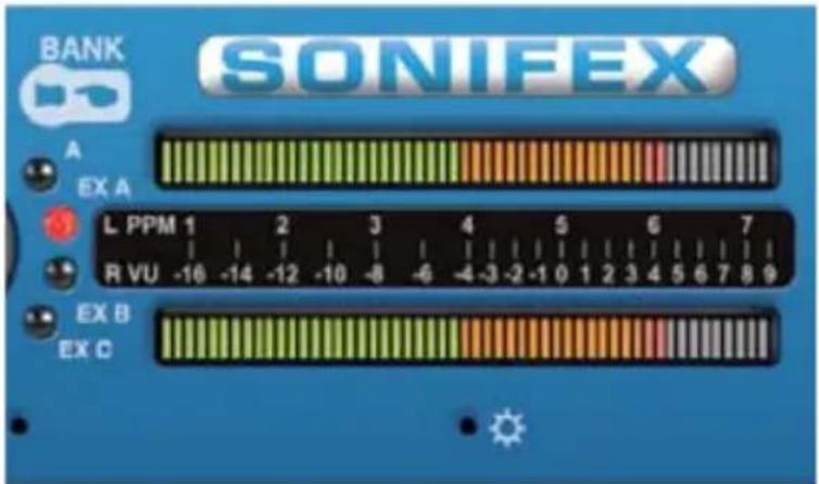
Fig 1-8: RM-2S4 & RM-2S10 Meters
The main meters are twin 53-segment, multicoloured LED bargraphs, displaying the currently selected stereo audio source. The upper meter displays the left channel and the lower meter the right channel.
By default, the meters reflect exactly what is being heard from the loudspeakers including any front panel signal modifiers that are active, i.e. they are "output" meters. For example, if Middle+Side processing is active (see the appropriate section of this manual), the upper meter will display the Middle signal and the lower meter will display the Side. If the CUT modifier is used to mute an input channel, the corresponding meter will display no signal.
If preferred, the meters may be made to behave as "input" meters, i.e. not affected by front panel signal modifiers, through the use of the remote control OPT command (see the appropriate section of this manual).
Several different characteristics are available for the meters to suit different applications and regional preferences. The active meter characteristic is selected by the settings of DIPSwitches 8, 9 and 10 on DIPSwitch Block 1 (found on the underside of the unit), according to the following table.

natural_image
Abstract graphic with two stylized swords and a circular emblem on a blue background (no text or symbols)1
REFERENCE MONITORS RM-2S4 & RM-2S10


natural_image
Abstract graphic of two stylized swords with a circular base, set against a blue background (no text or symbols)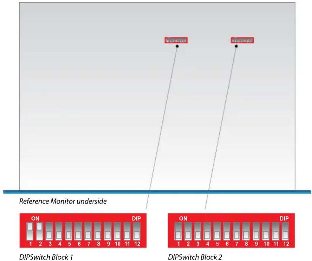
Fig 1-9: RM-2S4 & RM-2S10 DIPSwitch Settings
Note that power should be removed from the unit while making changes to the configuration switches and reapplied once the changes are complete.
| Meter Characteristic | Scale Range* | Amber Section Starts at* | Red Section Starts at* | SW8 | SW9 | SW10 |
| Dual PPM + VU -1 | 3 to +13dBu 0dBu | +8dBu OFF O | FF OFF | |||
| BBC PPM or EBU PPM** | -13 to +13dBu 0dBu | Bu +8dBu ON | OFF OFF | |||
| Nordic PPM -40 to | +12dBu 0dBu +8dBu | Off ON | OFF | |||
| AES Digital PPM -52 to 0dBFS -3dBFS | 0dBFS ON ON | OFF | ON | |||
| DIN PPM | -54 to +5dBu | 0dBu +4dBu | OFF ON | |||
| Standard VU | -24 to +3VU | -4VU | 0VU | ON | OFF | ON |
| Extended VU | -59 to +15VU | -4VU | 0VU | OFF | ON | ON |
| Currently unused – do not select | ON ON | ON | ||||
* With 0dB of input gain selected.
** May be BBC or EBU PPM depending on the choice of scale plate.
Meter Labelling
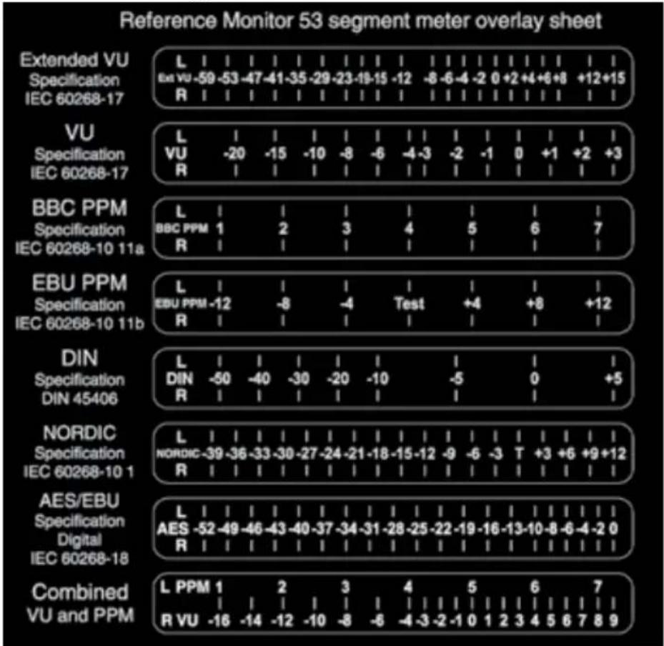
Each meter characteristic possesses different scaling, range and ballistics according to the relevant British or International standards and self-adhesive scales for each of the characteristics are supplied with the unit.
other
Reference Monitor 53 segment meter overlay sheet | Specification | Description | Reference | Value | |---|---|---|---| | Extended VU Specification IEC 60268-17 | L | Exe VU -59 | -59 to -12 | | Extended VU Specification IEC 60268-17 | R | Exe VU -59 to -12 | -59 to -12 | | VU Specification IEC 60268-17 | L | VU -20 | -20 to -3 | | VU Specification IEC 60268-17 | R | VU -20 to -3 | -20 to -3 | | BBC PPM Specification IEC 60268-10 11a | L | BBC PPM 1 | 1 to 4 | | BBC PPM Specification IEC 60268-10 11a | R | BBC PPM 1 to 4 | 1 to 4 | | EBU PPM Specification IEC 60268-10 11b | L | EBU PPM -12 | -8 to -4 | | EBU PPM Specification IEC 60268-10 11b | R | EBU PPM -12 to -8 | -8 to -4 | | DIN Specification DIN 45406 | L | DIN -50 | -50 to -40 | | DIN Specification DIN 45406 | R | DIN -50 to -40 | -50 to -40 | | NORDIC Specification IEC 60268-10 1 | L | NORDIC-39 | -39 to -27 | | NORDIC Specification IEC 60268-10 1 | R | NORDIC-39 to -27 | -39 to -27 | | AES/EBU Specification Digital IEC 60268-18 | L | AES -52 | -52 to -49 | | AES/EBU Specification Digital IEC 60268-18 | R | AES -52 to -49 | -52 to -49 | | Combined VU and PPM | L PPM 1 | R VU -16 | 1 to 7 | | Combined VU and PPM | R VU -16 to -14 | R VU -16 to -14 | 1 to 7 | The chart displays a table with three rows of values: 'L' (Exe VU), 'R' (VU), and 'Test' (Test). The values in the table are explicitly labeled as 'Exe VU' or 'R'. The values in the table represent the absolute magnitude of these residues.Fig 1-10: Meter Labelling Options
Once the desired meter characteristic has been chosen, proper scale labelling may be ensured by removing the appropriate scale from the backing paper and applying it to the recess provided between the two meters.
Brightness Control
The brightness of the bargraph meters and all other front panel indicators may be adjusted to suit user preference or to match similar units nearby.
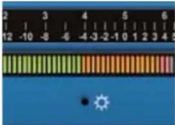
Fig 1-11: Brightness Control
A miniature flat-bladed screwdriver inserted into the hole next to the BRIGHTNESS symbol should be turned clockwise to increase the brightness or anti-clockwise to decrease it.

natural_image
Abstract graphic of two stylized swords with a circular emblem, set against a blue background (no text or symbols)1
REFERENCE MONITORS RM-2S4 & RM-2S10


natural_image
Abstract graphic of two stylized swords with a circular base and grid lines, rendered in blue tones (no text or symbols)PHASE Meter
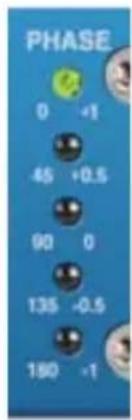
The five-segment LED phase meter indicates the average phase correlation between the left and right channels of the currently selected stereo audio source. It is labelled in both degrees of phase shift and amount of correlation. The phase meter is an “output” meter, reflecting exactly what is being heard from the loudspeakers including any front panel signal modifiers that are active.
A monophonic signal fed to both channels of the selected Source will have a correlation of 1.0, while inverting one such channel – making it perfectly out of phase – gives a correlation of -1.0. True stereo signals will produce a fluctuating phase correlation.
Fig 1-12: Phase Meter Display
An interesting situation arises when only one channel of a stereo source is fed with signal. If the unused channel is perfectly silent (as is possible in the case of a digital source) then the phase correlation will average 0.0, but a small degree of crosstalk between the used and unused channels (as is likely in the case of analogue sources) will allow the signal to self-correlate and the meter will display an average correlation nearer 1.0.
BALANCE Control
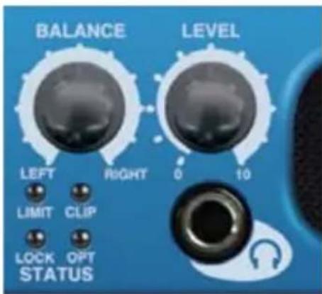
The balance control is a centre-detented rotary potentiometer allowing adjustment of the relative balance between the left and right loudspeakers. The control characteristic maintains a constant overall power from the loudspeakers. Turning the balance control fully to the left increases the volume of the left-hand loudspeaker by 6dB and attenuates the right by 6dB, and vice-versa.
Fig 1-13: Balance Control
LEVEL Control
The LEVEL, or volume, control is a rotary potentiometer allowing volume adjustment of the internal loudspeaker system, the headphone output and optionally the line level outputs (see Line Level Audio Outputs on page 17). A usable control range of 36dB is provided, and with the volume control in the fully anti-clockwise position the signal is completely muted.
High input signal levels and/or high volume settings may result in activation of the loudspeaker protection limiter (refer to the Limiter section of this manual).
Headphone Output
The front panel headphone output is a 14 " (6.35mm) stereo jack socket capable of delivering over 80mW into 32Ω - 600Ω professional headphones at full volume. Higher impedance headphones may be used at reduced levels. Lower impedance headphones should not be used.
Inserting a plug into the headphone socket automatically mutes the internal loudspeakers.
STATUS LED Indicators
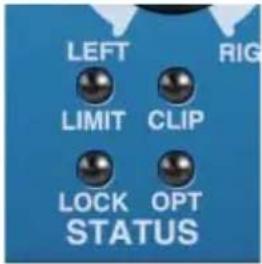
Fig 1-14: Status LEDs
LIMIT indicator
The LIMIT indicator illuminates to show that the loudspeaker protection limiter has been activated. This happens in response to excessive volume levels, which are a product of the input signal level and the setting of the volume control, being requested from the unit and is necessary to prevent permanent damage to the loudspeakers.
The protection limiter is a fast-attack, slow-release type. Brief flashes of the LIMIT indicator on signal peaks are not cause for concern, but significant illumination indicates that the signal is being compressed and that reproduction may be compromised. In those circumstances the setting of the volume control should be reduced.
CLIP indicator
The CLIP indicator illuminates when the signal level of the currently selected source (taking into account any input gain applied – refer to the Inputs section of this manual) has either exceeded or come within 0.5dB of that at which hard clipping occurs.
Analogue input signals will cause clipping if they exceed the maximum acceptable input level (+18dBu with no additional input gain, reducing by 6dB for every 6dB of input gain applied). The only solution is to reduce the input level and/or the amount of input gain being applied; allowing clipping to persist will irreversibly degrade the audio performance.
The digital audio inputs of the RM-2S4 cannot in themselves clip unless extra input gain has been applied, but signal peaks may come within 0.5dB of maximum if the input signal has undergone aggressive processing at an earlier stage, and the CLIP indicator will respond to this.
LOCK indicator
The LOCK indicator illuminates when a valid digital audio signal is present on the currently selected source input. It will not illuminate if the currently selected Source input is an analogue signal, or if a digital audio signal is applied which has a sample rate outside the acceptable range of the unit, contains invalid/non-audio data or is too weak for the receiver to lock on to.
OPT indicator
The OPT indicator is reserved for future use.

natural_image
Abstract graphic of two stylized swords with a circular emblem, set against a blue gradient background (no text or symbols)1
REFERENCE MONITORS RM-2S4 & RM-2S10


natural_image
Abstract graphic with two white swords and a circular emblem on blue background (no text or symbols)Audio Modifiers
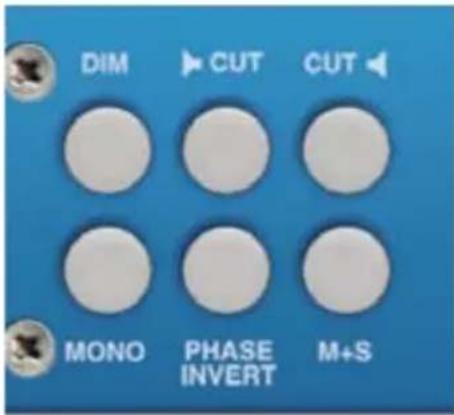
Fig 1-15: RM-2S4 & RM-2S10 Modifier Switches
The audio modifiers are controlled using the 6 white illuminated buttons on the front panel. Each of the modifiers is operated via an illuminated pushbutton switch, with each press of the button toggling the modifier from on to off or vice-versa.
When using the audio modifiers in combination, it is necessary to consider the order in which they are applied since that will affect the results.
The modifiers are applied in the following order (first > last):
Phase invert > Mono > S + D > Dim > Cut L/R
When mains power is removed, the status of the audio modifiers is stored in non-volatile memory and recalled instantly once power is restored.
DIM Audio Modifier
When on, the DIM button is illuminated and the loudspeaker volume level is reduced by 10dB.
The DIM modifier may also be activated by an external signal applied to the rear panel remote control port and the DIM button illuminates when such an external signal is active.
The DIM modifier, unlike the other modifiers, has no effect on the meter readings since it is treated simply as a volume adjustment.
CUT L & CUT R Audio Modifiers
When on, the CUT L and CUT buttons are illuminated and the corresponding channel of the selected audio source is muted.
The CUT L and CUT R modifiers may also be simultaneously activated by an external signal applied to the rear panel remote control port. Both CUT buttons will illuminate when such an external signal is active.
The CUT modifiers will affect the loudspeaker audio, line-level audio outputs, phase meter reading and also, by default, the main meter readings (refer to the Main Meters section of this manual).
MONO Audio Modifier
When on, the MONO button is illuminated and the left and right channels of the currently selected stereo audio source are summed into a monophonic signal prior to further processing and reproduction. Scaling is such that a stereo signal measuring 0dBu on both channels will generate a mono signal measuring 0dBu on both channels.
The MONO modifier will affect the loudspeaker audio, line-level audio outputs, phase meter reading and also, by default, the main meter readings (refer to the Main Meters section of this manual).
PHASE INVERT Audio Modifier
When on, the PHASE INVERT button is illuminated and the right channel of the currently selected stereo audio Source is inverted (phase shifted by 180 degrees) prior to further processing and reproduction.
The PHASE INVERT modifier will affect the loudspeaker audio, line-level audio outputs, phase meter reading and also, by default, the main meter readings (refer to the Main Meters section of this manual).
Being able to invert the polarity of one channel of the monitoring is very useful.
For example, sometimes being able to put the speakers deliberately out of phase is useful to identify the presence of a phase error elsewhere in the signal chain. When trying to match the levels of two channels, such as when aligning a stereo pair, being able to invert one channel and then sum to mono (to produce a cancellation null) makes very fast and easy work of an otherwise fiddly process.
MIDDLE + SIDE (M+S) Audio Modifier
When on, the M+S button is illuminated and the left and right channels of the currently selected stereo audio Source are converted to/from a Middle+Side (also known as Sum+Difference) signal prior to further processing and reproduction. An input signal in standard Left+Right (L+R) format will be encoded into M+S format before metering and reproduction, while an input signal in M+S format will be decoded to L+R. The two processes are identical.
The M+S modifier will affect the loudspeaker audio, line-level audio outputs, phase meter reading and also, by default, the main meter readings (refer to the Main Meters section of this manual).

natural_image
Abstract graphic with two white swords and a circular emblem on blue background (no text or symbols)1
REFERENCE MONITORS RM-2S4 & RM-2S10


natural_image
Abstract graphic with two white swords and a circular emblem on blue background (no text or symbols)Rear Panel Connections & Operation

Fig 1-16: Reference Monitor RM-2S4 Rear

Fig 1-17: Reference Monitor RM-2S10 Rear
Mains Power
Power is applied via a standard three-pin IEC male socket. Mains voltages between 85V and 264V AC and frequencies between 47 and 63Hz are accepted without adjustment. A 2A, 5 x 20mm SB fuse is used. The Earth pin MUST be connected to ensure safety.
Digital Input Termination
Switchable termination is provided to allow the RM-2S4 & RM-2S10 inputs to be bridged across an existing AES/EBU connection without double-termination, but this should only be attempted with the terminating equipment mounted adjacent to the RM-2S4 or RM-2S10 and with connections kept as short as possible.
It is strongly recommended that the digital input termination is set to ON at all times. Failure to do so may result in unreliable reception of digital input signals and/or crosstalk between sources.
Input Gain Adjustment
For both analogue and digital sources the default input gain is zero, i.e. an input of 0dBu results in a reading of 0dBu on the meters. However, to accommodate lower level sources it is possible to introduce extra global input gain in 6dB steps. This gain applies to all inputs and is controlled by the settings of switches 6 and 7 on Block 1 of the configuration switches (found on the underside of the unit), according to the following table. Power should be removed from the unit while making changes to the configuration switches and reapplied once the changes are complete.
| Input Gain | Maximum Signal Level (Analogue Sources) | Maximum Signal Level (Digital Sources) | SW6 SW7 |
| 0dB +18dBu | 0dBFS OFF OFF | ||
| +6dB +12dBu | -6dBFS ON OFF | ||
| +12dB +6dBu | -12dBFS OFF ON | ||
| +18dB 0dBu | -18dBFS ON ON |
Note that the application of extra input gain reduces the maximum signal level permitted before signal clipping occurs. The front panel CLIP indicator illuminates at the onset of clipping, with extended illumination indicating that the input gain should be reduced and/or the input signal levels attenuated.
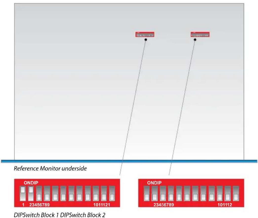
Fig 1-18: RM-2S4 & RM-2S10 DIPswitch Settings
Audio Inputs (RM-2S4)
Three-pin female XLR connectors are provided for the connection of up to four stereo audio sources. Together, these four stereo sources comprise BANK A. The pin assignations are as follows:
Pin 1: Ground
Pin 2: In-phase signal ("hot")
Pin 3: Out-of-phase signal ("cold")
Unbalanced signals may also be used by linking pins 1 and 3 and applying the unbalanced signal to pin 2.
Each of the four source inputs accepts either a pair of analogue line-level signals (using both input XLRs) or a single AES/EBU digital signal (attach to the left-hand XLR of the pair and leave the right-hand XLR unconnected). The RM-2S4 automatically detects digital input signals and seamlessly presents them for selection in exactly the same way as analogue ones; the inputs may therefore be any mixture of analogue and digital sources. A full-scale digital input signal (0dBFS) corresponds to the maximum analogue input signal level of +18dBu (with no extra input gain applied).
110 ohm input termination for the AES/EBU digital inputs is controlled by the settings of switches 1, 2, 11 and 12 on Block 2 of the configuration switches, as follows:

natural_image
Abstract graphic with two white swords and a circular emblem on blue background (no text or symbols)1
REFERENCE MONITORS RM-2S4 & RM-2S10


natural_image
Abstract graphic with two tall white swords and a circular emblem on a blue gradient background (no text or symbols)SW1: When set to ON, digital input 1 is terminated with 110Ω.
SW2: When set to ON, digital input 2 is terminated with 110 .
SW11: When set to ON, digital input 3 is terminated with 110Ω.
SW12: When set to ON, digital input 4 is terminated with 110Ω.
Audio Inputs (RM-2S10)
Three 25-pin female D-type connectors are provided for the simultaneous connection of up to ten stereo analogue (BANK ANA) and ten stereo AES/EBU digital (BANK DIG) audio sources. The pin assignations are as follows:
| Pin No. | Function(BANK DIG 1-10) | Function(BANK ANA 1-5) | Function(BANK ANA 6-10) |
| 1 | AES/EBU Input 1+ Analogue Input | 1L+ Analogue Input 6L+ | |
| 14 | AES/EBU Input 1- Analogue | Input 1L- Analogue Input 6L- | |
| 2 | Ground Ground Ground | ||
| 15 | AES/EBU Input 2- Analogue | Input 1R- Analogue Input 6R- | |
| 3 | AES/EBU Input 2+ Analogue Input | 1R+ Analogue Input 6R+ | |
| 16 | AES/EBU Input 3+ Analogue | Input 2L+ Analogue Input | 7L+ |
| 4 | AES/EBU Input 3- Analogue Input | 2L- Analogue Input 7L- | |
| 17 | Ground Ground Ground | ||
| 5 | AES/EBU Input 4- Analogue Input | 2R- Analogue Input 7R- | |
| 18 | AES/EBU Input 4+ Analogue | Input 2R+ Analogue Input | 7R+ |
| 6 | AES/EBU Input 5+ Analogue Input | 3L+ Analogue Input 8L+ | |
| 19 | AES/EBU Input 5- Analogue | Input 3L- Analogue Input 8L- | |
| 7 | Ground Ground Ground | ||
| 20 | AES/EBU Input 6- Analogue | Input 3R- Analogue Input 8R- | |
| 8 | AES/EBU Input 6+ Analogue Input | 3R+ Analogue Input 8R+ | |
| 21 | AES/EBU Input 7+ Analogue | Input 4L+ Analogue Input | 9L+ |
| 9 | AES/EBU Input 7- Analogue Input | 4L- Analogue Input 9L- | |
| 22 | Ground Ground Ground | ||
| 10 | AES/EBU Input 8- Analogue Input | 4R- Analogue Input 9R- | |
| 23 | AES/EBU Input 8+ Analogue | Input 4R+ Analogue Input | 9R+ |
| 11 | AES/EBU Input 9+ Analogue Input | 5L+ Analogue Input 10L+ | |
| 24 | AES/EBU Input 9- Analogue | Input 5L- Analogue Input | 10L- |
| 12 | Ground Ground Ground | ||
| 25 | AES/EBU Input 10- | Analogue Input 5R- Analogue | Input 10R- |
| 13 | AES/EBU Input 10+ | Analogue Input 5R+ Analogue | Input 10R+ |
Unbalanced signals may also be used by linking the out-of-phase (-) signal pin to Ground and applying the unbalanced signal to the in-phase (+) signal pin.
A full-scale digital input signal (0dBFS) corresponds to the maximum analogue input signal level of +18dBu (with no extra input gain applied).
110 ohm input termination for the AES/EBU digital inputs is controlled by the settings of switches 1 to 10 on the Block 2 of the configuration switches (see Fig 1-17: The RM-2S4 & RM-2S10 DIPswitches), as follows:
SW1: When set to ON, digital input 10 is terminated with 110 Ω.
SW2: When set to ON, digital input 9 is terminated with 110 .
SW3: When set to ON, digital input 8 is terminated with 110 Ω.
SW4: When set to ON, digital input 7 is terminated with 110 Ω.
SW5: When set to ON, digital input 6 is terminated with 110 Ω.
SW6: When set to ON, digital input 5 is terminated with 110 Ω.
SW7: When set to ON, digital input 4 is terminated with 110 Ω.
SW8: When set to ON, digital input 3 is terminated with 110 Ω.
SW9: When set to ON, digital input 2 is terminated with 110 Ω.
SW10: When set to ON, digital input 1 is terminated with 110 Ω.
Line Level Audio Outputs
A pair of three-pin male XLR connectors provides a stereo line-level audio output carrying the selected audio Source signal. The XLR pin assignations are as follows:
Pin 1: Ground
Pin 2: In-phase signal ("hot")
Pin 3: Out-of-phase signal ("cold")
The signals may be unbalanced without loss of level by linking pins 1 and 3 and taking the unbalanced signal from pin 2.
The line-level outputs may be configured either as analogue (using both output XLRs) or AES/EBU digital (attach to the left-hand XLR of the pair and leave the right-hand XLR unconnected). The selection of format is determined by the setting of switches 1-4 in Block 1 of the configuration switches (see Fig 1-17), according to the following table. Switch 5 in the same block determines whether the line-level outputs are fixed in level or proportional in level to the setting of the volume control. Power should be removed from the unit while making changes to the configuration switches and reapplied once the changes are complete.
| Output Format | Output Level SW1 | & 2 SW3 & 4 SW5 | ||
| Analogue Variable | Both ON Both OFF | OFF | ||
| Analogue Fixed B | Both ON Both OFF | ON | ||
| AES/EBU Digital | Variable Both | OFF Both ON | OFF | |
| AES/EBU Digital | Fixed | Both OFF | Both ON | ON |
1
REFERENCE MONITORS RM-2S4 & RM-2S10


natural_image
Abstract graphic with two white stylized swords and a circular emblem on blue background (no text or symbols)The line-level output signals are always affected by the setting of the front-panel audio modifiers, with one exception - DIM only affects the line-level outputs when Variable output level is selected.
Expansion Port
An internal expansion card (RM-HD1 or RM-HDE1) may be fitted to the RM-2S4 or RM-2S10 to increase the number of inputs and/or add to the available functions. Refer to the documentation accompanying the expansion card for details.
Remote Inputs and Outputs
A 15-way male D-type connector carries four open-collector status outputs, four logic-level control inputs plus power and data lines for future expansion. The pin assignations are as follows:
| Pin No. | I/O Function |
| 1 O Audio | under level/fail alarm – latching open collector |
| 9 | MUTE input – pull low to activate |
| 2 O Audio | overlevel alarm – latching open collector |
| 10 | DIM input – pull low to activate |
| 3 O Sustained phase error alarm – latching open collector | |
| 11 | Alarm Reset – pull low to activate |
| 4 O AES/EBU lock output – non-latching open collector | |
| 12 | Not used |
| 5 I Volume control voltage for future use | |
| 13 | Balance control voltage for future use |
| 6 O Fused power for desktop remote control panel | |
| 14 | - Ground |
| 7 O Serial data transmit for future use | |
| 15 | Serial data receive for future use |
| 8 O Serial clock for future use | |
Open-collector outputs are low (conducting) during normal operation. When an alarm occurs they cease conducting and, with the exception of the AES/EBU lock output, remain in that condition until the Alarm Reset input is asserted. Open-collector outputs are rated at 50mA and 30V.
The Audio Overlevel alarm is triggered if either channel of the currently selected input source exceeds +12dBu for longer than 5 seconds.
The Audio Underlevel alarm is triggered if either channel of the currently selected input source remains below -20dBu for longer than 20 seconds.
The Sustained Phase Error alarm is triggered if the phase difference between the two channels of the currently selected input source remains consistently above 90 degrees for longer than 5 seconds.
The AES/EBU Lock output is a real-time (non-latching) status output which becomes active if a valid AES/EBU signal is detected on the currently selected Source input. By default, the open-collector output is low (conducting) when a valid AES signal is detected, but this behaviour may be reversed using the serial remote control LCK: command.
The active-low control inputs all have internal pull-ups. Equipment driving these inputs need sink only 1mA and block 5V.
The MUTE input mutes the loudspeakers and headphones while held low. The front panel CUT L and CUT R buttons illuminate to indicate that MUTE is asserted.
The DIM input reduces the loudspeaker/headphone level by 10dB while held low (for example, whilst an external talkback system is active). The front panel DIM button illuminates to indicate that DIM is asserted.
Asserting the Alarm Reset input by pulling it low resets any active Alarm outputs to their untriggered states and allows them to monitor for new alarm conditions.
RS232 Remote Control
A 9-way female D-type connector carries a standard RS232 interface via which advanced configuration options may be set and many functions may be remotely controlled. The pin assignations are as follows:
Pin 2: Data transmit
Pin 3: Data receive
Pin 5: Ground
All other pins are unused.
The RM-2S4 and RM-2S10 will interface directly with personal computer serial ports at standard RS232 signal levels using a straight-through cable. The data format is 19200 baud with 8 data bits, even parity and 1 stop bit. XON/XOFF flow control is used when necessary.
Sonifex SCi software, when installed on a suitable PC, provides straightforward graphical access to all remote control and configuration options via both RS232 and USB interfaces. Alternatively, commands may be issued from any text-based terminal program (e.g. Hyperterminal) or custom software may be developed for specific requirements.

natural_image
Abstract graphic with two stylized swords and a circular emblem, set against a blue background (no text or symbols)1
REFERENCE MONITORS RM-2S4 & RM-2S10


natural_image
Abstract graphic of two stylized swords with a circular emblem, set against a blue gradient background (no text or symbols)USB Remote Control
A Type B USB socket carries a standard Universal Serial Bus interface via which advanced configuration options may be set and many functions may be remotely controlled.
The RM-2S4 and RM-2S10 will interface directly with personal computer USB ports using a standard USB cable. On first connection, the user will be prompted to install the necessary USB driver (supplied), following which the USB connection behaves as a "virtual serial port" with identical data format and command protocol as the RS232 remote control interface.
Sonifex SCi software, when installed on a suitable PC, provides straightforward graphical access to all remote control and configuration options via both RS232 and USB interfaces. Alternatively, commands may be issued from any text-based terminal program (e.g. Hyperterminal) or custom software may be developed for specific requirements – see the section of this manual on the serial command protocol for further information.
Sonifex SCi software is available free of charge from the sonifex website - www.sonifex.co.uk
Technical Specification RM-2S4 & RM-2S10
Inputs
Audio Inputs (RM-2S4): 4 x stereo analogue or AES/EBU digital (autoselecting)
Audio Inputs (RM-2S10): 10 x stereo analogue, plus 10 x stereo AES/EBU digital
Max Level (0dB Input Gain): +18dBu (analogue)/0dBFS (digital)
CMRR: >60dB typical
Input Impedance: 20kΩ (analogue)
110 Ω (digital with termination switchable)
AES/EBU Sample Rate: 32 to 192kHz, converted internally to 48kHz
Input Gain: 0, +6, +12 or +18dB digital gain (switchable)
Selection: Front panel rotary control with indicator LEDs
Line Level Outputs
Audio Outputs: 1 x stereo analogue or AES/EBU digital (switchable)
Gain re Selected Input: Unity or variable, following volume control (switchable)
Maximum Output Level: +18dBu (analogue)/0dBFS (digital)
Output Impedance: <50 Ω (analogue)/110 Ω (digital)
AES/EBU Sample Rate: 48kHz
Distortion: <0.02% (1kHz, +8dBu output)
Noise: -84dB RMS, unity gain ref +8dBu output
Frequency Response: 20Hz-20kHz +0/-0.5dB
Crosstalk: Analogue I/O, ref 0dBu
1kHz Input: <-90dB
10kHz input: <-85dB
Audio Modifiers
Modifier Selection: Illuminated front panel pushbuttons
DIM: Reduces speaker audio level by 10dB
CUT L & CUT R: Mutes left/right speaker audio
MONO: Combines left and right audio inputs
PHASE INVERT: Inverts phase of right audio input
M+S: Converts stereo input to Middle (sum)
and Side (difference) signals

natural_image
Abstract graphic with two white swords and a circular emblem on blue background (no text or symbols)
natural_image
Abstract graphic with two stylized swords and a circular emblem on a blue background (no text or symbols)User-Variable Equalisation
Type: Parametric
Bands: Five
Centre Frequency: 200Hz to 18kHz
Bandwidth: 0.25 to 2 octaves
Boost/Cut: ±12dB
Programming: Via USB/serial control port
Amplifier/Loudspeakers
Configuration: Three-way with stereo mid/high-frequency drivers & mono low-frequency driver
Power Output: 2 x 5W (HF) + 20W (LF) with protective limiter
Crossover: 500Hz (3rd order Butterworth)
Distortion (HF Outputs): < 0.05% (1kHz, 3W output)
Distortion (LF Output): < 0.05% (100Hz, 6W output)
Noise: More than 80dB below full output
Volume: Mute to full volume via front panel rotary control
Balance Trim: ±6dB via front panel rotary control.
Peak Acoustic Level: 102dB SPL @ 2ft
Level Metering
Number: 2 x 53-segment tri-colour LED bargraphs
Characteristics: Selectable by switch from:
-
Dual BBC PPM + standard VU
-
BBC PPM IEC60268-10 11a
-
EBU PPM IEC60268-10 11b
-
Nordic PPM IEC60268-10 1
-
AES/EBU digital PPM IEC60268-18
-
DIN PPM DIN45406
-
Standard VU IEC60268-17
-
Extended VU IEC60268-17
Ballistics: According to selected characteristic
Line-Up Level: According to selected characteristic
Phase Metering
Type: 5-segment, indication at 0, 45, 90, 135 and 180 degrees
Remote Control
USB: Slave device, 19200 baud
Serial: RS232, 19200 baud, 3-wire connection
Alarm Outputs: 1. Audio underlevel/fail (latching)
- Audio overlevel (latching)
- Sustained phase error (latching)
- AES/EBU input unlock (non-latching)
Open-collector outputs rated at 30V, 50mA maximum
Output low/conducting in normal condition (no alarm)
Control Inputs: 1. Mute audio
- Dim audio
- Alarm reset
Pull-to-ground to activate inputs
Status Indicators
LIMIT: Indicates loudspeaker protection limiter is active.
CLIP: Indicates internal digital clipping due to overlevel.
LOCK: Indicates lock achieved on selected digital input(s).
OPT: For future use.
Connectors
Audio Inputs (RM-2S4): 8 x XLR 3-pin female (balanced, may be unbalanced)
Audio Inputs (RM-2S10): 3 x D-type 25-pin female (balanced, may be unbalanced)
Audio Outputs: XLR 3-pin male (balanced, may be unbalanced)
Headphones: 1/4" (6.35mm) A-gauge 3-pole stereo jack socket
USB: Type B socket
Serial: D-sub 9-pin female
Remote I/O: D-sub 15-pin male
Mains Input: Filtered 3-pin IEC male, continuously rated 85 - 264VAC, 47 - 63Hz, fused 2A, 60W peak, 30W average

natural_image
Abstract graphic of two stylized swords with a circular emblem, set against a blue gradient background (no text or symbols)1
REFERENCE MONITORS RM-2S4 & RM-2S10


natural_image
Abstract graphic of two stylized swords with a circular base and grid pattern (no text or symbols)DIP Switch Settings (Underneath The Unit, See Fig 1-17)
Block 1 (RM-2S4 & RM-2S10)
SW1 Audio Output Analogue ON Digital OFF
SW2 Audio Output Analogue ON Digital OFF
SW3 Audio Output Digital ON Analogue OFF
SW4 Audio Output Digital ON Analogue OFF
SW5 Output Level Fixed ON Variable OFF
SW6 Input Gain Matrix
SW7 Input Gain Matrix
SW8 Meter Ballistics & Scaling Matrix
SW9 Meter Ballistics & Scaling Matrix
SW10 Meter Ballistics & Scaling Matrix
SW11 Unused Set to OFF
SW12 Firmware Update Force Bootload ON Normal Operation OFF
Block 2 (RM-2S4)
SW1 Digital Input Termination Input 1 110Ω ON Unterminated OFF
SW2 Digital Input Termination Input 2 110Ω ON Unterminated OFF
SW3-SW10 Unused
SW11 Digital Input Termination Input 3 110Ω ON Unterminated OFF
SW12 Digital Input Termination Input 4 110Ω ON Unterminated OFF
Block 2 (RM-2S10)
SW1 Digital Input Termination Input 10 110Ω ON Unterminated OFF
SW2 Digital Input Termination Input 9 110Ω ON Unterminated OFF
SW3 Digital Input Termination Input 8 110Ω ON Unterminated OFF
SW4 Digital Input Termination Input 7 110Ω ON Unterminated OFF
SW5 Digital Input Termination Input 6 110Ω ON Unterminated OFF
SW6 Digital Input Termination Input 5 110Ω ON Unterminated OFF
SW7 Digital Input Termination Input 4 110Ω ON Unterminated OFF
SW8 Digital Input Termination Input 3 110Ω ON Unterminated OFF
SW9 Digital Input Termination Input 2 110Ω ON Unterminated OFF
SW10 Digital Input
Termination Input 1 110Ω ON Unterminated OFF
SW11 Unused Set to OFF
SW12 Unused Set to OFF
Equipment Type
RM-2S4 Reference Monitor, 2 LED meters, 4 stereo channel inputs
RM-2S10 Reference Monitor, 2 LED meters, 10 stereo channel inputs
Physical Specification
Dimensions (Raw): 48cm (W) x 30.5cm (D) x 4.4cm (H) (1U)
HD-SDI expansion card

natural_image
Abstract graphic with two vertical bars and a circular emblem, set against a blue gradient background (no text or symbols)2
REFERENCE MONITORS RM-4C8


natural_image
Abstract graphic of two stylized swords with a circular base, set against a blue background (no text or symbols)RM-4C8 Reference Monitor, 4 LED meters, 8 channel inputs & dual selectors
Introduction

natural_image
Blue electronic circuit board with various components and connectors (no visible text or symbols)Fig 2-1: RM-4C8 Reference Monitor Front Panel
The RM-4C8 is a 1U rack-mount unit offering quality loudspeaker monitoring and accurate, high-resolution metering of up to eight mono audio sources and more with the addition of an optional expansion card. Sources may be in any mixture of analogue and AES/EBU digital formats, with sample rates up to 192kHz accepted.
The Sources for both left- and right-hand loudspeakers (and additional Banks of Sources, if available) are individually selected via a pair of front panel rotary encoders, with clear LED indication of the current selections. A pair of line-level audio outputs, configurable as analogue or AES/EBU digital, follow the selected sources at either a fixed level or one mirroring the loudspeaker volume.
The levels of the selected bank of four sources are simultaneously displayed on a quartet of bright, multicoloured 26-segment bargraph meters, with a choice of seven accurately modelled scales/responses to suit different applications and local preferences. A separate phase meter indicates channel correlation or phase error conditions between the two selected sources. On the rear panel, open-collector alarm outputs provide hardware indication of sustained underlevel, overlevel, phase errors and digital source lock.
Six illuminated pushbuttons provide access to a range of audio ‘modifiers’ – instant dimming of the volume, muting of each audio channel, stereo-to-mono conversion, phase inversion and Middle+Side transcoding. On the rear panel, logic-level inputs allow direct remote access to the DIM and MUTE functions.
The three-way loudspeaker system is fed via a DSP-based active crossover and a trio of highly efficient Class-D amplifiers. Careful attention to driver selection, materials and case design, plus active DSP equalisation, has ensured a flat response and outstanding reproduction from such a shallow unit. A protective limiter prevents damage to the loudspeakers under overload conditions and the front-panel headphone socket automatically mutes the internal loudspeakers when a plug is inserted. A Balance control allows you to alter the stereo image, or Pan, of the two selected sources.
A further five-band parametric equaliser can be accessed for room-equalisation purposes via Sonifex SCi Windows-based remote control software. Source selection, status monitoring and unit ID functions, plus firmware updates to add extra functionality, are all accessible remotely via both USB and RS232 connections in conjunction with Sonifex SCi software. The open control protocol also allows operation with terminal programs or customised applications.
Optional additions to the RM-4C8 include HD video input expansion cards, allowing multiple AES groups embedded within an HD-SDI or SD-SDI signal to be de-embedded and monitored, either with Dolby E and Dolby Digital decoding (RM-HDE1) or without (RM-HD1).
The RM-4C8 operates from global mains voltages (85-264V AC, 47-63Hz) without adjustment.
System Block Diagram
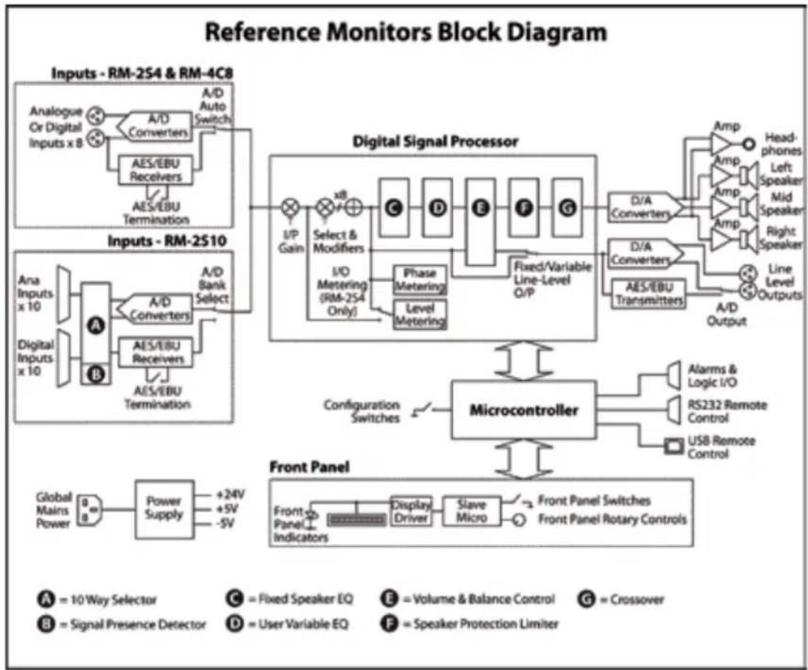
flowchart
graph TD
    A["Inputs - RM-2S4 & RM-4C8"] --> B["A/D Auto Switch"]
    B --> C["Analogue Or Digital Inputs x 8"]
    C --> D["A/D Converters"]
    D --> E["AES/EBU Receivers"]
    E --> F["AES/EBU Termination"]
    G["Inputs - RM-2S10"] --> H["A/B Bank Select"]
    H --> I["A/D Converters"]
    I --> J["AES/EBU Receivers"]
    J --> K["AES/EBU Termination"]
    L["Digital Signal Processor"] --> M["xB Gain"]
    M --> N["Select & Modifiers"]
    N --> O["I/O Metering (RM-2S4 Only)"]
    O --> P["Phase Metering"]
    P --> Q["Level Metering"]
    Q --> R["Fixed/Variable Line-Level O/P"]
    S["Microcontroller"] --> T["Configuration Switches"]
    T --> U["Alarms & Logic I/O"]
    T --> V["RS232 Remote Control"]
    T --> W["USB Remote Control"]
    X["Front Panel"] --> Y["Display Driver"]
    Y --> Z["Slave Micro"]
    Z --> AA["Front Panel Switches"]
    Z --> AB["Front Panel Rotary Controls"]
Fig 2-2: Reference Monitor Block Diagram

natural_image
Abstract graphic with two white swords and a circular emblem on blue background (no text or symbols)2
REFERENCE MONITORS RM-4C8


natural_image
Abstract graphic with two stylized white swords and a circular emblem on blue background (no text or symbols)Front Panel Indicators & Controls
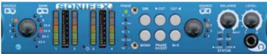
Fig 2-3: RM-4C8 Front Panel Controls
Power LED
The POWER LED illuminates whilst internal power is present within the unit. If this indicator is not on, the most likely reason is simply the absence of mains power, but under fault conditions it may also indicate a ruptured mains fuse or a problem with the internal power supply module.
Rotary Source Selectors
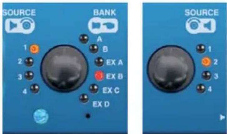
Fig 2-4: RM-4C8 Rotary Source Selectors
The two rotary Source selectors determine which of the four audio inputs in the currently selected Bank is routed to each loudspeaker. To increment the Source number, the left-hand selector should be turned anticlockwise and the right-hand selector clockwise; rotation in the opposite direction decrements the Source number. The currently selected Sources are indicated by illumination of the corresponding Source LEDs.
The currently selected Sources may also be changed via the remote control ports, using the Sonifex SCi software and such changes will also be reflected by the Source LEDs.
The Source selectors are endless rotary encoders; further rotation once the lowest/highest Source has been selected will be ignored. If the currently selected Bank contains fewer than four Sources, it will not be possible to select unimplemented Sources.
When mains power is removed, the currently selected Sources are stored in non-volatile memory and recalled instantly once power is restored.
Auto-Selection of Inputs
As standard, the RM-4C8 has auto-selection of the inputs, i.e. whichever analogue or digital signal is connected to the input will be used.
Bank Selector
Pressing the left-hand Source selector knob inwards steps sequentially through all available input Banks (groups of four inputs). Each press moves the selected Bank onwards by one step; once the last available Bank is selected, a further press returns the selection to the first available Bank. The currently selected Bank is indicated by illumination of the corresponding Bank LED. The currently selected Bank may also be changed via the remote control ports (see the appropriate sections of this manual), and such changes will also be reflected by the Bank LEDs.
As standard, the RM-4C8 possesses two Banks, A and B. Both comprise four monophonic Sources, each of which may be a mono analogue signal, part of a stereo analogue signal, part of a stereo AES/EBU digital signal or any combination thereof. Attaching a valid AES/EBU digital signal automatically assigns its two channels to a pair of Sources. Further Banks become available with the addition of optional expansion cards. It is not possible to select Banks which are not fitted.
When mains power is removed, the currently selected Bank is stored in non-volatile memory and recalled instantly once power is restored.
Main Meters
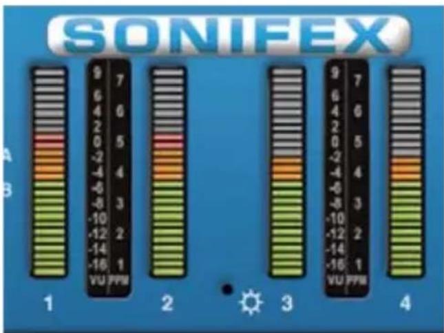
Fig 2-5: RM-4C8 Meters
The main meters are quad 26-segment, multicoloured LED bargraphs, displaying the four Sources in the currently selected Bank.
The meters behave as "input" meters, i.e. they are not affected by front panel signal Modifiers such as Middle+Side or Cut.
Several different characteristics are available for the meters to suit different applications and regional preferences. The active meter characteristic is selected by the settings of DIPSwitches 8, 9 and 10 on DIPSwitch Block 1 (found on the underside of the unit), according to the following table.

natural_image
Abstract graphic with two stylized swords and a circular emblem, set against a blue gradient background (no text or symbols)2
REFERENCE MONITORS RM-4C8


natural_image
Abstract graphic with two white stylized swords and a circular emblem, set against a blue gradient background (no text or symbols)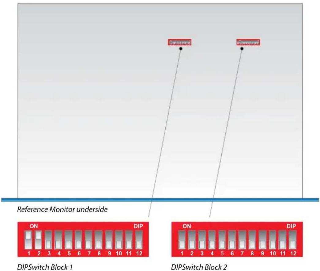
Fig 2-6: RM-4C8 DIPSwitch Settings
Note that power should be removed from the unit while making changes to the configuration switches and reapplied once the changes are complete.
| Meter Characteristic | Scale Range* | Amber section starts at* | Red section starts at* | SW8 | SW9 | SW10 |
| Dual PPM + VU -12 to | +13dBu 0dBu +8 | dBu OFF OFF | OFF | |||
| BBC PPM or EBU PPM** | -12 to +13dBu 0 | dBu +8dBu | ON OFF OFF | |||
| Nordic PPM -38 to +12 | dBu 0dBu +8dBu | OFF ON OFF | ||||
| AES Digital PPM -50 to | 0dBFS -2dBFS 0 | dBFS ON ON | OFF | |||
| DIN PPM -50 to +5dBu | 0dBu +4dBu OFF | OFF ON | ||||
| Standard VU | -22 to +3VU | -4VU | 0VU | ON | OFF | ON |
| Extended VU | -55 to +15VU -3VU | +1VU OFF ON | ON | |||
| Currently unused – do not select | ON ON ON | |||||
* With 0dB of input gain selected.
** May be BBC or EBU PPM depending on choice of scale plate.
Meter Labelling
Each meter characteristic possesses different scaling, range and ballistics according to the relevant British or International standards and self-adhesive scales for each of the characteristics are supplied with the unit.
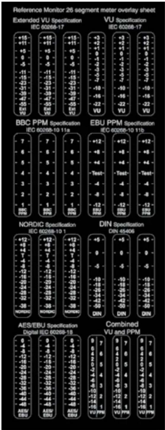
other
Reference Monitor 26 segment meter overlay sheet | Specification | Specification | Value | | :--- | :--- | :--- | | +15 | IEC 60268-17 | -15 | | +11 | IEC 60268-17 | -11 | | +5 | IEC 60268-17 | +5 | | 0 | IEC 60268-17 | 0 | | -5 | IEC 60268-17 | -5 | | -11 | IEC 60268-17 | -11 | | -15 | IEC 60268-17 | -15 | | -23 | IEC 60268-17 | -23 | | -31 | IEC 60268-17 | -31 | | -38 | IEC 60268-17 | -39 | | -47 | IEC 60268-17 | -47 | | -55 | IEC 60268-17 | -55 | | Ext YU | IEC 60268-17 | Ext YU | | +15 | IEC 60268-17 | +15 | | +11 | IEC 60268-17 | +11 | | +5 | IEC 60268-17 | +5 | | 0 | IEC 60268-17 | 0 | | -5 | IEC 60268-17 | -5 | | -11 | IEC 60268-17 | -11 | | -15 | IEC 60268-17 | -23 | | -23 | IEC 60268-17 | -31 | | -31 | IEC 60268-17 | -39 | | -38 | IEC 60268-17 | -47 | | -47 | IEC 60268-17 | -55 | | Ext YU | IEC 60268-17 | Ext YU | | +3 | IEC 60268-17 | +3 | | +2 | IEC 60268-17 | +2 | | +1 | IEC 60268-17 | 0 | | 0 | IEC 60268-17 | -1 | | -1 | IEC 60268-17 | -2 | | -3 | IEC 60268-17 | -3 | | -5 | IEC 60268-17 | -5 | | -7 | IEC 60268-17 | -7 | | -10 | IEC 60268-17 | -10 | | -16 | IEC 60268-17 | -16 | | -22 | IEC 60268-17 | -22 | | VU | IEC 60268-17 | VU | BBC PPM Specification: IEC 60268-10 11a; EBU PPM Specification: IEC 60268-10 11b; NORDIC Specification: IEC 60268-10 1; DIN Specification: DIN 45406; AES/EBU Specification: Digital IEC 60268-18; Combined VU and PPM: VU PPMFig 2-7: Meter Labelling Options
Once the desired meter characteristic has been chosen, proper scale labelling may be ensured by removing the appropriate scales from the backing paper and applying them to the recesses provided between the meters.

natural_image
Abstract graphic with two white swords and a circular emblem on blue background (no text or symbols)2
REFERENCE MONITORS RM-4C8


natural_image
Abstract graphic with two tall white swords and a circular emblem, set against a blue background (no text or symbols)Brightness Control
The brightness of the bargraph meters and all other front panel indicators may be adjusted to suit user preference or to match similar units nearby.
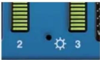
natural_image
Blue electronic device with two vertical strips and a sun icon, no readable text or symbolsFig 2-8: Brightness Control
A miniature flat-bladed screwdriver inserted into the hole marked BRIGHTNESS should be turned clockwise to increase the brightness or anti-clockwise to decrease.
PHASE Meter
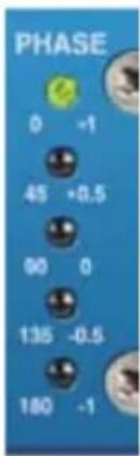
The five-segment LED phase meter indicates the average phase correlation between the two currently selected audio Sources. It is labelled in both degrees of phase shift and amount of correlation. The phase meter is an "output" meter, reflecting exactly what is being heard from the loudspeakers including any front panel signal Modifiers that are active.
If both selected Sources carry the same signal, a correlation of 1.0 will result, while inverting one channel – making it perfectly out of phase – gives a correlation of -1.0. True stereo signals will produce a fluctuating phase correlation.
Fig 2-9: Phase Meter Display
An interesting situation arises when only one of the selected Sources is fed with signal. If the unused channel is perfectly silent (as is possible in the case of a digital source) then the phase correlation will average 0.0, but a small degree of crosstalk between the used an unused channels (as is likely in the case of analogue sources) will allow the signal to self-correlate and the meter will display an average correlation nearer 1.0.
BALANCE Control
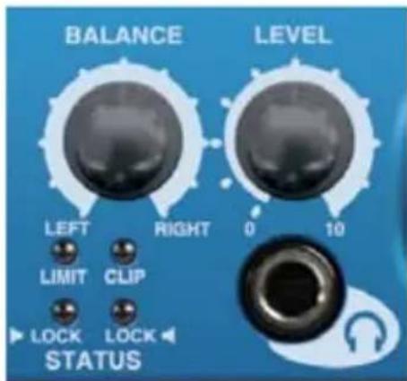
Fig 2-10: Balance Control
The balance control is a centre-detented rotary potentiometer allowing adjustment of the relative balance between the left and right loudspeakers. The control characteristic maintains a constant overall power from the loudspeakers. turning the balance control fully to the left increases the volume of the left-hand loudspeaker by 6dB and attenuates the right by 6dB, and vice-versa.
LEVEL Control
The LEVEL, or volume, control is a rotary potentiometer allowing volume adjustment of the internal loudspeaker system, the headphone output and optionally the line level outputs (see Line Level Audio Outputs on page 37). A usable control range of 36dB is provided, and with the volume control in the fully anti-clockwise position the signal is completely muted.
High input signal levels and/or high volume settings may result in activation of the loudspeaker protection limiter (refer to the Limiter section of this manual).
Headphone Output
The front panel headphone output is a 14 " (6.35mm) stereo jack socket capable of delivering over 80mW into 32Ω - 600Ω professional headphones at full volume. Higher impedance headphones may be used at reduced levels. Lower impedance headphones should not be used.
Inserting a plug into the headphone socket automatically mutes the internal loudspeakers.
STATUS LED Indicators
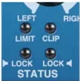
Fig 2-11: Status LEDs
LIMIT indicator
The LIMIT indicator illuminates to show that the loudspeaker protection limiter has been activated. This happens in response to excessive volume levels – which are a product of input signal level and the setting of the volume control – being requested from the unit and is necessary to prevent permanent damage to the loudspeakers.
The protection limiter is a fast-attack, slow-release type. Brief flashes of the LIMIT indicator on signal peaks are not cause for concern, but significant illumination indicates that the signal is being compressed and that reproduction may be compromised. In those circumstances the setting of the volume control should be reduced.
CLIP indicator
The CLIP indicator illuminates when the signal level of either currently selected Source (taking into account any input gain applied – refer to the Inputs section of this manual) has exceeded or come within 0.5dB of that at which hard clipping occurs.
Analogue input signals will cause clipping if they exceed the maximum acceptable input level (+18dBu with no additional input gain, reducing by 6dB for every 6dB of input gain applied). The only solution is to reduce the input level and/or the amount of input gain being applied; allowing clipping to persist will irreversibly degrade the audio performance.

natural_image
Abstract graphic with two white swords and a circular emblem, set against a blue gradient background (no text or symbols)2
REFERENCE MONITORS RM-4C8


natural_image
Abstract graphic of two stylized swords with a central emblem, set against a blue and white background (no text or symbols)The digital audio inputs of the RM-4C8 cannot in themselves clip unless extra input gain has been applied, but signal peaks may come within 0.5dB of maximum if the input signal has undergone aggressive processing at an earlier stage, and the CLIP indicator will respond to this.
LOCK L and LOCK R indicators
The LOCK indicators illuminate when a valid digital audio signal is present on the corresponding currently selected Source input. They will not illuminate if the currently selected Source input is an analogue signal, or if a digital audio signal is applied which has a sample rate outside the acceptable range of the unit, contains invalid/non-audio data or is too weak for the receiver to lock on to.
Audio Modifiers
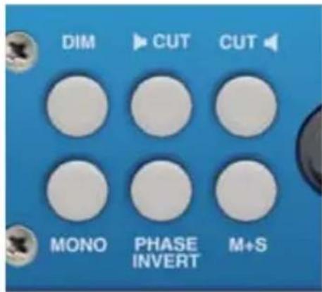
Fig 2-12: RM-4C8 Modifier Switches
The audio modifiers are controlled using the 6 white illuminated buttons on the front panel. Each of the modifiers is operated via an illuminated pushbutton switch, with each press of the button toggling the modifier from on to off or vice-versa.
When using the audio modifiers in combination, it is necessary to consider the order in which they are applied since that will affect the results.
The modifiers are applied in the following order (first > last):
Phase invert > Mono > S + D > Dim > Cut L/R
When mains power is removed, the status of the audio modifiers is stored in non-volatile memory and recalled instantly once power is restored.
DIM Audio Modifier
When on, the button is illuminated and the loudspeaker volume level is reduced by 10dB.
The DIM modifier may also be activated by an external signal applied to the rear panel remote control port. The DIM button will illuminate when such an external signal is active.
CUT L & CUT R Audio Modifiers
When on, the button is illuminated and the corresponding loudspeaker channel is muted.
The CUT L and CUT R modifiers may also be simultaneously activated by an external signal applied to the rear panel remote control port. Both CUT buttons will illuminate when such an external signal is active.
The CUT modifiers will affect the loudspeaker audio, line-level audio outputs and phase meter reading.
MONO Audio Modifier
When on, the button is illuminated and the two currently selected audio Source signals are summed into a monophonic signal prior to further processing and reproduction. Scaling is
such that two selected Sources each measuring 0dBu will deliver a mono signal measuring 0dBu to both channels.
The MONO modifier will affect the loudspeaker audio, line-level audio outputs and phase meter reading.
PHASE INVERT Audio Modifier
When on, the button is illuminated and the selected right-hand Source signal is inverted (phase shifted by 180 degrees) prior to further processing and reproduction.
The PHASE INVERT modifier will affect the loudspeaker audio, line-level audio outputs and phase meter reading.
MIDDLE + SIDE (M+S) Audio Modifier
When on, the button is illuminated and the currently selected Source signals are converted to/from Middle+Side (also known as Sum+Difference) format prior to further processing and reproduction. Input signals in standard Left+Right (L+R) format will be encoded into M+S format before reproduction, while input signals in M+S format will be decoded to L+R – the two processes are identical.
The M+S modifier will affect the loudspeaker audio, line-level audio outputs and phase meter reading.

natural_image
Abstract graphic of two stylized swords with a central emblem, set against a blue gradient background (no text or symbols)2
REFERENCE MONITORS RM-4C8


natural_image
Abstract graphic with two tall white swords and a circular emblem on a blue background (no text or symbols)Rear Panel Connections & Operation

Fig 2-13: RM-4C8 Rear
Mains Power
Power is applied to the unit via a standard three-pin IEC male socket. Mains voltages between 85 and 264V AC and frequencies between 47 and 63Hz are accepted without adjustment.
The Earth pin MUST be connected to ensure safety.
Digital Input Termination
Switchable termination is provided to allow the RM-4C8 inputs to be bridged across an existing AES/EBU connection without double-termination, but this should only be attempted with the terminating equipment mounted adjacent to the RM-4C8 and with connections kept as short as possible.
It is strongly recommended that the digital input termination is set to ON at all times. Failure to do so may result in unreliable reception of digital input signals and/or crosstalk between Sources.
110 ohm input termination for the AES/EBU digital inputs is controlled by the settings of switches 1, 2, 11 and 12 on Block 2 of the configuration switches (see Fig 2-6: The RM-4C8 DIPSwitch Settings), as follows:
SW1: When set to ON, digital input A1/2 is terminated with 110Ω.
SW2: When set to ON, digital input A3/4 is terminated with 110Ω.
SW11: When set to ON, digital input B1/2 is terminated with 110Ω.
SW12: When set to ON, digital input B3/4 is terminated with 110Ω.
Input Gain Adjustment
For both analogue and digital Sources the default input gain is zero, i.e. an input of 0dBu results in a reading of 0dBu on the meters. However, to accommodate lower level sources it is possible to introduce extra global input gain in 6dB steps. This gain applies to all inputs and is controlled by the settings of switches 6 and 7 on the right-hand block of configuration switches (found on the underside of the unit), according to the following table. Power should be removed from the unit while making changes to the configuration switches and reapplied once the changes are complete.
| Input Gain Maximum Signal Level (Analogue Sources) | Maximum Signal Level (Digital Sources) | SW6 SW7 |
| 0dB +18dBu 0dBFS OFF OFF | ||
| +6dB +12dBu -6dBFS ON OFF | ||
| +12dB +6dBu -12dBFS OFF ON | ||
| +18dB 0dBu -18dBFS | ON ON |
Note that the application of extra input gain reduces the maximum signal level permitted before signal clipping occurs. The front panel CLIP indicator illuminates at the onset of clipping, with extended illumination indicating that the input gain should be reduced and/or the input signal levels attenuated.
Audio Inputs
Three-pin female XLR connectors are provided for the connection of up to eight balanced audio Sources in two Banks (A and B) of four. The pin assignations are as follows:
Pin 1: Ground
Pin 2: In-phase signal ("hot")
Pin 3: Out-of-phase signal ("cold")
Unbalanced signals may also be used by linking pins 1 and 3 and applying the unbalanced signal to pin 2.
Each Source input accepts an analogue line-level signal, which may be a complete monophonic signal or one half of a stereo pair. Two of the four XLRs in each Bank also accept AES/EBU digital signals, the two channels of which are automatically routed to a pair of Source channels as per the connector labelling.
The RM-4C8 automatically detects digital input signals and seamlessly presents them for selection in exactly the same way as analogue ones; the inputs may therefore be any mixture of analogue and digital Sources. A full-scale digital input signal (0dBFS) corresponds to the maximum analogue input signal level of +18dBu (with no extra input gain applied).
Line Level Audio Outputs
A pair of three-pin male XLR connectors provides a stereo line-level audio output carrying the selected audio Source signals. The XLR pin assignations are as follows:
Pin 1: Ground
Pin 2: In-phase signal ("hot")
Pin 3: Out-of-phase signal ("cold")
The signals may be unbalanced without loss of level by linking pins 1 and 3 and taking the unbalanced signal from pin 2.
The line-level outputs may be configured either as analogue (using both output XLRs) or AES/EBU digital (attach to the left-hand XLR of the pair and leave the right-hand XLR unconnected). The selection of format is determined by the setting of switches 1-4 in Block 1 of the configuration switches (see Fig 2-6), according to the following table. Switch 5 in the same block determines whether the line-level outputs are fixed in level or proportional in level to the setting of the volume control. Power should be removed from the unit while making changes to the configuration switches and reapplied once the changes are complete.

natural_image
Abstract graphic with two stylized swords and a circular emblem, set against a blue background (no text or symbols)2
REFERENCE MONITORS RM-4C8


natural_image
Abstract graphic of two stylized swords with a circular base and grid pattern (no text or symbols)| Output Format Output | Level SW1 & 2 SW3 & 4 SW5 | ||
| Analogue Variable Both | ON Both OFF OFF | ||
| Analogue Fixed Both ON | Both OFF ON | ||
| AES/EBU Digital Variable | Both OFF Both ON OFF | ||
| AES/EBU Digital Fixed | Both OFF Both ON | ON | ON |
The line-level output signals are always affected by the setting of the front-panel audio Modifiers, with one exception - DIM only affects the line-level outputs when Variable output level is selected.
Expansion Port
An internal expansion card (RM-HD1 or RM-HDE1) may be fitted to the RM-4C8 to increase the number of inputs and/or add to the available functions. Refer to Section 3 of this handbook for details.
Remote Inputs and Outputs
A 15-way male D-type connector carries four open-collector status outputs, four logic-level control inputs plus power and data lines for future use. The pin assignations are as follows:
| Pin No. | I/O | Function |
| 1 | O | Audio underlevel/fail alarm – latching open collector |
| 9 | I | MUTE input – pull low to activate |
| 2 | O | Audio overlevel alarm – latching open collector |
| 10 | I | DIM input – pull low to activate |
| 3 | O | Sustained phase error alarm – latching open collector |
| 11 | I | Alarm Reset – pull low to activate |
| 4 | O | AES/EBU lock output – non-latching open collector |
| 12 | I | Not used |
| 5 | I | Volume control voltage for future use |
| 13 | I | Balance control voltage for future use |
| 6 | O | Fused power for desktop remote control panel |
| 14 | - | Ground |
| 7 | O | Serial data transmit for future use |
| 15 | I | Serial data receive for future use |
| 8 | O | Serial clock for future use |
Open-collector outputs are low (conducting) during normal operation. When an alarm occurs they cease conducting and, with the exception of the AES/EBU lock output, remain in that condition until the Alarm Reset input is asserted. Open-collector outputs are rated at 50mA and 30V.
The Audio Overlevel alarm is triggered if either currently selected input Source exceeds +12dBu for longer than 5 seconds.
The Audio Underlevel alarm is triggered if either currently selected input Source remains below -20dBu for longer than 20 seconds.
The Sustained Phase Error alarm is triggered if the phase difference between the two currently selected input Sources remains consistently above 90 degrees for longer than 5 seconds.
The AES/EBU Lock output is a real-time (non-latching) status output which becomes active if a valid AES/EBU signal is detected. By default, the open-collector output is low (conducting) when a valid AES signal is detected on either of the currently selected Source inputs. However, the polarity of the output may be reversed and/or a requirement imposed that a valid signal be present on both currently selected Source inputs using the serial remote control LCK: command.
The active-low control inputs all have internal pull-ups. Equipment driving these inputs need sink only 1mA and block 5V.
The MUTE input mutes the loudspeakers and headphones while held low. The front panel CUT L and CUT R buttons illuminate to indicate that MUTE is asserted.
The DIM input reduces the loudspeaker/headphone level by 10dB while held low (for example, whilst an external talkback system is active). The front panel DIM button illuminates to indicate that DIM is asserted.
Asserting the Alarm Reset input by pulling it low resets any active Alarm outputs to their untriggered states and allows them to monitor for new alarm conditions.
RS232 Remote Control
A 9-way female D-type connector carries a standard RS232 interface via which advanced configuration options may be set and many functions may be remotely controlled. The pin assignations are as follows:
Pin 2: Data transmit
Pin 3: Data receive
Pin 5: Ground
All other pins are unused.
The RM-4C8 will interface directly with personal computer serial ports at standard RS232 signal levels using a straight-through cable. The data format is 19200 baud with 8 data bits, even parity and 1 stop bit. XON/XOFF flow control is used when necessary.
Sonifex SCi software, when installed on a suitable PC, provides straightforward graphical access to all remote control and configuration options via both RS232 and USB interfaces. Alternatively, commands may be issued from any text-based terminal program (e.g. Hyperterminal) or custom software may be developed for specific requirements.

natural_image
Abstract graphic with two stylized swords and a circular emblem, set against a blue background (no text or symbols)2
REFERENCE MONITORS RM-4C8


natural_image
Abstract graphic of two stylized swords with a circular emblem, set against a blue gradient background (no text or symbols)USB Remote Control
A Type B USB socket carries a standard Universal Serial Bus interface via which advanced configuration options may be set and many functions may be remotely controlled.
The RM-4C8 will interface directly with personal computer USB ports using a standard USB cable. On first connection, the user will be prompted to install the necessary USB driver (supplied), following which the USB connection behaves as a "virtual serial port" with identical data format and command protocol as the RS232 remote control interface.
Sonifex SCi software, when installed on a suitable PC, provides straightforward graphical access to all remote control and configuration options via both RS232 and USB interfaces. Alternatively, commands may be issued from any text-based terminal program (e.g. Hyperterminal) or custom software may be developed for specific requirements – see the section of this manual on the serial command protocol for further information.
Sonifex SCi software is available free of charge from the sonifex website - www.sonifex.co.uk
Technical Specification RM-4C8
Inputs
Number of Channels: 8 x analogue or AES/EBU digital inputs (autoselecting).
Max Level (0dB Input Gain): +18dBu (analogue)/0dBFS (digital).
CMRR: >60dB typical
Input impedance: 20kΩ (analogue)
110 Ω (digital with termination switchable).
AES/EBU Sample Rate: 32 to 192kHz, converted internally to 48kHz.
Input Gain: 0, +6, +12 or +18dB digital gain (switchable).
Selection: 2 x Front panel rotary controls with indicator LEDs.
Line Level Outputs
Audio Outputs: 1 x stereo analogue or AES/EBU digital (switchable)
Gain re Selected Input: Unity or variable, following volume control (switchable)
Maximum Output Level: +18dBu (analogue)/0dBFS (digital)
Output Impedance: <50 Ω (analogue)/110 Ω (digital)
AES/EBU Sample Rate: 48kHz
Distortion: <0.02% (1kHz, +8dBu output)
Noise: -84dB RMS, unity gain ref +8dBu output
Frequency Response: 20Hz-20kHz +0/-0.5dB
Crosstalk: Analogue I/O, ref 0dBu
1kHz Input: <-90dB
10kHz input: <-85dB
Audio Modifiers
| Modifier Selection: | Illuminated front panel pushbuttons |
| DIM: | Reduces speaker audio level by 10dB |
| CUT L & CUT R: | Mutes left/right speaker audio |
| MONO: | Combines left and right audio inputs |
| PHASE INVERT: | Inverts phase of right audio input |
| M+S:and Side (difference) signals | Converts stereo input to Middle (sum) |

natural_image
Abstract graphic with two stylized swords and a circular emblem, set against a blue gradient background (no text or symbols)2
REFERENCE MONITORS RM-4C8


natural_image
Abstract graphic of two stylized swords with a circular base, set against a blue background (no text or symbols)User-Variable Equalisation
Type: Parametric
Bands: Five
Centre Frequency: 200Hz to 18kHz
Bandwidth: 0.25 to 2 octaves
Boost/Cut: ±12dB
Programming: Via USB/serial control port
Amplifier/Loudspeakers
Configuration: Three-way with stereo mid/high-frequency drivers
& mono low-frequency driver
Power Output: 2 x 5W (HF) + 20W (LF) with protective limiter
Crossover: 500Hz (3rd order Butterworth)
Distortion (HF Outputs): < 0.05% (1kHz, 3W output)
Distortion (LF Output): < 0.05% (100Hz, 6W output)
Noise: More than 80dB below full output
Volume: Mute to full volume via front panel rotary control
Balance Trim: ±6dB via front panel rotary control.
Peak Acoustic Level: 102dB SPL @ 2ft
Level Metering
Number: 4 x 26-segment tri-colour LED bargraphs.
Characteristics: Selectable by switch from:
-
Dual BBC PPM + standard VU
-
BBC PPM IEC60268-10 11a
-
EBU PPM IEC60268-10 11b
-
Nordic PPM IEC60268-10 1
-
AES/EBU digital PPM IEC60268-18
-
DIN PPM DIN45406
-
Standard VU IEC60268-17
-
Extended VU IEC60268-17
Ballistics: According to selected characteristic.
Line-up level: According to selected characteristic.
Phase Metering
Type: 5-segment, indication at 0, 45, 90, 135 and 180 degrees.
Remote Control
USB: Slave device, 19200 baud
Serial: RS232, 19200 baud, 3-wire connection
Alarm Outputs: 1. Audio underlevel/fail (latching)
- Audio overlevel (latching)
- Sustained phase error (latching)
- AES/EBU input unlock (non-latching)
Open-collector outputs rated at 30V, 50mA maximum
Output low/conducting in normal condition (no alarm)
Control Inputs: 1. Mute audio
- Dim audio
- Alarm reset
Pull-to-ground to activate inputs
Status Indicators
LIMIT: Indicates loudspeaker protection limiter is active.
CLIP: Indicates internal digital clipping due to overlevel.
LOCK L/R: Indicates lock achieved on selected digital inputs.
Connectors
Audio Inputs: 8 x XLR 3-pin female (balanced, may be unbalanced)
Audio Outputs: XLR 3-pin male (balanced, may be unbalanced)
Headphones: 1/4" (6.35mm) A-gauge 3-pole stereo jack socket
USB: Type B socket.
Serial: D-sub 9-pin female.
Remote I/O: D-sub 15-pin male.
Mains Input: Filtered 3-pin IEC male, continuously rated 85 - 264VAC, 47 - 63Hz, fused 2A, 60W peak, 30W average

natural_image
Abstract graphic of two white swords with a circular emblem, set against a blue gradient background (no text or symbols)
natural_image
Abstract graphic of two stylized swords with a circular base, set against a blue background (no text or symbols)DIP Switch Settings (Underneath The Unit, See Fig 2-6)
Block 1
SW1 Audio Output Analogue ON Digital OFF
SW2 Audio Output Analogue ON Digital OFF
SW3 Audio Output Digital ON Analogue OFF
SW4 Audio Output Digital ON Analogue OFF
SW5 Output Level Fixed ON Variable OFF
SW6 Input Gain Matrix
SW7 Input Gain Matrix
SW8 Meter Ballistics & Scaling Matrix
SW9 Meter Ballistics & Scaling Matrix
SW10 Meter Ballistics & Scaling Matrix
SW11 Unused Set to OFF
SW12 Firmware Update Force Bootload ON Normal Operation OFF
Block 2
SW1 Digital Input Termination Input 1 110Ω ON Unterminated OFF
SW2 Digital Input Termination Input 2 110Ω ON Unterminated OFF
SW3-SW10 Unused
SW11 Digital Input Termination Input 3 110Ω ON Unterminated OFF
SW12 Digital Input Termination Input 4 110Ω ON Unterminated OFF
Equipment Type
RM-4C8 Reference Monitor, 4 LED meters, 8 channel inputs & dual selectors
Physical Specification
Dimensions (Raw): 48cm (W) x 30.5cm (D) x 4.4cm (H) (1U)
natural_image
Abstract graphic with two stylized swords and a circular emblem, set against a blue background (no text or symbols)3
REFERENCE MONITORS RM-HD(E)1


natural_image
Abstract graphic of two stylized swords with a central emblem, set against a blue and white background (no text or symbols)RM-HD1 Reference Monitor HD-SDI Expansion Card & RM-HDE1 Reference Monitor HD-SDI & Dolby E Expansion Card
These expansion boards for the Sonifex Reference Monitor allow the monitoring of embedded audio channels within an SD/HD-SDI video signal. The embedded audio can be either non-encoded linear PCM (RM-HD1), Dolby E Decoder or Dolby Digital Decoder (RM-HDE1) depending on which card is used.
The expansion board can extract two AES/EBU groups (4 stereo pairs) from the video signal and pass them to the main Reference Monitor unit for monitoring. The input is autosensing for either SD or HD input formats and the extraction of embedded audio complies with SMPTE-272 (SD) and SMPTE-299 (HD).
The SDI input is equalized, internally reclocked and re-transmitted via the SD/HD-SDI output to provide a reclocked output to pass to external equipment such as another reference monitor.
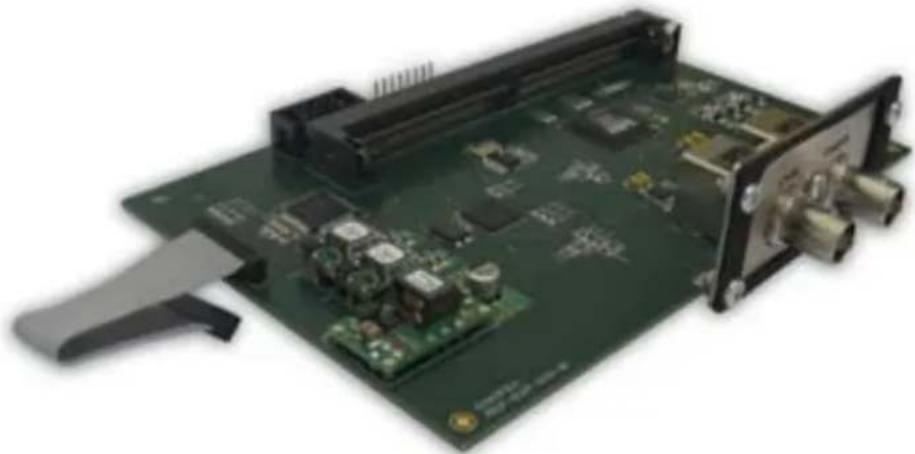
natural_image
Green printed circuit board with various electronic components and connectors (no visible text or symbols)Fig 3-1: RM-HD1 Expansion Card
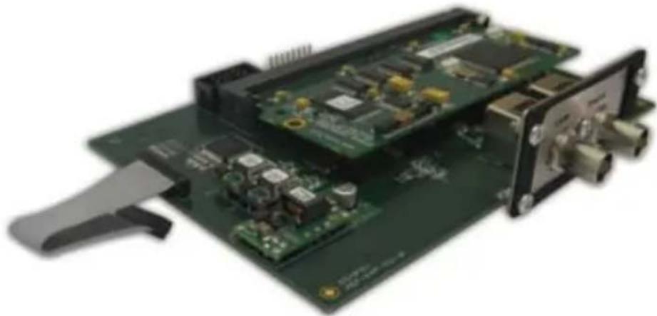
natural_image
Close-up of a green printed circuit board with visible components and connectors (no text or symbols)Fig 3-2: RM-HDE1 Expansion Card
System Block Diagram
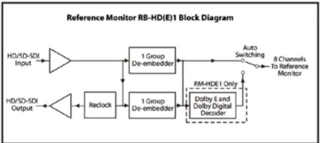
flowchart
graph LR
    A["HD/SD-SDI Input"] --> B["Amplifier"]
    C["HD/SD-SDI Output"] --> D["Amplifier"]
    B --> E["1 Group De-embedder"]
    D --> F["Reclock"]
    E --> G["1 Group De-embedder"]
    F --> H["1 Group De-embedder"]
    G --> I["Dolby E and Dolby Digital Decoder"]
    H --> I
    I --> J["Auto Switching"]
    J --> K["8 Channels To Reference Monitor"]
    style I stroke-dasharray: 5 5
Fig 3-3: RM-HD(E)1 Block Diagram
Fitting The Expansion Card
To install an RM-HD1 or RM-HDE1 expansion card into a Reference Monitor, follow the procedure below.
1) Disconnect the Reference Monitor from the mains supply.
2) Remove all the lid screws and take off the lid.
3) Remove the rear blanking plate (4 x M3 x 6 screws).
4) Remove the nylock nut from the main PCB (second one in from the left of the unit when looking from the rear) and fit the 27mm M3 pillar on to the stud.
5) Remove the self tapping screw from the plastic mount on the expansion board and remove the plate.
6) Place the expansion board plate into the rear of the unit (do not fix it yet as it will need to be loose to aid in the alignment of the expansion board).
7) Plug the expansion board trailing cable into the expansion connector on the main board.
8) Insert the expansion board into the rear of the unit, putting the BNC connectors through the loose plate first.
9) Once in position, screw the expansion plate to the rear of the unit with the 4 x M3 x 6mm screws removed earlier.
10) Fix the expansion board to the plate with the self tap screw into the plastic mount on the board.
11) Screw the expansion board to the pillar with the M3 x 6 screw supplied.
12) Refit the lid with the 19 off M3 x 8mm countersunk screws. Ensure that all screws are fitted loosely before finally tightening.
13) Reconnect your Reference Monitor to the mains supply and check operation.

natural_image
Abstract graphic with two white swords and a central emblem, set against a blue gradient background (no text or symbols)
natural_image
Abstract graphic with two stylized swords and a circular emblem, set against a blue background (no text or symbols)Technical Specification RM-HD1 & RM-HDE1
SDI Input
SDI Video: SMPTE 259M - SD @ 270 Mbps or
SMPTE 292M - HD @ 1.5 Gbps
Input Impedance: 75Ω
SDI Output
SDI Video: Reclocked input
Output Impedance: 75Ω
Output Level: 0.8 Vp-p
Return Loss: > 15 dB (1.5 GHz)
Jitter: < 0.2UI
Embedded Audio
Standard: SMPTE 272M or SMPTE 299M 24 bit 48 kHz synchronous/asynchronous*
*Audio must be synchronous in SD. If asynchronous audio is presented in an HD input then only one group can be presented at any one time.
Connectors
HD-SDI Input: 1 x BNC 75Ω SDI input
HD-SDI Output: 1 x BNC 75Ω SDI output (reclocked loop through)
Equipment Type
RM-HD1: HD-SDI expansion card
RM-HDE1: HD-SDI & Dolby E Decoder expansion card
Physical Specification
Dimensions (Raw): 15cm (W) x 11.5cm (D) x 3.1cm (H)
5.9" (W) × 4.5" (D*) × 1.2" (H) (1U)
Dimensions (Boxed): 25cm (W) x 20cm (D) x 10cm (H)
9.8" (W) × 7.9" (D*) × 3.9" (H) (1U)
Weight (RM-HD1): Nett: 0.13kg Gross: 0.4kg
Nett: 0.3lb Gross: 0.9lb
Weight (RM-HDE1): Nett: 0.15kg Gross: 0.4kg
Nett: 0.3lb Gross: 0.9lb
Serial Interface Commands & Responses Protocol
Sonifex SCi remote control software handles all communication with the Reference Monitors via a convenient graphical user interface. However, this protocol is provided for those users who wish to develop their own remote control applications or communicate with the Reference Monitors using a text-based terminal program.
For more information on how to install and operate the SCi software, please see page 54.
Serial Data Format
Connection is 19200,e,8,1 with XON/XOFF flow control.
Commands are case-insensitive and all parameters are in hex.
Commands should be terminated in a carriage return character, a line feed character may be sent but it will be ignored.
Further commands sent before the first command is acknowledged will be ignored. Responses will be CR & LF terminated.
After power up a welcome string is sent – "Initialising Sonifex Reference Monitor...done"
Remote Control Commands
Command Description Response
BSL:nn - Select input Bank ACK:
nn = 01 selects first Bank.
nn = 02 selects second Bank, etc.
DWN:* - Download firmware update. ACK: Then send .DWN file as supplied. ACK:
Faa:xxxxxxxxxxxxxyyyyyyyyyyyyyzzzzzzzzzzzz ACK:
- Set user-variable equalisation coefficients
aa = EQ band number (01-05)
xxxxxxxxxxxx = five-byte coefficient 1 data.
yyyyyyyyyyyy = five-byte coefficient 2 data.
zzzzzzzzzzzz = five-byte coefficient 3 data.
FPL:x - Front panel lock ACK:
Where: x = 0 unlocks the front panel. x = 1 locks the front panel (hex values 1 to F accepted and have same effect as 1).
The front panel lock setting is not stored when power is lost.
Gaa: - Get user-variable equalisation coefficients
Gaa: + data as for Faa
Where: aa = EQ band number (01-05)
xxxxxxxxxxxx = five-byte coefficient 1 data.
yyyyyyyyyyyy = five-byte coefficient 2 data.
zzzzzzzzzzzz = five-byte coefficient 3 data.
4
SERIAL INTERFACE COMMANDS & RESPONSES


natural_image
Abstract graphic of two stylized swords with a circular emblem, set against a blue background (no text or symbols)Command Description Response
LCK: - AES/EBU PLL Lock status Request
Response depends on model type:
RM-2S4 responds: LCK:x
Where: x = lock status of selected stereo source. No further lock information is available.
RM-2S10 responds: LCK:x+yyyyMMddyyyy
Where: x = lock status of selected stereo source.
y = lock status of all ten AES inputs.
RM-4C8 responds: LCK:xy+zzzz
Where: x = lock status of left selected mono source.
y = lock status of right selected mono source.
z = lock status of four mono sources in currently selected bank.
No lock data is available for an unselected bank.
LCK:ab - Set GPIO lock output logic preferences ACK:
a = 0 selects normal polarity (lock = low/conducting output).
a = 1 selects inverted polarity (lock = high/non-conducting output).
b = 0 selects the logical OR of the LH & RH channel lock status.
b = 1 selects the logical AND of the LH & RH channel lock status.
MOD:x,y - Remote control of audio Modifiers ACK:
Where: x = modifier number, 0 to A (hex - values B to F accepted but have no effect).
y = 0 to turn modifier off.
y = 1 to turn modifier on (hex values 1 to F accepted and have same effect as 1).
The modifier numbers are:
0 = DIM, 1 = CUT L, 2 = CUT R, 5 = MONO, 6 = PHASE INVERT and 7 = M + S
OPT:x,yy - Set technical options
ACK:
x = option number (1...F in hex)
yy = new value for option parameter (00...FF in hex)
All OPT settings are stored in non-volatile memory and retained during power loss.
OPT:1,xx
-Turn off presence detection:
ACK:
Where: x = 00 enables the presence detectors (default setting).
x = 01 disables the presence detectors (hex values 01 to FF
accepted and have same effect as 01).
Command Description Response
OPT:2,xx Source autodetection for RM-2S10 (see page 6): ACK:
Where: x = 00 selects normal operation (default setting)
x = 01 enables source autoselection (hex values 01 to FF accepted and have same effect as 01).
The SRQ: query will correctly report the bank currently in use.
The UID: query will report a single bank of 10 sources rather than two when autoselect is enabled.
SER: - Serial Number request SER:nnnnnn
SRQ: - Status request SRQ:BxLyRz
Where: x = current bank number (1...n).
y = current source number for LH speaker (1...n).
z = current source number for RH speaker (1...n).
SS1:nn - Set Left-hand Source ACK:
nn = Source number, starting with 01.
SS2:nn - Set Right-hand Source ACK:
nn = Source number, starting with 01.
UID:* - Unit ID Request UID:RM4:V11yyyy
or UID:RM-2S4-xxxxxx
or UID:RM-2S10-xxxxxx
or UID:RM-4C8-xxxxxx
or UID:RM4/A (bootloader)
Where: x = number of sources available in each of banks 1-6
y = dependent on Banks fitted.
VER:* - Firmware Version Request VER:n.nn
or BOOT:n.nn (bootloader)
* = these commands also valid in Bootloader mode.
Error Messages
ERR:01 - returned if Command Not Found.
ERR:02 - returned if Missing Parameter.
ERR:04 - returned if Parameter out of range.
ERR:08 - returned if Checksum Error occurs during reprogramming.
Firmware Updates
The internal firmware of the Reference Monitors can be updated to take advantage of newly added features. It is recommended that this be done using the Sonifex SCi remote control package, but it may also be done using the command protocol provided and the "Send Text File" (or similar) facility in text-based terminal programs such as Hyperterminal. When prompted for a filename, locate and select the .DWN file provided with the firmware update.
4
SERIAL INTERFACE COMMANDS & RESPONSES
[Non-Text]

natural_image
Abstract graphic with two white swords and a circular emblem on blue background (no text or symbols)If using a terminal program, to achieve reliable data transfer the Line Delay (found under File>Properties>Settings>ASCII Setup in Hyperteminal) should be set to 20ms.
It is vital that neither the serial connection nor mains power to the Reference Monitor should be interrupted during the update process. If this should happen, or the update is unsuccessful for any other reason, the Reference Monitor will not operate normally and will instead enter a protected Bootloader mode. In this mode, the unit has a limited command set and will await a successful retry of the update process.
Should the firmware update appear to succeed but the unit not behave as expected, the update may be repeated either via the DWN: command (if the unit will respond to commands) or, in extreme circumstances, by setting switch number 12 in Block 1 of configuration switches (found on the underside of the unit) to ON. This action will force the Bootloader to run and allow initiation of an update under any circumstances. After completion of the update, the switch should be returned to the OFF position.
User-Variable EQ Parameter Format
The DSP coefficients for the user-variable EQ need to be pre-calculated before being sent to the Reference Monitor.
Each band of EQ is a parametric equaliser with the following parameters:
F = centre frequency in Hz,
BW = bandwidth in octaves
G = height of peak/trough at centre frequency (linear, so 6dB=2.0, 12dB=4.0, etc)
First, the following intermediate values should be calculated:
R = ((2^) - 1) / (2^(BW / 2))
K = tan(pi*F/48000)
A = G - 1
From these, the three coefficients M1, M2 and M3 can be calculated. They differ according to whether boost or cut is required.
If boost is required:
M1 = (A*R*K)/(1+(R*K)+(K^2))
M2 = (4*(K^2))/(1+(R*K)+(K^2))
M3 = (1-(R*K)+(K^2))/(1+(R*K)+(K^2))
If cut is required:
M1 = -(A*R*K)/(1+(G*R*K)+(K^2))
M2 = (4*(K^2))/(1+(G*R*K)+(K^2))
M3 = (1-(G*R*K)+(K^2))/(1+(G*R*K)+(K^2))
The resulting three coefficients should then be converted to S3.24 format, i.e. one sign bit, three integer bits and 24 fractional bits. It is in this format that they are sent to the Reference Monitor. A five-byte string (five hex character pairs) is sent with the coefficient bytes sent MSB first. The upper nibble of the MSB should be all zeros.
Coefficient updates will be applied instantly.

natural_image
Abstract graphic with two stylized swords and a circular emblem, set against a blue background (no text or symbols)5
SCI REMOTE CONTROL SOFTWARE


natural_image
Abstract graphic with two tall white swords and a central circular emblem, set against a blue gradient background (no text or symbols)Reference Monitor SCi Remote Control Software
Sonifex SCi software is free of charge software available to control the Reference Monitor range of audio monitors, as well as other Sonifex products, using either RS232 or USB connections.
Download the Latest SCi Software
This is located on the Sonifex website in the Software Downloads section: http://www.sonifex.co.uk/technical/software/index.shtml
Download and install the software.
Connecting Using USB Port
Before the Reference Monitor can be used with the SCi software, you need to install the latest version of the USB drivers. These can be found on the Sonifex website located in the 'Sonifex Reference Monitor' section of Software Downloads: http://www.sonifex.co.uk/technical/software/index.shtml
Once you have downloaded the drivers, unzip them to a suitable folder. Connect the Reference Monitor to your computer using a USB cable and power up the Reference Monitor.
The 'Found New Hardware' wizard will pop up and you are ready to begin installation. If Windows asks to connect to the internet to find the drivers, select the option 'Not this Time', click 'Next', and select the option 'I Will Choose The Driver To Install'. Point the wizard to the directory into which you unzipped the USB driver files and continue with the installation.
Connecting using the RS232 Serial Port
You do not need to download drivers when connecting via this method. Simply connect your Reference Monitor to your computer using a serial cable and you are ready for operation.
Using SCi For The First Time
Once you are connected, double click the SCi icon. You will be presented with the SCi Launcher:
Click on the large 'Plus' button and the software will try and communicate with the relevant serial ports to 'discover' your connected devices.

Fig 5-1: SCi Launcher
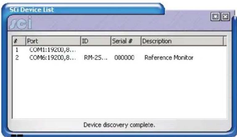
Fig 5-2: SCi Device Discovery Panel
Your attached Reference Monitor(s) will be shown in the list. If they are not listed, check the cable(s) between the Reference Monitor and your PC.
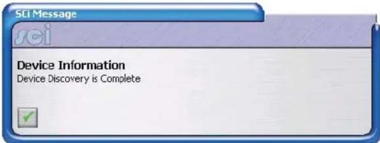
Fig 5-3: SCi Device Information Panel
Close the device dialog by clicking on the cross in the top right corner. The Reference Monitor now appears in the SCi Launcher.
Loaded Launcher
Double-click on this to gain access to the Reference Monitor controls.
![Launcher sci Reference Monitor RM-254-400000 [000000]](/content/2026/05/974190/images/905dc0a2b55a4b7e885f6aad6c1d45a59d288bfd7d3d57b3f54fa96944c44fed.jpg)
Fig 5-4: SCi Launcher Loaded

natural_image
Abstract graphic with two white swords and a circular emblem on blue background (no text or symbols)5
SCI REMOTE CONTROL SOFTWARE


natural_image
Abstract graphic with two white swords and a circular emblem on blue background (no text or symbols)SCi For Reference Monitors
The graphical interface allows you to control the Reference Monitor remotely. Bank/Source Selection, EQ parameter adjustment and front panel Modifier controls can all be accessed and adjusted from this main panel.
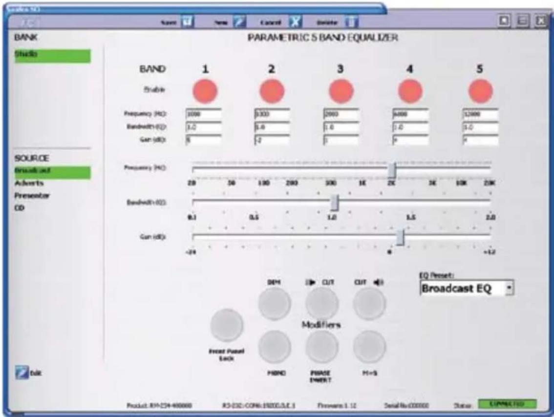
Fig 5-5: SCi Main Screen
Bank & Source Selection & Editing
On the left hand side of this panel you have the ability to select Banks and their respected Sources and to edit their names. Depending upon the model of your Reference Monitor, or if expansion cards are fitted, the number of available Banks varies. Each Bank shows its respected Sources and you can edit the names of the Sources for each Bank.
To edit a Source or Bank name, click on the Edit icon located on the bottom left of the screen and then click on the Source or Bank that you wish to edit. Type the Source or Bank name into the text box and press 'Enter' on the keyboard. Press the Cancel button before hitting the 'Enter' key to cancel the process.
5 Band Parametric Equalizer
The 5 band parametric EQ built into the Reference Monitors is only available using serial control, so using SCi is an easy way to configure the EQ.
The 5 bands are shown on the screen and an 'EQ Preset' box allows you to select default presets. The default presets cannot be edited. However you can generate preset settings yourself, called Custom EQ Settings, which you can save off.
To create a new EQ preset, click the 'New' Icon on the top toolbar. You will now be in EQ edit mode. Click the Enable button for the EQ band that you wish to adjust, e.g. Band 1. This will activate the EQ for that selected band.
By clicking in the Frequency, Bandwidth and Gain edit boxes for Band 1, the 3 EQ faders respectively are enabled for that band and can be adjusted to your taste. The values are updated as you drag the faders, but are only sent to the Reference Monitor once you have released the mouse click. Please note that the sound output of the Reference Monitor takes a few seconds to stabilise once a new set of EQ parameters has been loaded.
You can navigate through the rest of the Band edit boxes by either clicking in them with your mouse, or by using Tab on your keyboard. The values in the edit boxes can also be adjusted manually by typing in values. A bevel appears around the band that you are editing.
Once you are happy with the EQ preset that you are defining, click the Save Button on the top toolbar. A text edit box appears for you to type in the name of your new preset. Press the 'Enter' key to Save the preset name. The name now appears in the 'EQ Preset' box, available for selection. You can also edit and save over existing Custom EQ Settings.
When SCi first connects to a Reference Monitor, it reads its current EQ settings. If these EQ parameters match up with a known EQ Preset, then that preset is loaded in. If not, then the EQ settings are shown as a 'Recalled Preset'. This can be saved as a New Preset if you wish.
To Delete an EQ Preset, select the Preset and then press the Delete button at the top of the screen.
Front Panel Modifiers
These are a replication of the front panel Reference Monitor functions which offer 'Dim, Mono, Left Cut, Right Cut, Phase Invert, and M+S (Middle + Side)' selection. The status of these are automatically recalled from the Reference Monitor and changes on the Reference Monitor are reflected in SCi and vice-versa.
A Front Panel Lock button is also included and when active disables the functionality of the Reference Monitor front panel. However you will still have full control from within SCi.

natural_image
Abstract graphic with two stylized swords and a circular emblem, set against a blue background (no text or symbols)SONIFEX
www.sonifex.co.uk
t:+44 (0)1933 650 700
f:+44 (0)1933 650 726
sales@sonifex.co.uk

natural_image
Close-up of electronic equipment modules with no visible text or symbols on main surfaces- Reference Monitors User Handbook
- Warranty i
- Safety Information iv
- Installation Information v
- Reference Monitors Introduction 1
- Figures
- Warranty
- Warranty and Liability
- Unpacking the Reference Monitor
- Item Quantity Reference Monitor
- Returning the Warranty Card
- Safety Information
- Safety of Mains Operated Equipment
- Voltage Setting Checks
- Fuse Rating
- Power Cable and Connection
- Wire Colour Connection
- Ordering the Correct Mains Lead
- Installation Information
- Atmosphere
- Electromagnetic Radiation
- WEEE & RoHS Directives - Sonifex Statement
- Reference Monitors Introduction
- Detail In The Design
- Anti-Vibration
- Accurate Sound System
- DSP Based Design
- Audio Modifiers
- Band Parametric Equalisation
- Front Panel Lock-Out
- Optional HD Expansion Cards
- 1
- REFERENCE MONITORS RM-2S4 & RM-2S10
- Power LED
- Auto-Selection of Inputs
- Bank Selector
- Source Presence Indicators (RM-2S10 only)
- Main Meters
- Meter Labelling
- Brightness Control
- PHASE Meter
- BALANCE Control
- LEVEL Control
- Headphone Output
- STATUS LED Indicators
- LIMIT indicator
- CLIP indicator
- LOCK indicator
- OPT indicator
- DIM Audio Modifier
- CUT L & CUT R Audio Modifiers
- MONO Audio Modifier
- PHASE INVERT Audio Modifier
- MIDDLE + SIDE (M+S) Audio Modifier
- Rear Panel Connections & Operation
- Mains Power
- Digital Input Termination
- Input Gain Adjustment
- Audio Inputs (RM-2S4)
- Audio Inputs (RM-2S10)
- Line Level Audio Outputs
- Expansion Port
- Remote Inputs and Outputs
- RS232 Remote Control
- USB Remote Control
- Technical Specification RM-2S4 & RM-2S10
- Inputs
- Line Level Outputs
- User-Variable Equalisation
- Amplifier/Loudspeakers
- Level Metering
- Phase Metering
- Remote Control
- Status Indicators
- Connectors
- DIP Switch Settings (Underneath The Unit, See Fig 1-17)
- Block 1 (RM-2S4 & RM-2S10)
- Block 2 (RM-2S4)
- Block 2 (RM-2S10)
- Equipment Type
- Physical Specification
- 2
- REFERENCE MONITORS RM-4C8
- RM-4C8 Reference Monitor, 4 LED meters, 8 channel inputs & dual selectors
- Introduction
- LOCK L and LOCK R indicators
- Audio Inputs
- Technical Specification RM-4C8
- DIP Switch Settings (Underneath The Unit, See Fig 2-6)
- Block 1
- Block 2
- 3
- REFERENCE MONITORS RM-HD(E)1
- RM-HD1 Reference Monitor HD-SDI Expansion Card & RM-HDE1 Reference Monitor HD-SDI & Dolby E Expansion Card
- System Block Diagram
- Fitting The Expansion Card
- Technical Specification RM-HD1 & RM-HDE1
- SDI Input
- SDI Output
- Serial Interface Commands & Responses Protocol
- Serial Data Format
- Remote Control Commands
- Command Description Response
- 4
- SERIAL INTERFACE COMMANDS & RESPONSES
- Error Messages
- Firmware Updates
- User-Variable EQ Parameter Format
- 5
- SCI REMOTE CONTROL SOFTWARE
- Reference Monitor SCi Remote Control Software
- Download the Latest SCi Software
- Connecting Using USB Port
- Connecting using the RS232 Serial Port
- Using SCi For The First Time
- Port ID Serial # Description
- Loaded Launcher
- SCi For Reference Monitors
- Bank & Source Selection & Editing
- Band Parametric Equalizer
- Front Panel Modifiers
- SONIFEX
Brand : Sonifex
Model : RM-2S10
Category : Monitor