
Redbox RB-MA1 - Professional audio equipment Sonifex - Free user manual and instructions
Find the device manual for free Redbox RB-MA1 Sonifex in PDF.


| Product Type | Single Microphone Amplifier |
| Model | Redbox RB-MA1 by Sonifex |
| Channels | 1 |
| Input Connector | 1 x XLR-3 female (electronically balanced) |
| Output Connector | 1 x XLR-3 male (balanced, can be unbalanced) |
| Gain Range | 36 dB to 75 dB (adjustable via recessed potentiometer) |
| Phantom Power | +48 V (switchable per channel, 14 mA via 6k8 resistors) |
| Low Frequency Filter | 125 Hz high-pass @ 6 dB/octave (switchable) |
| Frequency Response | 20 Hz – 20 kHz ±0.1 dB (600 Ω load ref 1 kHz) |
| Maximum Output Level | +28 dBu |
| Output Impedance | < 50 Ω |
| Input Impedance | 20 kΩ nominal balanced |
| E.I.N. (Equivalent Input Noise) | 130 dB |
| Distortion (THD) | 0.01% @ 1 kHz, ref +8 dBu output |
| Common Mode Rejection | > 66 dB typically |
| Power Supply | Filtered IEC, 110–120 V or 220–240 V switchable, fused, 6 W max |
| Dimensions (Raw) | 28 cm (W) x 10.8 cm (D) x 4.2 cm (H) (1U) |
| Dimensions (Boxed) | 36 cm (W) x 20.5 cm (D) x 6 cm (H) |
| Weight (Net) | 0.90 kg |
| Weight (Gross) | 1.35 kg |
| Rack Mounting | 1U, optional RB-RK1 front rack kit or RB-RK2 rear kit |
| Safety | CE marked, conforms to safety regulations; no user-serviceable parts inside |
| Warranty | 12 months against defects (conditions apply) |
| WEEE & RoHS | Compliant; lead-free manufacturing |
Frequently Asked Questions - Redbox RB-MA1 Sonifex
User questions about Redbox RB-MA1 Sonifex
0 question about this device. Answer the ones you know or ask your own.
Ask a new question about this device
Download the instructions for your Professional audio equipment in PDF format for free! Find your manual Redbox RB-MA1 - Sonifex and take your electronic device back in hand. On this page are published all the documents necessary for the use of your device. Redbox RB-MA1 by Sonifex.
USER MANUAL Redbox RB-MA1 Sonifex

Redbox User Handbook No3
Mixers & Source Selectors, Microphone Amplifiers, Stereo to Mono Converters, General Interfaces
RB-SS10 10 way stereo analogue source selector/mixer
RB-DSS10 10 way stereo digital source selector
RB-PMX4 10 input, 4 output analogue preset mixer (1U)
RB-SSML1 Mic/line source selector with compressor/limiter
RB-MA1 Microphone amplifier, single
RB-MA2 Microphone amplifier, dual
RB-DMA2 Dual digital microphone amplifier
RB-ML2 Microphone limiter, 2 channel
RB-SL2 Twin mono, or stereo limiter
RB-SM1 Stereo to mono converter, single
RB-SM2 Stereo to mono converter, dual
RB-LC3 3 way light/power controller
RB-MM1 Mix minus generator

Revision 1.00 October, 2006
©Sonifex Ltd, 2000-6
All Rights Reserved
Sonifex Ltd, 61, Station Road, Irthlingborough,
Northants, NN9 5QE, England.
Tel: +44 (0)1933 650 700
Fax: +44 (0)1933 650 726
Email : sales@sonifex.co.uk or technical.support@sonifex.co.uk
Web : http://www.sonifex.co.uk
Information in this document is subject to change without notice and does not represent a commitment on the part of Sonifex Ltd. Sonifex Ltd shall not be liable for any loss or damage whatsoever arising from the use of information or any error contained in this manual.
No part of this manual may be reproduced or transmitted in any form or by any means, electronic or mechanical, including photocopying, recording, or information storage and retrieval systems, for any purpose other than the purchaser's personal use, without the express written permission of Sonifex Ltd.
Unless otherwise noted, all names of companies, products and persons contained herein are part of a completely fictitious adaptation and are designed solely to document the use of Sonifex products.
Warranty i
Warranty and Liability - important the purchaser is advised to read this clause i Unpacking the Redbox ii Returning the Warranty Card iii
Safety Information iii
Safety of Mains Operated Equipment iii
Voltage Setting Checks iii
Fuse Rating iii
Power Cable and Connection iv
Ordering the Correct Mains Lead iv
Installation Information iv
Atmosphere iv
Electromagnetic Radiation iv
Fitting Redboxes iv
WEEE & RoHS Directives - Sonifex Statement vi
1 RB-SS10 10 Way Stereo Analogue Source Selector/Mixer 1
Introduction 1 System Block Diagram 2 Front Panel Indicators & Controls 2 Illuminated Push Buttons 2 Front Panel Gain Controls 3 Headphone Output 3 Volume Control 3 Additional Modes 3 Configuring the Additional Modes 3 Rear Panel Connections and Operation 4 Inputs 4 Outputs 4 Altering the Master Output Level 4 RB-SS10 Additional Audio Input Connectors 5 RB-SS10 Remote Start I/O 6 Remote Select/Switch Inputs 7 Status Outputs 8 Technical Specifications RB-SS10 9
2 RB-DSS10 10 Way Stereo Digital Source Selector 11
Introduction 11 System Block Diagram 12 Front Panel Indicators & Controls 12 Power Indicator 13 Illuminated Push Buttons 13 Headphone Output 13 Volume Control 13 Additional Modes 13 Configuring the Additional Modes 13 Rear Panel Connections and Operation 14 RB-DSS10 Inputs 14 AES/EBU Inputs 14 RB-DSS10 Outputs 14 AES/EBU Outputs 14 Digital Audio Inputs & S/PDIF Output 15 Remote Start I/O 15 Remote Select/Switch Inputs 17 Status Outputs 18 Technical Specifications RB-DSS10 19

natural_image
Red industrial machine with control panel and buttons (no visible text or symbols)
3 RB-PMX4 10 Input, 4 Output Analogue Preset Mixer 21
Introduction 21
System Block Diagram 22
Rear Panel Connections and Operation 22
Outputs 1-4 23
Front Panel Controls 23
Switch Banks 23
Input Gain Controls 23
Technical Specifications RB-PMX4 24
4 RB-SSML1 Mic/Line Source Selector with Compressor Limiter 25
Introduction 25
System Block Diagram 26
Rear Panel Connections 26
Stereo Monitor Input 27
Stereo Monitor Pad & Volume Control 27
Mic Input 27
Mic Input Gain 27
Using Phantom Powered Microphones 27
Using the LF Filter 28
Compression Active on Mic Input Only 28
Peak Hold Disabled on LED Meter 28
Stereo Line Input 28
Stereo Input Gain Pad 28
Stereo Line Output 28
Front Panel Controls 28
Mic & Line Volume Controls 28
Mic/Line Select Switch 29
Bypass Button 29
Applying Compression 29
LED Metering 29
Headphone Outputs 29
Technical Specifications RB-SSML1 30
5 RB-MA1 Single & RB-MA2 Dual Microphone Amplifiers 31
Introduction 31
System Block Diagram 31
Rear Panel Connections and Operation 32
Mic Inputs 32
Input Gain 32
Using Phantom Powered Microphones 33
Using the LF Filter 33
Output 33
Technical Specifications RB-MA1 & RB-MA2 34
6 RB-DMA2 Dual Digital Microphone Amplifier 35
Introduction 35
System Block Diagram 36
Front Panel Indicators & Controls 36
Sync & Power Indicator 37
Input Level Adjustment 37
Disabling the Fine Gain Control Knob 37
Input Level Indicators 37
Rear Panel Connections and Operation 37
RB-DMA2 Inputs 38
Mic Inputs 38
Word Clock Sync Input 38
S/PDIF Sync Input 38
RB-DMA2 Outputs 38
AES/EBU Output 38
S/PDIF Output 38
Analogue Line Outputs 38
Rear Panel Controls 39
Status Select Switches 39
Output Routing 39
Phantom Power & LF Filter 39
Digital Sync & Output Select Buttons 40
Frequency and Sync Mode Rotary Switch 40
Test/Calibration Mode 41
Technical Specifications RB-DMA2 42
7 RB-ML2 Stereo Microphone & Line Level Limiter 44
Introduction 44
System Block Diagram 45
Rear Panel Connections and Operation 45
Mic / Line Inputs 46
Mic Input Gain 46
Using Phantom Powered Microphones 46
Using the LF Filter 46
Mic / Line Outputs 46
Mic / Line Output Gain 47
Level Limiting 47
Mode Select Switch 47
Technical Specifications RB-ML2 48
8 RB-SL2 Twin Mono, or Stereo, Limiter 50
Introduction 50
System Block Diagram 50
Rear Panel Connections and Operation 51
Outputs 51
Inputs 51
Gain Control 51
Mode Switch 51
Technical Specifications RB-SL2 52
9 RB-SM1 Single & RB-SM2 Dual Stereo To Mono Converter 53
Introduction 53
System Block Diagram 53
Rear Panel Connections and Operation 54
Stereo Inputs 1 (& 2) 55
Mono Output 1 (& 2) 55
Output Gain 55
Technical Specifications RB-SM1 & RB-SM2 56
10 RB-LC3 3 Way Light/Power Controller 57
Introduction 57
System Block Diagram 58
Rear Panel Connections and Operation 58
Switched Mains Outputs 59
Telephone Connections 59
Remote External Control Inputs 59
Configuration Switches 60
Flash Rate Preset Potentiometer 62
Technical Specifications RB-LC3 63

natural_image
Close-up of a red electronic device with buttons and display screens (no visible text or symbols)
11 RB-MM1 Mix Minus Generator 64
Introduction 64
System Block Diagram 64
Front Panel Indicator 65
Rear Panel Connections and Operation 65
Stereo Inputs From Mixer Main Output 65
Input From Mixer Telephone Fader 65
Output Null Adjustments (LF and Full-Band) 65
Band Pass Filter Switch 66
Output to Telephone Balance Unit (TBU) 66
Output Level Adjustment 66
Operation of the RB-MM1 66
Technical Specification RB-MM1 67
Figures
Fig A: Packing List. ii
Fig B: Fuse Rating Table. iii
Fig C: Mains Cable Wire Colours iv
Fig D: Mains Lead Table. iv
Fig E: RB-RK1Small Redbox Front Rack-mount Kit. v
Fig F: RB-RK2 Small Redbox Rear Rack-mount Kit. v
Fig G: RB-RK3 Large Redbox Rear Rack-mount Kit. v
Fig 1-1: RB-SS10 Front Panel. 1
Fig 1-2: RB-SS10 System Block Diagram. 2
Fig 1-3: RB-SS10 Front Panel. 2
Fig 1-4: RB-SS10 Rear Panel. 4
Fig 1-5: Analogue Audio Inputs Pin Connections 5
Fig 1-6: Remote Start Pin Connections. 6
Fig 1-7: Connection Example. 7
Fig 1-8: Remote Select/Switch Input Connections. 7
Fig 1-9: Connection Example. 8
Fig 1-10: Status Output Pin Connections. 8
Fig 1-11: Connection Example. 9
Fig 2-1: RB-DSS10 Front Panel. 11
Fig 2-2: RB-DSS10 System Block Diagram. 12
Fig 2-3: RB-DSS10 Front Panel. 12
Fig 2-4: RB-DSS10 Rear Panel. 14
Fig 2-5: Digital Audio Inputs and S/PDIF Output Pin Connections. 15
Fig 2-6: Remote Start Pin Connections. 16
Fig 2-7: Connection Example. 17
Fig 2-8: Remote Select/Switch Input Connections. 17
Fig 2-9: Connection Example. 17
Fig 2-10: Status Output Pin Connections. 18
Fig 2-11: Connection Example. 18
Fig 3-1: RB-PMX4 Front Panel. 21
Fig 3-2: RB-PMX4 Block Diagram. 22
Fig 3-3: RB-PMX4 Rear Panel. 22
Fig 3-4: RB-PMX4 Front Panel Controls. 23
Fig 4-1: RB-SSML1 Front Panel. 25
Fig 4-2: RB-SSML1 Block Diagram. 26
Fig 4-3: RB-SSML1 Rear Panel. 26
Fig 4-4: DIP Switch to Control Mic & Meter Features. 27
Fig 4-5: RB-SSML1 Front Panel. 28
Fig 5-1: RB-MA1 & RB-MA2 Front Panel. 31
Fig 5-2: RB-MA1 & RB-MA2 Block Diagram Single Channel. 31
Fig 5-3: RB-MA1 Rear Panel. 32

natural_image
Red industrial machine with control panel and buttons (no visible text or symbols)
Fig 5-4: RB-MA2 Rear Panel. 32
Fig 5-5: Switch to Control LF Filter and Phantom Power. 33
Fig 6-1: RB-DMA2 Front Panel. 35
Fig 6-2: RB-DMA2 System Block Diagram. 36
Fig 6-3: RB-DMA2 Front Panel. 36
Fig 6-4: Jumpers to Disable Fine Gain Control. 37
Fig 6-5: RB-DMA2 Rear Panel. 37
Fig 6-6: RB-DMA2 Status Select Switches. 39
Fig 6-7: RB-DMA2 Frequency and Sync Rotary Switch Selections. 41
Fig 7-1: RB-ML2 Front Panel. 44
Fig 7-2: RB-ML2 Block Diagram. 45
Fig 7-3: RB-ML2 Rear Panel. 45
Fig 7-4: Switch to Control LF Filter and Phantom Power. 46
Fig 8-1: RB-SL2 Front Panel. 50
Fig 8-2: RB-SL2 Block Diagram. 50
Fig 8-3: RB-SL2 Rear Panel. 51
Fig 9-1: RB-SM1 & RB-SM2 Front Panel. 53
Fig 9-2: RB-SM1 & RB-SM2 Block Diagram Single Channel. 53
Fig 9-3: RB-SM1 Rear Panel.. 54
Fig 9-4: RB-SM2 Rear Panel. 54
Fig 10-1: RB-LC3 Front Panel. 57
Fig 10-2: RB-LC3 Block Diagram. 58
Fig 10-3: RB-LC3 Rear Panel 58
Fig 10-4: Output 1 Configuration Setting. 60
Fig 10-5: Output 2 Configuration Settings. 61
Fig 10-6: Output 3 Configuration Settings. 62
Fig 11-1: RB-MM1 Front Panel. 64
Fig 11-2: RB-MM1 System Block Diagram. 64
Fig 11-3: RB-MM1 Rear Panel. 65
Warranty
Warranty and Liability - important the purchaser is advised to read this clause
(a) The Company agrees to repair or (at its discretion) replace Goods which are found to be defective (fair wear and tear excepted) and which are returned to the Company within 12 months of the date of despatch provided that each of the following are satisfied:
(i) Notification of any defect is given to the Company immediately upon its becoming apparent to the Purchaser;
(ii) The Goods have only been operated under normal operating conditions and have only been subject to normal use (and in particular the Goods must have been correctly connected and must not have been subject to high voltage or to ionising radiation and must not have been used contrary to the Company's technical recommendations);
(iii) The Goods are returned to the Company's premises at the Purchaser's expense;
(iv) Any Goods or parts of Goods replaced shall become the property of the Company;
(v) No work whatsoever (other than normal and proper maintenance) has been carried out to the Goods or any part of the Goods without the Company's prior written consent;
(vi) The defect has not arisen from a design made, furnished or specified by the Purchaser;
(vii) The Goods have been assembled or incorporated into other goods only in accordance with any instructions issued by the Company;
(viii) The defect has not arisen from a design modified by the Purchaser;
(ix) The defect has not arisen from an item manufactured by a person other than the Company. In respect of any item manufactured by a person other than the Company, the Purchaser shall only be entitled to the benefit of any warranty or guarantee provided by such manufacturer to the Company.
(b) In respect of computer software supplied by the Company the Company does not warrant that the use of the software will be uninterrupted or error free.
(c) The Company accepts liability:
(i) For death or personal injury to the extent that it results from the negligence of the Company, its employees (whilst in the course of their employment) or its agents (in the course of the agency);


(ii) For any breach by the Company of any statutory undertaking as to title, quiet possession and freedom from encumbrance.
(d) Subject to conditions (a) and (c) from the time of despatch of the Goods from the Company's premises the Purchaser shall be responsible for any defect in the Goods or loss, damage, nuisance or interference whatsoever consequential economic or otherwise or wastage of material resulting from or caused by or to the Goods. In particular the Company shall not be liable for any loss of profits or other economic losses. The Company accordingly excludes all liability for the same.
(e) At the request and expense of the Purchaser the Company will test the Goods to ascertain performance levels and provide a report of the results of that test. The report will be accurate at the time of the test, to the best of the belief and Knowledge of the Company, and the Company accepts no liability in respect of its accuracy beyond that set out in Condition (a).
(f) Subject to Condition (e) no representation, condition, warranty or other term, express or implied (by statute or otherwise) is given by the Company that the Goods are of any particular quality or standard or will enable the Purchaser to attain any particular performance or result, or will be suitable for any particular purpose or use under specific conditions or will provide any particular capacity, notwithstanding that the requirement for such performance, result or capacity or that such particular purpose or conditions may have been known (or ought to have been known) to the Company, its employees or agents.
(g) (i) To the extent that the Company is held legally liable to the Purchaser for any single breach of contract, tort, representation or other act or default, the Company's liability for the same shall not exceed the Price of the Goods.
(ii) The restriction of liability in Condition (g)(i) shall not apply to any liability accepted by the Seller in Condition (c).
(h) Where the Goods are sold under a consumer transaction (as defined by the Consumer Transactions (Restrictions on Statements) Order 1976) the statutory rights of the Purchaser are not affected by these Conditions of Sale.
Unpacking the Redbox
The Redbox is shipped with the following equipment. Please check your packaging to ensure that you have all of the items below. If anything is missing, please contact the supplier of your equipment immediately.
| Item Quantity | |
| Redbox audio interface 1 | |
| IEC Mains lead fitted with moulded mains plug | 1 |
| Handbook and warranty card | 1 |
Fig A: Packing List.
Each Redbox is shipped in protective packaging and should be inspected for damage before use. Where an item is found to have transit damage, notify the carrier immediately with all the relevant details of the shipment. Packing materials should be kept for inspection and also for if the product needs to be returned.
Returning the Warranty Card
In order to register the date of purchase so that we can keep you informed of any design improvements or modifications, it is important to complete the warranty registration document that is enclosed and return it to Sonifex Ltd in the UK, or register online at www.sonifex.co.uk/register
For your own records you should write down the serial number (which can be found on the rear of the Redbox.
| Serial Number |
Safety Information
Safety of Mains Operated Equipment

This equipment has been designed to meet the safety regulations currently advised in the country of purchase and it conforms to the safety regulations specified by use of the CE Mark.
Warning : There are no user serviceable parts inside the equipment. If you should ever need to look inside the unit, always disconnect the mains supply before removing the equipment covers.
Voltage Setting Checks
Ensure that the machine operating voltage is correct for your mains power supply by checking the box in which your Redbox was supplied. The voltage is shown on the box label. The available voltage settings are 115V, or 230V. Please note that all Redboxes are either switchable between 115V and 230V, or have a universal power supply.
Fuse Rating
The Redboxes are supplied with a single fuse in the live conducting path of the power infeed at the power supply. For reasons of safety it is important that the correct rating and type of fuse is used. Incorrectly rated fuses could present a possible fire hazard, under equipment fault conditions. The fuse ratings for the Redboxes are: -
Voltage Fuse
115 V 200mA, 5 x 20mm SB (except RB-SS10 which is 320 mA)
230 V 100mA, 5 x 20mm SB (except RB-SS10 which is 160 mA)
Fig B: Fuse Rating Table.
The active fuse is fitted on the outside rear panel of the unit.

natural_image
Red industrial machine with control panel and indicator lights (no visible text or symbols)
natural_image
Red and black abstract image with no visible text, numbers, or symbolsPower Cable and Connection
An IEC power connector is supplied with the Redbox, which has a moulded plug, attached – this is a legal requirement. If no moulded plug has been supplied with your Redbox, please contact your supplier, because an IEC connector is always supplied from the Sonifex factory. If for any reason, you need to use the Redbox with a different power cable, you should use the following wiring guidelines:
Wire Colour Connection
Green, or green and yellow Earth (E)
Blue, or Black Neutral (N)
Brown, or Red Live (L)
Fig C: Mains Cable Wire Colours
Ordering the Correct Mains Lead
When ordering a Redbox from Sonifex, it is helpful if you can specify your required operating voltage and mains lead. After the product code add:
UK, for 230V, UK 3 pin to IEC lead

EC, for 230V, European Schuko 2 pin to IEC lead

US, for 115V, 3 pin to IEC lead

AU for 230V, Australasian 3 pin to IEC lead

Fig D: Mains Lead Table.
E.g. order RB-MA1 UK for a UK IEC lead to be supplied.
Installation Information
Atmosphere
The units should be installed in an area that is not subject to excessive temperature variation ( <0^, >50^ ), moisture, dust or vibration.
Electromagnetic Radiation
The cover is connected to earth by means of the fixing screws. It is essential to maintain this earth ground connection to ensure a safe operating environment and provide electromagnetic shielding.
Fitting Redboxes
Redboxes can be fixed to the underside of a mixing desk, or other surfaces using 4.2mm holes in the sides and fixed with 2 x M4 screws or 2 x No. 6 countersink wood screws.
They can also be rack-mounted, with either the front, or rear of the Redbox positioned at the front of the rack:
Front Mounting Redboxes: For rack mounting smaller (28cm) units the optional RB-RK1 (Red) or RB-RK1B (Black) kit can be used (which include 4 off M6 panel fixing screws).

Fig E: RB-RK1Small Redbox Front Rack-mount Kit.
Wherever you see this symbol an RB-RK1 front panel rack kit can be used :
Rear Mounting Redboxes: For rear panel mounting you can use either the RB-RK2, or RB-RK3, depending on the size of your Redbox.
RB-RK2 1U rear panel rack kit for small Redbox range, e.g., RB-BL2

natural_image
Two red metal plates with mounting holes, one showing a curved cutout (no text or symbols)Fig F: RB-RK2 Small Redbox Rear Rack-mount Kit.
e.g. for fitting an RB-BL2:

Wherever you see this symbol an RB-RK2 small Redbox rear panel 19" rack kit can be used :

RB-RK3 1U rear panel rack kit for large Redbox range, e.g., RB-DA6
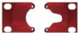
Fig G: RB-RK3 Large Redbox Rear Rack-mount Kit.
e.g. for fitting an RB-DA6:

Wherever you see this symbol an RB-RK3 large Redbox rear panel 19" rack kit can be used :

Note: When fitting the rear-mounting rack-kits, a notch has been left on the inside of the right-hand rack-piece for the mains cable to pass through. Make sure that the mains cable has been put through the notch before attaching the right hand rack-piece.

natural_image
Red industrial machine with control panel and indicator lights (no visible text or symbols)
WEEE & RoHS Directives - Sonifex Statement

The Waste Electrical and Electronic Equipment (WEEE) Directive was agreed on 13 February 2003, along with the related Directive 2002/95/EC on Restrictions of the use of certain Hazardous Substances in electrical and electronic equipment (RoHS).
The Waste Electrical and Electronic Equipment Directive (WEEE) aims to minimise the impacts of electrical and electronic equipment on the environment during their life times and when they become waste. It applies to a huge spectrum of products. It encourages and sets criteria for the collection, treatment, recycling and recovery of waste electrical and electronic equipment. All products manufactured by Sonifex Ltd have the WEEE directive label placed on the case. It gives a contact for individuals who are unsure about the correct procedure when the product has reached its “end of use”.
Sonifex Ltd will be happy to give you information about local organisations that can reprocess the products, or alternatively all products that have reached "end of use" can be returned to Sonifex and will be reprocessed correctly free of charge.
Sonifex Ltd has phased out the use of certain hazardous substances identified in the European Union's Restriction of Hazardous Substances (RoHS) directive. The RoHS directive limits the use of certain hazardous substances currently used in EEE manufacture, including lead, mercury, cadmium, hexavalent chromium, and halide-containing compounds PBB (polybrominated biphenyl) and PBDE (polybrominated diphenyl ether). Elimination of these substances will result in more environmentally friendly recycling of electronic equipment. For the products which Sonifex manufacture, the main area where products were affected was in the use of lead for manufacturing and assembling electronics circuit boards.
Sonifex Ltd practices lead-free (LF) manufacturing processes. LF solder is used on the surface-mount PCB manufacturing processes and for hand soldering. The printed circuit boards (PCBs) used are either gold plated, or immersion tin plated, both of which use no lead. Historically the PCBs were hot air solder levelled (HASL) PCBs which used tin/lead based solder.
The manufacturing processes include the assembly of purchased components from various sources. Product is offered as RoHS compliant, or LF, only after sufficient evidence is received from the component manufacturers that their components are RoHS compliant. Sonifex Ltd relies solely on the distributor, or manufacturer, of the components for identification of RoHS compliance. Thus whilst every effort is made to ensure compliance, Sonifex Ltd makes no warranty, or certification, or declaration of compliance concerning said components.
Sonifex Ltd defines "Lead Free" as pertaining to any product, which has been manufactured by Sonifex Ltd using components which have been declared by the manufacturers as "Lead Free". All statements by Sonifex Ltd of RoHS compliance are based on component manufacturer documentation.
1 RB-SS10 10 Way Stereo Analogue Source Selector/Mixer
Introduction

Fig 1-1: RB-SS10 Front Panel.
The RB-SS10 10 Way Stereo Analogue Source Selector/Mixer is a 1U rack-mount unit that produces a stereo analogue audio output from 10 selectable stereo analogue sources. There are 10 illuminated front panel push buttons, which select and indicate the current channel selection. The selection and indication is also available through a remote connector on the rear panel. To stop accidental front panel selection there is a remote input to inhibit the front panel buttons.
As well as being able to act as a source select module, the RB-SS10 can act as a mixer, by enabling the mix mode (using the remote input).
The gain for left and right inputs can be individually adjusted by using the preset potentiometers on the front panel.
As well as routing the selected audio signal, the unit will also route a remote signal input through the remote connector to the selected input source, for starting external audio equipment such as a CD player.
The front panel headphone output has its own volume control, which is independent of the level adjustment for the main outputs, and has a maximum output level of +12dBu. The volume control can be made to also alter the output level of the main XLR outputs by using a switch on the rear panel to enable/disable this feature.
There is a designation strip on the front panel, useful for giving the buttons a meaningful description. The strip covers the input gain controls so that once configured, they can't easily be altered – ideal for installation work.
The LED on the front panel is used to indicate that power is present on the unit.

natural_image
Close-up of a red electronic device with buttons and a white overlay (no visible text or symbols)1
MIXER & SOURCE SELECTORS
SONIFEX

Front Panel Indicators & Controls

Fig 1-3: RB-SS10 Front Panel.
Illuminated Push Buttons
The front panel contains 10 illuminated push buttons, used for selecting an analogue source. The push button illuminates when the input is selected. The status of pin 12 on the remote connector determines whether the unit is in the selector mode, or the mix mode. When pin 12 is connected to 0V, mix mode is enabled.
In selector mode, one push of a button will select the desired analogue stereo source and pushing the button again will turn it off.
In mix mode, each button you press will select that source allowing multiple sources to be mixed to a single output. Pressing the button again will switch off a source.
There is also a remote input to inhibit the front panel switches. When the front panel inhibit is active, pressing the front panel switches has no effect on the current channel selection.
Front Panel Gain Controls
The input gain can be individually adjusted for left and right channels through pre-set potentiometers which are accessible through the front panel. The gain range of the input is -8dBu to +20dBu.
Headphone Output
The front panel headphone output is a 14 " stereo jack socket and is designed to drive 150mW into 32Ω - 600Ω professional headphones.
Volume Control
The volume control is used to alter the headphone output. It can also be used to alter the main XLR output levels by using a rear panel switch to enable/disable the control.
Additional Modes
An option to set the unit in different modes of operation is available and can be configured at anytime while the unit is powered.
There are currently three modes of operation: Alternate mode, Latched mode and Protected Alternate mode: -
Alternate Mode
In this mode the channels are selected and deselected by a press of the button, as described previously.
Latched Mode
In this mode the selected channel is active only while the button is pressed. As soon as button is released the channel becomes inactive.
Protected Alternate Mode
Operates in a similar manner to the Alternate mode, but a channel cannot be turned off unless switching to another input or while operating in mix-mode and there is more than one channel active. In other words, there will always be a channel routed to the output. NOTE: after setting this mode there will be no channel selected.
Configuring the Additional Modes
While the unit is powered, hold down the input 10 button and press the input 5 button five times. Once completed, the input 10 button will start to flash and the first 3 input buttons will display the current operating mode (as shown below). To change the mode, simply press the input 10 and the buttons will indicate the newly selected mode. Once the required operating mode has been set the unit will restart within five seconds from the last button press.

natural_image
Close-up of a red electronic device with visible components and no readable text or symbols1
MIXER & SOURCE SELECTORS
SONIFEX

| INPUT 1 button on = Alternate mode | |
| INPUT 2 button on = Latched mode | |
| INPUT 3 button on = Protected Alternate mode |
Rear Panel Connections and Operation

Fig 1-4: RB-SS10 Rear Panel.
Inputs
Two of the stereo analogue audio inputs are on XLR-3 pin sockets (female) so that they can be used for equipment which you may want to plug/unplug on a regular basis and isn't pre-wired, e.g. portable recorders.
The four XLR-3 inputs can take balanced professional levels, or unbalanced by using the front panel gain controls, and by connecting the non-phase to the signal ground. They have the following connections:
Pin 1: Screen
Pin 2: Phase
Pin 3: Non-phase
Outputs
The two XLR 3 pin outputs are electronically balanced, and can be wired unbalanced. Each output is individually buffered so that a short circuit on one output will not affect the others. They have the following connections:
Pin 1: Screen
Pin 2: Phase
Pin 3: Non-phase
Altering the Master Output Level
When the Output Level Control push-switch is Enabled (pushed in) on the rear panel, it changes the functionality of the front panel volume control to also alter the level of the master output, as well as the headphone volume.
RB-SS10 Additional Audio Input Connectors
There are 2 off 25 way D-type sockets (female) used for the remaining audio inputs. The INPUTS 3 - 6 (upper) connector contains analogue inputs 3-6, and the INPUTS 7 - 10 (lower) connector contains analogue inputs 7-10.
| Pin No. I/O INPUTS 3 - 6 connector INPUTS 7 – 10 connector | ||
| Pin 1 | Audio input 3 left phase Audio input 7 left phase | ||
| Pin 2 - Chassis ground Chassis ground | ||
| Pin 3 | Audio input 3 right non-phase Audio input 7 right non-phase | ||
| Pin 4 | Audio input 4 left phase Audio input 8 left phase | ||
| Pin 5 - Chassis ground Chassis ground | ||
| Pin 6 | Audio input 4 right non-phase Audio input 8 right non-phase | ||
| Pin 7 | Audio input 5 left phase Audio input 9 left phase | ||
| Pin 8 - Chassis ground Chassis ground | ||
| Pin 9 | Audio input 5 right non-phase Audio input 9 right non-phase | ||
| Pin 10 | Audio input 6 left phase Audio input 10 left phase | ||
| Pin 11 - Chassis ground Chassis ground | ||
| Pin 12 | Audio input 6 right non-phase Audio input 10 right non-phase | ||
| Pin 13 - No internal connection No internal connection | ||
| Pin 14 | Audio input 3 left non-phase Audio input 7 left non-phase | ||
| Pin 15 | Audio input 3 right phase Audio input 7 right phase | ||
| Pin 16 - Chassis ground Chassis ground | ||
| Pin 17 | Audio input 4 left non-phase Audio input 8 left non-phase | ||
| Pin 18 | Audio input 4 right phase Audio input 8 right phase | ||
| Pin 19 - Chassis ground Chassis ground | ||
| Pin 20 | Audio input 5 left non-phase Audio input 9 left non-phase | ||
| Pin 21 | Audio input 5 right phase Audio input 9 right phase | ||
| Pin 22 - Chassis ground Chassis ground | ||
| Pin 23 | Audio input 6 left non-phase Audio input 10 left non-phase | ||
| Pin 24 | Audio input 6 right phase Audio input 10 right phase | ||
| Pin 25 - Chassis ground Chassis ground |
Fig 1-5: Analogue Audio Inputs Pin Connections

natural_image
Red industrial machine with control panel and buttons (no visible text or symbols)1
MIXER & SOURCE SELECTORS
SONIFEX

natural_image
Red and orange abstract background with no visible text, numbers, or symbolsRB-SS10 Remote Start I/O
This 25 way D-type plug (male) connector contains the remote start input connection and the corresponding 10 opto-isolated remote start outputs. This is intended to be used as a method for re-directing a remote start command using a single switch or mixer fader start output, to selected equipment, i.e. CD player, or MD player, etc. This operates in both selector mode and mix mode enabling a single switch to remotely control whichever source is selected or mixed.
| Pin No. I/O | Description |
| Pin 1 O Start | output 1 collector |
| Pin 2 O Start | output 2 collector |
| Pin 3 O Start | output 3 collector |
| Pin 4 O Start | output 4 collector |
| Pin 5 O Start | output 5 collector |
| Pin 6 O Start | output 6 collector |
| Pin 7 O Start | output 7 collector |
| Pin 8 O Start | output 8 collector |
| Pin 9 O Start | output 9 collector |
| Pin 10 O Start | output 10 collector |
| Pin 11 - No internal connection | |
| Pin 12 - No internal connection | |
| Pin 13 I Remote start input signal | |
| Pin 14 O Start output 1 | emitter |
| Pin 15 O Start output 2 | emitter |
| Pin 16 O Start output 3 | emitter |
| Pin 17 O Start output 4 | emitter |
| Pin 18 O Start output 5 | emitter |
| Pin 19 O Start output 6 | emitter |
| Pin 20 O Start output 7 | emitter |
| Pin 21 O Start output 8 | emitter |
| Pin 22 O Start output 9 | emitter |
| Pin 23 O Start output 10 | emitter |
| Pin 24 - No internal connection | |
| Pin 25 - Signal ground | |
Fig 1-6: Remote Start Pin Connections.
The collector connects to the start pin of the equipment, and the emitter connects to the common pin of the equipment.
| Start OutputCollector 1 to 10(Pins 1 to 10) | — | PlayCommand |
| Start OutputEmitter 1 to 10(Pins 14 to 23) | — | CommandCommon |
Fig 1-7: Connection Example.
Remote Select/Switch Inputs
This 25 way D-type socket (female) connector contains the front panel inhibit input connection and the remote switch inputs to control the channel selection.
| Pin No. I/O Description | |
| Pin 1 I Remote input 1 – | active low to ground |
| Pin 2 I Remote input 2 – | active low to ground |
| Pin 3 I Remote input 3 – | active low to ground |
| Pin 4 I Remote input 4 – | active low to ground |
| Pin 5 I Remote input 5 – | active low to ground |
| Pin 6 I Remote input 6 – | active low to ground |
| Pin 7 I Remote input 7 – | active low to ground |
| Pin 8 I Remote input 8 – | active low to ground |
| Pin 9 I Remote input 9 – | active low to ground |
| Pin 10 I Remote input 10 – | active low to ground |
| Pin 11 I Front panel inhibit signal – | active low to ground |
| Pin 12 I Mix Mode – | active low to ground |
| Pin 13 - No internal connection | |
| Pins 14 to 24 - Signal ground | |
| Pin 25 - No internal connection | |
Fig 1-8: Remote Select/Switch Input Connections.

natural_image
Red industrial equipment with control panel and buttons, no visible text or symbols1
MIXER & SOURCE SELECTORS
SONIFEX

natural_image
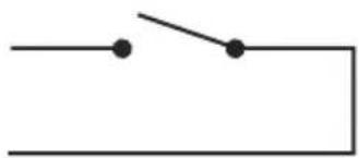
Close-up of a red electronic device with control knobs and buttons (no visible text or symbols)All of the active low signals have internal pull-ups.
Remote Inputs 1 to 10
Front Panel Inhibit Mix Mode (Pins 1 to 12)
Signal Ground (Pins 14 to 24)
natural_image
Simple electrical circuit diagram with two dots and a switch (no text or symbols)Fig 1-9: Connection Example.
Status Outputs
This 25 way D-type socket (female) connector contains the remote status tallies.
| Pin No. Signal | Name I/O Description | |
| Pin 1 REMTALL | Y1 O Internal open collector to ground for output 1 | |
| Pin 2 REMTALL | Y2 O Internal open collector to ground for output 2 | |
| Pin 3 REMTALL | Y3 O Internal open collector to ground for output 3 | |
| Pin 4 REMTALL | Y4 O Internal open collector to ground for output 4 | |
| Pin 5 REMTALL | Y5 O Internal open collector to ground for output 5 | |
| Pin 6 REMTALL | Y6 O Internal open collector to ground for output 6 | |
| Pin 7 REMTALL | Y7 O Internal open collector to ground for output 7 | |
| Pin 8 REMTALL | Y8 O Internal open collector to ground for output 8 | |
| Pin 9 REMTALL | Y9 O Internal open collector to ground for output 9 | |
| Pin 10 REMTALLY | 10 O Internal open collector to ground for output 10 | |
| Pin 11 N/C - No internal connection | ||
| Pin 12 N/C - No internal connection | ||
| Pin 13 GND - Signal ground | ||
| Pins 14 to 23 +5V O To supply up to a maximum of 100mA | ||
| Pin 24 N/C - No internal connection | ||
| Pin 25 N/C - No internal connection | ||
Fig 1-10: Status Output Pin Connections.
Pins 1 to 10 are to replicate the front panel push button indicators. An example of how to connect the signals is shown below.
Pins 11, 12, 24 and 25 have no connection inside the unit.

Fig 1-11: Connection Example.
Technical Specifications RB-SS10
Audio Specifications
Input Impedance: 20kΩ bridging
Output Impedance: <50Ω
Maximum Input Level: +28dBu
Maximum Output Level: +28dBu
Frequency Response: 20Hz to 20kHz ±0.1dB (600Ω load, ref 1kHz)
Input Gain Range: Adjustable 8dB loss to 20dB gain (L & R adjust).
Common Mode Rejection: >66dB typically
Noise: -96dB unity gain ref +8dBu
Max Headphone Output Level: +12dBu
Connections
Inputs: 4 x XLR 3 pin female (balanced, can be unbalanced)
2 x 25 way D-type socket (female) (3 stereo balanced channels on each)
Outputs: 2 x XLR 3 pin male (stereo balanced, can be unbalanced)
Remote Start I/O: 25 way D-type plug (male)
Remote Select/ Switch Inputs: 25 way D-type socket (female)
Status Outputs: 25 way D-type socket (female)
Mains Input: Filtered IEC, 110V-120V, or 220-240V switchable, fused, 6W maximum.

natural_image
Red industrial equipment panel with control knobs and buttons (no visible text or symbols)1
MIXER & SOURCE SELECTORS
SONIFEX

Equipment Type
RB-SS10: 10 way stereo analogue source selector/mixer

Physical Specifications
Dimensions (Raw): 48cm (W) x 10.8cm (D) x 4.2cm (H) (1U)
Dimensions (Boxed): 53cm (W) x 20.5cm (D) x 6cm (H)
Weight: Nett: 1.5kg Gross: 2.0kg
2 RB-DSS10 10 Way Stereo Digital Source Selector
Introduction

Fig 2-1: RB-DSS10 Front Panel.
The RB-DSS10 10 Way stereo Digital Source Selector is a 1U rack-mount which produces an AES/EBU and S/PDIF level digital audio output from 10 selectable AES/EBU or S/PDIF digital input signals. There are 10 illuminated front panel push buttons, which select and indicate the current channel selection. The selection and indication is also available through a remote connector on the rear panel. To stop accidental front panel selection there is a remote input to inhibit the front panel buttons.
The digital receivers in this unit are fully 24 bit, 96kHz capable. When an input is selected from the front panel, or remotely, the unit will attempt to capture the incoming signal on either the AES/EBU or the S/PDIF signal inputs, with priority given to the AES/EBU input. If the AES/EBU signal becomes locked while the S/PDIF signal is routed, the unit will automatically switch to the incoming AES/EBU signal.
Once the receiver has successfully locked to a digital input, the LED illuminates, the tally is made, and the audio is routed simultaneously to both the digital audio outputs and converted to analogue audio for monitoring on the front panel headphone socket. If the incoming audio signal is not present, the push button LED and remote tally flash to indicate that the incoming digital signal is missing.
The headphone output has its own volume control, which is independent of the level adjustment for the main outputs, and has a maximum output level of +12dBu.
As well as routing the selected audio signal, the unit will also route a remote signal input through the remote connector to the selected input source, for starting external audio equipment, such as a CD player.
There is a designation strip on the front panel, useful for giving the buttons a meaningful description.
The LED on the front panel is used to indicate that power is present on the unit. However, it also has a secondary role to indicate whether the selected channel is routing the AES/EBU (red LED) or S/PDIF input (amber LED).

natural_image
Close-up of a red electronic device with visible components and no readable text or symbols2
MIXER & SOURCE SELECTORS
SONIFEX

MIXER & SOURCE SELECTORS - RB-DSS10
System Block Diagram

flowchart
graph TD
    A["Remote Start I/O"] --> B["Data Selector"]
    C["Remote Select/Switch Inputs"] --> D["MCU"]
    E["Push Button Switches"] --> D
    D --> F["Data Selector"]
    F --> G["Status Outputs"]
    H["AES/EBU"] --> I["AES Receiver"]
    I --> J["Data Selector"]
    J --> K["DAC"]
    K --> L["Outputs"]
    M["S/PDIF"] --> N["AES Receiver"]
    N --> O["AES Transmitter"]
    O --> P["Outputs"]
    Q["S/PDIF Output"] --> R["AES Receiver"]
    R --> S["Data Selector"]
    S --> T["DAC"]
    T --> U["Outputs"]
    V["Volume Control"] --> K
    W["AES/EBU"] --> X["AES Transmitter"]
    X --> Y["Outputs"]
Fig 2-2: RB-DSS10 System Block Diagram.
Front Panel Indicators & Controls

Fig 2-3: RB-DSS10 Front Panel.
Power Indicator
The LED on the front panel is used to indicate that power is present on the unit. However, it also has a secondary role to indicate whether the selected channel is routing the AES/EBU or S/PDIF input:
Red indicates AES/EBU input.
Amber indicates S/PDIF input.
The LED and remote tally flash, if the incoming audio signal is not present, to indicate that the incoming digital signal is missing.
Illuminated Push Buttons
The front panel contains 10 illuminated push buttons, used for selecting a digital source. The push button illuminates when the input is selected and flashes when the selected input loses lock.
There is also a remote input to inhibit the front panel switches. When the front panel inhibit is active, pressing the front panel switches has no effect on the current channel selection.
Headphone Output
The output available on the front panel through a 14 " stereo jack socket, is designed to drive 150 mW into 32Ω to 600Ω professional headphones.
Volume Control
The headphone output has its own volume control and has a maximum output level of +12dBu.
Additional Modes
An option to set the unit in different modes of operation is available and can be configured at anytime while the unit is powered.
There are currently three modes of operation: Alternate mode, Latched mode and Protected Alternate mode: -
Alternate Mode
In this mode the channels are selected and deselected by a press of the button, as described previously.
Latched Mode
In this mode the selected channel is active only while the button is pressed. As soon as button is released the channel becomes inactive.
Protected Alternate Mode
Operates in a similar manner to the Alternate mode, but a channel cannot be turned off unless switching to another input. In other words, there will always be a channel routed to the output. NOTE: after setting this mode there will be no channel selected.
Configuring the Additional Modes
While the unit is powered, hold down the input 10 button and press the input 5 button five times. Once completed, the input 10 button will start to flash and the first 3 input

natural_image
Close-up of a red electronic device with buttons and a stylized 'SONI' logo (no readable text or symbols beyond branding)2
MIXER & SOURCE SELECTORS
SONIFEX

buttons will display the current operating mode (as shown below). To change the mode, simply press the input 10 and the buttons will indicate the newly selected mode. Once the required operating mode has been set the unit will restart within five seconds from the last button press.
| INPUT 1 button on = Alternate mode | |
| INPUT 2 button on = Latched mode | |
| INPUT 3 button on = Protected Alternate mode |
Rear Panel Connections and Operation
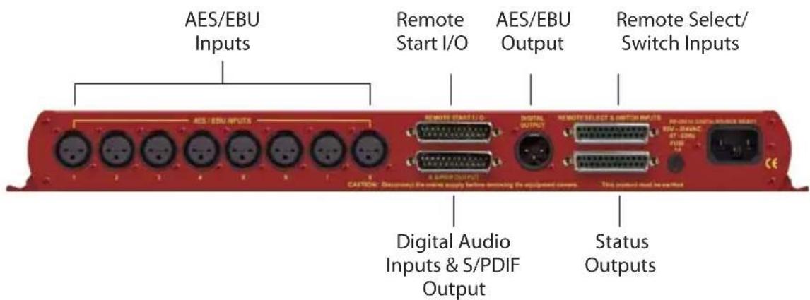
Fig 2-4: RB-DSS10 Rear Panel.
RB-DSS10 Inputs
AES/EBU Inputs
The 8 digital input XLR 3 pin sockets have an impedance of 110 . They have the following connections:
Pin 1: Screen
Pin 2: Phase
Pin 3: Non-phase
The signals on this connector should meet the IEC 60968 specification
RB-DSS10 Outputs
AES/EBU Outputs
The digital output XLR 3 pin socket has an impedance of 110Ω. It has the following connections:
Pin 1: Screen
Pin 2: Phase
Pin 3: Non-phase
The signals on these connectors will comply with the IEC 60968 specification
Digital Audio Inputs & S/PDIF Output
This connector contains the other two remaining professional AES/EBU input connections, and the 10 S/PDIF input connections. It also has the S/PDIF digital output. The S/PDIF digital inputs and the output have an impedance of 75 .
| Pin No. I/O Description | |
| Pin 1 I AES/EBU input 9 signal phase | |
| Pin 2 - Signal ground | |
| Pin 3 I AES/EBU input 10 signal non-phase | |
| Pin 4 I S/PDIF input 1 signal | |
| Pin 5 I S/PDIF input 2 signal | |
| Pin 6 I S/PDIF input 3 signal | |
| Pin 7 I S/PDIF input 4 signal | |
| Pin 8 I S/PDIF input 5 signal | |
| Pin 9 I S/PDIF input 6 signal | |
| Pin 10 I S/PDIF input 7 signal | |
| Pin 11 I S/PDIF input 8 signal | |
| Pin 12 I S/PDIF input 9 signal | |
| Pin 13 I S/PDIF input 10 signal | |
| Pin 14 I AES/EBU input 9 signal non-phase | |
| Pin 15 I AES/EBU input 10 signal phase | |
| Pins 16 to 23 - Signal ground | |
| Pin 24 O S/PDIF output signal | |
| Pin 25 - Signal ground | |
Fig 2-5: Digital Audio Inputs and S/PDIF Output Pin Connections.
Note: The actual phase of the AES/EBU signals is not relevant.

natural_image
Red industrial machine with control panel and buttons, no visible text or symbols2
MIXER & SOURCE SELECTORS
SONIFEX

natural_image
Red and orange abstract background with no visible text, numbers, or symbolsRemote Start I/O
This 25 way D-type plug (male) connector contains the remote start input connection and the corresponding 10 opto-isolated remote start outputs.
| Pin No. I/O Description | |
| Pin 1 O Start output 1 collector | |
| Pin 2 O Start output 2 collector | |
| Pin 3 O Start output 3 collector | |
| Pin 4 O Start output 4 collector | |
| Pin 5 O Start output 5 collector | |
| Pin 6 O Start output 6 collector | |
| Pin 7 O Start output 7 collector | |
| Pin 8 O Start output 8 collector | |
| Pin 9 O Start output 9 collector | |
| Pin 10 O Start output 10 collector | |
| Pin 11 - No internal connection | |
| Pin 12 - No internal connection | |
| Pin 13 I Remote start input signal | |
| Pin 14 O Start output 1 emitter | |
| Pin 15 O Start output 2 emitter | |
| Pin 16 O Start output 3 emitter | |
| Pin 17 O Start output 4 emitter | |
| Pin 18 O Start output 5 emitter | |
| Pin 19 O Start output 6 emitter | |
| Pin 20 O Start output 7 emitter | |
| Pin 21 O Start output 8 emitter | |
| Pin 22 O Start output 9 emitter | |
| Pin 23 O Start output 10 emitter | |
| Pin 24 - No internal connection | |
| Pin 25 - Signal ground | |
Fig 2-6: Remote Start Pin Connections.
These signals should be connected to external equipment, such as a CD player (as shown following). The collector connects to the start pin of the equipment, and the emitter connects to the common pin of the equipment.
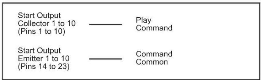
Fig 2-7: Connection Example.
Remote Select/Switch Inputs
This 25 way D-type socket (female) connector contains the front panel inhibit input connection and the remote switch inputs to control the channel selection.
| Pin No. I/O Description | |
| Pin 1 | Remote input 1 – active low | |
| Pin 2 | Remote input 2 – active low | |
| Pin 3 | Remote input 3 – active low | |
| Pin 4 | Remote input 4 – active low | |
| Pin 5 | Remote input 5 – active low | |
| Pin 6 | Remote input 6 – active low | |
| Pin 7 | Remote input 7 – active low | |
| Pin 8 | Remote input 8 – active low | |
| Pin 9 | Remote input 9 – active low | |
| Pin 10 | Remote input 10 – active low | |
| Pin 11 | Front panel inhibit signal – active low | |
| Pin 12 - No internal connection | |
| Pin 13 - No internal connection | |
| Pins 14 to 24 - Signal ground | |
| Pin 25 - No internal connection | |
Fig 2-8: Remote Select/Switch Input Connections.
All of the active low signals have internal pull-ups.

Fig 2-9: Connection Example.

natural_image
Red industrial equipment with control panels and a yellow label (no readable text or symbols)2
MIXER & SOURCE SELECTORS
SONIFEX

natural_image
Red and orange abstract background with no visible text, numbers, or symbolsStatus Outputs
This 25 way D-type socket (female) connector contains the remote status tallies.
| Pin No. Signal | Name I/O Description | |
| Pin 1 REMTALL | Y1 O Internal open collector to ground for output 1 | |
| Pin 2 REMTALL | Y2 O Internal open collector to ground for output 2 | |
| Pin 3 REMTALL | Y3 O Internal open collector to ground for output 3 | |
| Pin 4 REMTALL | Y4 O Internal open collector to ground for output 4 | |
| Pin 5 REMTALL | Y5 O Internal open collector to ground for output 5 | |
| Pin 6 REMTALL | Y6 O Internal open collector to ground for output 6 | |
| Pin 7 REMTALL | Y7 O Internal open collector to ground for output 7 | |
| Pin 8 REMTALL | Y8 O Internal open collector to ground for output 8 | |
| Pin 9 REMTALL | Y9 O Internal open collector to ground for output 9 | |
| Pin 10 REMTALL | LY10 O Internal open collector to ground for output 10 | |
| Pin 11 N/C - No internal connection | ||
| Pin 12 N/C - No internal connection | ||
| Pin 13 GND - Signal ground | ||
| Pins 14 to 23 +5V O To supply up to a maximum of 100mA | ||
| Pin 24 N/C - No internal connection | ||
| Pin 25 N/C - No internal connection | ||
Fig 2-10: Status Output Pin Connections.
Pins 1 to 10 are to replicate the front panel push button indicators. An example of how to connect the signals is shown below.
Pins 11, 12, 24 and 25 have no connection inside the unit.

Fig 2-11: Connection Example.
Technical Specifications RB-DSS10
Audio Specifications
Input Impedance: 110Ω ±20% balanced (AES/EBU)
Input Impedance: 75Ω ±5% unbalanced (S/PDIF)
Output Impedance: 110Ω ±20% balanced (AES/EBU)
Output Impedance: 75Ω ±5% unbalanced (S/PDIF)
Signal Level: 3V/10V peak to peak min/max (AES/EBU) 0.5V ±20% peak to peak (S/PDIF)
Sample Freq Range: 30-100kHz (i.e. including 32kHz, 44.1kHz, 48kHz, 64kHz, 88.2kHz and 96kHz), following input signal
Bit Depth: 16 - 24 bits, following input signal
Max Headphone Output Level: +12dBu
Audio Connections
Audio Inputs: 8 x AES/EBU XLR 3 pin female
2 x AES/EBU (part of 1 x 25 way D-type plug)
10 x S/PDIF (part of 1 x 25 way D-type plug)
Audio Outputs: 1 x AES/EBU XLR 3 pin male
1 x S/PDIF (part of 1 x 25 way D-type plug)
Other Connections
Remote Start I/O: 1 x 25 way D-type plug (male)
Remote Input Select
& Switch Inputs: 1 x 25 way D-type socket (female)
Status Outputs: 1 x 25 way D-type socket (female)
Mains Input: Filtered IEC, continuously rated 85-264VAC @ 47-63Hz, max 10W
Equipment Type
RB-DSS10
10 Way Stereo Digital Source Selector


natural_image
Close-up of a red electronic device with control knobs and buttons, no visible text or symbols2
MIXER & SOURCE SELECTORS
SONIFEX

Physical Specifications
Dimensions (Raw) 48cm (W) x 10.8cm (D) x 4.2cm (H) (1U)
Dimensions (Boxed) 53cm (W) x 20.5cm (D) x 6cm (H)
Weight Nett: 1.6kg Gross: 2.2kg
3 RB-PMX4 10 Input, 4 Output Analogue Preset Mixer
Introduction

Fig 3-1: RB-PMX4 Front Panel.
The RB-PMX4 is a high performance 10 mono input to 4 mono output preset mixer. Each of the four outputs has a 10 way DIP switch associated with it to select which of the 10 inputs are routed to it. So, by altering the DIP switches, any of the input sources can be mixed to any of the outputs. The DIP switches are enclosed by a screw-on cover on the front panel so that the settings can not be accidentally changed for secure applications.
The RB-PMX4 has been designed for situations where a small mixer is needed for installations where it will be configured and then only altered occasionally, or never altered. Uses for this product are numerous including a four bus mini-mixer, a 4 zone mixer for pubs and clubs, a multiple clean-feed generator and a quad stereo to mono converter to name a few.
The XLR-3 inputs and outputs are electronically balanced and can be wired unbalanced. Each output is individually buffered so that a short circuit on one won't affect the others. Each input has its own gain control which is a pre-set potentiometer accessible through the front panel. This provides gain adjustment of -8dB to 18db. This is useful for normalizing consumer and professional signals to give outputs of -15dBu and 0dBu respectively.
The front panel is held on by 2 off M3 x 6 stainless steel dome-head screws and can be removed using a 2mm AF hex key (allen key). Each 10-way switch represents an output and the individual switches represent the inputs that will be mixed to that output. Switches are in the ON (down) position to be mixed and the OFF (up) position for off.
The XLR-3 outputs are electronically balanced and can be wired unbalanced. Each output is individually buffered so that a short circuit on one won't affect the others.
An LED power indicator on the front panel displays the power supply connection.

natural_image
Red industrial machine with control panel and indicator lights (no visible text or symbols)
natural_image
Close-up of a red electronic device with buttons and a stylus, no visible text or symbolsMIXER & SOURCE SELECTORS - RB-PMX4
System Block Diagram

flowchart
graph TD
    A["Balanced XLR Input 1"] -->|Gain| B["Output 1 Switch Bank"]
    C["Balanced XLR Input 2"] -->|Gain| D["Output 1 Switch Bank"]
    E["Balanced XLR Input 3"] -->|Gain| F["Output 1 Switch Bank"]
    G["Balanced XLR Input 4"] -->|Gain| H["Output 1 Switch Bank"]
    I["Balanced XLR Input 5"] -->|Gain| J["Output 1 Switch Bank"]
    K["Balanced XLR Input 6"] -->|Gain| L["Output 1 Switch Bank"]
    M["Balanced XLR Input 7"] -->|Gain| N["Output 1 Switch Bank"]
    O["Balanced XLR Input 8"] -->|Gain| P["Output 1 Switch Bank"]
    Q["Balanced XLR Input 9"] -->|Gain| R["Output 1 Switch Bank"]
    S["Balanced XLR Input 10"] -->|Gain| T["Output 1 Switch Bank"]
    B --> U["Output 2 Switch Bank"]
    D --> V["Output 2 Switch Bank"]
    F --> W["Output 2 Switch Bank"]
    H --> X["Output 2 Switch Bank"]
    J --> Y["Output 2 Switch Bank"]
    L --> Z["Output 2 Switch Bank"]
    N --> AA["Output 2 Switch Bank"]
    P --> AB["Output 2 Switch Bank"]
    R --> AC["Output 2 Switch Bank"]
    T --> AD["Output 2 Switch Bank"]
    U --> AE["Output 3 Switch Bank"]
    V --> AF["Output 3 Switch Bank"]
    W --> AG["Output 3 Switch Bank"]
    X --> AH["Output 3 Switch Bank"]
    Y --> AI["Output 3 Switch Bank"]
    Z --> AJ["Output 3 Switch Bank"]
    AA --> AK["Output 3 Switch Bank"]
    AB --> AL["Output 3 Switch Bank"]
    AC --> AM["Output 3 Switch Bank"]
    AD --> AN["Output 3 Switch Bank"]
    AE --> AO["Output 3 Switch Bank"]
    AF --> AP["Output 3 Switch Bank"]
    AG --> AQ["Output 3 Switch Bank"]
    AH --> AR["Output 3 Switch Bank"]
    AI --> AS["Output 3 Switch Bank"]
    AJ --> AT["Output 3 Switch Bank"]
    AK --> AU["Output 3 Switch Bank"]
    AL --> AV["Output 3 Switch Bank"]
    AM --> AW["Output 3 Switch Bank"]
    AN --> AX["Output 3 Switch Bank"]
    AO --> AY["Output 3 Switch Bank"]
    AP --> AZ["Output 3 Switch Bank"]
    AQ --> BA["Output 3 Switch Bank"]
    AR --> BB["Output 3 Switch Bank"]
    AS --> BC["Output 3 Switch Bank"]
    AT --> BD["Output 3 Switch Bank"]
    AU --> BE["Output 3 Switch Bank"]
    AV --> BF["Output 3 Switch Bank"]
    AW --> BG["Output 3 Switch Bank"]
    AX --> BH["Output 3 Switch Bank"]
Fig 3-2: RB-PMX4 Block Diagram.
Rear Panel Connections and Operation

Fig 3-3: RB-PMX4 Rear Panel.
Inputs 1-10
The XLR-3 input sockets can take balanced professional levels, or unbalanced by using the front panel gain controls, and by connecting the non-phase to the signal ground screen. The XLR 3 pin input has the following connections:
Pin 1: Screen
Pin 2: Phase
Pin 3: Non-phase
Outputs 1-4
The XLR 3 pin output plugs are electronically balanced, and can be wired unbalanced. Each output is individually buffered so that a short circuit on one output will not affect the others. They have the following connections:
Pin 1: Screen
Pin 2: Phase
Pin 3: Non-phase
Front Panel Controls

Fig 3-4: RB-PMX4 Front Panel Controls.
Switch Banks
There are 4 off 10-way switch banks, one for each output. Using these switches, each input channel can be individually selected to each output. When the switches are up (OFF) position, they are off and mixed when in the down (ON) position.
Input Gain Controls
The gain for each input may be individually varied from -8dB to 18dB by adjusting the pre-set potentiometers, which are accessible through the holes in the front panel. This is useful for normalising consumer and professional signals to give outputs of -15dBu and 0dBu respectively.

natural_image
Red electronic device with visible ports and buttons, no readable text or symbols
Technical Specifications RB-PMX4
Audio Specifications
Maximum Input Level: +28dBu
Input Impedance: >20kΩ balanced bridging
Maximum Output Level: +28dBu
Output Impedance: <50Ω
Frequency Response: 20Hz to 20kHz ±0.1dBu (600 Ω load, @ 1kHz)
Input Gain Range: Adjustable 8dBu loss to 18dBu gain.
Common Mode Rejection: >60dBu typically
Off-isolation/Crosstalk: >90dBu @ 1kHz
Noise: -86dBu RMS 22Hz-22kHz, unity gain, ref +8dB
Distortion: <0.01% @ 1kHz, 0dBu to +26dBu
Connections
Inputs: 10 x XLR 3 pin female (Balanced, can be unbalanced)
Outputs: 4 x XLR 3 pin male (Balanced, can be unbalanced)
Mains Input: Filtered IEC, 110V-120V, or 220-240V switchable, fused, 6W maximum
Equipment Type
RB-PMX4:
10 input, 4 output analogue preset mixer
Physical Specifications
| Dimensions (Raw): | 48cm (W) x 10.8cm (D) x 4.2cm (H) (1U) |
| Dimensions (Boxed): | 53cm (W) x 20.5cm (D) x 6cm |
| Weight: | Nett: 1.5kg Gross: 2.2kg |
4 RB-SSML1 Mic/Line Source Selector with Compressor Limiter
Introduction

Fig 4-1: RB-SSML1 Front Panel.
The RB-SSML1 is a 1U rack-mountable source selector for compressing or limiting an incoming microphone or stereo line signal and mixing this signal with a stereo monitor input, which can then be metered and mixed to two headphone outputs. The unit is mainly used in situations where level control is required, for example in voiceover applications.
The mic input consists of an independent low-noise microphone pre-amplifier for converting microphone level signals to a line level. There are independent switches to control a high pass filter (low frequency roll-off at 125Hz) and to provide phantom power at +48V to the connected microphone. A preset pot on the rear panel allows adjustment of the mic gain from 36dB to 75dB.
A front panel switch selects between mic and line inputs. Both mic and line inputs have fully adjustable volume control via front panel pots, with the line input having an additional 10dB gain increase via a switch on the rear panel for use with unbalanced equipment. The mono mic input is converted to a stereo signal before being passed to the compressor/limiter.
The XLR-3 stereo monitor input has an adjustable volume control via a back panel recessed pot, and has an additional 10dB gain increase via a switch on the rear panel, for use with unbalanced equipment. The audio on this input is only present on the headphone outputs, and is therefore suitable as a return feed from a codec, a PC audio output, or similar equipment.
The compression ratio and threshold limits of the compressor/limiter section are fully adjustable via linear pots situated on the front panel. The threshold can be set between -30dBu and +20dBu. When the input signal rises above the threshold level a soft-knee compression is applied at the selected ratio. The compressor has an attack time of approximately 20ms and a release time of approx 400ms, and can operate at ratios of 1:1 (no compression) to ∞:1 (limiting). A front panel BYPASS switch can be used, where no compression is applied. A rear-panel DIPswitch allows compression only to be applied to the mic input and not the stereo line input.

natural_image
Close-up of a red electronic device with visible buttons and ports (no readable text or symbols)4
MIXER & SOURCE SELECTORS
SONIFEX

The metering is carried out after the compressor/limiter section and consists of two rows of 12 round LEDs showing levels between -17dB and +11dB. An internal jumper allows the metering to follow either the stereo output, or the headphone monitor outputs and a rear panel DIPswitch can disable the peak hold display.
The XLR-3 stereo line output can be fed from either the mic or line input, but not the stereo monitor input. The line output is electronically balanced and can be wired unbalanced by grounding the non-phase signal, allowing you to feed both balanced and unbalanced equipment. A pushbutton switch is provided to reduce the output by 10dB for this purpose.
The headphone output volume control is on the front panel. Each headphone output is designed to drive 150 mW into 32Ω to 600Ω stereo headphones.
An LED power indicator on the front panel displays the power supply connection.
System Block Diagram

flowchart
graph TD
    A["Phantom Power (48V)"] --> B["Gain Phantom On/Off"]
    B --> C["L.F. Filter In/Out"]
    C --> D["Mic. Volume"]
    D --> E["Threshold Compression"]
    E --> F["Analogue Switch"]
    F --> G["Fixed Gain"]
    G --> H["Stereo Output"]
    I["Stereo Line"] --> J["Fixed Gain"]
    J --> K["Line Volume L"]
    K --> L["Line Volume R"]
    L --> M["Compressor Controls"]
    M --> N["Jumper"]
    N --> O["LED Level Meter Drivers"]
    P["Stereo Monitor"] --> Q["Fixed Gain"]
    Q --> R["Line Volume L"]
    R --> S["Line Volume R"]
    S --> T["Audio Output Amplifier"]
    T --> U["Stereo Jack Output"]
    V["Audio Output Amplifier"] --> W["Volume"]
    W --> X["Peak Hold On/Off"]
    Y["Audio Output Amplifier"] --> Z["Audio Output Amplifier"]
Fig 4-2: RB-SSML1 Block Diagram.
Rear Panel Connections

Fig 4-3: RB-SSML1 Rear Panel.
Stereo Monitor Inputs
The 2 x XLR 3 pin sockets used for the monitor input are electronically balanced. They have the following connections:
Pin 1: Screen
Pin 2: Phase
Pin 3: Non-phase
Note: The monitor input can not be mixed to the stereo line output, it is only used for headphone monitoring.
Stereo Monitor Pad & Volume Control
A 10dB gain pad is available by depressing the rear panel switch, for handling connection from unbalanced outputs. A MONITOR VOLUME control is available as a pre-set potentiometer, located on the back panel. The monitor input channel with the volume control fully up, has a gain of +6dB.
Mic Input
The XLR 3 pin socket used for the microphone is electronically balanced. It has the following connections:
Pin 1: Screen
Pin 2: Phase
Pin 3: Non-phase
Mic Input Gain
A recessed GAIN pre-set potentiometer allows for adjustment of the gain of the microphone input. This provides a gain range of 36dB to 75dB which enables the use of dynamic and powered microphones. Connect the mic input and adjust the gain until the line output is at the required level. The front panel MIC VOLUME reduces the volume to -80dB.
Using Phantom Powered Microphones
For the microphone input channel there is a switch to provide phantom power at +48V to the connected microphone. With phantom power selected, a voltage of +48V is applied to pins 2 and 3 of the XLR connector to power the microphone, supplied through 6k8 resistors giving a current of 14mA. Phantom power is enabled when the switch is pointing towards the arrow.

1 Low Frequency (LF) Filter
2 Phantom Power
3 Compress In Mic Mode Only
4 LED Meter Peak Hold
Fig 4-4: DIP Switch to Control Mic & Meter Features.

natural_image
Red industrial machine with control panel and indicator lights (no visible text or symbols)4
MIXER & SOURCE SELECTORS
SONIFEX

natural_image
Red and orange abstract background with blurred circular patterns and no visible text or symbolsUsing the LF Filter
This switch provides control for a high pass filter on the mic input with low frequency roll off at 125Hz. The roll-off filter is in circuit when the switch is down (towards the arrow).
Compression Active on Mic Input Only
With this feature enabled, the compressor/limiter will only operate when the microphone input is selected. This mode becomes active when switch 3 is down (towards the arrow).
Peak Hold Disabled on LED Meter
By default, the LED meter operates with peak hold active on the top 5 segments. This can be disabled by moving switch 4 to the up position (towards the arrow).
Stereo Line Input
The 2 x XLR 3 pin sockets used for the line input are electronically balanced. They have the following connections:
Pin 1: Screen
Pin 2: Phase
Pin 3: Non-phase
Stereo Input Gain Pad
The line input channel with the volume control fully up, has a gain of +6dB. An extra 10dB of gain is available by depressing the rear panel INPUT LEVEL switch. The LINE VOLUME control is located on the front panel.
Stereo Line Output
The XLR 3 pin plug output connectors are electronically balanced and can be wired unbalanced by grounding the non-phase signal, allowing you to feed balanced and unbalanced equipment. They have the following connections:
Pin 1: Screen
Pin 2: Phase
Pin 3: Non-phase
The connector provides a line level output with an impedance of <50 and a maximum output level of +28dBu.
Stereo Output Gain Pad
The output gain switch provides a 10dB drop in gain.
Front Panel Controls

Fig 4-5: RB-SSML1 Front Panel.
Mic & Line Volume Controls
The front panel MIC VOLUME reduces the volume to -80dB. The line input channel with the LINE VOLUME control fully up, has a gain of +6dB.
Mic/Line Select Switch
To select between microphone or stereo line inputs, use the Mic/Line select switch; stereo line is in the up position.
Bypass Button
The compressor/limiter section of the product can be switched in and out by using the BYPASS button.
Applying Compression
Compression is applied by setting a threshold at which the compressor begins to operate, and a compression ratio to which all audio above the threshold will be compressed. To enable the compressor, release the unit from bypass mode (ensure the bypass LED is off).
The compression ratio and threshold limits of the compressor/limiter section are fully adjustable via the COMPRESSION and THRESHOLD linear pots situated on the front panel. The threshold can be set between -30dBu and +20dBu. When the input signal rises above the threshold level a soft-knee compression is applied at the selected ratio. The compressor has an attack time of approximately 20ms and a release time of approx 400ms, and can operate at ratios of 1:1 (no compression) to ∞:1 (limiting).
The compressor is temperature sensitive and in cold conditions may take a short time for the threshold levels to settle. In any case you should always allow the unit to fully come to its normal operating temperature before setting the threshold level.
LED Metering
The metering is carried out after the compressor/limiter section and consists of two rows of 12 round LEDs showing levels between -17dB and +11dB.
The LED meter source can be set to either the output, or a mix of the output and the monitor input (i.e. the audio present on the headphones). The default setting is a mix of the output and monitor input. This can be changed by altering the setting of jumpers J1 and J2 inside the unit.
Position A: Meter a mix of output and monitor input.
Position B: Meter output only.
Headphone Outputs
There are two 14 " stereo jack headphone sockets, with a headphone output volume control which controls the volume for both outputs. Each headphone output is designed to drive 150mW into 32Ω to 600Ω stereo headphones.

natural_image
Close-up of a red electronic device with buttons and a stylized 'SONI' logo (no readable text or symbols beyond branding)4
MIXER & SOURCE SELECTORS
SONIFEX

Technical Specifications RB-SSML1
Audio Specifications (Bypass Mode)
Maximum Input Level: -10dBu (mic), +28dBu (line), electronically balanced
Input Impedance: 20kΩ nominal balanced
Maximum Output Level: +28dBu
Output Impedance: <50Ω
Headphone Output Level: Drives 150mW into 32Ω to 600Ω headphones
Low Frequency Roll-Off: 125Hz @ 6dB/octave
Gain Range (mic): Adjustable 36dB to 75dB gain (-80dB volume min.)
Volume Control (line): -80dB to +6dB gain (+16dB with additional input gain)
E.I.N: 130dB
Distortion: <0.02% THD @ 1kHz, ref +8dBu output
Common Mode Rejection: >66dB typically
Phantom Power: 48V
Frequency Response: 20Hz to 20kHz ±0.3dB (600Ω load, ref 1kHz)
Connections
| Mic Input: | 1 x XLR 3 pin female (Balanced) |
| Stereo Line Input: | 2 x XLR 3 pin female (Balanced, can be unbalanced) |
| Stereo Monitor Input: | 2 x XLR 3 pin female (Balanced, can be unbalanced) |
| Stereo Output: | 2 x XLR 3 pin male (Balanced, can be unbalanced) |
| Headphone Outputs: | 2 x 14 " (6.35mm) A/B gauge 3-pole stereo jack sockets |
| Mains Input: | Filtered IEC, 110V-120V, or 220-240V switchable, fused, 9W maximum |
Equipment Type
RB-SSML1: Mic/Line source selector with compressor limiter
Physical Specifications
| Dimensions (Raw): | 48cm (W) x 10.8cm (D) x 4.2cm (H) (1U) |
| Dimensions (Boxed): | 53cm (W) x 20.5cm (D) x 6cm (H) |
| Weight RB-SSML1: | Nett: 1.30kg Gross: 2.00kg |
5 RB-MA1 Single & RB-MA2 Dual Microphone Amplifiers
Introduction

Fig 5-1: RB-MA1 & RB-MA2 Front Panel.
The RB-MA1 consists of an independent low-noise microphone pre-amplifier for converting microphone level signals to line level, or for driving long lines from microphones to mixing equipment. The RB-MA2 dual microphone amplifier consists of two low noise pre amplifiers.
All connections and controls are on the rear panel. The microphone input is XLR-3 type and is electronically balanced. The input gain can be adjusted individually by a recessed pre-set potentiometer.
The XLR-3 line output is electronically balanced and can be wired unbalanced by grounding the non-phase signal, allowing you to feed both balanced and unbalanced equipment.
For each channel there are independent switches to control a high pass filter (low frequency roll-off at 125Hz) and to provide phantom power at +48V to the connected microphone. An LED power indicator on the front panel displays the power supply connection.
The rest of this chapter will refer to both RB-MA1 and RB-MA2 unless stated otherwise.
System Block Diagram

flowchart
graph LR
    A["Balanced Microphone Input"] --> B["Ultra low noise high gain amplifier"]
    B --> C["L.F. Filter"]
    C --> D["Professional balanced output"]
    E["Phantom power (48V)"] --> F["48V"]
    F --> G["Gain"]
    G --> B
    H["L.F. Filter in/out"] --> C
    I["Phantom supply on/off"] --> F
Fig 5-2: RB-MA1 & RB-MA2 Block Diagram Single Channel.

natural_image
Red industrial machine with control panel and buttons (no visible text or symbols)5
MICROPHONE AMPLIFIERS & LIMITERS

natural_image
Red and orange abstract image with no visible text, numbers, or symbolsRear Panel Connections and Operation

Fig 5-3: RB-MA1 Rear Panel.
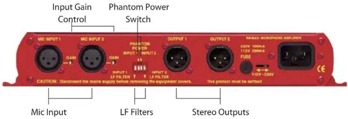
Fig 5-4: RB-MA2 Rear Panel.
Mic Inputs
The XLR 3 pin sockets used for the microphone are electronically balanced. They have the following connections:
Pin 1: Screen
Pin 2: Phase
Pin 3: Non-phase
Input Gain
Recessed pre-set potentiometers allow for adjustment of the gain of the microphone inputs. This provides a gain range of 36dB to 75dB which enables the use of dynamic and powered microphones. Connect the mic input and adjust the gain until the line output is at the level that you need.

1 Channel 1 Low Frequency (LF) Filter
2 Channel 1 Phantom Power
3 Channel 2 Phantom Power (only applies to MA2)
4 Channel 2 Low Frequency
Fig 5-5: Switch to Control LF Filter and Phantom Power.
Using Phantom Powered Microphones
For the input channel there are independent switches to provide phantom power at +48V to the connected microphones. With phantom power selected, a voltage of +48V is applied to pins 2 and 3 of the XLR connector to power the microphone, supplied through 6k8 resistors giving a current of 14mA. Phantom power is used when the switch is pointing towards the arrow.
Using the LF Filter
A switch also provides control for a high pass filter with low frequency roll off at 125Hz. The filter is in when the switch is in the down position (towards the arrow).
Output
The XLR 3 pin plug output connector is electronically balanced and can be wired unbalanced by grounding the non-phase signal, allowing you to feed balanced and unbalanced equipment. It has the following connections:
Pin 1: Screen
Pin 2: Phase
Pin 3: Non-phase
The connector provides a line level output with an impedance of <50 and a maximum output level of +28dBu.

natural_image
Red industrial machine with control panel and indicator lights (no visible text or symbols)5
MICROPHONE AMPLIFIERS & LIMITERS

Technical Specifications RB-MA1 & RB-MA2
Audio Specifications
Maximum Input Level: -10dBu
Maximum Output Level: +28dBu
Input Impedance: 20kΩ nominal balanced
Output Impedance: <50Ω
Low Frequency Roll-Off: 125Hz @ 6dB/octave
Gain Range: Adjustable 36dB to 75dB gain
E.I.N: 130dB
Distortion: 0.01% THD @ 1kHz, ref +8dBu output
Common Mode Rejection: >66dB typically
Phantom Power: 48V
Frequency Response: 20Hz to 20kHz ±0.1dB (600Ω load, ref 1kHz)
Connections
Input: 1 (2 on RB-MA2) x XLR 3 pin female (Balanced)
Output: 1 (2 on RB-MA2) x XLR 3 pin male (Balanced, can be unbalanced)
Mains Input:
Filtered IEC, 110V-120V, or 220-240V switchable, fused, 6W maximum
Equipment Type
RB-MA1:
Single microphone amplifier
RB-MA2:
Dual microphone amplifier


Physical Specifications
Dimensions (Raw): 28cm (W) x 10.8cm (D) x 4.2cm (H) (1U)
Dimensions (Boxed): 36cm (W) x 20.5cm (D) x 6cm (H)
Weight RB-MA1:
Nett: 0.90kg
Gross:
1.35kg
Weight RB-MA2:
Nett: 1.00kg
Gross:
1.45kg
6 RB-DMA2 Dual Digital Microphone Amplifier
Introduction

Fig 6-1: RB-DMA2 Front Panel.

The RB-DMA2 consists of two independent low-noise microphone pre-amplifiers for converting microphone level signals to digital AES/EBU, or S/PDIF, and analogue line level outputs. The RB-DMA2 can be used as a front end for digital mixing desks or routers, which do not have microphone inputs. The analogue outputs can be used for routing to talkback systems.
The microphone inputs are XLR-3 type and are electronically balanced. The input gain for each input can be adjusted individually by coarse and fine gain controls on the front panel and each input has a level indicator. Additionally the fine gain control knob can be disabled by internal jumpers. A switch on the rear panel allows input 1 to be routed to both left and right digital outputs, or as input 1 to left output and input 2 to right output respectively.
For each channel there are independent switches to control a high pass filter (low frequency roll-off at 125Hz) and to provide phantom power at +48V to the connected microphones. It also has AES/EBU, S/PDIF and Word Clock sync inputs.
The unit operates in four modes:
Master Mode - In this mode the unit receives a microphone-input signal, which is digitised and formatted for digital serial transmission (IEC958). The necessary clock signals are generated internally from an on board master clock at a selectable rate (32kHz, 44.1kHz, 48kHz, 64kHz, 88.2kHz or 96kHz).
Slave Mode - In this mode the unit automatically detects the presence of a digital audio sync signal, if present at the digital input or word clock input, and synchronises the digital output to it. If no sync is present, no output will be generated.
Auto Mode - Here the unit synchronises to the digital audio sync signal if present at the digital input and uses the internal master clock only if no sync input signal is detected. In this case, the internal master clock is used at the selected sample rate.
Auto Lock Mode - This operates like the auto mode except that if no sync-input signal is detected, it will use the internal master clock to sync to the sample rate which was last clocked to. When operating in sync modes, the front panel power LED flashes whenever the unit is not synchronised to the incoming digital signal, or when the unit is being calibrated. The unit should be calibrated once it has been powered up for more than 10 minutes.

natural_image
Red industrial machine with control panel and buttons, no visible text or symbols6
MICROPHONE AMPLIFIERS & LIMITERS

For the digital output, there is a switch available to define the content of the channel status bits embedded within the digital audio stream. The channel status bits will be forced to Professional Mode for sample rates above 48kHz, as they are not supported by the Consumer Mode. For sample rates of 32kHz, 44.1kHz and 48kHz, the status bits can be either set to Professional or Consumer Mode.
The bit depth of the digital output can be set to 16, 20 or 24 bits, with a psycho acoustic noise filter used to dither signals below 24 bit.
System Block Diagram

flowchart
graph TD
    A["1 Balanced Mic Inputs"] --> B["LF Filter"]
    B --> C["Gain Control"]
    C --> D["48V Phantom Power"]
    E["2 Balanced Mic Inputs"] --> F["LF Filter"]
    F --> G["Gain Control"]
    G --> H["ADC"]
    H --> I["AES Transmitter"]
    I --> J["Digital Send Select"]
    J --> K["AES/EBU S/PDIF"]
    L["Word Clock"] --> M["Digital Sync Inputs"]
    N["AES/EBU S/PDIF"] --> M
    O["Recovered Clock"] --> P["AES Receiver"]
    P --> Q["Master Clock Generator"]
    Q --> R["Frequency Select"]
Fig 6-2: RB-DMA2 System Block Diagram.
Front Panel Indicators & Controls

Fig 6-3: RB-DMA2 Front Panel.
Sync & Power Indicator
The LED on the front panel is normally red to indicate that power is present on the unit. However, it also has a secondary role to indicate the status of the digital inputs: Fast flashing between red and amber indicates a loss of digital input signal, or that the unit is being calibrated.
Input Level Adjustment
Front panel potentiometers, coarse and fine, allow for adjustment of the gain of each microphone input. The recessed screw-head potentiometer coarse control provides a total gain range of 44dB, with the level knob fine control providing a ±12dB adjustment.
Connect the mic input and adjust the gain until the line output is at the level that you need. The wide gain range allows the use of both dynamic and powered microphones.
Disabling the Fine Gain Control Knob
Each fine control also has the ability to be disabled via a jumper (JP1 for MIC1 and JP2 for MIC2) situated on the PCB. When the jumper is fitted the control is enabled.

flowchart
graph TD
    A["JP1"] --> B["Component 1"]
    B --> C["Component 2"]
    C --> D["JP2"]
    style A fill:#f9f,stroke:#333
    style B fill:#ccf,stroke:#333
    style C fill:#cfc,stroke:#333
    style D fill:#fcc,stroke:#333
Fig 6-4: Jumpers to Disable Fine Gain Control.
Input Level Indicators
For each input there is a tri-colour LED to give an indication of the level of the incoming mic signals. Green indicates -18dBFS, orange indicates -12dBFS and red indicates -6dBFS.
Rear Panel Connections and Operation
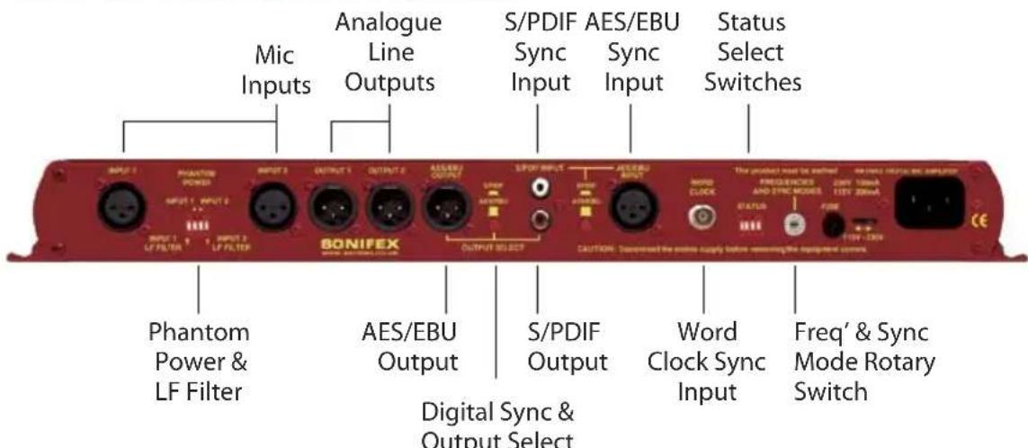
Fig 6-5: RB-DMA2 Rear Panel.

natural_image
Red industrial machine with control panel and buttons, no visible text or symbols6
MICROPHONE AMPLIFIERS & LIMITERS

natural_image
Red industrial machine with control panel and indicator lights (no visible text or symbols)RB-DMA2 Inputs
Mic Inputs
The XLR 3 pin sockets used for the microphone inputs are electronically balanced. They have the following connections:
Pin 1: Screen
Pin 2: Phase
Pin 3: Non-phase
AES/EBU Sync Input
The digital AES/EBU synchronisation input XLR 3 pin socket has an impedance of 110 and the signals meet the IEC 60968 specification. It has the following connections:
Pin 1: Screen
Pin 2: Phase
Pin 3: Non-phase
Word Clock Sync Input
The BNC TTL word clock input has an impedance of 50 Ω.
S/PDIF Sync Input
The S/PDIF digital phono input has an impedance of 75 Ω.
RB-DMA2 Outputs
AES/EBU Output
The digital output XLR 3 pin socket has an impedance of 110Ω and the signals on this connector comply with the IEC 60968 specification. It has the following connections :
Pin 1: Screen
Pin 2: Phase
Pin 3: Non-phase
S/PDIF Output
The digital output S/PDIF phono output has an impedance of 75Ω.
Analogue Line Outputs
There is an analogue output on XLR 3 pin plug for each microphone input. The plug has the following connections:
Pin 1: Screen
Pin 2: Phase
Pin 3: Non-phase
Rear Panel Controls
Status Select Switches
These switches are used to determine the status or content of the digital output signals. The type of information encoded in the channel status bits of a digital audio signal can be professional or consumer and is determined by switch 1. However at frame rates higher than 48kHz, consumer mode is not available, so professional mode is used and this switch will be ignored.
The sample size for the analogue to digital conversion can be set to 24, 20 or 16 bits (switches 3 & 4). When the signal is truncated from 24 bits, a psycho-acoustic filter is applied to maintain optimum signal quality. These settings are summarised below and also on the top panel of the unit.
| Status Bits | ||
| 1 ON | N Professional | 16 20 24 |
| 1 OFF | Con | sumer 3 OFF ON ON |
| 2 ON | Dual | Mono 4 OFF OFF ON |
| 2 OFF | Mono | |
Fig 6-6: RB-DMA2 Status Select Switches.
Output Routing
This uses switch 2 of the STATUS dipswitch block. When switch 2 is "ON", the audio signal from Mic input 1 is copied to both channels of the digital output signal (channel B = channel A) and Mic input 2 is ignored (Dual mono mode). When "OFF", the Mic input 1 signal is on channel A only of the digital output signal and channel B contains the Mic input 2 signal (Mono mode).
Note: This does not affect the routing of the analogue outputs.
Phantom Power & LF Filter
For each channel there are independent switches to provide phantom power at +48V to the connected microphones. With phantom power selected, a voltage of +48V is applied to pins 2 and 3 of the XLR connector to power the microphone, supplied through 6k8 resistors giving a current of 14mA. Phantom power is used when the switches are towards the arrows.
The LF filter switches provide control for a high pass filter with low frequency roll off at 125Hz. The roll-off filters are switched "in" when the switches are in the down position (towards the arrows).

natural_image
Red industrial machine with control panel and indicator lights (no visible text or symbols)6
MICROPHONE AMPLIFIERS & LIMITERS

natural_image
Red and black industrial equipment with no visible text or symbolsDigital Sync & Output Select Buttons
These buttons are used to switch the digital connection between the AES/EBU XLR connector (button out) and the S/PDIF phono connector (button in) independently for the digital sync input and the digital output.
Note: There is no switch to select the Word Clock as a sync input. The unit automatically searches for a sync signal on the Word Clock, or the selected digital input, and automatically locks to a valid sync clock.
Frequency and Sync Mode Rotary Switch
This rotary switch is used to select the Synchronisation Mode and to select the frequency of the digital output when using the on-board clock generator. There are 4 modes of operation: - Master Mode, Auto Sync Mode, Auto Lock Sync Mode & Slave Mode.
- In Master Sync Mode, switch positions 0 – 5, the digital output sample rate is simply set by, and locked to, the internal on-board clock generator. No sync signal is used or required.
- In Auto Sync Mode, switch positions 6–B, the digital output sample rate follows the digital input. When the digital input signal is not present the output sample rate will be set by, and locked to, the internal on-board clock generator at a frequency determined by the switch position.
- In Auto-Lock Sync Mode, switch position C, No output will be generated until lock is achieved with a digital input signal. The digital output sample rate now follows the digital input. If the digital input signal is removed then the output sample rate will be set by, and locked to, the internal on-board clock generator at the closest frequency available to the previous digital input.
- In Slave Sync Mode, switch position D, the digital output sample rate follows the digital input. When the digital input signal is not present the digital output is turned off.
The following table, also printed on the top of the unit, summarises the above settings and shows the sample rate generated by the internal clock generator in master and auto sync modes.
| Frequencies and Sync Modes | ||
| Rotary Switch Number | Mode Sample | Frequency (kHz) |
| 0 Master 32 | ||
| 1 Master 44.1 | ||
| 2 Master 48 | ||
| 3 Master 64 | ||
| 4 Master 88.2 | ||
| 5 Master 96 | ||
| 6 Auto 32 | ||
| 7 Auto 44.1 | ||
| 8 Auto 48 | ||
| 9 Auto 64 | ||
| A Auto 88.2 | ||
| B Auto 96 | ||
| C Auto Lock - | ||
| D Slave - | ||
| F Calibration - | ||
Fig 6-7: RB-DMA2 Frequency and Sync Rotary Switch Selections.
Test/Calibration Mode
For optimum performance of the RB-DMA2, the unit should be calibrated when it has been powered up for approximately 10-15 minutes. The circuitry and chipsets contained in the unit will warm up during this time and the performance will deteriorate unless calibrated (the noise floor and dynamic range will be 1-2dB lower than the best possible performance). The calibration cycle calibrates the gain and the zero reference of the A/D converter.
To calibrate the RB-DMA2, set the rotary FREQUENCIES AND SYNC MODES switch to position "F". The power LED on the front panel will flash quickly for 2 – 3 seconds and will illuminate fully when the unit is calibrated. Once calibration is complete, reset the rotary switch to the position that you require.

natural_image
Red industrial equipment with control panel and buttons, no visible text or symbols
Technical Specifications RB-DMA2
Connections
Analogue Mic Inputs: 2 x XLR 3 pin (balanced)
Analogue Line Outputs: 2 x XLR 3 pin (balanced)
Digital Sync Inputs: 1 x AES/EBU XLR 3 pin female
1 x S/PDIF RCA phono
1 x TTL BNC female (sync) 50 ohm impedance
Digital Outputs: 1 x AES/EBU XLR 3 pin plug
1 x S/PDIF RCA phono socket
Mains Input: Filtered IEC, 110-120V, or 220-240V switchable, fused 10W max
Audio Specification
Min/Max Input Level: -63dBu / 5dBu to give FSD
Input Impedance: 2kΩ nominal balanced
Gain Range: 68dB
Signal to Noise: 128dB EIN
Dynamic Range: >110dB
Distortion and Noise: < 0.01% THD + N absolute @ 1kHz
Phantom Power: +48V
Low Frequency Roll-off: 125Hz @ 6dB/octave
Analogue Output Level: +18dBu Ref. FSD
Operational Controls & Indicators
Bit Depth: 16, 20 or 24 bits via DIP switch
Digital Output Select: AES/EBU or S/PDIF, via push-switch
Sample Frequencies: 32kHz – 96kHz, via rotary switch
Sync Modes: Master, Slave, Auto, Auto-Lock via rotary switch
Digital Input Select: AES/EBU or S/PDIF, via push-switch
Channel Status Bits: Set to consumer or professional mode via DIP switch
Output Routing: Set dual mono output via dipswitch
Led Level: Green ind. -18dBFS, Orange ind. -12dBFS, Red ind. -6dBFS
Equipment Type
RB-DMA2 Dual Digital Microphone Amplifier

Physical Specifications
Dimensions (Raw): 48cm (W) x 10.8cm (D) x 4.2cm (H)(1U)
Dimensions (Boxed): 53cm (W) x 20.5cm (D) x 6cm (H)
Weight: Nett: 1.6kg Gross: 2.2kg

natural_image
Red and orange abstract background with blurred geometric shapes and no visible text or symbols7
MICROPHONE AMPLIFIERS & LIMITERS
SONIFEX

natural_image
Red industrial machine with control panel and indicator lights (no visible text or symbols)7 RB-ML2 Stereo Microphone & Line Level Limiter
Introduction

Fig 7-1: RB-ML2 Front Panel.
The RB-ML2 is a stereo microphone and line level limiter. The unit is mainly used where assistance with level control is required, for protection of mixer inputs and to prevent distortion. The RB-ML2 is ideal for news-booths, and the input to PC work stations, it provides an economical level control solution.
The RB-ML2 has two electronically balanced XLR-3 inputs, which are routed to a line amplifier, or microphone amplifier, via a rear push-button. The microphone amplifiers have independent pre-set gain controls, and DIP switches for a high pass filter (low frequency roll-off at 125Hz) and phantom power to provide +48V to the connected microphones.
The outputs of these amplifiers are passed through a VCA limiter circuit that can operate jointly on the signals in stereo mode, or independently in dual mono mode. The rear panel mode switch changes the unit from dual mono to stereo.
The two XLR-3 electronically balanced outputs can be set to either line or mic output levels via a push button. This allows the RB-ML2 to be used in line with a line or mic input on a mixer, or similar equipment
System Block Diagram

flowchart
graph LR
    subgraph Branch1
        A["Phantom Power (48V)"] --> B["Gain"]
        C["Line 1"] --> D["Gain"]
        E["Line 1"] --> F["Gain"]
    end

    subgraph Branch2
        G["Phantom Power (48V)"] --> H["Gain"]
        I["Line 1"] --> J["Gain"]
        K["Line 1"] --> L["Gain"]
    end

    A --> M["LF Filter"]
    C --> N["Limiter Stage"]
    D --> O["Gain and Limit Control"]
    F --> P["Gain and Limit Control"]
    H --> Q["Limiter Stage"]
    J --> R["Gain and Limit Control"]
    L --> S["Limiter Stage"]
    M --> T["Mic/Line Output"]
    N --> U["Mic/Line Output"]
    P --> V["Mic/Line Output"]
    Q --> W["Mic/Line Output"]
    R --> X["Mic/Line Output"]
    S --> Y["Mic/Line Output"]
Fig 7-2: RB-ML2 Block Diagram.
Rear Panel Connections and Operation
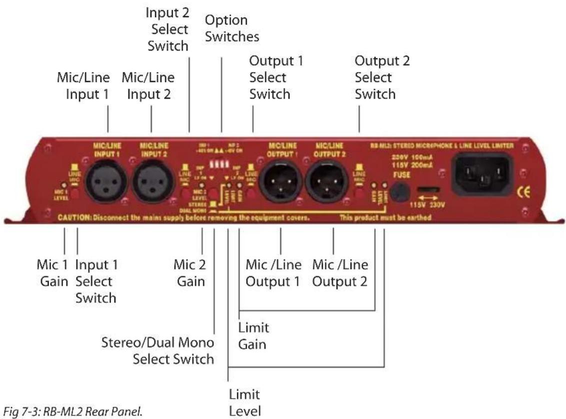

natural_image
Red industrial control panel with buttons and gauges, no visible text or symbols7
MICROPHONE AMPLIFIERS & LIMITERS

Mic / Line Inputs
The XLR 3 pin sockets used for the mic/line inputs are electronically balanced. They have the following connections:
Pin 1: Screen
Pin 2: Phase
Pin 3: Non-phase
Mic Input Gain
Recessed pre-set potentiometers allow for adjustment of the gain of the microphone inputs. This provides a gain range of +22dB to +67dB which enables the use of dynamic and powered microphones. Connect the mic input and adjust the gain until the line output is at the level that you need.

1 Channel 1 Low Frequency (LF) Filter
2 Channel 1 Phantom Power
3 Channel 2 Phantom Power
4 Channel 2 Low Frequency
Fig 7-4: Switch to Control LF Filter and Phantom Power.
Using Phantom Powered Microphones
For the mic input channel there are independent switches to provide phantom power at +48V to the connected microphones. With phantom power selected, a voltage of +48V is applied to pins 2 and 3 of the XLR connector to power the microphone, supplied through 6k8 resistors giving a current of 14mA. Phantom power is used when the switch is pointing towards the arrow. The phantom power only applies when the input is set to mic mode.
Using the LF Filter
A switch also provides control for a high pass filter with low frequency roll off at 125Hz. The filter is in when the switch is in the down position (towards the arrow). The filter only applies when the input is set to mic mode.
Mic / Line Outputs
The XLR 3 pin plug output connector is electronically balanced and can be wired unbalanced by grounding the non-phase signal, allowing you to feed balanced and unbalanced equipment. It has the following connections:
Pin 1: Screen
Pin 2: Phase
Pin 3: Non-phase
The connector provides a line level output with an impedance of <50 in line mode and 150 in mic mode, with a maximum output level of -18dBu(mic) or +28 dBu(line).
Mic / Line Output Gain
The output gain is adjustable from -54dB to -24dB when mic is selected and adjustable between -8dB to +22dB for line, with reference to 0dBu line input. The gain is adjusted via two potentiometers on the rear panel of the unit, although it is pre-set in production.
Level Limiting
Stereo limiting operates by limiting both left and right outputs if either the left and right input needs to be limited. Dual mono limiting operates by limiting left and right signals individually.
The characteristics of the limiter can be set via level threshold pre-sets. For each channel there is an input gain and a threshold level control. With the limit threshold set to maximum, the input through to output can be normalised using the input potentiometers. Once the unit is acting as a buffer with gain/attenuation, the limit threshold level can be set, with the recovery adjusted for the application. The power LED indicates limiting by flashing.
Mode Select Switch
The mode switch changes the unit from dual mono to stereo mode. In stereo mode, only the pre-sets for channel 1 (left) are active and they are applied to both channels. Stereo limiting operates by limiting both left and right outputs if either left or right input needs to be limited. Dual mono limiting operates by limiting left and right signals individually – you can use the RB-ML2 as two separate mono limiters.

natural_image
Close-up of a red electronic device with buttons and a stylized 'SONI' logo (no readable text or symbols beyond branding)7
MICROPHONE AMPLIFIERS & LIMITERS

Technical Specifications RB-ML2
Audio Specifications
Maximum Input Level: -6dBu (mic), +28dBu (line), electronically balanced
Input Impedance: >20kΩ balanced bridging
Input Gain Range: Adjustable +22dB to +67dB gain (mic)
Via 2 x pre-set potentiometers (L&R), 0dB gain (line)
Maximum Output Level: -18dBu (mic), +28dBu (line), electronically balanced
Output Impedance: 150Ω(mic), <50Ω balanced (line)
Output Gain Range: -8dB to +22 dB gain (line), ref 0dBu line input
Gain via 2 x pre-set potentiometers
Limit Threshold: Adjustable -8dBu to +28dBu
Frequency Response: 20Hz to 20 kHz +/- 0.1dB (600 ohm load, ref 1kHz)
E.I.N: 130dB
Distortion: <0.02% THD @ 1kHz, ref +8dBu output
Common Mode Rejection (mic): >86dB typically
Common Mode Rejection (line): >66dB typically
Phantom Power: 48V
LF Filter: 125Hz@6dBs/octave
Connections
| Analogue Input: (Balanced)(L &R) | 2 x XLR 3 pin female mic or line switchable |
| Mic/Line Input Control: | 2 x push-buttons for mic/line inputs |
| Analogue Outputs: | 2 x XLR 3 pin male or line switchable(Balanced)(L&R) |
| Mic/Line Output Control: | 2 x push-button for mic/line outputs |
| Phantom Power & LF Filter: | 1x 4-way DIP switch |
| Mono/Stereo Mode select: | 1 x push button |
| Limit Level Threshold Set: | 2 x pre-set potentiometers |
| Mains Input: | Filtered IEC, 110V-120V, or 220-240V switchable, fused, 6W maximum |
Equipment Type
RB-ML2: Stereo Microphone & Line Level Limiter

Physical Specifications
Dimensions (Raw): 28cm (W) x 10.8cm (D) x 4.2cm (H) (1U)
Dimensions (Boxed): 36cm (W) x 20.5cm (D) x 6cm (H)
Weight RB-ML2: Nett: 0.90kg Gross: 1.35kg

natural_image
Red and orange abstract background with no visible text, numbers, or symbols8
MICROPHONE AMPLIFIERS & LIMITERS
SONIFEX

Fig 8-1: RB-SL2 Front Panel.
The RB-SL2 is a stereo, or twin independent mono, VCA limiter for use in news-rooms and other locations where the correct level into recording equipment is required, but not necessarily under the control of an engineer, for example, for overload protection. It can also be used as an inexpensive main output limiter for low cost radio installations, RSL's, hospital and student radio.
The XLR-3 electronically balanced inputs and outputs can be wired unbalanced to accept an output from domestic equipment. For each channel there is an input gain and a threshold level control.
A rear panel switch changes the unit from dual mono to stereo, when only the pre-sets for channel 1 (left) are active and apply to both channels. An LED power indicator on the front panel displays the power supply connection.
System Block Diagram
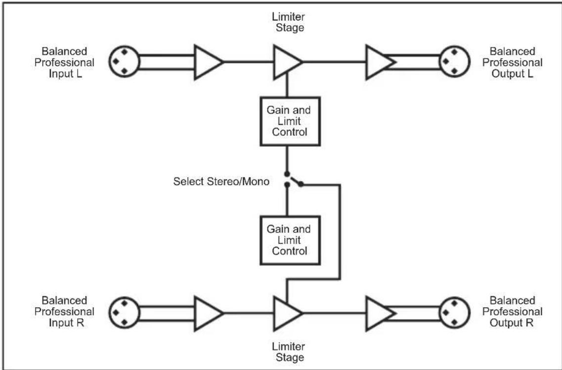
flowchart
graph TD
    A["Balanced Professional Input L"] --> B["Gain and Limit Control"]
    C["Balanced Professional Input R"] --> D["Limiter Stage"]
    B --> E["Select Stereo/Mono"]
    D --> F["Limiter Stage"]
    E --> G["Gain and Limit Control"]
    F --> H["Gain and Limit Control"]
    G --> I["Output L"]
    H --> J["Output R"]
Fig 8-2: RB-SL2 Block Diagram.
Rear Panel Connections and Operation

natural_image
Red industrial machine with control panel and buttons (no visible text or symbols)Fig 8-3: RB-SL2 Rear Panel.
Outputs
The XLR 3 pin plug connectors are electronically balanced and can be wired unbalanced to accept an output from domestic equipment. They have the following connections:
Pin 1: Screen
Pin 2: Phase
Pin 3: Non-phase
Inputs
The XLR 3 pin sockets are electronically balanced, and can be wired unbalanced to accept an output from domestic equipment. They have the following connections:
Pin 1: Screen
Pin 2: Phase
Pin 3: Non-phase
Gain Control
Each channel has an input gain (GAIN) and a threshold level control (LIMIT LEVEL). Setting the limit level to maximum (fully anti-clockwise) enables the input through to output to be normalised using the input gain potentiometers. Once the unit is acting as a buffer with gain/attenuation, the limit level can be set, with the recovery adjusted for the application. Limiting is indicated by the power LED on the front panel flashing.
Mode Switch
This switch changes the unit from dual mono to stereo mode. In stereo mode, only the pre-sets for channel 1 (left) are active and they are applied to both channels. Stereo limiting operates by limiting both left and right outputs if either left or right input needs to be limited. Dual mono limiting operates by limiting left and right signals individually – you can use the RB-SL2 as two separate mono limiters.
8
MICROPHONE AMPLIFIERS & LIMITERS

Technical Specifications RB-SL2
Audio Specifications
Maximum Input Level: +28dBu
Maximum Output Level: +28dBu
Input Impedance: >20kΩ bridging
Output Impedance: <50Ω
Input Gain: Adjustable -8dBu to +18dBu gain
Limit Threshold: Adjustable -8dBu to +28dBu
Frequency Response: 20Hz to 20kHz ±0.1dB (600Ω load, ref 1kHz)
Noise: -100dB unity gain, ref +8dBu
Distortion: 0.01% THD @ 1kHz ref +8dBu output, threshold set at +10dBu
Common Mode Rejection: >66dB typically
Connections
Inputs: 2 x XLR 3 pin female (Balanced, can be unbalanced)
Outputs: 2 x XLR 3 pin male (Balanced, can be unbalanced)
Mains Input: Filtered IEC, 110V-120V, or 220-240V switchable, fused, 6W maximum
Equipment Type
RB-SL2:
Twin mono, or stereo, limiter


Physical Specifications
Dimensions (Raw): 28cm (W) x 10.8cm (D) x 4.2cm (H) (1U)
Dimensions (Boxed): 36cm (W) x 20.5cm (D) x 6cm (H)
Weight: Nett: 1.0kg Gross: 1.45kg
9 RB-SM1 Single & RB-SM2 Dual Stereo To Mono Converter
Introduction

Fig 9-1: RB-SM1 & RB-SM2 Front Panel.
The RB-SM1 consists of an independent converter that will produce a fully buffered and balanced mono line output from a stereo input. The RB-SM2 consists of two independent converters and will produce two fully buffered and balanced mono line outputs from two stereo inputs.
All connections are on the rear panel. The XLR-3 inputs are electronically balanced with an impedance of 20kΩ bridging. These can be wired unbalanced to accept an output from domestic equipment.
The XLR-3 line output's are electronically balanced with an output impedance of < 50 . The output's can be wired unbalanced by grounding the non-phase signal, allowing you to feed both balanced and unbalanced equipment.
Output gain adjustment using a pre-set potentiometer for both converters allows a normalised mono output from domestic stereo equipment. The potentiometer is accessible through the rear panel. An LED power indicator on the front panel displays the power supply connection.
The rest of this manual will refer to the SM1 unless stated otherwise.
System Block Diagram

flowchart
graph LR
    A["Left"] --> B["Summing Amplifier"]
    C["Right"] --> B
    B --> D["Professional Balanced Mono Output"]
    style A fill:#fff,stroke:#000
    style C fill:#fff,stroke:#000
    style B fill:#fff,stroke:#000
    style D fill:#fff,stroke:#000
    note right of B: "Summing Amplifier"
    note right of D: "Professional Balanced Mono Output"
    note right of B: "Gain"
    note right of D: "Professional Balanced Stereo Input"
Fig 9-2: RB-SM1 & RB-SM2 Block Diagram Single Channel.

natural_image
Red industrial machine with control panel and buttons (no visible text or symbols)
Rear Panel Connections and Operation

Fig 9-3: RB-SM1 Rear Panel..
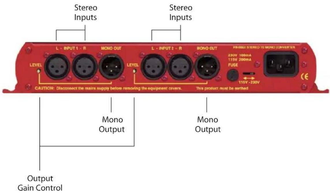
Fig 9-4: RB-SM2 Rear Panel.
Stereo Inputs 1 (& 2)
The input's are a stereo pair consisting of two XLR 3 pin sockets electronically balanced with an impedance of 20k bridging. They can be wired unbalanced to accept an output from domestic equipment. They have the following connections:
Pin 1: Screen
Pin 2: Phase
Pin 3: Non-phase
Mono Output 1 (& 2)
The XLR 3 pin mono output connectors are electronically balanced with an output impedance of < 50 . They can be wired unbalanced by grounding the non-phase signal, enabling you to feed both balanced and unbalanced equipment. The output has the following connections:
Pin 1: Screen
Pin 2: Phase
Pin 3: Non-phase
Output Gain
Output gain adjustment using a pre-set potentiometer for the converters allows a normalised mono output from domestic stereo equipment. The potentiometers are accessible through the rear panel and provide a gain range of 8dB loss to 18dB gain.

natural_image
Close-up of a red electronic device with buttons and a white cable, no visible text or symbols
Technical Specifications RB-SM1 & RB-SM2
Audio Specifications
Maximum Input Level: +28dBu
Maximum Output Level: +28dBu
Input Impedance: >20kΩ balanced bridging
Output Impedance: <50Ω balanced
Frequency Response: 20Hz to 20kHz ±0.1dB (600Ω load, ref 1kHz)
Gain Range: Adjust 8dB loss to 18dB gain, ref 0dB input on L and R
Common Mode Rejection: >66dB typically
Distortion: 0.01% THD @ 1kHz, ref +8dBu output
Noise: -100dB unity gain, ref +8dBu output
Connections
Inputs: 2 (4 on RB-SM2) x XLR 3 pin female (Balanced, can be unbalanced)
Output: 1 (2 on RB-SM2) x XLR 3 pin male (Balanced, can be unbalanced)
Mains Input:
Filtered IEC, 110V-120V, or 220-240V switchable, fused, 6W maximum
Equipment Type
RB-SM1:
Dual stereo to mono converter
RB-SM2:
Single stereo to mono converter


Physical Specifications
| Dimensions (Raw): | 28cm (W) x 10.8cm (D) x 4.2cm (H) (1U) |
| Dimensions (Boxed): | 36cm (W) x 20.5cm (D) x 6cm (H) |
| Weight RB-SM1: | Nett: 1.00kg Gross: 1.45kg |
| Weight RB-SM2: | Nett: 1.05kg Gross: 1.50kg |
10 RB-LC3 3 Way Light/Power Controller
Introduction

Fig 10-1: RB-LC3 Front Panel.
The RB-LC3 is a triple output switching unit for controlling external mains indicators, primarily studio status lights for broadcasting applications, such as On-Air, Mic-Live and Rehearsal/Live lights. Each output can be individually controlled by one of three remote inputs (pulled high, or low), by a telephony input (when ringing, or off-hook or both), or a combination of two inputs (to control two outputs, e.g. for Rehearsal/Live situations). The type of control is set using a 12 way DIP switch (4 switches for each output allowing 16 different settings).
All connections are on the rear panel. The three IEC outputs are controlled by zero-cross point drivers. When an output is activated, the A.C. voltage level at that output will be equal to the mains input voltage used to power the unit.
External control of the switched mains outputs is via the 15 way D-type plug connector.
The telephone Line input and Handset output are via two RJ11-4 type connectors. The telephone connections are wired pin to pin from Line to Handset except when the remote Ring Mute control input is asserted. In this case the ring signal to the Handset is muted. The status of the telephone Line is continually monitored so that Handset ringing and off-hook conditions can be indicated.
A pre-set potentiometer on the rear panel controls the flash rate of the output when the appropriate mode is selected. Neon indicators on each power socket show the status of the mains output.
An LED power indicator on the front panel displays the incoming power supply connection

natural_image
Red industrial machine with control panel and indicator lights (no visible text or symbols)10
GENERAL INTERFACES
SONIFEX

natural_image
Red and orange abstract background with no visible text or symbolsGENERAL INTERFACES - RB-LC3
System Block Diagram
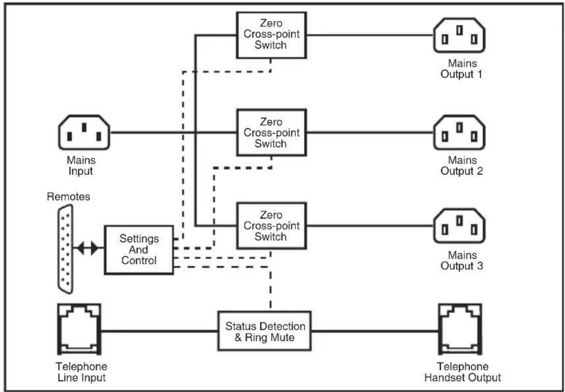
flowchart
graph TD
    A["Mains Input"] --> B["Settings And Control"]
    C["Remotes"] --> B
    B --> D["Status Detection & Ring Mute"]
    D --> E["Telephone Handset Output"]
    F["Zero Cross-point Switch"] --> G["Mains Output 1"]
    H["Zero Cross-point Switch"] --> I["Mains Output 2"]
    J["Zero Cross-point Switch"] --> K["Mains Output 3"]
    L["Telephone Line Input"] --> D
    style A fill:#f9f,stroke:#333
    style C fill:#f9f,stroke:#333
    style F fill:#ccf,stroke:#333
    style H fill:#ccf,stroke:#333
    style J fill:#ccf,stroke:#333
    style L fill:#ccf,stroke:#333
Fig 10-2: RB-LC3 Block Diagram.
Rear Panel Connections and Operation
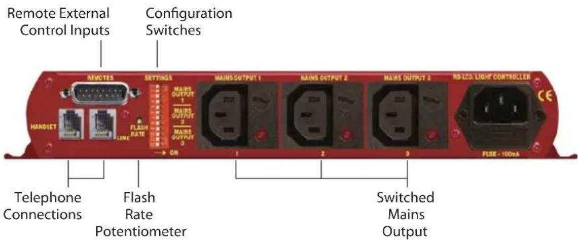
Fig 10-3: RB-LC3 Rear Panel
Switched Mains Outputs
The 3 off IEC connectors provide the switched mains outputs. Each output is rated at 1A and is individually fused. A neon indicator shows when the output is live. The outputs are driven by zero cross-point drivers. When an output is activated, the A.C. voltage level at that output will be equal to the mains input voltage used to power the unit.
Telephone Connections
The telephone connections are wired pin to pin from Line to Handset except when the Ring Mute control input is asserted. In this case the ring signal to the Handset is muted. The status of the telephone Line is continually monitored so that Handset ringing and off-hook conditions can be indicated.
Remote External Control Inputs
The 15 way D-type connector provides the control inputs that switch the three mains outputs and control the telephone handset ring mute. All inputs have both active high (+5V to +30V) and active low (0V) control. An output-on or "Tally" indication for each output is also provided on this connector in the form of three open-collector driven outputs capable of sinking 20mA each. The connections are as follows:
Pin 1: Remote 1 (Active High)
Pin 2: Remote 1 (Active Low)
Pin 3: Remote 2 (Active High)
Pin 4: Remote 2 (Active Low)
Pin 5: Remote 3 (Active High)
Pin 6: Remote 3 (Active Low)
Pin 7: Ring Mute (Active High)
Pin 8: Ring Mute (Active Low)
Pin 9: Output 1 Tally (Open Collector)
Pin 10: Output 2 Tally (Open Collector)
Pin 11: Output 3 Tally (Open Collector)
Pin 12: No Connection
Pin 13: No Connection
Pin 14: 0V
Pin 15: 0V

natural_image
Close-up of a red electronic device with visible components and no readable text or symbols10
GENERAL INTERFACES
SONIFEX

GENERAL INTERFACES - RB-LC3
Configuration Switches
The configuration switches are used to set the flash mode for each output separately. The selections allow the outputs to be controlled by a remote input, a telephone call, or a combination of remote inputs, say, for example to control 2 lights such as "Rehearsal" and "Live", using Settings 10-13. The available settings for each output are detailed below:
| Setting No | Sw1 Sw2 Sw3 Sw4 Description | ||||
| 1 Off Off Off Off | Flash Output 1 when telephone rings. Output 1 On when telephone is off-hook | ||||
| 2 On Off Off Off | Output 1 On when telephone is off-hook | ||||
| 3 Off On Off Off | Flash Output 1 when telephone rings | ||||
| 4 On On Off Off | Output 1 | On when | Remote 1 | asserted | |
| 5 Off Off On Off | Output 1 | On when | Remote 2 | asserted | |
| 6 On Off On Off | Output 1 | On when | Remote 3 | asserted | |
| 7 Off On On Off | Flash Output 1 when Remote 1 asserted | ||||
| 8 On On On Off | Flash Output 1 when Remote 2 asserted | ||||
| 9 Off Off Off On | Flash Output 1 when Remote 3 asserted | ||||
| 10 On Off Off On | Output 1 On when Remote 1 or Remote 2 asserted | ||||
| 11 Off On Off On | Output 1 On when Remote 1 asserted and Remote 2 not asserted | ||||
| 12 On On Off On | Output 1 On when Remote 1 not asserted and Remote 2 asserted | ||||
| 13 Off Off On On | Output 1 On when Remote 1 asserted and Remote 2 asserted | ||||
| 14 On Off On On | Reserved | for future | assignment | ||
| 15 Off On On On | Reserved | for future | assignment | ||
| 16 On On On On | Reserved | for future | assignment | ||
Fig 10-4: Output 1 Configuration Setting.
| Setting No | Sw5 | Sw6 | Sw7 | Sw8 | Description | |
| 1 Off | Off | Off | Off | Flash Output 2 when telephone rings. Output 2 On when telephone is off-hook | ||
| 2 On | Off | Off | Off | Output 2 On when telephone is off-hook | ||
| 3 Off | On | Off | Off | Flash Out | put 2 when telephone rings | |
| 4 On | On | Off | Off | Output 2 | On when Remote 1 | asserted |
| 5 Off | Off | On | Off | Output 2 | On when Remote 2 | asserted |
| 6 On | Off | On | Off | Output 2 | On when Remote 3 | asserted |
| 7 Off | On | On | Off | Flash Output 2 when Remote 1 asserted | ||
| 8 On | On | On | Off | Flash Output 2 when Remote 2 asserted | ||
| 9 Off | Off | Off | On | Flash Output 2 when Remote 3 asserted | ||
| 10 On | Off | Off | On | Output 2 On when Remote 1 or Remote 2 asserted | ||
| 11 Off | On | Off | On | Output 2 On when Remote 1 asserted and Remote 2 not asserted | ||
| 12 On | On | Off | On | Output 2 On when Remote 1 not asserted and Remote 2 asserted | ||
| 13 Off | Off | On | On | Output 2 On when Remote 1 asserted and Remote 2 asserted | ||
| 14 On | Off | On | On | Reserved | for future assignment | |
| 15 Off | On | On | On | Reserved | for future assignment | |
| 16 On | On | On | On | Reserved | for future assignment | |
Fig 10-5: Output 2 Configuration Settings.

natural_image
Close-up of a red electronic device with buttons and display (no visible text or symbols)GENERAL INTERFACES - RB-LC3
10 GENERAL INTERFACES

natural_image
Close-up of a red electronic device with control knobs and buttons (no visible text or symbols)GENERAL INTERFACES - RB-LC3
| Setting No | Sw9 | Sw10 | Sw11 | Sw12 | Description | |
| 1 Off | Off | Off | Off | Flash Output 3 when telephone rings. Output 3 On when telephone is off-hook | ||
| 2 On | Off | Off | Off | Output 3 On when telephone is off-hook | ||
| 3 Off | On | Off | Off | Flash Out | put 3 when telephone rings | |
| 4 On | On | Off | Off | Output 3 | On when Remote 1 | asserted |
| 5 Off | Off | On | Off | Output 3 | On when Remote 2 | asserted |
| 6 On | Off | On | Off | Output 3 | On when Remote 3 | asserted |
| 7 Off | On | On | Off | Flash Output 3 when Remote 1 asserted | ||
| 8 On | On | On | Off | Flash Output 3 when Remote 2 asserted | ||
| 9 Off | Off | Off | On | Flash Output 3 when Remote 3 asserted | ||
| 10 On | Off | Off | On | Output 3 On when Remote 1 or Remote 2 asserted | ||
| 11 Off | On | Off | On | Output 3 On when Remote 1 asserted and Remote 2 not asserted | ||
| 12 On | On | Off | On | Output 3 On when Remote 1 not asserted and Remote 2 asserted | ||
| 13 Off | Off | On | On | Output 3 On when Remote 1 asserted and Remote 2 asserted | ||
| 14 On | Off | On | On | Reserved | for future assignment | |
| 15 Off | On | On | On | Reserved | for future assignment | |
| 16 On | On | On | On | Reserved | for future assignment | |
Fig 10-6: Output 3 Configuration Settings.
Flash Rate Preset Potentiometer
This preset potentiometer sets the rate at which the mains output is switched on/off when one of the Flash Output settings is selected. The range of adjustment is from 0.5 seconds to 2 seconds.
Technical Specifications RB-LC3
Connections
Mains Input: Non-filtered IEC, 110V-240V auto-adjusting, fused, 6W maximum
Mains Outputs: 3 x Non-filtered IEC plugs, 1A fused
Telephone: 2 x RJ11-4 sockets
Control Inputs & Outputs: 15 way D-type plug
Inputs: 0V–5V DC
Outputs: Open Collector 20mA sink capability
Equipment Type
RB-LC3: 3 way light/power controller


Physical Specifications
Dimensions (Raw): 28cm (W) x 10.8cm (D) x 4.2cm (H) (1U)
Dimensions (Boxed): 36cm (W) x 20.5cm (D) x 6cm (H)
Weight: Nett: 1.00kg Gross: 1.45kg

natural_image
Red and orange electronic device with buttons and display screens (no visible text or symbols)11
GENERAL INTERFACES
BONIFEX

Fig 11-1: RB-MM1 Front Panel.
Whenever programming originates from outside of the studio, or if listeners/viewers are calling up a phone-in using telephone hybrids or codecs, mix-minus feeds are required. Most telephone lines incur delays which prohibit off-air monitoring, because the caller, or remote talent, would hear their own voice in delay which is very disconcerting. The solution is to feed a mix back to the caller minus his or her own voice. Some mixing desks do not have a dedicated telco channel to generate a clean-feed, or mix minus, so the RB-MM1 can be used.
The RB-MM1 is a unit for generating a suitable mix to send to a telephone hybrid or codec. A stereo output is taken from a mixer, together with a post fader output from the mono telephone fader on the mixer. The caller audio is removed from the station output so that it can be sent to the telephone line via the hybrid.
Analogue audio inputs and outputs are via Neutrik XLR connectors. The output level to the TBU can be adjusted using a rear panel pre-set potentiometer. To control the cancellation null, 2 multi-turn potentiometers are provided, one for the LF null and the other for the full-band null. Additionally, a band pass filter can be switched in and out, via a rear panel switch, to condition the signal for the telephone hybrid. To use the RB-MM1 unit with full-band ISDN codecs, the band pass filter can be switched out. For stereo codecs, or conference calls, multiple RB-MM1 units can be used.
A red LED indicates when power to the RB-MM1 is on.
System Block Diagram

flowchart
graph LR
    A["Balanced Stereo Input From Mixer"] --> B["Input L"]
    C["Balanced Mono Input From Telephone Fader"] --> D["Input R"]
    B --> E["Σ"]
    D --> E
    E --> F["Filter Switch"]
    F --> G["Output Level"]
    G --> H["Bandpass Filter"]
    H --> I["Output"]
    I --> J["Balanced Output To TBU"]
Fig 11-2: RB-MM1 System Block Diagram.
Front Panel Indicator
The LED on the front panel is normally red to indicate that power is present on the unit.
Rear Panel Connections and Operation
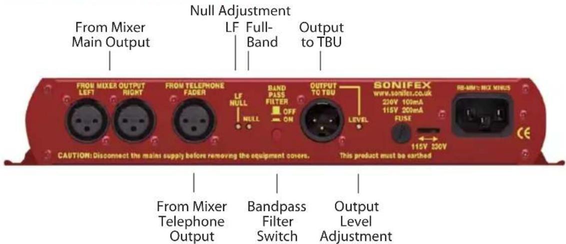
Fig 11-3: RB-MM1 Rear Panel.
Stereo Inputs From Mixer Main Output
These inputs should contain the main mixer output which will be a feed of the programme plus the audio that you want to remove by the mix-minus unit. Ideally, the input should be presented at 0dB. The XLR 3 pin sockets used for the left and right channel inputs are electronically balanced and have an impedance of greater than 10kΩ bridging. Each XLR has the following connections:
Pin 1: Screen.
Pin 2: Phase.
Pin 3: Non-phase.
Input From Mixer Telephone Fader
This mono input should contain the audio that needs to be removed by the RB-MM1, usually from the telephone/telco fader of a mixing console. Ideally, the input should be presented at 0dB. The XLR 3 pin socket used for the mono channel input is electronically balanced and has an impedance of greater than 20k bridging. The XLR has the following connections:
Pin 1: Screen.
Pin 2: Phase.
Pin 3: Non-phase.
Output Null Adjustments (LF and Full-Band)
The 2 x null preset potentiometers are used to adjust the null between the input from the telephone fader and the main stereo input. The telephone input is made anti-phase and used to cancel out that signal in the main stereo signal. So, the nulls adjust the level of anti-phase signal required to achieve the best mix-minus null.

natural_image
Red and orange abstract background with no visible text, numbers, or symbols11
GENERAL INTERFACES

natural_image
Red industrial machine with control panel and conveyor belt (no visible text or symbols)Band Pass Filter Switch
The band pass filter, when in the ON position, is used to limit the audio bandwidth of the output to the TBU between 200Hz and 4kHz. When using the RB-MM1 in full bandwidth equipment, e.g. for ISDN audio codecs, set this switch to the OFF position.
Output to Telephone Balance Unit (TBU)
The mono XLR 3 pin output plug connector is electronically balanced with an output impedance of less than 50Ω. It has the following connections:
Pin 1: Screen.
Pin 2: Phase.
Pin 3: Non-phase.
Output Level Adjustment
The TBU output gain can be adjusted from -15dB to +12dB, ref 0dBu by using the LEVEL preset potentiometer.
Operation of the RB-MM1
Before you receive your RB-MM1, it is calibrated at Sonifex by using two signals of equivalent amplitude and frequency. In some cases it may require recalibrating for use on a mixer to match the properties of that mixer. In order to do this make the following connections:
- Mixer left output to the RB-MM1 left input.
- Mixer right output to the RB-MM1 right input.
- Mixer post fade output from the relevant input channel (usually telco) to the RB-MM1 telephone fader input.
Then apply a signal to the input channel and raise the fader to its maximum level. To get the best results connect a level meter to the "Output to TBU" connector. Alternatively monitor the output acoustically and tune by ear.
Then adjust the NULL potentiometer until the output is as low as possible, if there is still some low frequency output adjust the LF NULL as well. The null available on this product is >40dB at 1kHz.
Technical Specification RB-MM1
Audio Specification For RB-MM1
Maximum Input Level: +28dBu
Input Impedance: >20kΩ
Maximum Output Level: +28dBu
Output Impedance: <50Ω
Output Gain Range: Adjustable -15dB to +12dB, ref 0dBu gain via a multi-turn pot
Common Mode Rejection: >60dB
Band Pass Filter Range: 200Hz to 4kHz, 12dB/octave
LF Null Adjustment: Better than 40dB at 100Hz
Mix-Minus Null: Better than 40dB at 1kHz
Frequency Response: 20Hz - 22kHz ± 0.1dB
Distortion: 0.01% THD @ 1kHz, ref +8dBu output (C-Message weighted)
Noise: -90dBu unity gain, ref +6dBu
Connections
Analogue Inputs From 2 x XLR 3 pin female (balanced) (L & R)
Mixer Output:
Analogue Input From 1 x XLR 3 pin female (balanced) (L & R)
Telephone Fader:
Analogue Output To TBU: 1 x XLR 3 pin male (balanced) (L & R)
Mains Input: Filtered IEC, switchable 110-120V, or 220-240V, fused, 6W max.
Equipment Type
RB-MM1:
Mix-minus generator


11 GENERAL INTERFACES

natural_image
Red and yellow abstract image with no discernible text, symbols, or identifiable objects.Physical Specification
Dimensions (Raw): 28cm (W) x 10.8cm (D) x 4.3cm (H)
Dimensions (Boxed): 36cm (W) x 20.5cm (D) x 6cm (H)
Weight: Nett: 1.1kg Gross: 1.5kg


natural_image
Red and orange abstract background with no visible text, numbers, or symbolsNOTES
SONIFEX
www.sonifex.co.uk
t:+44 (0)1933 650 700
f:+44 (0)1933 650 726
sales@son i fex.co.uk


- Redbox User Handbook No3
- Warranty i
- Safety Information iii
- RB-SS10 10 Way Stereo Analogue Source Selector/Mixer 1
- RB-DSS10 10 Way Stereo Digital Source Selector 11
- RB-PMX4 10 Input, 4 Output Analogue Preset Mixer 21
- RB-SSML1 Mic/Line Source Selector with Compressor Limiter 25
- RB-MA1 Single & RB-MA2 Dual Microphone Amplifiers 31
- RB-DMA2 Dual Digital Microphone Amplifier 35
- RB-ML2 Stereo Microphone & Line Level Limiter 44
- RB-SL2 Twin Mono, or Stereo, Limiter 50
- RB-SM1 Single & RB-SM2 Dual Stereo To Mono Converter 53
- RB-LC3 3 Way Light/Power Controller 57
- RB-MM1 Mix Minus Generator 64
- Figures
- Warranty
- Warranty and Liability - important the purchaser is advised to read this clause
- Unpacking the Redbox
- Returning the Warranty Card
- Safety Information
- Safety of Mains Operated Equipment
- Voltage Setting Checks
- Fuse Rating
- Voltage Fuse
- Power Cable and Connection
- Wire Colour Connection
- Ordering the Correct Mains Lead
- Installation Information
- Atmosphere
- Electromagnetic Radiation
- Fitting Redboxes
- WEEE & RoHS Directives - Sonifex Statement
- RB-SS10 10 Way Stereo Analogue Source Selector/Mixer
- Introduction
- 1
- MIXER & SOURCE SELECTORS
- SONIFEX
- Front Panel Indicators & Controls
- Illuminated Push Buttons
- Front Panel Gain Controls
- Headphone Output
- Volume Control
- Additional Modes
- Alternate Mode
- Latched Mode
- Protected Alternate Mode
- Configuring the Additional Modes
- Rear Panel Connections and Operation
- Inputs
- Outputs
- Altering the Master Output Level
- RB-SS10 Additional Audio Input Connectors
- RB-SS10 Remote Start I/O
- Remote Select/Switch Inputs
- Status Outputs
- Technical Specifications RB-SS10
- Audio Specifications
- Connections
- Equipment Type
- Physical Specifications
- RB-DSS10 10 Way Stereo Digital Source Selector
- 2
- Power Indicator
- RB-DSS10 Inputs
- AES/EBU Inputs
- RB-DSS10 Outputs
- AES/EBU Outputs
- Digital Audio Inputs & S/PDIF Output
- Remote Start I/O
- Technical Specifications RB-DSS10
- Audio Connections
- Other Connections
- RB-PMX4 10 Input, 4 Output Analogue Preset Mixer
- Inputs 1-10
- Outputs 1-4
- Switch Banks
- Input Gain Controls
- Technical Specifications RB-PMX4
- RB-SSML1 Mic/Line Source Selector with Compressor Limiter
- 4
- Stereo Monitor Inputs
- Stereo Monitor Pad & Volume Control
- Mic Input
- Mic Input Gain
- Using Phantom Powered Microphones
- Using the LF Filter
- Compression Active on Mic Input Only
- Peak Hold Disabled on LED Meter
- Stereo Line Input
- Stereo Input Gain Pad
- Stereo Line Output
- Stereo Output Gain Pad
- Mic & Line Volume Controls
- Mic/Line Select Switch
- Bypass Button
- Applying Compression
- LED Metering
- Headphone Outputs
- Technical Specifications RB-SSML1
- Audio Specifications (Bypass Mode)
- RB-MA1 Single & RB-MA2 Dual Microphone Amplifiers
- System Block Diagram
- 5
- MICROPHONE AMPLIFIERS & LIMITERS
- Mic Inputs
- Input Gain
- Output
- Technical Specifications RB-MA1 & RB-MA2
- RB-DMA2 Dual Digital Microphone Amplifier
- 6
- Sync & Power Indicator
- Input Level Adjustment
- Disabling the Fine Gain Control Knob
- Input Level Indicators
- RB-DMA2 Inputs
- RB-DMA2 Outputs
- AES/EBU Output
- Analogue Line Outputs
- Rear Panel Controls
- Status Select Switches
- Output Routing
- Note: This does not affect the routing of the analogue outputs.
- Phantom Power & LF Filter
- Digital Sync & Output Select Buttons
- Frequency and Sync Mode Rotary Switch
- Test/Calibration Mode
- Technical Specifications RB-DMA2
- Audio Specification
- Operational Controls & Indicators
- 7
- RB-ML2 Stereo Microphone & Line Level Limiter
- Mic / Line Inputs
- Mic / Line Outputs
- Mic / Line Output Gain
- Level Limiting
- Mode Select Switch
- Technical Specifications RB-ML2
- 8
- Gain Control
- Mode Switch
- Technical Specifications RB-SL2
- RB-SM1 Single & RB-SM2 Dual Stereo To Mono Converter
- Stereo Inputs 1 (& 2)
- Mono Output 1 (& 2)
- Output Gain
- Technical Specifications RB-SM1 & RB-SM2
- RB-LC3 3 Way Light/Power Controller
- 10
- GENERAL INTERFACES
- Switched Mains Outputs
- Telephone Connections
- Remote External Control Inputs
- Configuration Switches
- GENERAL INTERFACES
- Flash Rate Preset Potentiometer
- Technical Specifications RB-LC3
- 11
- Front Panel Indicator
- Stereo Inputs From Mixer Main Output
- Input From Mixer Telephone Fader
- Output Null Adjustments (LF and Full-Band)
- Band Pass Filter Switch
- Output to Telephone Balance Unit (TBU)
- Output Level Adjustment
- Operation of the RB-MM1
- Technical Specification RB-MM1
- Audio Specification For RB-MM1
- GENERAL INTERFACES
- Physical Specification
Brand : Sonifex
Model : Redbox RB-MA1
Category : Professional audio equipment