
MB200 - Speaker Stand ELECTRO-VOICE - Free user manual and instructions
Find the device manual for free MB200 ELECTRO-VOICE in PDF.


| Product Type | Speaker Stand |
| Brand | Electro-Voice |
| Model | MB200 |
| Material | Steel |
| Height Range | 1.2 m to 2.0 m (approx) |
| Maximum Load Capacity | 50 kg (110 lbs) |
| Base Diameter | 1.2 m (approx) |
| Weight | 5 kg (11 lbs) |
| Color | Black |
| Foldable | Yes |
| Pole Adapter | M20 threaded, 35 mm diameter |
| Locking Mechanism | Spring-loaded pins |
| Feet | Rubber, non-slip |
| Carry Bag Included | Optional (sold separately) |
| Warranty | 2 years |
| Cleaning | Wipe with a damp cloth, avoid solvents |
| Maintenance | Check hardware tightness periodically |
| Safety Warning | Do not exceed maximum load; ensure stand is fully locked before use |
| Spare Parts Availability | Contact Electro-Voice dealer or service center |
| Reparability | Yes, by qualified technician |
Frequently Asked Questions - MB200 ELECTRO-VOICE
User questions about MB200 ELECTRO-VOICE
0 question about this device. Answer the ones you know or ask your own.
Ask a new question about this device
Download the instructions for your Speaker Stand in PDF format for free! Find your manual MB200 - ELECTRO-VOICE and take your electronic device back in hand. On this page are published all the documents necessary for the use of your device. MB200 by ELECTRO-VOICE.
USER MANUAL MB200 ELECTRO-VOICE
natural_image
Technical line drawing of a multi-tiered mechanical housing or enclosure with mounting holes and internal compartments (no text or symbols)Mb200
And Mb200W Installation Kit
- Mounting kit for System ™ 200 speakers
- May be used in conjunction with OmniMount® Series 100 support system ^1
- Versatile design allows the speaker to be aimed at any angle from wall or ceiling
- Provides a rigid frame for flying one or two speakers
- Creates arrays of two to six speakers when used with the M_b 300 Horizontal Array Kit
Description
The M_b 200 installation kit consists of a U-bracket, two M8 x 1.25 hex-head bolts, four lock washers, two friction pads, and two 38 -24 hex-head bolts (see Chart 1). The kit is designed to accommodate the System 200 ^TM installation in a variety of ways.
Wall or Ceiling Mounting:
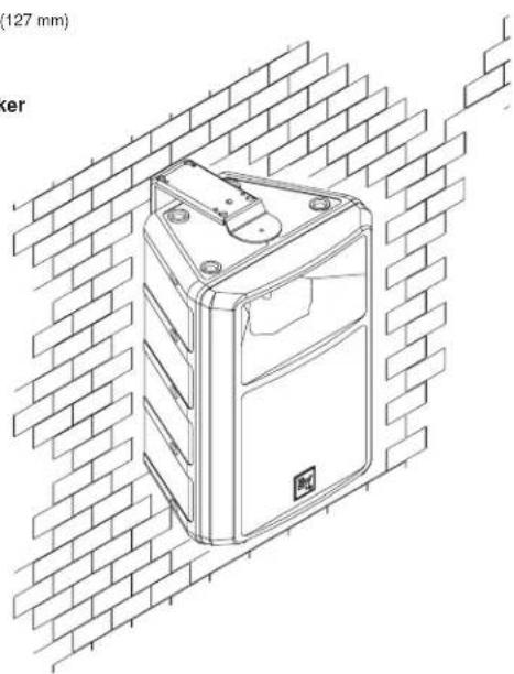
The robust design of the M_b 200 installation bracket allows the System 200 ^TM speakers to be mounted in almost any position to obtain the desired sound coverage (see Figure 3).
Flying Installations
The M_b 200 bracket “captures” the speaker
in a rigid frame which has structurally sound locations for attaching rigging hardware. These attachment points are four 12.7-mm ( ^1/2 -in.) diameter holes located on the ends of the bracket. A ^3/8 -in. “quick link” (or similar hardware) can be readily connected to each attachment point.
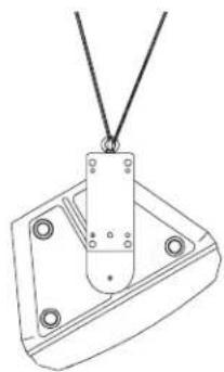
System 200 ^TM speakers can be flown individually in either a horizontal or vertical position, or two speakers can be flown together in a vertical position (see Figures 4 and 5).
System 200 ^TM Horizontal Arrays
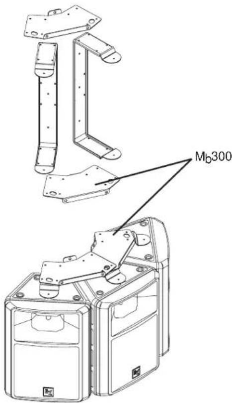
Arrays of two to six speakers are securely supported in a frame comprised of M_b200 and M_b300 brackets. To create a horizontal array, two M_b200 brackets are simply locked into the correct alignment position using the brackets from the M_b300 Horizontal Array
Kit (see Figure 6). The array is extended by using one additional M_b 200 bracket and one M_b 300 kit for each additional speaker. To complete the circle for a six speaker array, one additional M_b 300 kit is required. Please refer to Chart 2 to select the exact number of each kit needed, based on desired array size. (Note: refer to M_b 300 Horizontal Array Kit engineering data sheet for detailed instructions on System 200^TM horizontal array construction using M_b 200 Installation and M_b 300 Horizontal Array Kits.)
CHART 1: M_b200 Installation Kit Parts List
| Item Description Quantity Part Number | ||
| A Bracket 1 71914 | ||
| B M8 x 1.25 hex head bolt 2 63310 | ||
| C 5/16 split ring lock washer | 2 38144 | |
| D 3/8-24 hex head bolt | 2 63311 | |
| E 3/8 split ring lock washer | 2 38834 | |
| F Friction washer | 2 38829 |
CHART 2: Kit Requirements for System 200™ Horizontal Array Construction
| # of Enclosures # of Kits in Array: M | Req'd200 Mb | 300 |
| 2 | 2 | 1 |
| 3 | 3 | 2 |
| 4 | 4 | 3 |
| 5 | 5 | 4 |
| 6 (complete circle) 6 6 |
Wall Mounting Instructions
CAUTION: Due to the weight of System 200 ^™ speakers, it is imperative that the M _b 200 bracket be properly secured to the wall or ceiling. The choice of fastener (not provided with this kit) will be determined by the material and construction of the mounting surface.
- Refer to Figure 1 for the following steps.
- Remove the paper backing from one of the friction pads (F) and, making sure the holes are aligned, attach to the U-bracket (A) as shown. Attach the second friction pad in a similar manner.
-
Attach the U-bracket to the wall or ceiling using fasteners (not supplied) that are suitable for the construction material.
-
Remove the hole plugs from the ends of the System 200 ^TM speaker by gently prying with a small screwdriver.
-
Place one of the smaller lock washers (C) on each of the two M8 bolts (B).
-
Place the speaker into the U-bracket and finger tighten the M8 bolts.
-
Rotate the speaker so that the input panel is accessible and attach the wires to the input panel.
-
Position the speaker for the desired coverage and gently tighten the M8 bolts until the speaker will no longer rotate. DO NOT OVERTIGHTEN.
Note: The ^3/_8 24 bolts (D) are used to lock the speaker parallel to the bracket and prevent it from being rotated. This is needed when arraying the speaker for proper alignment and when flying in the vertical position.
Flying Instructions
NOTE: A maximum of two speakers can be suspended together vertically using the M_b 200 installation bracket.
- Refer to Figure 1 for the following steps.
- Remove the paper backing from one of the friction pads (F) and, making sure the holes are aligned, attach to the U-bracket (A) as shown. Attach the second friction pad in a similar manner.
- Remove the hole plugs from the ends of
M_b 200 SPECIFICATION GRAPHICS
FIGURE 1 — Attaching M _200 Bracket
to System 200™ Speaker (exploded view)
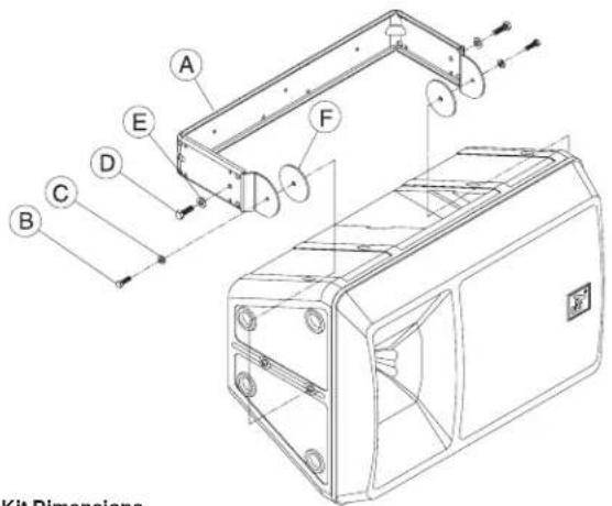
FIGURE 2 — Mb200 Installation Kit Dimensions
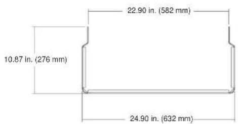
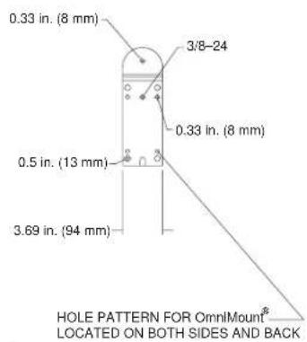
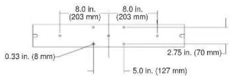
FIGURE 3 — Wall-Mounting a System 200™ Speaker Using the Mb200 Installation Kit
natural_image
Line drawing of a mechanical device mounted on a brick wall, no text or symbols present- OmniMount is a registered trademark of OmniMount Systems, Inc.
Mb200/Mb200W Installation Kit
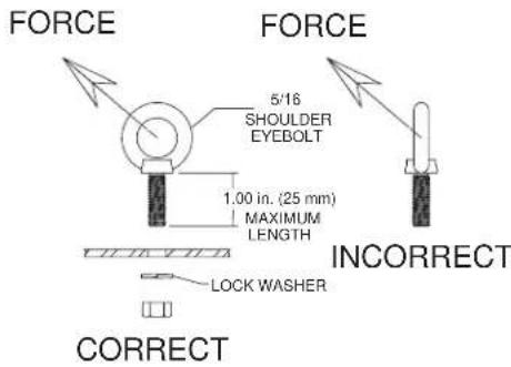
FIGURE 4A — Correct and Incorrect Eyebolt Orientation
FIGURE 4B — Horizontal Suspension of a System 200™ Speaker Using M _b 200 Installation Kit (side view)
FIGURE 4C — Horizontal Suspension of a System 200™ Speaker Using Mb200 Installation Kit (isometric view)
natural_image
Technical line drawing of a mechanical clamp or bracket with mounting holes and a suspended rod (no text or symbols)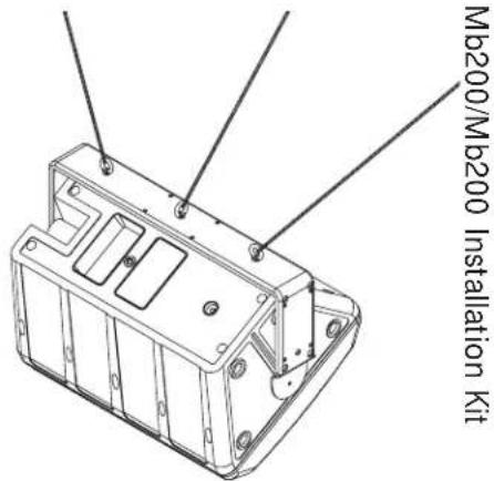
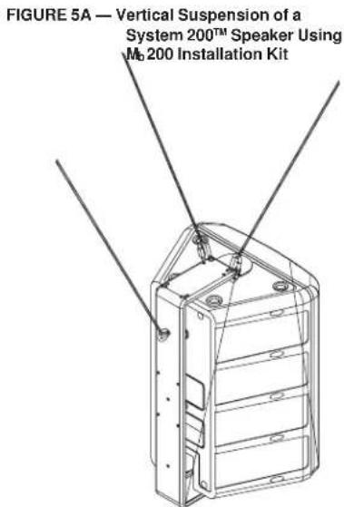
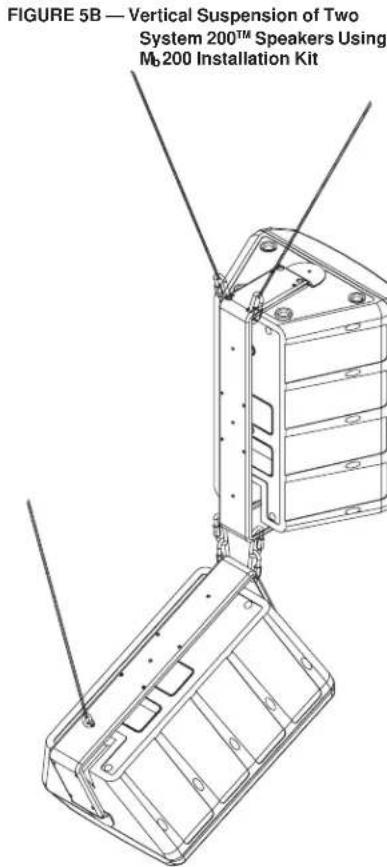
FIGURE 6A — Frame Structure for Horizontal Array in Position for Assembly (comprised of M_b200 and M_b300 brackets)
WARNING:
Suspending any object is potentially dangerous and should be attempted only by individuals who have a thorough knowledge of the techniques and regulations of rigging objects overhead. Electro-Voice sanctions suspending the System 200 ^™ speakers only when all current national, federal, state and local regulations are taken into account. When the System 200 ^™ speaker is suspended, Electro-Voice strongly recommends that system be inspected at least once a year. If any sign of weakness is detected, corrective action should be taken immediately.
FIGURE 6B — System 200 ^TM Horizontal Array (assembled)
Mb200/Mb200W Installation Kit
Limited Warranty
Electro-Voice products are guaranteed against malfunction due to defects in materials or workmanship for a specified period, as noted in the individual product-line statement(s) below, or in the individual product data sheet or owner's manual, beginning with the date of original purchase. If such malfunction occurs during the specified period, the product will be repaired or replaced (at our option) without charge. The product will be returned to the customer prepaid. Exclusions and Limitations: The Limited Warranty does not apply to: (a) exterior finish or appearance; (b) certain specific items described in the individual product-line statement(s) below, or in the individual product data sheet or owner's manual; (c) malfunction resulting from use or operation of the product other than as specified in the product data sheet or owner's manual; (d) malfunction resulting from misuse or abuse of the product; or (e) malfunction occurring at any time after repairs have been made to the product by anyone other than Electro-Voice Service or any of its authorized service representatives. Obtaining Warranty Service: To obtain warranty service, a customer must deliver the product, prepaid, to Electro-Voice Service or any of its authorized service representatives together with proof of purchase of the product in the form of a bill of sale or receipted invoice. A list of authorized service representatives is available from Electro-Voice Service at 600 Cecil Street, Buchanan, MI 49107 (800/234-6831 or FAX 616/695-4743). Incidental and Consequential Damages Excluded: Product repair or replacement and return to the customer are the only remedies provided to the customer. Electro-Voice shall not be liable for any incidental or consequential damages including, without limitation, injury to persons or prop erty or loss of use. Some states do not allow the exclusion or limitation of incidental or consequential damages so the above limitation or exclusion may not apply to you. Other
Rights: This warranty gives you specific legal rights, and you may also have other rights which vary from state to state.
Electro-Voice Accessories are guaranteed against malfunction due to defects in materials or workmanship for a period of one (1) year from the date of original purchase. Additional details are included in the Uniform Limited Warranty statement.
For warranty repair or service information, contact the service repair department at: 616/695-6831 or 800/685-2606.
For technical assistance, contact Technical Support at 800/234-6831 or 616/695-6831, M-F, 8:00 a.m. to 5:00 p.m. Eastern Standard Time.
Specifications subject to change without notice.
Specifications:
Wall Mounting Holes:
Three 8-mm ^(5)/_16 -in.) diameter holes spaced 20.3cm (8.0 in.) apart (see Figure 2)
Enclosure Mounting Holes:
Two 8-mm ( /_16 -in.) diameter holes, top and bottom
Material:
10-gauge cold-rolled steel
Finish:
Black wrinkle powdered coat
Net Weight:
3.40 kg (7.50 lb)
Shipping Weight:
3.83 kg (8.44 lb)
- Mb200
- And Mb200W Installation Kit
- Description
- Wall or Ceiling Mounting:
- Flying Installations
- System 200 TM Horizontal Arrays
- Wall Mounting Instructions
- Flying Instructions
- M_b 200 SPECIFICATION GRAPHICS
- Mb200/Mb200W Installation Kit
- WARNING:
- Limited Warranty
- Specifications:
- Wall Mounting Holes:
- Enclosure Mounting Holes:
- Material:
- Finish:
- Net Weight:
- Shipping Weight:
Brand : ELECTRO-VOICE
Model : MB200
Category : Speaker Stand