DPA5.2000D - Hi-Fi System Soundstream - Free user manual and instructions
Find the device manual for free DPA5.2000D Soundstream in PDF.


| Product Type | Car Audio Amplifier (5-Channel) |
| Brand | Soundstream |
| Model | DPA5.2000D |
| Dimensions (W x H x D) | 10.6 x 2.4 x 7.5 inches |
| Weight | 6.5 lbs (2.95 kg) |
| Power Supply | 12V DC (10-16V) |
| Peak Power Output | 2000 Watts |
| RMS Power Output | 4 x 200W @ 4Ω (Full-Range) + 1 x 800W @ 1Ω (Subwoofer) |
| Amplifier Class | Class D |
| Frequency Response | 20 Hz - 20 kHz |
| Total Harmonic Distortion (THD) | < 0.1% |
| Signal-to-Noise Ratio | > 100 dB |
| Number of Channels | 5 |
| Crossover | Variable HPF/LPF (50-500 Hz) |
| Bass Boost | 0-12 dB @ 45 Hz |
| Remote Level Control | Included (wired) |
| Input Sensitivity | 200 mV - 4 V |
| Fuse Rating | 100A (external) |
| Protection Features | Reverse polarity, thermal, short circuit, DC offset |
| Mounting Type | Horizontal or vertical |
| Certification | CEA-2006 compliant |
| Spare Parts Available | Replacement fuses, remote control (optional) |
| Maintenance | Keep clean, avoid moisture; check connections periodically |
| Repair Service | Contact Soundstream authorized service centers |
Frequently Asked Questions - DPA5.2000D Soundstream
User questions about DPA5.2000D Soundstream
0 question about this device. Answer the ones you know or ask your own.
Ask a new question about this device
Download the instructions for your Hi-Fi System in PDF format for free! Find your manual DPA5.2000D - Soundstream and take your electronic device back in hand. On this page are published all the documents necessary for the use of your device. DPA5.2000D by Soundstream.
USER MANUAL DPA5.2000D Soundstream
This symbol means important instructions.
Failure to heed them can result in serious injury or death.

WARNING
• DO NOT DRIVE WHILE DISTRACTED.
Any function that requires your prolonged attention should not be performed while driving. Always stop the vehicle in a safe location before performing any such function. Failure to do so may result in an accident.
- KEEP THE VOLUME AT MODERATE LEVELS WHILE DRIVING.
Excess volume levels can obscure sounds such as emergency vehicle sirens or road warning signals and may result in an accident. Continuous exposure to high sound pressure levels may cause permanent hearing loss. Use common sense and practice safe sound.
• FOR USE WITH 12V NEGATIVE GROUND VEHICLE APPLICATIONS ONLY.
Using this product other than in its designed application may result in fire, injury or product damage.
- MAKE THE CORRECT WIRING CONNECTIONS AND USE PROPER FUSE PROTECTION.
Failure to connect wiring correctly or use appropriate fuse protection may result in fire, injury or product damage.
• DISCONNECT THE NEGATIVE BATTERY TERMINAL BEFORE INSTALLATION.
Failure to do so may result in fire, injury or damage to the unit.
• DO NOT ALLOW CABLES TO BECOME ENTANGLED IN SURROUNDING OBJECTS.
Arrange wiring and cables to prevent obstructions when driving. Cables or wiring that obstruct or hang up on places such as steering wheel, brake pedals, etc. can be extremely hazardous.
• DO NOT DAMAGE VEHICLE SYSTEMS OR WIRING WHEN DRILLING HOLES.
When drilling holes in the chassis for installation, take precautions so as not to contact, puncture or obstruct brake lines, fuel lines, fuel tanks, electrical wiring, etc. Failure to take such precautions may result in fire or an accident.
• DO NOT UTILIZE OR CONNECT TO ANY PART OF VEHICLE SAFETY SYSTEMS.
Bolts, nuts or wires used in the brake, airbag, steering or any other safety-related systems or fuel tanks should NEVER be used for mounting, power or ground connections. Using such parts may disable control of the vehicle or result in fire.
AMPLIFIERS

CAUTION
This symbol means important instructions. Failure to heed them can result in injury or property damages.

CAUTION
• STOP USE IMMEDIATELY IF A PROBLEM OCCURS.
Failure to do so may result in personal injury or damage to the product. Return it to your authorized dealer.
• HAVE AN EXPERT DO THE WIRING AND INSTALLATION.
This unit requires special technical skill and experience for wiring and installation. To insure safety and proper function, always contact the authorized dealer where you purchased the product to have it done professionally.
• INSTALL THE UNIT SECURELY WITH SPECIFIED PARTS.
Be sure to use only the included parts and specified installation accessories (not included). Use of other than designated parts may damage this unit. Install the unit securely so that it will not come loose during a collision or sudden jolt.
- ROUTE WIRING AWAY FROM SHARP EDGES AND MOVING PARTS.
Arrange cables and wiring away from sharp or pointed edges and avoid moving parts such as seat hinges or rails to prevent pinching or wear. Use loom protection where appropriate and always use a grommet for any wiring routed through metal.
• NEVER RUN SYSTEM WIRING OUTSIDE OR UNDERNEATH THE VEHICLE.
All wiring must be routed, secured and protected inside the vehicle. Failure to do so may result in fire, injury or property damage.
• INSTALL THE UNIT IN A DRY AND VENTILATED LOCATION.
Avoid mounting locations where the unit will likely be exposed to high moisture or heat without adequate ventilation. Moisture penetration or heat buildup may result in product failure.
- REDUCE GAIN AND SOURCE VOLUME TO MINIMUM LEVELS FOR INITIAL SYSTEM TUNING AND BEFORE CONNECTION TO AN AMPLIFIER.
Ensure amplifier power is off before connecting RCA cables and follow proper system gain setting procedures. Failure to do so may result in damage to the amplifier and/or connected components.
TECHNICAL FEATURES
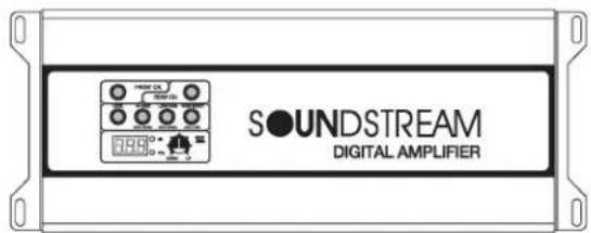
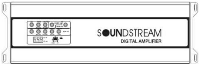
Soundstream Digital Pre-Amp amplifiers offer-up an innovative approach to traditional sound processing. DPA amps include a digital signal processing integrated circuit module that opens the door for precise tuning of crossovers & gain settings. keeping the user in mind, all functions are controlled by top surface mounted keys, needing only a finger press & knob turn. Selected crossover frequencies and gain levels are displayed on an adjacent LCD, showing operating voltage & temperature while idle. Full-featured pre-amp options, including band-pass & subsonic crossovers, bass boost, & even variable phasing make DPA amps a go-to for any enthusiast.
ADDITIONAL SPECIFICATIONS
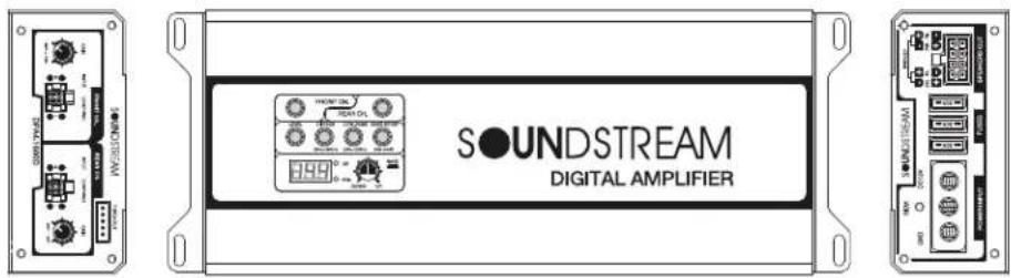
DPA4.1600D
• Additional Specifications:
• 80w x 4 @ 4-ohm Stereo
• 160w x 4 @ 2-ohm Stereo
• 320w x 2 @ 4-ohm Bridged
• 1,600w MAX Power
• 20-20kHz 48dB High Pass Crossover
• 20-20kHz 48dB Low Pass Crossover
• 0-14dB 45Hz Bass Boost Equalizer
• Total Harmonic Distortion: 0.5%(4Ω)
• Frequency Response: 10-25kHz
• Signal-to-Noise Ratio: 70dB
- Input Sensitivity: 250mV-8V
• Dimensions: 4"w x 1.75"h x 9" 1
ADDITIONAL SPECIFICATIONS
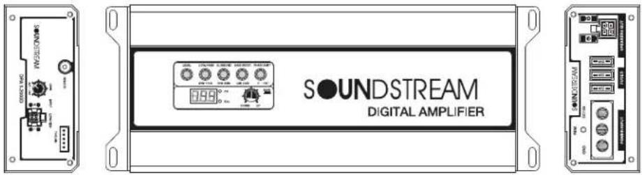
DPA1.2000D
• Additional Specifications:
• 250w x 1 @ 4-ohm Mono
• 400w x 1 @ 2-ohm Mono
• 2,000w MAX Power
• 30-250Hz 48dB Low Pass Crossover
• 10-50Hz 48dB Subsonic Crossover
• 0-14dB 45Hz Bass Boost Equalizer
• Total Harmonic Distortion: 0.5%(4Ω)
• Frequency Response: 10-1kHz
• Signal-to-Noise Ratio: 70dB
- Input Sensitivity: 250mV-8V
• Dimensions: 4"w x 1.75"h x 9" l
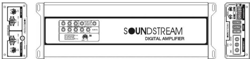
DPA5.2000D
• Additional Specifications:
- 75w x 4 (4Ω Stereo) + 200w x 1 (4Ω Mono)
- 125w x 4 (2 Ω Stereo) + 400w x 1 (2 Ω Mono)
- 250w x 2 (4 Ω Bridged) + 400w x 1 (2 Ω Mono)
• 2.000w Combined MAX Power
• 20-20kHz 48dB High Pass Crossover (ch.1-4)
• 20-20kHz 48dB Low Pass Crossover (ch.1-4)
• 20-1kHz 48dB Low Pass Crossover (ch.5)
• 10-50Hz 48dB Subsonic Crossover (ch.5)
• 0-14dB 45Hz Bass Boost Equalizer (ch.5)
- 0-180° Phase Shift (ch.5)
• Total Harmonic Distortion: 0.5%(4Ω)
• Frequency Response: 10-25kHz
• Signal-to-Noise Ratio: 70dB
- Input Sensitivity: 250mV-8V
• Dimensions: 4"w x 1.75"h x 11.5" l
FUNCTION
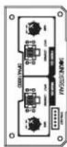
DPA4.1600D
1) Press the LED button.
2) And Press the LED Button. Ⓞ
(LED Button blinks when adjusting And LED Button is on after adjustment.)
3) Turn the volume 📋 to adjust the level. And If you think the sound is small, turn the gain on the front to make it louder.
4) It will change the level value in the display 885 it is changed from 1 to 20.
5) And press the volume 📁 to save the set value.
B) FRONT & REAR HI-PASS FITER ADJUST.
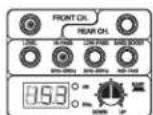
Display status
1) Press the LED button.
2) And Press the LED Button.
(LED Button blinks when adjusting And LED Button is on after adjustment.)
3) Turn the volume 📁 to adjust the level.
4) It will change the level value in the display 153° it is changed from 20Hz to 20KHz.
5) And press the volume 📂 to save the set value.
C) FRONT & REAR LOW PASS FILTER ADJUST.
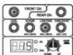
Display status
1) Press the LED button.
2) And Press the LED Button. (LED Button blinks when adjusting And LED Button is on after adjustment.)
3) Turn the volume 📋 to adjust the level.
4) It will change the level value in the display 1.15 °* it is changed from 20Hz to 20KHz.
5) And press the volume 🔍 to save the set value.
D) FRONT & REAR BASS BOOST ADJUST.
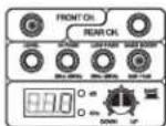
Display status
1) Press the LED button.
2) And Press the LED Button.
(LED Button blinks when adjusting And LED Button is on after adjustment.)
3) Turn the volume 📁 to adjust the level.
4) It will change the level value in the display ^0.01 , it is changed from odB to 14dB.
5) And press the volume 📁 to save the set value.
1) Press the LED button.
2) And Press the LED Button. (LED Button blinks when adjusting And LED Button is on after adjustment.)
3) Turn the volume to adjust the level.
4) It will change the level value in the display 246°. it is changed from 20Hz to 20KHz.
5) And press the volume 📁 to save the set value.
FUNCTION
DPA1.2000D
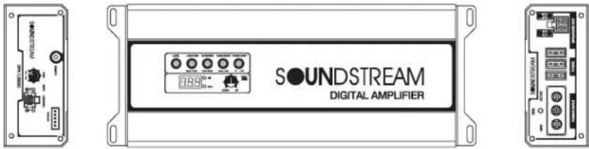
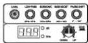
Display status
E) LEVEL ADJUST.
1) Press the LED button.
(LED Button blinks when adjusting And LED Button is on after adjustment.)
2) Turn the volume 📋 to adjust the level. There is no gain on 5 channels because of design so use the remote control.
The gain value of the remote is showed on the display and the value is changed from 1 to 25.
3) It will change the level value in the display 825 it is changed from 1 to 20.
4) And press the volume 🔍 to save the set value.
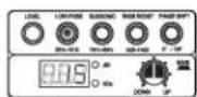
Display status
1) Press the LED button.
(LED Button is blinking when adjusting And LED Button is on after adjustment.)
2) Turn the volume ⚪ to adjust the level.
3) It will change the level value in the display ^ it is changed from 20Hz to 1KHz.
4) And press the volume 📂 to save the set value.
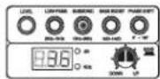
Display status
G) SUB SONIC FILTER ADJUST.
1) Press the LED button.
(LED Button is blinking when adjusting And LED Button is on after adjustment.)
2) Turn the volume 📁 to adjust the level.
3) It will change the level value in the display 188^0* it is changed from 10Hz to 50Hz.
4) And press the volume 📂 to save the set value.
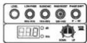
Display status
1) Press the LED button.
(LED Button is blinking when adjusting And LED Button is on after adjustment.)
2) Turn the volume 📁 to adjust the level.
3) It will change the level value in the display 8810^= it is changed from 0dB to 14dB.
4) And press the volume 📁 to save the set value.
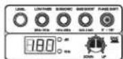
Display status
I) PHASE SHIFT ADJUST.
1) Press the LED button.
(LED Button is blinking when adjusting And LED Button is on after adjustment.)
2) Turn the volume 🚗 to adjust the level.
3) It will change the level value in the display 880^ it is changed from 0^ to 180^ .
4) And press the volume 🔊 to save the set value.
FUNCTION
DPA5.2000D
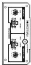
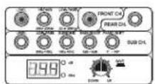
Display status
1) Press the LED button.
2) And Press the LED Button.
(LED Button blinks when adjusting And LED Button is on after adjustment.)
3) Turn the volume 🔍 to adjust the level. And If you think the sound is small, turn the gain on the front to make it louder.
4) It will change the level value in the display 888 it is changed from 1 to 20.
5) And press the volume 📁 to save the set value.
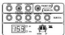
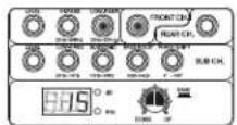
Display status
B) FRONT & REAR HI-PASS FITER ADJUST.
1) Press the LED button.
2) And Press the LED Button.
(LED Button blinks when adjusting And LED Button is on after adjustment.)
3) Turn the volume to adjust the level.
4) It will change the level value in the display 198^ . it is changed from 20Hz to 20KHz.
5) And press the volume 🔍 to save the set value.
Display status
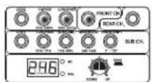
C) FRONT & REAR LOW PASS FILTER ADJUST.
1) Press the LED button.
2) And Press the LED Button.
(LED Button blinks when adjusting And LED Button is on after adjustment.)
3) Turn the volume 🔍 to adjust the level.
4) It will change the level value in the display 596^ . it is changed from 20Hz to 20KHz.
5) And press the volume 📁 to save the set value.
Display status
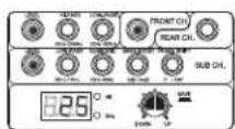
D) FRONT & REAR BAND PASS ADJUST.
1) Press the LED button.
2) And Press the LED Button.
(LED Button blinks when adjusting And LED Button is on after adjustment.)
3) Turn the volume 🔍 to adjust the level.
4) It will change the level value in the display 246°. it is changed from 20Hz to 20KHz.
5) And press the volume 🔍 to save the set value.


Display status
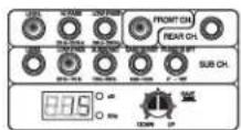
E) LEVEL ADJUST.
1) Press the LED button.
(LED Button blinks when adjusting And LED Button is on after adjustment.)
2) Turn the volume 📋 to adjust the level. There is no gain on 5 channels because of design so use the remote control. The gain value of the remote is showed on the display and the value is changed from 1 to 25.
3) It will change the level value in the display 425 it is changed from 1 to 20.
4) And press the volume 📁 to save the set value.
FUNCTION
Display status
1) Press the LED button.
(LED Button is blinking when adjusting And LED Button is on after adjustment.)
2) Turn the volume 🔍 to adjust the level.
3) It will change the level value in the display Cm^c* it is changed from 20Hz to 1KHz.
4) And press the volume 📁 to save the set value.
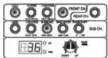
Display status
G) SUB SONIC FILTER ADJUST.
1) Press the LED button. (LED Button is blinking when adjusting And LED Button is on after adjustment.)
2) Turn the volume 📋 to adjust the level.
3) It will change the level value in the display 986^0- it is changed from 10Hz to 50Hz.
4) And press the volume 📁 to save the set value.
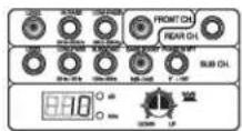
Display status
1) Press the LED button.
(LED Button is blinking when adjusting And LED Button is on after adjustment.)
2) Turn the volume 📋 to adjust the level.
3) It will change the level value in the display . it is changed from 0dB to 14dB.
4) And press the volume 🔍 to save the set value.
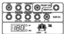
Display status
I) PHASE SHIFT ADJUST.
1) Press the LED button.
(LED Button is blinking when adjusting And LED Button is on after adjustment.)
2) Turn the volume 🔍 to adjust the level.
3) It will change the level value in the display 180^ , it is changed from 0^ to 180^ .
4) And press the volume 📁 to save the set value.
DISPLAY DESCRIPTION
1) Thermal protection.
a. The thermal protection circuit is worked when the temperature of the product reaches 160F degrees. And the display will show as above and it will again work when the temperature drops 50F degrees.
2) Voltage and temperature indication.
a. The default is voltage.
0.99°
0°
b. Press shortly the volume Then the display will change from voltage to temperature.
199°→86F°→199°
b. Press longer the volume 📁 Then the display will change from Celsius to Fahrenheit.
300° ⇒ 860° ⇒ 900°
3) How to reset.
a. If there is a problem with the product, press the volume more than 10 seconds.
FUNCTION
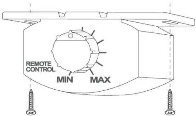
REMOTE SUBWOOFER LEVEL CONTROL
This input allows you to add remote that will allow you to control the subwoofer output of your SoundStream amplifier from your dashboard. and to adapt the amplifier to all kind of signal sources with varying levels there are a level control provided on the amplifier next to the phone jacks. It should not be used as volume controls. Start with a "12" clock" setting of the level controls. If you set the head unit volume to 75% of maximum you should achieve a good sound without distortion. Find a point of the level setting where the distortion is just discernible. At this point slightly reduce the control.
HOW TO INSTALLATION
The dash control mounts with two screws, which attach to the underside of the dashboard. Slide under the dash and place the dash control in its mounting position, mark the two mounting holes, drill pilot holes, and secure with two screws.
How to connect hi-input and low-input mode.
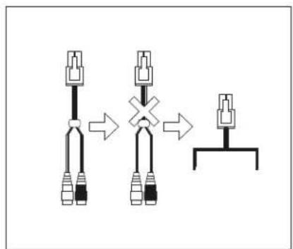
The input can use both hi- input and low- inputs.
When connecting by Hi-input, use the cable provided by the manufacturer as shown.
flowchart
graph TD
    A["Initial Setup"] --> B{Cross-Circuit Operation}
    B --> C["Final Assembly"]
    style A fill:#f9f,stroke:#333
    style B fill:#ccf,stroke:#333
    style C fill:#cfc,stroke:#333
How to make a high input connector.
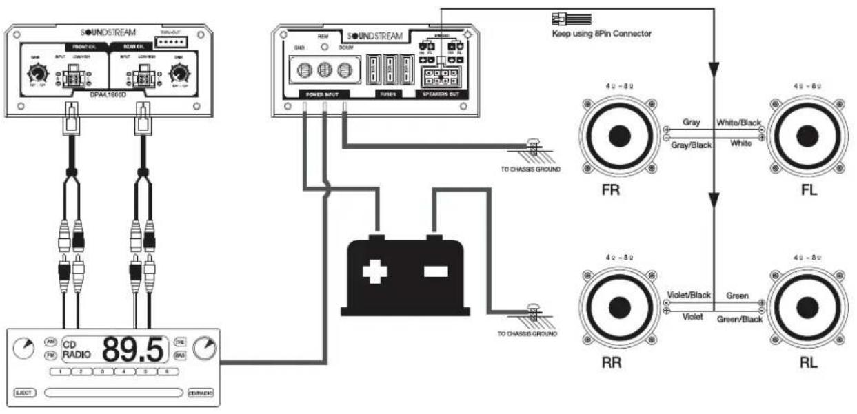
| DPA4.1600D | ||
| 80W x 4ch. | 4Ohm. | 14.4V 1Khz RMS. |
| 160W x 4ch. | 2Ohm. | 14.4V 1Khz RMS. |
| 320W x 2ch. | 4Ohm. | 14.4V 1Khz RMS. |
| 1.600W | MAX POWER | |
How to connect hi-input and low-input mode.
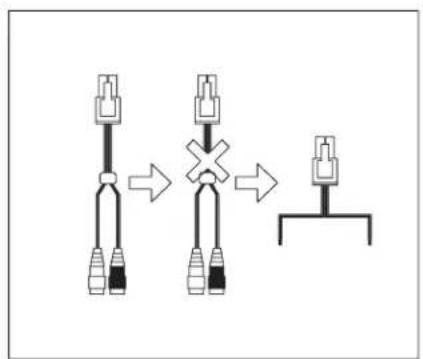
The input can use both hi- input and low- inputs.
When connecting by Hi-input, use the cable provided by the manufacturer as shown.
flowchart
graph TD
    A["Connector"] --> B["Switch"]
    B --> C["Final Connector"]
How to make a high input connector.
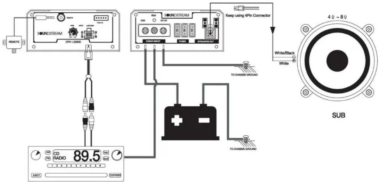
| DPA1.2000D | ||
| 250W x 1ch. | 4Ohm. | 14.4V 100Hz RMS. |
| 400W x 1ch. | 2Ohm. | 14.4V 100Hz RMS. |
| 2.000W | MAX POWER | |
5-channel gain control method.
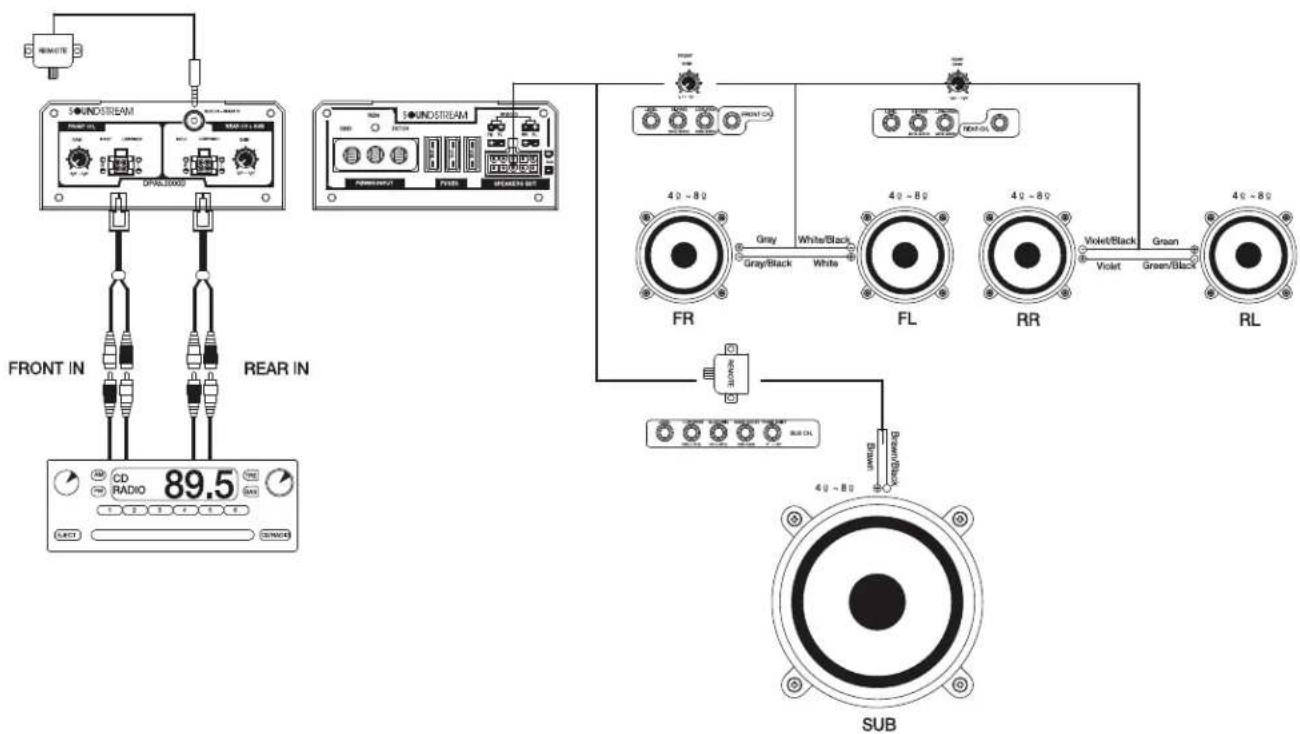
flowchart
graph TD
    A["FR"] -->|Gray/Black| B["FL"]
    B -->|White/Black| C["RR"]
    C -->|Violet/Black| D["RL"]
    D -->|Green/Black| E["SUB"]
    F["FRONT IN"] --> G["CD/RADIO 89.5"]
    H["REAR IN"] --> I["Switch"]
    J["40-80"] --> K["FR"]
    L["40-80"] --> M["FL"]
    N["40-80"] --> O["RR"]
    P["40-80"] --> Q["RL"]
You can increase the output by raising the level of the top panel. And you must connect the remote control to increase the more output.
| DPA5.2000D | ||
| 75W x 4ch. | 4Ohm. | 14,4V 1Khz RMS. |
| 125W x 4ch. | 2Ohm. | 14,4V 1Khz RMS. |
| 250W x 2ch. | 4Ohm. | 14,4V 1Khz RMS. |
| 200W x 1ch. | 4Ohm. | 14,4V 100Hz RMS. |
| 400W x 1ch. | 2Ohm. | 14,4V 100Hz RMS. |
| 2,000W | MAX POWER | |
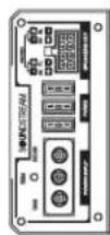
These amplifiers are designed to work within a 10 to 16.8 volt DC range. Before any wires are connected, the vehicles electrical system should be checked for correct voltage supply with the help of a voltmeter.
First, check the voltage at the battery with the ignition in the OFF position. The voltmeter should read no less than 12V. If your vehicles electrical system is not up to these specifications, we recommend having it checked by an auto electrician before any further installation. Once the vehicle is checked, make certain the correct cable size is used. We recommend using as large a gauge cable as possible, use the Power Cable Selection Chart to calculate the correct power wire size for your application.
Power
This amplifier should be wired directly to the vehicle battery using the appropriate size cable. Start at the vehicle battery and run the power cable through to the amplifier. Avoid running the power cable over engine components and near heater cores. The use of an inline fuse or circuit breaker is a must; this will prevent the risk of a potential fire caused by a short in your power cable. Connect the fuse holder or circuit breaker as close to the battery positive (+) terminal as possible (no farther then 18" from the battery). This fuse or circuit breaker should be no greater than the sum of the fuses found on the chassis of your amplifier (also see specifications chart). You may now connect the cable to the battery, but remember to leave the fuse out or circuit breaker "off" until all other cable connections are made.
Ground
When grounding your amplifier, locate a metal area close to the amplifier that is good source of ground (preferably the floor pan). Once again, investigate the area you wish to use for electrical wires, vacuum lines, and brake or fuel lines. Use either a wire brush or sandpaper to eliminate unwanted paint for better contact of the ground. Secure the ground cable to the body using a bolt, star washer and nut. Spread silicon over the screw and bare metal to prevent rust and possible water leaks.
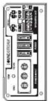
Now it's time to connect the power and ground cables to the amplifier. Cut both cables to length. Strip off 1/2-inch (12mm) of the insulation so that the bare wire fits all the way in the terminal block on the side panel of the amplifier, seating it firmly so no bare wire is exposed. Use a Philips (cross) type screwdriver to loosen the +BATT and the GND connections on the amplifier. Insert the ground first, and then the +12V and please make sure that you place them into the correctly marked terminals. Then tighten the screws down securely.
Remote
This terminal must be connected to a switched +12V source. Typically, remote turn-on leads are provided at the source unit that will turn on and off the amplifier in correspondence with the source. If the source unit does not have a remote turn-on lead, then a power antenna wire can be used. If neither of these leads is available at the source unit, then a switched +12V supply must be used, like the ACC, +12V.
REMOTE WIRE
Some signal cables include a thin wire for remote amplifier start. High quality cables normally requires a separate wire for this. Connect between the head units remote cable (often the same cable that's used for automatic power antennas) and the REM-terminal on the amplifier.
NOTE! If you want to start more than one amplifier using the remote output, the current load might be too high for some head units. High currents may damage the head unit, check in the manual for the head unit. Sometimes you must add a relay to the remote circuit that takes care of the higher current. If you are uncertain of how to connect the relay, ask your local DLS dealer for advice.
SPEAKER CONNECTION
Always use high quality speaker cables. Connect the speaker + (marked with + or a red dot) to the amplifier + terminal, and the speaker
When fitting the cables to the terminals, remove only 10 mm of the insulation. Twist the wire strand together and insert the wire after loosening the terminal screw. Do not over tighten as this can cut the cable strands. To prevent the cable insulation from beeing damaged over sharp metal edges we recommend the use of cable protection tubes or similar. A damaged cable insulation could cause serious damage to the amplifier not covered by any guarantee.
SPEAKER POLARITY CHECK
All speakers in a car audio system should be connected in phase (the same polarity). All speaker cones must move in the same direction. Out of phase speakers will cause a lack of bass, and a poor stereo soundstage.
SOUNDSTREAM
R E S E R V E

WARNING: This product can expose you to chemicals including DEHP which is known to the State of California to cause Cancer, Birth Defects or other reproduction harm. For more information go to www.P65warnings.ca.gov.
- WARNING
- • DO NOT DRIVE WHILE DISTRACTED.
- - KEEP THE VOLUME AT MODERATE LEVELS WHILE DRIVING.
- • FOR USE WITH 12V NEGATIVE GROUND VEHICLE APPLICATIONS ONLY.
- - MAKE THE CORRECT WIRING CONNECTIONS AND USE PROPER FUSE PROTECTION.
- • DISCONNECT THE NEGATIVE BATTERY TERMINAL BEFORE INSTALLATION.
- • DO NOT ALLOW CABLES TO BECOME ENTANGLED IN SURROUNDING OBJECTS.
- • DO NOT DAMAGE VEHICLE SYSTEMS OR WIRING WHEN DRILLING HOLES.
- • DO NOT UTILIZE OR CONNECT TO ANY PART OF VEHICLE SAFETY SYSTEMS.
- AMPLIFIERS
- CAUTION
- TECHNICAL FEATURES
- ADDITIONAL SPECIFICATIONS
- DPA4.1600D
- DPA1.2000D
- DPA5.2000D
- FUNCTION
- B) FRONT & REAR HI-PASS FITER ADJUST.
- C) FRONT & REAR LOW PASS FILTER ADJUST.
- D) FRONT & REAR BASS BOOST ADJUST.
- E) LEVEL ADJUST.
- G) SUB SONIC FILTER ADJUST.
- I) PHASE SHIFT ADJUST.
- D) FRONT & REAR BAND PASS ADJUST.
- DISPLAY DESCRIPTION
- REMOTE SUBWOOFER LEVEL CONTROL
- HOW TO INSTALLATION
- How to connect hi-input and low-input mode.
- Power
- Ground
- Remote
- REMOTE WIRE
- SPEAKER CONNECTION
- SPEAKER POLARITY CHECK
- SOUNDSTREAM
Brand : Soundstream
Model : DPA5.2000D
Category : Hi-Fi System