975 - Uncategorized FLUKE - Free user manual and instructions
Find the device manual for free 975 FLUKE in PDF.


| Product Type | Air Velocity, Temperature, and Humidity Meter (AirMeter) |
| Brand | Fluke |
| Model | 975 |
| Category | HVAC & Environmental Test Tool |
| Dimensions (H x W x D) | 7.8 x 4.2 x 2.4 in (19.8 x 10.7 x 6.1 cm) |
| Weight | 1.2 lb (0.54 kg) with batteries |
| Power Supply | 4 AA alkaline batteries (1.5 V) or optional AC adapter |
| Battery Life | Approximately 12 hours (low battery indicator) |
| Display | Backlit LCD with dual display |
| Air Velocity Range | 0 to 20 m/s (0 to 3937 ft/min) |
| Temperature Range | -10°C to 50°C (14°F to 122°F) |
| Humidity Range | 5% to 95% RH, non-condensing |
| Accuracy (Air Velocity) | ±(3% reading + 0.04 m/s) or ±(3% reading + 8 ft/min) |
| Accuracy (Temperature) | ±0.5°C (±0.9°F) |
| Accuracy (Humidity) | ±2% RH (10% to 90% RH) |
| Calculated Parameters | Dew point, Wet bulb temperature, Air volume |
| Data Logging | Up to 99 readings via memory |
| Interface | Optical isolated USB |
| Safety Rating | EN 61326-1 (EMC), Measurement Category I |
| Operating Temperature | 0°C to 40°C (32°F to 104°F) |
| Storage Temperature | -20°C to 60°C (-4°F to 140°F) |
| Maintenance | Clean with a soft, damp cloth; do not use solvents |
| Included Accessories | Carrying case, 4 AA batteries, manual, USB cable |
Frequently Asked Questions - 975 FLUKE
User questions about 975 FLUKE
0 question about this device. Answer the ones you know or ask your own.
Ask a new question about this device
Download the instructions for your Uncategorized in PDF format for free! Find your manual 975 - FLUKE and take your electronic device back in hand. On this page are published all the documents necessary for the use of your device. 975 by FLUKE.
USER MANUAL 975 FLUKE
August 2006 Rev. 1, 12/11
© 2006-2011 Fluke Corporation. All rights reserved. Printed in U.S.A. Specifications subject to change without notice.
All product names are trademarks of their respective companies.
LIMITED WARRANTY AND LIMITATION OF LIABILITY
Each Fluke product is warranted to be free from defects in material and workmanship under normal use and service. The warranty period is 2 years and begins on the date of shipment. Parts, product repairs, and services are warranted for 90 days. This warranty extends only to the original buyer or end-user customer of a Fluke authorized reseller, and does not apply to fuses, disposable batteries, or to any product which, in Fluke's opinion, has been misused, altered, neglected, contaminated, or damaged by accident or abnormal conditions of operation or handling. Fluke warrants that software will operate substantially in accordance with its functional specifications for 90 days and that it has been properly recorded on non-defective media. Fluke does not warrant that software will be error free or operate without interruption.
Fluke authorized resellers shall extend this warranty on new and unused products to end-user customers only but have no authority to extend a greater or different warranty on behalf of Fluke. Warranty support is available only if product is purchased through a Fluke authorized sales outlet or Buyer has paid the applicable international price. Fluke reserves the right to invoice Buyer for importation costs of repair/replacement parts when product purchased in one country is submitted for repair in another country.
Fluke's warranty obligation is limited, at Fluke's option, to refund of the purchase price, free of charge repair, or replacement of a defective product which is returned to a Fluke authorized service center within the warranty period.
To obtain warranty service, contact your nearest Fluke authorized service center to obtain return authorization information, then send the product to that service center, with a description of the difficulty, postage and insurance prepaid (FOB Destination). Fluke assumes no risk for damage in transit. Following warranty repair, the product will be returned to Buyer, transportation prepaid (FOB Destination). If Fluke determines that failure was caused by neglect, misuse, contamination, alteration, accident, or abnormal condition of operation or handling, including overvoltage failures caused by use outside the product's specified rating, or normal wear and tear of mechanical components, Fluke will provide an estimate of repair costs and obtain authorization before commencing the work. Following repair, the product will be returned to the Buyer transportation prepaid and the Buyer will be billed for the repair and return transportation charges (FOB Shipping Point).
THIS WARRANTY IS BUYER'S SOLE AND EXCLUSIVE REMEDY AND IS IN LIEU OF ALL OTHER WARRANTIES, EXPRESS OR IMPLIED, INCLUDING BUT NOT LIMITED TO ANY IMPLIED WARRANTY OF MERCHANTABILITY OR FITNESS FOR A PARTICULAR PURPOSE. FLUKE SHALL NOT BE LIABLE FOR ANY SPECIAL, INDIRECT, INCIDENTAL, OR CONSEQUENTIAL DAMAGES OR LOSSES, INCLUDING LOSS OF DATA, ARISING FROM ANY CAUSE OR THEORY.
Since some countries or states do not allow limitation of the term of an implied warranty, or exclusion or limitation of incidental or consequential damages, the limitations and exclusions of this warranty may not apply to every buyer. If any provision of this Warranty is held invalid or unenforceable by a court or other decision-maker of competent jurisdiction, such holding will not affect the validity or enforceability of any other provision.
Fluke Corporation
P.O. Box 9090
Everett, WA 98206-9090
U.S.A.
Fluke Europe B.V.
P.O. Box 1186
5602 BD Eindhoven
The Netherlands
Table of Contents
Title
Page
Introduction....1
Features 1
Contacting Fluke 2
Safety Information 2
Symbols.... 3
Shipping Contents 4
Using the Meter 6
Using the Meter 6
Softkeys and Pushbuttons....6
Meter Power 7
Meter Power 7
Startup and Self Test....8
Automatic Backlight 9
Automatic Power Off....9
Multi-Language Interface.... 10
Measurement Units 10
Time and Date Stamp.... 10
CO Alarm....10
The Setup Menu 10
Taking Measurements 11
Temperature, Relative Humidity, CO, CO_2 , Dew Point, and Wet Bulb
Measurements 11
% Outside Air 11
% Outside Air (Temperature).... 12
% Outside Air (CO _2 ) 12
Air Velocity and Volume Flow Rate 13
Standard Velocity and Actual Velocity 13
Velocity Probe 13
Measuring Air Velocity.... 13
Measuring Volume Flow Rate 14
Min Max Avg 15
Data Logging 15
Saving Single-Point Data 15
Continuous Data Logging.... 16
Logging Button Lockout 17
Recalling or Erasing Logged Data.... 18
Transferring Data to a Personal Computer 19
Calibration....20
Calibrating the CO and CO2 Sensors 20
Calibrating the CO Sensor 21
Calibrating the CO₂ Sensor 21
Maintenance 24
Cleaning the Meter 24
Battery Maintenance and Battery Charge Indicators 24
Charging the Battery and Using the Power Adapter 25
Changing the AA Batteries 25
Contents
(continued)
General Specifications 27
Calculated Parameters 28
Environmental Specifications.... 29
Physical Specifications 29
Agency Approvals, Certifications and Standards Compliance 30
Replaceable Parts and Accessories.... 30
Users Manual
iv
List of Tables
Table Title Page
- Symbols....3
- 975 Shipping Contents .... 5
- Softkeys and Pushbuttons....6
- Startup Failure Messages....9
- Gas for Calibration.... 20
- Replaceable Parts and Accessories 32
Users Manual
List of Figures
Figure Title Page
- 975 Shipping Contents .... 4
- Softkeys and Pushbuttons....6
- AC Adapter Input and USB Port 8
- Calibration Set Up 23
- AA Battery Replacement and Kensington Lock Use 26
- Replaceable Parts and Accessories 31
Users Manual
viii
Introduction
⚠ Warning
Read "Safety Information" before using the 975 AirMeter™ Test Tool.
The Fluke 975 AirMeter™ Test Tool ("the Meter") is a hand-held, five-sensor indoor air quality diagnostic instrument. It measures, calculates, and displays:
- Temperature, dew point, and wet bulb all measured in Celsius (°C) or Fahrenheit (°F).
• Relative humidity (%RH).
• Carbon monoxide (CO) levels measured in ppm.
• Carbon dioxide (CO 2 ) levels measured in ppm.
• Air velocity (standard and actual) measured in mps or fpm.
• % outside air based on temperature or CO 2 . - Flow rate displayed in m ^3 /s or cfm.
- Absolute barometric pressure- shown at startup only.
- Minimum, maximum, and average readings for temperature, relative humidity, wet bulb, dew point, velocity, CO, and CO₂.
Features
Detailed explanations of the Meter features appear later in this manual. The Meter comes with the following features:
• Automatic backlight
- Auto power off
- Rechargeable lithium battery, ac power, or backup power supply of three AA batteries
• DC power supply with available international adapters
- Multi-language user interface (English, French, German, Portuguese, and Spanish)
• US and Metric measurement options
• Time and date stamp (12-hour or 24-hour)
- Single-point and continuous data logging options
- CO alarm
- Detachable velocity probe (optional)
- FlukeView® Forms software with USB cable for downloading stored data
- Hard shell carrying case
• Protective holster
• Calibration cap and tubing
• Calibration certificate for NIST traceability
• Kensington lock-ready. See Figure 5.
Contacting Fluke
To contact Fluke, call one of the following telephone numbers:
• Technical Support USA: 1-800-44-FLUKE (1-800-443-5853)
• Calibration/Repair USA: 1-888-99-FLUKE (1-888-993-5853)
• Canada: 1-800-36-FLUKE (1-800-363-5853)
• Europe: +31 402-675-200
• Japan: +81-03-6714-3114
• Singapore: +65-738-5655
• Anywhere in the world: +1-425-446-5500
Or, visit Fluke's website at www.fluke.com.
To register your product, visit http://register.fluke.com.
To see, print, or download the latest manual supplement, visit http://us.fluke.com/usen/support/manuals.
Safety Information
A Warning identifies a condition or action that pose hazard(s) to the user; a Caution identifies a condition or action that may damage the Meter or the equipment under test.
Warning
To avoid injury, or damage to the Meter, follow these safety guidelines:
- Read the entire users manual before using the Meter.
- Use the Meter only as described in the Users Manual otherwise the protection provided by the equipment may be impaired.
- Inspect the Meter before use. Do not use it if it appears damaged.
- The Meter contains no user-serviceable parts. Do not open the instrument. For service and rechargeable-battery replacement, the instrument must be sent to Fluke. See "Contacting Fluke".
- Have the Meter serviced only by qualified service personnel.
- Always use the ac adapter/charger and connector (supplied with the Meter) appropriate for the voltage and outlet of the country or location in which you are working.
Caution
To avoid possible damage to the Meter, avoid using the Meter in an excessively dirty or dusty atmosphere. Excessive particle intake can damage the Meter.
Symbols
Symbols used in this manual and on the Meter are displayed in Table 1.
Table 1. Symbols
| Symbol | Meaning | |
| [R4K7X] Risk of danger. Important information. Refer to manual. | ||
 Hazardous voltage. Risk of electrical shock. Hazardous voltage. Risk of electrical shock. | ||
| CE Conforms to relevant European Union directives | ||
 Conforms to Australian Standards Conforms to Australian Standards | ||
| [A20T] | The Meter battery contains Lithium. Do not dispose of this battery as unsorted municipal waste. Contact Fluke or a qualified recycler for disposal. | |
| [5Kx5] | Do not dispose of this product as unsorted municipal waste. Contact Fluke or a qualified recycler for disposal. | |
 RC Rechargeable battery symbol RC Rechargeable battery symbol | ||
 AA Backup battery symbol AA Backup battery symbol | ||
Shipping Contents
The Meter ships with the items shown in Figure 1 and listed in Table 2.
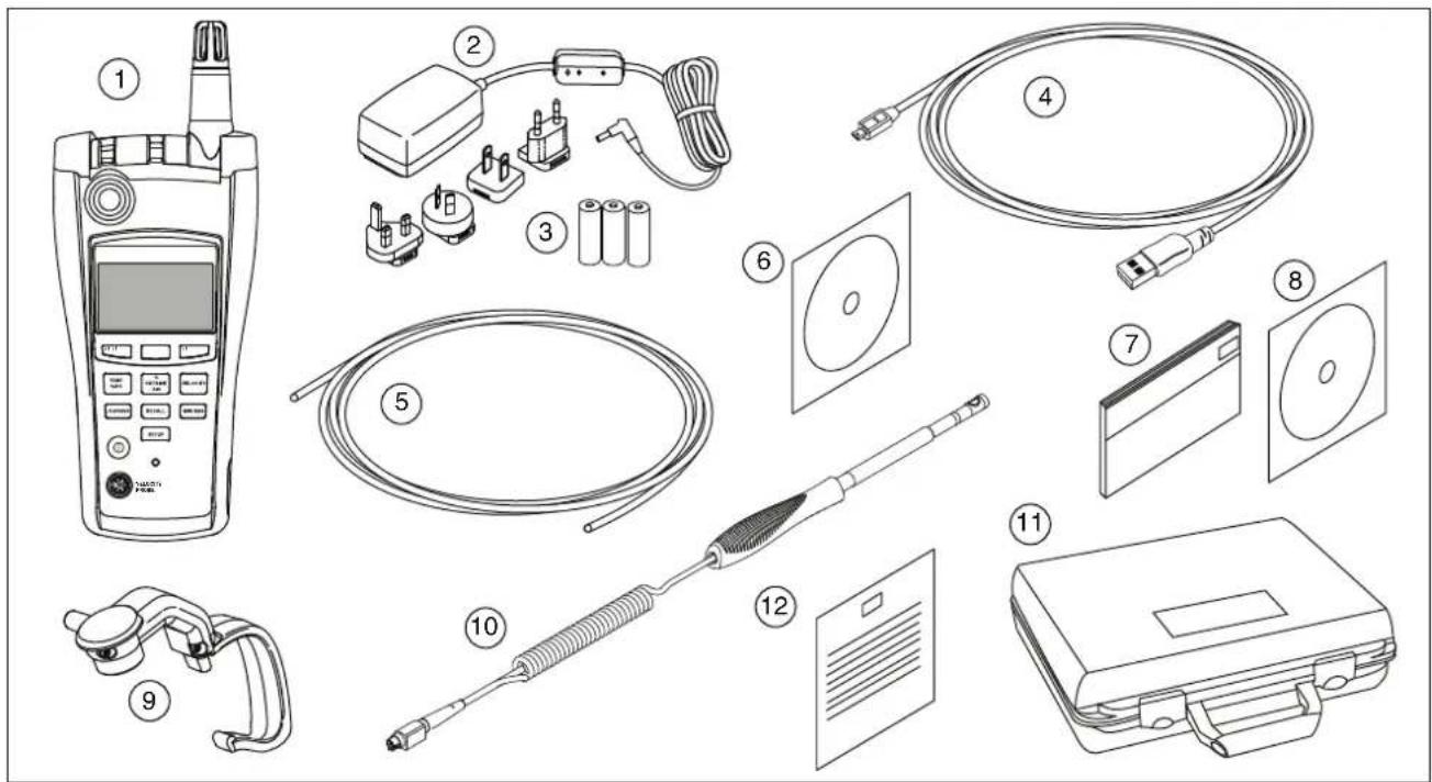
Figure 1. 975 Shipping Contents
eba07f.eps
Table 2. 975 Shipping Contents
| Item | Description | Item Description | |
| 1 | 975 AirMeterTM Test Tool and Holster | 7 | Users Manual (printed, English) |
| 2 | AC Adapter/Charger with type A, C, G and I adapters to fit most countries. | 8 | 975 Manuals CD containing the Users Manual in English, French, German, Portuguese, Spanish, and Simplified Chinese |
| 3 | Three AA batteries (backup power supply) | 9 | CO and CO2 calibration cap |
| 4 | USB cable | 10 | Velocity probe (optional) |
| 5 | Tubing for calibration | 11 | Hard shell carrying case |
| 6 | FlukeView® Forms software CD and documentation | 12 | Calibration certificate |
Using the Meter
The following sections explain how to use the Meter and its features.
Softkeys and Pushbuttons
Use the softkeys to navigate among different menus or to select different functions. Softkeys F1, F2, and F3 correspond to prompts in the lower section of the display. Refer to Figure 2 and Table 3. Use the pushbuttons to select different Meter functions.
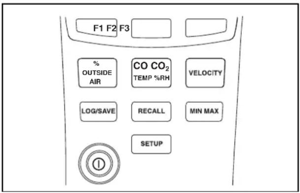
Figure 2. Softkeys and Pushbuttons
Table 3. Softkeys and Pushbuttons
| Softkey or Pushbutton | Function |
| Softkeys- Each softkey corresponds to prompts on the lower section of the display. The prompts change depending on what function menu is used. | |
| CO and CO2Temperature/ % Relative Humidity- Activates the Temperature, Relative Humidity, CO and CO2, Wet Bulb, and Dew Point functions. | |
| % Outside Air- Activates the % Outside Air menu. See “% Outside Air”. | |
| Velocity-When used with the optional Velocity Probe, this activates the Air Velocity and Volume Flow Rate menus. See “Air Velocity and Volume Flow Rate”. | |
| Log/Save- Activates the Log/Save menus. See “Data Logging”. | |
| Recall- Press this button to access the Logged Data menu. See “Recalling or Erasing Logged Data”. | |
| MIN MAX- Activates the Min Max Avg function. See “Min Max Avg”. | |
| Power- Turns the Meter on and off. | |
| Setup- Press to enter the Setup menu. See “The Setup Menu”. |
Meter Power
Warning
To avoid electrical shock or personal injury, always match the line cord to the instrument.
- Use the line cord supplied for this instrument with this instrument only.
- Do not use this line cord with any other instruments.
- Do not use any other line cords with this instrument.
- Use the proper line cord and adapter for your country.
- Do not replace the Lithium battery. For Lithium battery replacement, the Meter must be sent to Fluke. See "Contacting Fluke".
The Meter is powered by a rechargeable lithium battery, a supplied ac adapter, or three AA batteries used as a backup power supply. See Figure 3 to locate the ac power input.
Note
Before the rechargeable battery can be used, it must first be charged for several hours. If immediate Meter use is necessary, the backup batteries or the line cord can be used.

Note
This Meter contains a lithium battery.
Do not mix with the solid waste stream. Spent batteries should be disposed of by a qualified recycler or hazardous materials handler.
Contact your authorized Fluke Service Center for recycling information.
A fully-charged Meter operates for 11 hours. The backup power supply lasts 7 hours.
See "Maintenance" for information on how to charge the Lithium battery and how to change the AA batteries.
Note
The adapter/charger includes adapters that fit receptacles in most countries.
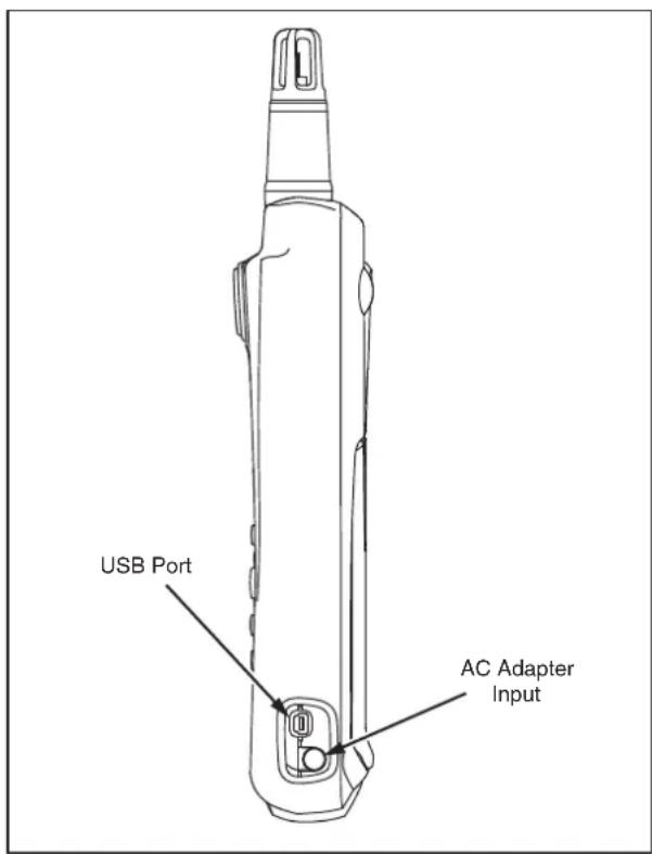
Figure 3. AC Adapter Input and USB Port
eba02f.eps
Startup and Self Test
To turn the Meter on, press and hold ① for a few seconds and wait for the flashing red LED on the left side of the display. Press ① for 2 seconds to turn the Meter OFF. Once powered up, the following information is displayed:
- Battery charge indicators
• Model number of the Meter (975) - Firmware version number
- Current date
- Last calibration date
- Calibration due date
• Absolute barometric pressure
• Self-test countdown
At power up, the Meter performs a 35-second self-diagnostic test for each of its functions. When it passes the self-test, the Meter is ready for use. Refer to Table 4 for a list of self-diagnostic test failures.
Note
If portions of the self-test fail, some functions of the Meter may still be used but this is not recommended. Have the Meter serviced immediately. Refer to "Contacting Fluke" for service details.
Table 4. Startup Failure Messages
| Failure Message Action | |
| Temperature Sensor: FAILHumidity Sensor: FAIL | Have the Meter serviced. The Meter may still be used. Wet bulb, Dew point, Temperature and Humidity functions are unavailable. CO or CO_2 readings are inaccurate. |
| CO: FAIL CO_2 : FAIL | Have the Meter serviced. The Meter may still be used. CO or CO_2 functions are unavailable. If either sensor fails, then calculations are incomplete. |
| ⚠ SELF TEST: FAILEDPlease Service Instrument | Have the Meter serviced. The Meter has internal failures.Message appears until the Meter is serviced. |
| Battery EmptySystem is ShuttingDown... | If the battery is below minimum charge, the Meter shuts down until the battery is recharged or the Meter is connected to ac power. See “Battery Maintenance”. |
| PROBE ERROR | Problem with the Velocity probe or the connection. Remove and reattach the probe. If the problem continues, have the probe serviced. |
| ⚠ Calibration OVERDUEPlease Refer to Manual | Calibrate the Meter. Calibration date for the Meter has passed. See “Calibration”. |
Note
The Meter settling time is less than 1 minute. Severe changes or differences in temperature between the Meter and the measuring environment may require more settling time.
Automatic Backlight
The Meter's backlight senses low-light conditions and automatically turns on when necessary. The backlight turns off after 30 seconds of Meter inactivity. To turn it back on, press any button. The button pressed will not activate its normal function. In low light, any button pressed will turn the backlight on for 30 seconds. See "The Setup Menu" to disable the auto backlight off.
Automatic Power Off
To conserve battery power, the Meter goes into sleep mode after 20 minutes of non-use and remains in this mode for 12 hours. After 12 hours in sleep mode, the Meter completely shuts down. Use the Setup menu to disable this function or to select 30 or 60 minute time out periods. See “The Setup Menu”. Automatic power off is disabled during logging.
Multi-Language Interface
The Meter's display supports five languages: English, French, German, Portuguese, and Spanish. Use the Setup menu to change the display language. See "The Setup Menu".
Measurement Units
The Meter supports both Metric and US measurement units. Select the desired measurement format using the Setup menu. See "The Setup Menu".
Time and Date Stamp
The Meter features an on-board, user settable clock that logs the time and date for each captured reading. The current date is displayed when the Meter is powered on. The Meter continues to keep time when it is powered off. To change the time and date format, see "The Setup Menu".
CO Alarm
The Meter is equipped with a CO alarm. By default, the alarm is reset to 35 ppm every time the Meter is turned off. Using the Setup Menu, set the alarm threshold anywhere from 1 ppm to 200 ppm. When the amount of carbon monoxide exceeds the limit, the alarm triggers. The Meter emits an audible alarm and a red LED flashes. See “The Setup Menu”.
The Setup Menu
Use the Setup menu to change the following Meter parameters:
- Set Time
- Set Time Format: 12 or 24 hour modes
- Set Date
- Set Date Format: M/D/Y or D/M/Y
• Temperature Scale: °C or °F
• Measurement Units: Metric or US
- CO Alarm: specifies measurement at which the alarm sounds from 1 ppm to 200 ppm
- Auto Power Off
- Calibration Cycle (1-365 days) [user-configurable]
- Backlight: enables or disables auto backlight off
- Language: the user interface language can be changed to English, French, German, Portuguese, or Spanish.
- Keypad Beep: enables or disables the keypad beeper. The CO alarm is not affected.
To modify the Meter setup parameters:
-
From any screen, press SETUP to enter the Setup menu editing mode.
-
Press F1 ▼ Item] and F2 [▲ Item] to highlight a listed setup item.
-
Press F3 [Select] to make the desired item active.
-
Press F1 and F2 as necessary to change the item values. Hold down F1 or F2 to increase the rate of change.
- Press F3 [Select], or in some cases [Done], to store the changes.
- Press SETUP for 2 seconds to exit the Setup menu. All changes are stored.
Taking Measurements
The Meter measures:
• Temperature, Dew Point, and Wet Bulb
• Relative Humidity (%RH)
• Carbon monoxide (CO) levels
• Carbon dioxide (CO _2 ) levels
- % Outside Air
• Air Velocity (standard and actual)
- Flow Rate
Temperature, Relative Humidity, CO, CO₂, Dew Point, and Wet Bulb Measurements
When the Meter completes and passes its self-test, it is ready to take temperature, relative humidity, CO, CO₂, dew point, and wet bulb readings. If the Meter is displaying another function menu, press [ CO_2120% · KH] .
Temperature, relative humidity, CO, and CO_2 readings are shown on this screen.
- Dew point is the temperature at which condensation starts. To view the dew point from the main menu,
press F1 [Dew Point]. The dew point reading appears on the top right of the display.
- Wet bulb temperature is the lowest temperature that evaporating water can reach. To view the wet bulb temperature from the main menu, press F3 [Wet Bulb] (or F1 [Wet Bulb] if the Meter is displaying dew point temperature). The wet bulb reading appears on the top right of the display.
From either the wet bulb or dew point screens, press F3 [Main] to return to the main screen.
% Outside Air
Air conditioning systems rely on outside air, mixed air, and return air to help cool, heat, or purify their output. A balance of the three is also a factor in achieving optimum-energy usage from the conditioning unit.
The Meter's Percentage (%) Outside Air function computes the percentage of outside air two different ways, either by measuring temperature or by measuring CO_2 content.
The formula for calculating % outside air is:
$$ \% \text {Outside Air} = \frac {\left(\text {Return Air} - \text {Mixed Air}\right) \times 100 \%}{\text {Return Air} - \text {Outside Air}} $$
Determining the \% outside air requires entering values for return air, outside air, and mixed air into the formula. These values can be in temperature or CO_2 content. The values can be measured with the Meter or, in the case of outside air, can also be entered manually. Once the
variables are known, the Meter computes the % outside air.
% Outside Air (Temperature)
To obtain % of outside air using temperature:
- Place the Meter sensor perpendicular to the air stream being measured.
- Press ☐ The Meter switches to % outside air measuring mode and offers choices of F1 [CO₂] or F3 [Temp].
- Press F3 [Temp]. The Meter measures and displays the return air temperature.
- Press F1 [Capture] store the return air reading. The Meter then measures and displays the mixed air temperature.
- Press F1 [Capture] store the mixed air reading. The Meter then measures and displays the outside air temperature.
- Outside air temperature can either be measured by using F1 [Capture] or it can be entered manually by pressing F2 [Manual Entry] and entering the known outside air temperature value. When entering manually, use F2 [UP] and F3 [DOWN] to change the temperature reading to the desired number. Press F1 [ENTER].
- Once the outside air temperature is entered, return air, mixed air, and outside air temperatures are displayed. Press F1 [Calculate] to show the %
outside air, or press F3 [Back] to change any of the measurements.
- Press F3 [Done] to end the % outside air measurement.
% Outside Air (CO₂)
Measuring the \% outside air using carbon dioxide (CO _2 ) is similar to measuring the percentage of outside air via temperature.
To obtain the \% outside air using CO_2 :
- Place the Meter sensor perpendicular to the air stream being measured.
- Press AIR . The Meter switches to the % outside air measuring mode and offers the selection choice of 1 [CO_2] or 3 [Temp] .
- Press F1 [C2]. The Meter measures and displays the return air CO₂ content.
- Press F1 [Capture] store the return air reading. The meter then measures and displays the mixed air CO_2 content.
- Press F1 [Capture] store the mixed air reading. The Meter then measures and displays the outside air CO₂ content.
- Outside Air CO 2 content can either be measured by using F1 [Capture] or it can be entered manually by pressing F2 [Manual Entry] and entering the known outside CO 2 content. When entering manually,
use F2 [UP] and F3 [DOWN] to change the CO₂ content reading to the desired number. Press F1 [ENTER].
- Once the outside air CO_2 content is entered, return air, mixed air, and outside air CO_2 content are shown in parts per million (ppm). Press F1 [Calculate] to show the % outside air or press F3 [Back] to change any of the measurements.
- Press F3 [Done] to end the % outside air measurement.
Air Velocity and Volume Flow Rate
Note
The optional Velocity Probe is required for Velocity readings.
The Meter measures air velocity and volume flow rate to determine the overall velocity reading. Standard and Actual velocity readings are available.
Standard Velocity and Actual Velocity
Standard Velocity is the velocity that air moves if temperature and pressure are compared to standard conditions. Standard conditions for the Meter are 21.1 °C (69.98 °F) and 101.4 kPa (29.93 in Hg).
Actual Velocity is standard velocity which is adjusted using ambient barometric and temperature conditions.
Velocity Probe
When measuring velocity, the velocity probe must be connected to the Meter. If the probe is not connected or it fails the self test, the velocity feature is disabled. The Meter alerts the user to either attach the probe or that there is a probe error.
Note
The velocity probe takes approximately one minute to warm up.
Measuring Air Velocity
Note
To measure standard or actual air velocity the steps are the same with the exception of entering the standard or actual velocity menu.
To measure velocity:
- Attach the velocity probe.
- Press VELOCITY to enter the velocity menu. The probe will initialize.
- Press F3 [Air Velocity].
- Place the wand sensor perpendicular to the air stream being measured.
Note
The white dot on the probe MUST face into the air stream for accurate readings.
- Press F2 [Capture] to capture the standard velocity reading, F1 [Actual] to change to the actual velocity menu, or F3 [Back] to return to the velocity menu.
Note
In this case, pressing F2 [Capture] does not create a single point data log, it simply freezes the display reading.
- If the standard reading was captured, press F1 [Actual] to view the actual air velocity reading.
- Press F3 [Done] to return to the velocity menu.
Measuring Volume Flow Rate
The formula for measuring the air flow volume rate is to multiply the area of the air-duct opening by the average velocity of the air. The Meter does the computation after the variables are entered.
To measure the volume flow rate:
- Attach the velocity probe.
- Press VELOCITY to access the velocity menu. The probe will initialize.
- Press F1 [Volume Flow Rate].
- The volume flow rate screen appears. Select the duct type matching that being measured:
• F1 [Rectangle Duct]
• F3 [Round Duct]
• F2 [Other] to manually enter the area number
Choose measurement units in inches (if the Meter is set to Metric measurements, enter units in centimeters).
-
Enter the duct measurements:
-
If F1 [Rectangle Duct] is pressed, enter the x (length) and y (height) measurements using the up and down arrows. Press F3 [ENTER X] or [ENTER Y] once each measurement is entered.
-
If F3 [Round Duct] is pressed, use the up and down arrows to enter the duct's diameter.
-
Place the wand sensor perpendicular to the air stream being measured with the white dot facing into the air stream.
- Press F1 [Capture]. The standard velocity flow rate measurement is displayed. Continue capturing samples as needed.
Note
The Meter can take up to 99 samples.
- When all samples have been captured, press F3 [Calculate Flow]. The standard velocity volume flow rate is displayed.
- Press F2 [Actual] to view the actual velocity volume flow rate.
- Press F3 [Back] to return to the flow rate sample.
- Press F1 [Done] to return to the Velocity menu.
Min Max Avg
The Min Max mode stores minimum (MIN) and maximum (MAX) input values. When the input drops below the stored minimum value or above the stored maximum value, the Meter beeps and stores the new value. Min Max mode also calculates an average (AVG) of all readings taken since the mode was activated.
Min Max mode works with Temperature, CO, CO_2 , Relative Humidity, Dew Point, Wet Bulb, and Air Velocity.
To use Min Max mode, press MIN MAX. The maximum reading appears first. Each subsequent press of MIN MAX steps through the minimum, average, and live readings, and back to the maximum reading.
To deactivate Min Max mode, hold MIN MAX for approximately two seconds.
Data Logging
The Meter logs discrete (single-point) or continuous data. Data logs are viewed on the Meter or can be uploaded to a PC running FlukeView® Forms software. Refer to "Transferring Data to a Personal Computer" for more information.
Saving Single-Point Data
The Meter is able to save single-point data logs in non-volatile flash memory.
Single-point data logs list measured parameters, calculated duct volume flow rates, or % outside air.
Single-point logs include:
- Sample ID (1-99)
- Temperature
- Relative Humidity
- Wet Bulb
- Dew Point
• CO
• CO_2
• Time/date stamp
Velocity, duct volume flow rate and % outside air logs include:
- Sample ID (1-99)
• Time/date stamp - Velocity (actual or standard) or calculated duct volume flow rate, or % outside air calculation results
To save single-point data:
- Take a desired measurement.
- Press LOG SAVE. The Log/Save menu appears on the display. The measurement that was displayed when LOG SAVE was pressed is the measurement that will be saved.
- Press F3 [Save Data]. The Meter shows "Saving...".
- The data is saved and the Meter returns to the screen where the data originally was taken.
Note
Press F2 [Cancel] to cancel data saving and to exit the Log/Save menu. All other keys are inoperative while logging.
When the Meter's storage memory is full, the entire memory must be erased to make room for more data. See "Recall or Erasing Logged Data".
Values displayed using Min, Max, or Avg functions cannot be logged. However, FlukeView ^® Forms will display Min, Max, and Avg for single-point and continuous logged data.
Continuous Data Logging
Continuous data logging stores records in non-volatile flash memory.
Continuous data logs include:
- Session number
- Temperature
- Relative humidity
- Wet bulb
- Dew point
• CO
CO_2
• Air velocity (if the probe is connected)
• Time/date stamp
• Sample ID/total number of samples
Logging can automatically save data taken over a period of minutes or up to 99 hours. Up to 25,000 records can be stored. To begin a logging session:
- Start a desired measurement.
- Press LOG/SAVE. The Log/Save menu appears on the display.
- Press F1 [Start Logging].
-
Use F2 [UP] or F1 [DOWN] to change the duration time. Press F3 [ENTER] to advance to the next changeable parameter.
-
Once the desired parameters have been entered, the display shows the selected duration time, sampling interval, and the available memory %.
-
The Meter requests user confirmation before starting a logging session:
-
Press F1 [Yes] to confirm the settings and begin logging.
- Press F2 [Adjust] to change logging parameters.
- Press F3 [Cancel] to return to exit the logging mode.
The Meter logs the sessions until stopped or the logging interval has expired. To stop logging, press F2 [Stop]. All other keys are inoperative while logging.
Notes
- When continuously logging data, the logs are stored using the selected measurement units (Metric or US). To change units, logging must be stopped and a new log created.
- If the Meter memory is full, the memory must be cleared or the parameters of the measurement must be changed to accommodate the new readings. Follow the on-screen prompts to make adjustments.
- The Meter cannot be turned off while in logging mode. Logging must be completed or F2 [Stop] must be pressed to cancel logging prior to turning the Meter off.
Logging Button Lockout
The Meter has an automatic and manual button lockout feature to prevent accidental button pushes during a continuous logging session.
During logging, the automatic button lockout is engaged and only F^2 [STOP] is active which will end logging.
To manually lock the entire keypad, press MIN MAX, SETUP, and CO CO₂ (SUP-40) simultaneously for 3 seconds. All buttons will be inoperative until the button sequence is repeated.
Recalling or Erasing Logged Data
Use the Recall function to retrieve or erase the single point or continuous logging session records.
To view single points of data:
- Press RECALL to show the Recall menu.
- Press F3 [Single Point]. Detailed sessions appear on the display starting with the most recent sample.
- Press F1 [Next] [Previous] to move the cursor to the previous or next detailed sample.
- If the velocity probe is attached, press F3 to access the velocity section of the sample.
To view logged sessions:
- Press RECALL to show the Recall menu.
- Press F1 [Logged Sessions]. Logged sessions appear on the display starting with the most recent session.
- Press F1 [Next]r F2 [Previous]to move the cursor to the previous or next detailed session.
Listed session parameters are:
- Session number
- Temperature
- Relative Humidity
- Wet Bulb
- Dew point
• CO
• CO _2
• Sample ID/total number of samples
• Time/Date stamp
• Velocity (push for access)
- Press F1 [Next Sample] or F2 [Previous Sample] to move to the next or previous session.
To escape recall mode, press OUTSIDE, CD/CDTURW/WRB, or VELOCITY.
To erase single points or logged sessions:
- Press RECALL to show the Recall menu.
- Press F2 [Erase Memory].
- Press F1 [Items] choose either Single Data Points or Continuous Logged Sessions.
- Press F2 [Erase Memory].
- Press F1 [YES] to confirm that the memory is to be erased or F3 [Cancel] to abort erasing any data.
Transferring Data to a Personal Computer
Data that is collected and stored in the Meter's memory can be downloaded to a personal computer (PC) using the included FlukeView® Forms Documenting Software and USB cable. See Figure 3 to locate the USB port on the Meter. To install the software, see the "FlukeView® Forms Installation Guide" that comes with the software.
Notes
- The Meter cannot measure or log data while the USB cable is connected.
- Before the USB cable can be used with the Meter, the Meter software drivers must be installed on a PC running Windows XP or 2000. These drivers are available on the FlukeView® Forms Documenting Software Version 3.2 software CD.
To transfer data from the Meter to the computer:
- Install FlukeViewForms Documenting Software on the PC. (See Installation Guide).
- Connect the USB cable to the Meter and to an open USB port on the PC.
- Power up the Meter if it is not already on.
- Windows should show that it's found new hardware and will ask for new drivers. Point to the FlukeView® Forms CD.
-
Open FlukeViewForms Documenting Software.
-
The current COM serial port setting is displayed at the bottom right of the FlukeView® Forms window. Double-click it to change the COM port setting to the virtual COM port used by the USB cable.
- Transfer data from the Meter to the PC by following the instructions found in the online FlukeView® Forms Users Manual.
Notes
- To locate the PC COM port that is used by the Meter:
-
Select Start/Settings/Control Panel from the PC desktop task bar.
-
From the control panel, select System/Hardware then Device Manager.
-
From the Device Manager, select Ports (COM & LPT), note which COM port the Meter is connected to.
-
To ensure no data is lost, verify that the download was successful before deleting the stored test results on the Meter.
- Data stored in the Meter can be deleted from the PC using the FlukeView® Forms application. See the FlukeView® Forms Users Manual file for details.
Calibration
Calibration due dates are tracked using the Meter's clock and stored in non-volatile memory. Due dates can be configured by the user from one to 365 days. When the Meter reaches its calibration due date, it alerts the user but will continue to operate.
The Meter's CO and CO_2 sensors can be calibrated by the user or returned to Fluke for service. See “Contacting Fluke”. The recommended calibration interval is 1 month for CO and 1 year for CO_2 .
Gas Canister and Regulator can be purchased from any Calibration Gas Supplier allowing the users to calibrate the CO and CO_2 sensors.
Install the calibration cap and attach the hose to the correct gas canister; mixed CO and CO_2 for calibration gas, Nitrogen for zeroing gas when calibrating CO_2 . See Figure 4.
Note
Calibration gas is applied at the rate of 12 liter/minute for 2 minutes.
Regulator requirement: 0.5 liters/minute flow rate.
For gas used for calibration, see Table 5.
Table 5. Gas for Calibration
| Nominal ppm Min ppm Max ppm | |||
| CO | 200 | 150 | 250 |
| CO2 | 5000 | 4500 | 5000 |
Calibrating the CO and CO_2 Sensors
Calibrate the CO and CO_2 sensors together, or separately.
To simultaneously calibrate both sensors,
-
If not already in calibration mode, press LOGSAVE, RECALL, and SETUP simultaneously for 3 seconds to enter calibration mode.
-
Press F1 [Yes] to initiate the calibration procedure.
-
Press F3 [BOTH].
The Meter display reads:
Calibration Procedure
Apply Nitrogen...
-
Apply 12 litre/minute of nitrogen for 2 minutes. Press F3 [Cancel] to exit calibration.
-
When sensor zero is complete, remove the nitrogen and press F2 [OK] or F3 [Cancel] to exit calibration.
The Meter displays:
Apply CO Calgas concentration...
-
Enter the concentration amount using F1 [DOWN] and F2 [UP] to change the entry and F3 [ENTER] to store it.
-
Apply the calibration gas mixture of CO and CO _2 . Press F2 [OK] or F3 [Cancel] to exit calibration.
-
When finished, remove gas and press F3 [OK]. Enter the time to next calibration date. Use F1 [DOWN] and F2 [UP] to change the number and F3 [ENTER] to store the number.
The calibration procedure is complete.
Calibrating the CO Sensor
To calibrate the CO sensor:
-
With the calibration cap on, press LOGSAVE, RECALL, and SETUP simultaneously for 3 seconds to enter calibration mode.
-
Press F1 [Yes] to initiate the calibration procedure or press F3 [Cancel] to exit calibration mode.
-
Press F1 [CO]. The Meter zeros the CO sensor. If desired, press F3 [Cancel] to abort Meter calibration.
-
Use F1 [DOWN] and F2 [UP] to change the gas concentration (ppm). Press F3 [ENTER] to enter the concentration level.
-
The Meter prompts to apply the CAL Gas. Attach the mixed CO and CO_2 calibration gas canister to the Meter via the supplied hose or press [F3] [SKIP] to exit.
-
The Meter calibrates the CO sensor. Press F3 to cancel. When finished, remove gas and press F3 [OK]. Enter the time to next calibration date. Use F1 [DOWN] and F2 [UP] to change the number and F3 [ENTER] to store the number.
Note
When either CO or CO_2 sensors are calibrated, the calibration date is reset by the user.
CO calibration is now complete and the Meter exits calibration mode.
Calibrating the CO₂ Sensor
To calibrate the CO_2 sensor:
-
If not already in calibration mode, with the calibration cap on, press LOG(SAVE), RECALL, and SETUP simultaneously for 3 seconds to enter calibration mode.
-
Press F1 [Yes] to initiate the calibration procedure or press F3 [Cancel] to exit calibration mode.
-
Press F2 [C2]
-
Specify one-point or two-point calibration methods. The one-point method uses CAL gas only. The two-point method uses CAL gas and also Neutral gas (Nitrogen).
If one-point is chosen:
a. Use F1 [DOWN] and F2 [UP] to choose the CAL gas concentration.
b. Press F3 [ENTER] to enter the concentration.
c. Apply the CAL gas and press F2 [OK], press F3 [SKIP] to exit calibration mode. The Meter will now calibrate the CO₂ sensor for 2 minutes. Press F3 [Cancel] to exit calibration mode. If calibration fails, repeat the procedure. If it fails a second time, have the Meter serviced.
d. The Meter finishes the procedure then prompts the user to enter the time until the next calibration. Enter the amount using F1 [DOWN] and F2 [UP] to change the number and F3 [ENTER] to store the number.
If two-point is chosen:
a. Apply the neutral gas (Nitrogen) or press F3 [Cancel] to exit calibration mode.
b. When zeroing is complete, remove neutral gas (Nitrogen) and press F2 [OK] or F3 [Cancel] to exit calibration mode.
c. Apply the CAL gas. Enter the amount using F1 [DOWN] and F2 [UP] to change the number and F3 [ENTER] to store the number.
d. Apply cal gas and press F2 [OK] or F3 [Cancel] to exit calibration mode.
e. The Meter finishes the procedure then prompts the user to enter the time until the next calibration. Enter the amount using F1 [DOWN] and F2 [UP] to change the number and F3 [ENTER] to store the number.
CO _2 sensor calibration is now complete and the Meter exits calibration mode.
AirMeter
Calibration
TM Test Tool
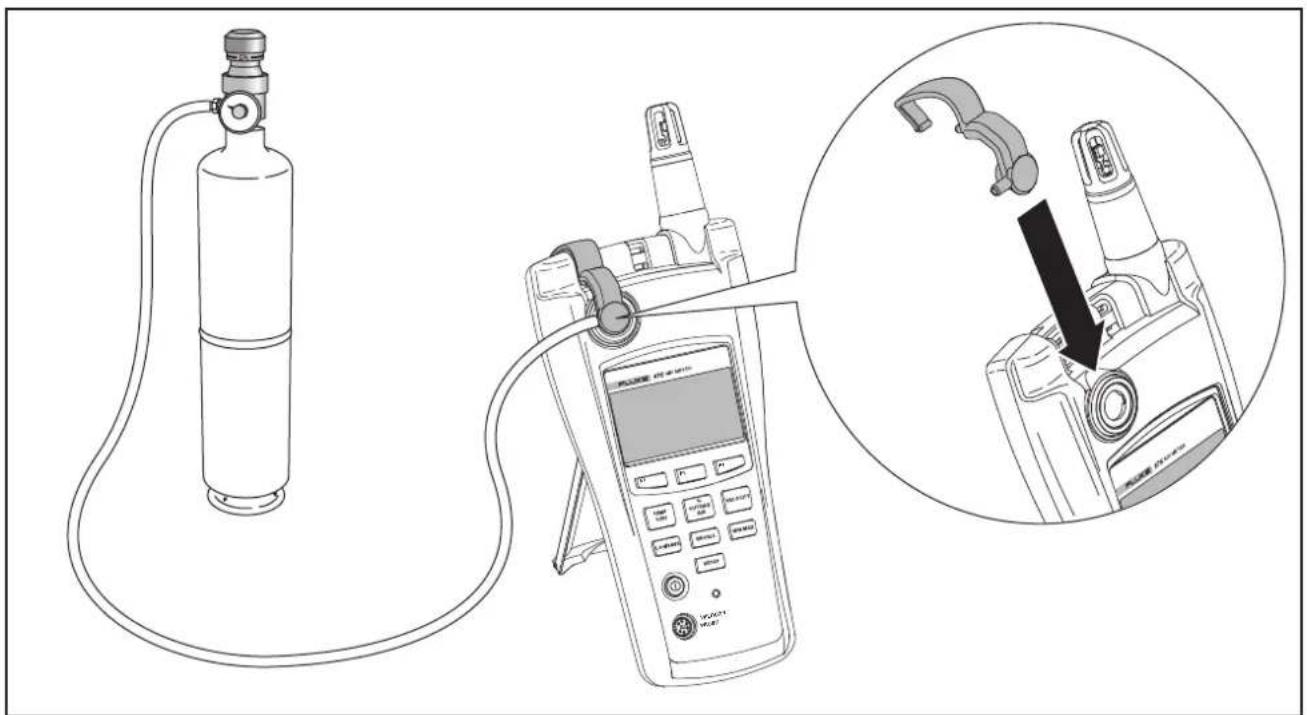
Figure 4. Calibration Set Up
eba09f.eps
Maintenance
Warning
The Meter contains no user-serviceable parts. To avoid electric shock, injury, or damage to the Meter, do not open the case. For service and rechargeable battery replacement, the Meter must be sent to Fluke. See “Contacting Fluke”.
Cleaning the Meter
Periodically wipe the case and holster with a damp cloth and mild detergent.
Caution
To avoid damaging the Meter, do not use abrasives or solvents to clean the Meter case.
Battery Maintenance and Battery Charge Indicators
The Meter normally uses a rechargeable battery but is equipped with three AA batteries for backup power. The following sections explain how to charge or change the batteries.
Battery charge indicators for both the rechargeable battery and the backup power supply appear on the display at start up. Use these indicators to assess the battery charge:
RC ■ AA – Rechargeable battery and backup batteries are fully charged.
When both the rechargeable battery and the backup supply are installed in the Meter, the battery indicators display as follows:
☐RC – After the startup period, the indicators disappear until the rechargeable battery reaches 25 % of charge capacity.
☐RC ☐AA – When the rechargeable battery reaches 10 % of charge capacity, both icons appear.
☐RC ☐AA – When the rechargeable battery reaches 0 % of charge capacity, the rechargeable battery icon flashes.
☐RC ☐AA – When the rechargeable battery reaches 0 % of charge capacity, and the backup supply reaches 25 % of charge capacity, both icons flash.
☐RC ☐AA – When the rechargeable battery reaches 0 % of charge capacity, and the backup supply reaches 10 % of charge capacity, both icons flash.
When the Meter's rechargeable battery and backup supply are at 0 % of charge capacity, the Meter displays the following message:
Battery Empty
System is
Shutting Down...
The Meter then shuts itself off.
The battery indicators act differently when the backup supply is not present.
When only the rechargeable battery is in use, the battery indicators display as follows:
- When the rechargeable battery is completely charged, the indicator shows only at startup.
- RC – Rechargeable battery charge is at 25 % of capacity.
- RC – Rechargeable battery charge is at 10 % of capacity (flashing).
Charging the Battery and Using the Power Adapter

Note
This Meter contains a rechargeable lithium battery that cannot be serviced by the user.
Do not mix this battery with the solid waste stream. Spent batteries should be disposed of by a qualified recycler or hazardous materials handler.
Contact your authorized Fluke Service Center for recycling information.
The ac adapter is used to recharge the battery as well as power the Meter. This feature allows the Meter to be used while the battery is charging. Allow 2 hours to fully recharge the battery.
To connect the ac adapter/charger, see Figure 3:
- Plug the charger into the dc jack on the base of the Meter.
- Using the correct adapter for your country, plug the ac adapter into an ac outlet.
Changing the AA Batteries
To change the AA batteries used for backup power. See Figure 5. To replace the lithium battery, return the Meter to Fluke. See "Contacting Fluke".
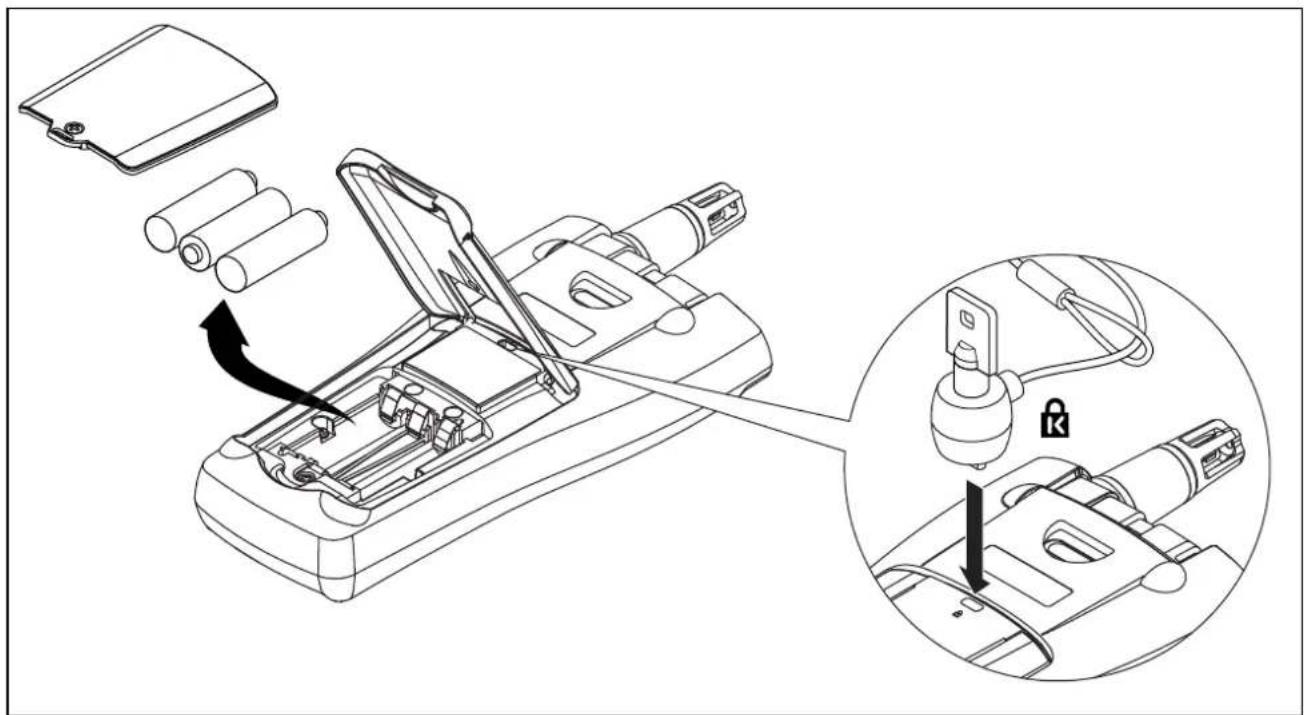
Figure 5. AA Battery Replacement and Kensington Lock Use
eba08f.eps
General Specifications
| Measured Parameters | Range | Display Resolution | Accuracy % of Reading |
| Temperature | -5 ° to 122 °F-20 ° to 50 °C | 0.1 °F0.1 °C | ±0.9 °C /±1.62 °F from 40 °C to 50 °C±0.5 °C /±1.00 °F from 5 °C to 40 °C±1.1 °C /±1.98 °F from -20 °C to 5 °C |
| Relative Humidity | 10 to 90 % R.H. non-condensing | 0.1 % | ±3 % RH from 10 % RH to 90 % RHIncludes 1 % hysteresis |
| Air Velocity | 50 to 3000 fpm0.25 to 15 m/sec | 1 fpm0.001 m/sec | ±4 % or 4 fpm*±4 % or .02 m/sec* whichever is greater* Accuracy specification only valid for velocity readings above 50 fpm or 0.25 m/sec. |
| CO2 0 to 5000 | ppm 1 ppm | Warm up time 1 min (5 minutes for full specification)2.75 % + 75 ppm | |
| CO 0 – 500 ppm | 1 ppm | ±5 % or ±3 ppm, whichever is greater,@ 20 °C and 50 %RHAdditional de-rating over Temperature:±0.6 %/°C from calibration temperature±0.6 %/°C < 20 °CLong term drift < 2 % per month.Maximum shift in arid or humid storage conditions*: ±0.6 % per day(Reference storage test conditions:50 °C, 15 % RH and 30 °C, 95 % RH) | |
| *After the CO calibration seal is removed and the Meter is stored for an extended period in arid or humid conditions, verify that the sensor is within specification by applying a known concentration of gas using the calibration procedures listed under Calibration. | |||
Calculated Parameters
| Calculated Parameters | Range | Display Resolution | Accuracy |
| Dew Point Temperature | -44 to 50 °C | 0.1 °C | ±1 °C WhenTemp: -20 °C to 50 °CRH: 40 % to 90 % |
| -47 to 122 °F | 0.1 °F | ±2 °C WhenTemp: -20 °C to 50 °CRH: 20 % to 40 % | |
| ±4 °C WhenRH: 10 % to 20 % | |||
| Wet Bulb Temperature | -16 to 50 °C | 0.1 °C | ±1.2 °C when :RH: 20 % to 90 %Temp: -20 °C to 50 °C |
| 3 to 122 °F | 0.1 °F | ±2.1 °C when :RH: 10 % to 20 % | |
| Volume Flow Rate (in a duct) | 1 cfm0.01 M3/hr | N/AThe volume flow calculation will be a simple average of the data points times the duct area | |
| % outside air (Based on Temperature) | 0 to 100 % 0.1 % | N/A | |
| % Outside Air (Based on CO2) | 0 to 100 % 0.1 % | N/A | |
| Minimum, Maximum and Average on all measured parameters | Per measured parameter spec | Per measured parameter spec Per measured parameter spec | |
Environmental Specifications
| Operating and Storage | |
| Temperature: | -20 to 50 °C (-4 to 122 °F) |
| Humidity: | 10 to 90 % non-condensing |
| Altitude: | Up to 2000 m (6562 ft) |
| Vibration: | Per MIL-PRF-28800F: Class 2 |
| Physical Specifications | |
| Meter size: | 28.70 cm x 11.43 cm x 5.08 cm (11.3 in x 4.5 in x 2 in) |
| Meter weight: | 0.544 kg (1.2 lb) |
| Hard-shell case size: | 11.93 cm x 35.65 cm x 43.18 cm (4.7 in x 14 in x 17 in) |
| Velocity probe size: | 28.70 cm, 99.06 cm extended x 2.54 cm (11.3 in, 39 in extended x 1 in) |
| Velocity probe weight: | 198 g (7 oz ) |
| Impact resistance: | 1 m drop test (3.28 ft drop test) |
| Power supply: | Rechargeable Lithium battery or Universal AC power adapter with plug adapters for USA, Great Britain, Europe, and Australia |
| Backup power supply: | 3 AA (IEC LR06) batteries used as backup power |
| Battery life: | Rechargeable Lithium battery - 11 hours (at room temperature)* |
| Backup AA batteries - 7 hours | |
*Note
Lithium batteries can greatly extend the operating life of the meter if cared for properly. To ensure optimum capacity do not store for extended periods of time above 35 ^ ( 95 ^ ).
Agency Approvals, Certifications and Standards Compliance
The Meter complies with the following standards and meets requirements for the following certifications:
EMC: EN61326-1.
AS/NSZ CISPR 11
Safety: EN61010:2001

N10140

Replaceable Parts and Accessories
To order parts and accessories for the Meter, refer to Figure 6 and Table 6.
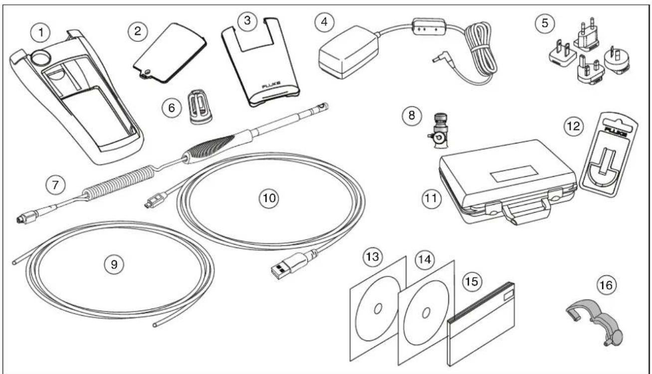
Figure 6. Replaceable Parts and Accessories
eba10f.eps
Table 6. Replaceable Parts and Accessories
| Item Number | Part Number or Model Number | Description |
| 1 251 | 4351 Holster | |
| 2 251 | 4336 Battery Door | |
| 3 251 | 4349 Tilt Stand | |
| 4 266 | 4162 AC Power Adapter | |
| 5 266 | 4357 | International Adapter Blade Kit containing type A, C, G, and I adapters to fit most countries |
| 6 252 | 6937 Cap, Temperature/Humidity Probe | |
| 7 Air | Velocity Probe Air Velocity Probe (optional) | |
| 8 277 | 0767 Calibration-flow regulator valve | |
| 9 267 | 9599 Calibration tubing, Plastic 2 ft x 1⁄4 inch | |
| 10 266 | 5668 USB Cable | |
| 11 267 | 9501 Hard Shell Carrying Case | |
| 12 TPAK80-4 ToolPak accessory kit (optional) | ||
| 13 157 | 8384 FlukeView ® Forms Documenting Software | |
| 14 250 | 7224 | 975 Manuals CD containing the Users Manuals in English, French, German, Portuguese, Spanish, and Simplified Chinese |
| 15 250 | 7213 Users Manual (printed English) | |
| 16 269 | 4684 Calibration Cap | |
- LIMITED WARRANTY AND LIMITATION OF LIABILITY
- Table of Contents
- Title
- Page
- Contents
- List of Tables
- Table Title Page
- List of Figures
- Figure Title Page
- Introduction
- ⚠ Warning
- Read "Safety Information" before using the 975 AirMeter™ Test Tool.
- Features
- Contacting Fluke
- Safety Information
- Warning
- Caution
- Symbols
- Shipping Contents
- Using the Meter
- Softkeys and Pushbuttons
- Meter Power
- Note
- Startup and Self Test
- Automatic Backlight
- Automatic Power Off
- Multi-Language Interface
- Measurement Units
- Time and Date Stamp
- CO Alarm
- The Setup Menu
- Taking Measurements
- Temperature, Relative Humidity, CO, CO₂, Dew Point, and Wet Bulb Measurements
- % Outside Air
- % Outside Air (Temperature)
- % Outside Air (CO₂)
- Air Velocity and Volume Flow Rate
- Standard Velocity and Actual Velocity
- Velocity Probe
- Measuring Air Velocity
- Measuring Volume Flow Rate
- Min Max Avg
- Data Logging
- Saving Single-Point Data
- Continuous Data Logging
- Notes
- Logging Button Lockout
- Recalling or Erasing Logged Data
- Transferring Data to a Personal Computer
- Calibration
- Calibrating the CO and CO_2 Sensors
- Calibrating the CO Sensor
- Calibrating the CO₂ Sensor
- Maintenance
- Cleaning the Meter
- Battery Maintenance and Battery Charge Indicators
- Battery Empty
- System is
- Shutting Down...
- Charging the Battery and Using the Power Adapter
- Changing the AA Batteries
- Agency Approvals, Certifications and Standards Compliance
- Replaceable Parts and Accessories
Brand : FLUKE
Model : 975
Category : Uncategorized