AVO-VGA - Switch Intelix - Free user manual and instructions
Find the device manual for free AVO-VGA Intelix in PDF.


| Product Type | VGA Switch |
| Model | AVO-VGA |
| Brand | Intelix |
| Number of Inputs | 4 |
| Number of Outputs | 1 |
| Supported Resolution | Up to 1920x1200 @60Hz |
| Video Bandwidth | 350 MHz |
| Connector Type | VGA (DB-15) Female |
| Power Supply | 5V DC via USB or optional adapter |
| Power Consumption | 0.5 W |
| Dimensions (L x W x H) | 100 x 60 x 25 mm |
| Weight | 85 g |
| Enclosure Material | Metal |
| Operating Temperature | 0°C to 50°C |
| Storage Temperature | -20°C to 60°C |
| Humidity | 10% to 85% RH non-condensing |
| Switch Type | Manual push-button or auto-switching |
| Compatible Systems | VGA sources (PC, laptop, DVD, etc.) and displays |
| Maintenance | Wipe with dry cloth; no internal cleaning required |
| Safety | Use only with approved power source; keep away from moisture |
| Spare Parts | Replacement power adapter (5V DC), VGA cables |
| Repairability | Not user-serviceable; contact professional for repairs |
Frequently Asked Questions - AVO-VGA Intelix
User questions about AVO-VGA Intelix
0 question about this device. Answer the ones you know or ask your own.
Ask a new question about this device
Download the instructions for your Switch in PDF format for free! Find your manual AVO-VGA - Intelix and take your electronic device back in hand. On this page are published all the documents necessary for the use of your device. AVO-VGA by Intelix.
USER MANUAL AVO-VGA Intelix
The Intelix AVO-VGA balun set transmits VGA video passively over standard unshielded twisted pair cable, such as Cat 5, Cat 5e or Cat 6. The AVO-VGA eliminates costly and bulky VGA cable, and extends video transmission distances.
Pre-Installation
Note: The AVO-VGA does not support VGA handshaking and control signals. Therefore, it is necessary to set the monitor attributes prior to installing the balun set. First connect the source (typically a computer) directly to the destination (typically a monitor) with a standard VGA cable. After doing so, set the monitor attributes to the required settings (i.e., resolution, color, etc.). For best results, also set the contrast and brightness to the maximum level.
The AVO-VGA features shielded RJ45 connectors, which are provided as an option in harsh electrical environments, such as installations with large motors or cable runs near sources of interference. In such environments, shielded twisted pair cable (STP) may provide additional noise immunity. When using STP, ensure the shield on both ends of the cable run is terminated to a shielded RJ45 connector.
Caution: Do not attempt to disassemble or alter the balun housing. There are no user-serviceable parts inside the unit. Doing so will void your warranty.
Installation
- Power off the source and destination devices which will be connected to the baluns.
- Verify the modular outlets and cross connects to which you will connect the AVO-VGA are configured properly and labeled appropriately to identify the circuit.
Caution: To minimize the possibility of equipment damage from electrostatic discharge (ESD), all source and destination equipment must be powered off during installation. This includes signal extenders, splitters, and switches.
- Verify the desired twisted pairs are not being used for other LAN or telephone equipment.
Caution: Do not connect the balun to a telecommunication outlet wired to unrelated equipment. Doing so may damage the unit or any connected equipment. Ensure all connected twisted pair cabling is straight-through (point-to-point).
- Connect the send balun (AVO-VGA-S) to the VGA port of the source equipment. Tighten the mounting screws on each balun.
- Connect one end of the twisted pair cable to the send balun. The RJ45 pinout in the twisted pair cabling should conform to the EIA/TIA 568A or 568B standard.
- Connect the receive balun (AVO-VGA-R) to the destination equipment.
- Connect the other end of the twisted pair cable to the receive balun. The RJ45 pinout in the twisted pair cabling should conform to the EIA/TIA 568A or 568B standard.
Note: For your convenience, it is recommended that you uniquely mark the ends of the twisted pair cable before pulling them through a wall or conduit.
- Power on the source and destination equipment.
- If necessary, set monitor contrast and brightness to the desired levels.
- Set the monitor refresh rate to the optimal rate for the display at the desired resolution.
- If necessary, adjust the image quality with the Sync Adjust switch on the send and receive baluns. It is recommended that both switches be in the same position.
Note: The AVO-VGA features an optional grounding screw that may be used to correct any image anomalies, such as differences in hue from one side of a monitor to the next. Should this occur, connect the balun ground to earth ground. However, if the building has a grounding problem, such as ground loops, grounding the balun may negatively affect the signal. Only ground the AVO-VGA if it positively affects the signal.
Troubleshooting
| Symptom | Probable | Causes Possible Solut |
| Image distorted or skewed | Weak or distorted sync signal | Change the screen refresh rate of the video source to the next higher or lower setting |
| Adjust the Sync Adjust switch on both the send and receive baluns | ||
| No image | Attach or detach the grounding screw on either or both of the baluns to earth ground | |
| Reversed polarity Unus | Verify RJ45 pinout conforms to EIA/TIA 568A or 568B standard. If not, re-crimp the cable. | |
| Bad RJ45 crimp | ||
| Smearing or weak video contrast | Exceeded cable distance | Verify cable grade and total cabling distance |
| Reduce the screen resolution | ||
| Reduce the screen refresh rate | ||
| Horizontal bars moving upward in background | Ground loop problem | Attach or detach the grounding screw on either or both of the baluns to earth ground |
| Verify the source and destination equipment are at the same ground potential. | ||
| Shaking image | Change the screen refresh rate of the video source to the next higher or lower setting | |
| Background pattern | EMI interference | Identify possible radiating frequency sources and isolate them from the cabling. Use shielded twisted pair cabling. |
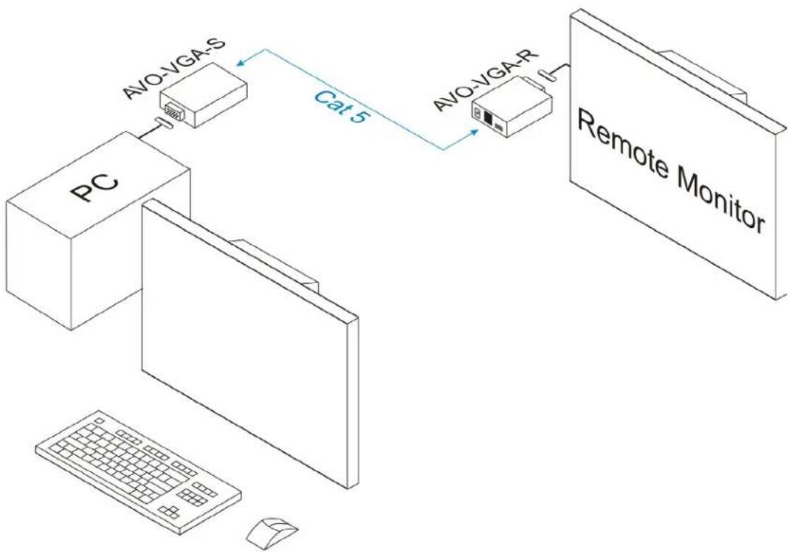
flowchart
graph TD
    PC["PC"] -->|AVO-VGA-S| AVO_S["AVO-VGA-S"]
    AVO_S -->|Cat 5| AVO_R["AVO-VGA-R"]
    AVO_R --> Remote_Monitor["Remote Monitor"]
Technical Specifications
| Environment | VGA. VESA VP&D 1.0, VIP ver 2.0 |
| Devices | CRT/LCD monitors, plasmas, laptops, PCs, projectors |
| Bandwidth | DC to 60 MHz |
| Input Signals | Video: 1.1 Vp-pH/VSync: TTL standard; 300 kHz max bandwidth |
| Insertion Loss | Less than 3 dB per pair over the frequency range |
| Return Loss | -15 dB max from DC to 60 MHz |
| Max. Distance via Cat 5 | VGA: 640 x 480 pixels (14 MHz) 450ft (137m)SVGA: 800 x 600 pixels (22 MHz) 350ft (107m)XGA: 1024 x 768 pixels (35 MHz) 250ft (76m)SXGA: 1280 x 1024 pixels (59 MHz) 200ft (61m) |
| RJ45 Pin ConfigurationReverse Polarity Sensitive | Pins 4 and 5 Green (balanced)Pins 1 and 2 Red (balanced)Pins 7 and 8 Blue (balanced)Pins 3 and 6 Horizontal and Vertical Sync (unbalanced) |
| Cable | Unshielded Cat 5, Cat 5e, Cat 6 or better |
| Temperature | Operating: 0 to 55 C.Storage: -20 to 85 C.Humidity: up to 95% non-condensing |
| Warranty | 2 years |
| Order Information | AVO-VGA: one send and one receive balunAVO-VGA-R: one receive balunAVO-VGA-S: one send balun |
Distances and picture quality may be affected by cable grade, cable quality, source and destination equipment, RF and electrical interference, and cable patches. Intelix specifications are based on straight-through cabling with standard-grade Cat 5.
Intelix
2222 Pleasant View Road
Middleton, WI 53562
608-831-0880 | phone
866-4-MATMIX | toll-free
608-831-1833 | fax
www.intelix.com
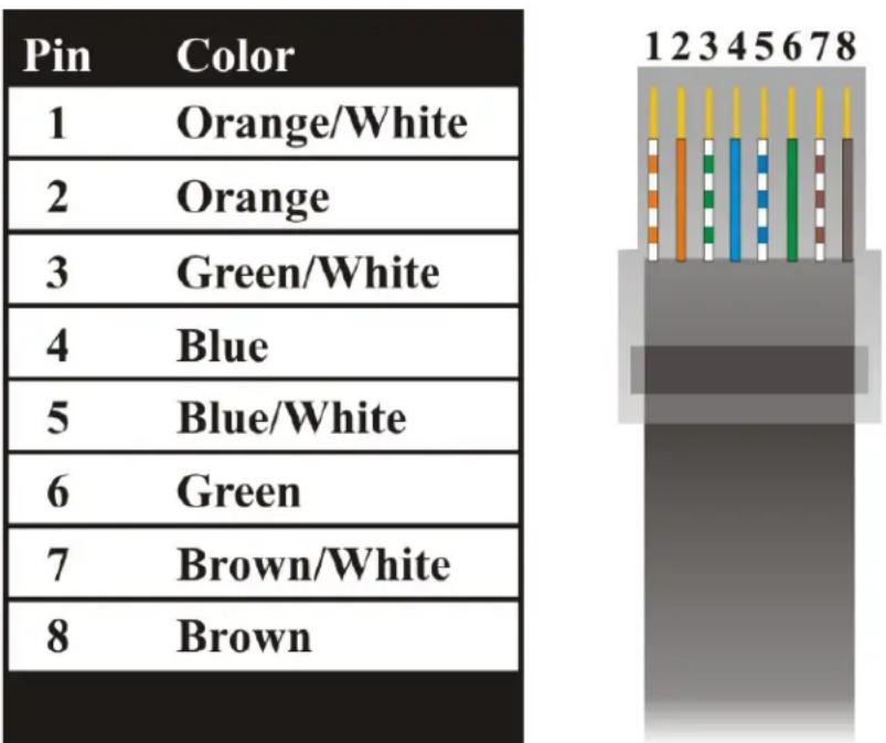
EIA/TIA 568B Crimp Pattern Standard
Brand : Intelix
Model : AVO-VGA
Category : Switch