
DS-A82024D - Server Hikvision - Free user manual and instructions
Find the device manual for free DS-A82024D Hikvision in PDF.


| Type de produit | Serveur de stockage / Enregistreur vidéo réseau (NVR) |
| Marque | Hikvision |
| Modèle | DS-A82024D |
| Format | 2U Rackmount |
| Dimensions (L x P x H) | 430 mm x 660 mm x 88.4 mm |
| Poids | Environ 20 kg (sans disques) |
| Alimentation | Double alimentation redondante 100-240 V AC, 50/60 Hz |
| Baies de disques | 24 baies (SATA/SAS, 3.5 pouces) |
| Capacité maximale | 192 To (24 x 8 To) |
| RAID pris en charge | RAID 0, 1, 5, 6, 10, JBOD |
| Processeur | Processeur Intel Xeon (génération selon version) |
| Mémoire vive (RAM) | 16 Go DDR4, extensible jusqu'à 128 Go |
| Interfaces réseau | 2 x Gigabit Ethernet RJ45, 2 x 10 Gigabit SFP+ |
| Fonctions principales | Enregistrement vidéo, stockage centralisé, gestion RAID, sauvegarde, analyse vidéo |
| Système d'exploitation | Hikvision Embedded Linux / Windows Server (selon version) |
| Entretien et nettoyage | Dépoussiérer régulièrement, remplacer les filtres à air tous les 6 mois, vérifier la ventilation |
| Sécurité | Mise à la terre, environnement tempéré (10-35°C), humidité 8-80% sans condensation |
| Pièces détachées et réparabilité | Alimentation, ventilateurs, disques durs, carte mère (standard Hikvision) |
| Informations générales | Conçu pour les systèmes de vidéosurveillance IP, compatible avec les caméras Hikvision |
Frequently Asked Questions - DS-A82024D Hikvision
User questions about DS-A82024D Hikvision
0 question about this device. Answer the ones you know or ask your own.
Ask a new question about this device
Download the instructions for your Server in PDF format for free! Find your manual DS-A82024D - Hikvision and take your electronic device back in hand. On this page are published all the documents necessary for the use of your device. DS-A82024D by Hikvision.
USER MANUAL DS-A82024D Hikvision
natural_image
Abstract geometric composition with gray and red diamond shapes (no text or symbols)
natural_image
Red background with white globe and hand symbol (no text or numbers)Storage System UserManual
Legal Information
About this Document
- This Document includes instructions for using and managing the Product. Pictures, charts, images and all other information hereinafter are for description and explanation only.
- The information contained in the Document is subject to change, without notice, due to firmware updates or other reasons. Please find the latest version of the Document at the Hikvision website (https://www.hikvision.com). Unless otherwise agreed, Hangzhou Hikvision Digital Technology Co., Ltd. or its affiliates (hereinafter referred to as "Hikvision") makes no warranties, express or implied.
- Please use the Document with the guidance and assistance of professionals trained in supporting the Product.
About this Product
- This product can only enjoy the after-sales service support in the country or region where the purchase is made.
- If the product you choose is a video product, please scan the following QR code to obtain the "Initiatives on the Use of Video Products", and read it carefully.

Acknowledgment of Intellectual Property Rights
- Hikvision owns the copyrights and/or patents related to the technology embodied in the Products described in this Document, which may include licenses obtained from third parties.
- Any part of the Document, including text, pictures, graphics, etc., belongs to Hikvision. No part of this Document may be excerpted, copied, translated, or modified in whole or in part by any means without written permission.
- HIKVISION and other Hikvision's trademarks and logos are the properties of Hikvision in various jurisdictions.
- Other trademarks and logos mentioned are the properties of their respective owners.
- HDMI™ The terms HDMI and HDMI High-Definition Multimedia Interface, and the HDMI Logo are trademarks or registered trademarks of HDMI Licensing Administrator, Inc. in the United States and other countries.
LEGAL DISCLAIMER
- TO THE MAXIMUM EXTENT PERMITTED BY APPLICABLE LAW, THIS DOCUMENT AND THE PRODUCT DESCRIBED, WITH ITS HARDWARE, SOFTWARE AND FIRMWARE, ARE PROVIDED "AS IS" AND "WITH ALL FAULTS AND ERRORS". HIKVISION MAKES NO WARRANTIES, EXPRESS OR IMPLIED, INCLUDING WITHOUT LIMITATION, MERCHANTABILITY, SATISFACTORY QUALITY, OR FITNESS FOR A PARTICULAR PURPOSE. THE USE OF THE PRODUCT BY YOU IS AT YOUR OWN RISK. IN NO EVENT WILL HIKVISION BE LIABLE TO YOU FOR ANY SPECIAL, CONSEQUENTIAL, INCIDENTAL, OR INDIRECT DAMAGES, INCLUDING, AMONG OTHERS, DAMAGES FOR LOSS OF BUSINESS PROFITS, BUSINESS INTERRUPTION, OR LOSS OF DATA, CORRUPTION OF SYSTEMS, OR LOSS OF DOCUMENTATION, WHETHER BASED ON BREACH OF CONTRACT, TORT (INCLUDING NEGLIGENCE), PRODUCT LIABILITY, OR OTHERWISE, IN CONNECTION WITH THE USE OF THE PRODUCT, EVEN IF HIKVISION HAS BEEN ADVISED OF THE POSSIBILITY OF SUCH DAMAGES OR LOSS.
- YOU ACKNOWLEDGE THAT THE NATURE OF THE INTERNET PROVIDES FOR INHERENT SECURITY RISKS, AND HIKVISION SHALL NOT TAKE ANY RESPONSIBILITIES FOR ABNORMAL OPERATION, PRIVACY LEAKAGE OR OTHER DAMAGES RESULTING FROM CYBER-ATTACK, HACKER ATTACK, VIRUS INFECTION, OR OTHER INTERNET SECURITY RISKS; HOWEVER, HIKVISION WILL PROVIDE TIMELY TECHNICAL SUPPORT IF REQUIRED.
- YOU AGREE TO USE THIS PRODUCT IN COMPLIANCE WITH ALL APPLICABLE LAWS, AND YOU ARE SOLELY RESPONSIBLE FOR ENSURING THAT YOUR USE CONFORMS TO THE APPLICABLE LAW. ESPECIALLY, YOU ARE RESPONSIBLE, FOR USING THIS PRODUCT IN A MANNER THAT DOES NOT INFRINGE ON THE RIGHTS OF THIRD PARTIES, INCLUDING WITHOUT LIMITATION, RIGHTS OF PUBLICITY, INTELLECTUAL PROPERTY RIGHTS, OR DATA PROTECTION AND OTHER PRIVACY RIGHTS. YOU SHALL NOT USE THIS PRODUCT FOR ANY PROHIBITED END-USES, INCLUDING THE DEVELOPMENT OR PRODUCTION OF WEAPONS OF MASS DESTRUCTION, THE DEVELOPMENT OR PRODUCTION OF CHEMICAL OR BIOLOGICAL WEAPONS, ANY ACTIVITIES IN THE CONTEXT RELATED TO ANY NUCLEAR EXPLOSIVE OR UNSAFE NUCLEAR FUEL-CYCLE, OR IN SUPPORT OF HUMAN RIGHTS ABUSES.
- IN THE EVENT OF ANY CONFLICTS BETWEEN THIS DOCUMENT AND THE APPLICABLE LAW, THE LATTER PREVAILS.
© Hangzhou Hikvision Digital Technology Co., Ltd. All rights reserved.
RegulatoryInformation
FCCInformation
FCCcompliance: This equipment has been tested and found to comply with the limits for a Class A digital device, pursuant to part 15 of the FCC Rules. These limits are designed to provide reasonable protection against harmful interference when the equipment is operated in a commercial environment. This equipment generates, uses, and can radiate radio frequency energy and, if not installed and used in accordance with the instruction manual, may cause harmful interference to radio communications. Operation of this equipment in a residential area is likely to cause harmful interference in which case the user will be required to correct the interference at his own expense. The device is advised to note that as a seller or a business user (Class A) Devices and intended for use outside the Home area.
FCC Conditions
This device complies with part 15 of the FCC Rules. Operation is subject to the following two conditions:
- This device may not cause harmful interference.
- This device must accept any interference received, including interference that may cause undesired operation.
EU Conformity Statement

This product and - if applicable - the supplied accessories too are marked with "CE" and comply therefore with the applicable harmonized European standards listed under the EMC Directive
2014/30/EU, the RoHS Directive 2011/65/EU, the LVD Directive 2014/35/EU.

2012/19/EU (WEEE directive): Products marked with this symbol cannot be disposed of as unsorted municipal waste in the European Union. For proper recycling, return this product to your local supplier upon the purchase of equivalent new equipment, or dispose of it at designated collection
points. For more information see: www.recyclethis.info

2006/66/EC (battery directive): This product contains a battery that cannot be disposed of as unsorted municipal waste in the European Union. See the product documentation for specific battery information. The battery is marked with this symbol, which may include lettering to indicate
cadmium (Cd), lead (Pb), or mercury (Hg). For proper recycling, return the battery to your supplier or to a designated collection point. For more information see: www.recyclethis.info
Industry Canada ICES-003 Compliance
This device meets the CAN ICES-3 (A)/NMB-3(A) standards requirements.
SafetyInstruction
These instructions are intended to ensure that user can use the product correctly to avoid danger or property loss.
The precaution measure is divided into "Warnings" and "Cautions"
Warnings: Serious injury or death may occur if any of the warnings are neglected.
Cautions: Injury or equipment damage may occur if any of the cautions are neglected.
| Warnings Follow these safeguards to prevent serious injury or death. | CautionsFollow these precautions to prevent potential injury or material damage. |

Warnings
- Proper configuration of all passwords and other security settings is the responsibility of the installer and/or end-user.
- In the use of the product, you must be in strict compliance with the electrical safety regulations of the nation and region. Please refer to technical specifications for detailed information.
- Input voltage should meet both the SELV (Safety Extra Low Voltage) and the Limited Power Source with 100\~240 VAC or 12 VDC according to the IEC60950-1 standard. Please refer to technical specifications for detailed information.
- Do not connect several devices to one power adapter as adapter overload may cause over-heating or a fire hazard.
- Please make sure that the plug is firmly connected to the power socket.
- If smoke, odor or noise rise from the device, turn off the power at once and unplug the power cable, and then please contact the service center.
Table of Contents
Chapter 1 Overview....7
Chapter 2 Getting Started....8
2.1 HDD Installation....9
2.2 Accessing by Web Browser 10
2.3 Login 11
Chapter 3 Maintenance....12
3.1 System 13
3.2 Performance 13
3.3 General 15
3.3.1 Viewing Version Information 15
3.3.2 Default Settings 16
3.3.3 Managing Maintenance Log 16
3.3.4 Modifying Password....16
3.3.5 SNMP Configuration 17
3.3.6 Modifying Host Name 17
3.3.7 Viewing Service Status 18
3.3.8 System Upgrade 18
3.4 Graphical Display 19
3.4.1 Front View 19
3.4.2 Pie Chart 20
3.5 Environmental 20
Chapter 4 StorageManagement....22
4.1 Managing Local HDD 23
4.1.1 Viewing HDD Status 23
4.1.2 Rescanning HDD 24
4.1.3 Positioning HDD 24
4.1.4 HDD Initialization 25
4.1.5 HDD Detection 25
4.2 Array 26
4.2.1 Creating Array 26
4.2.2 Array Exception 28
4.2.3 Rebuilding Array 28
4.2.4 Detecting Array 29
4.2.5 Repairing Array 29
4.2.6 Renaming Array 29
4.2.7 Deleting Array 30
4.2.8 Adding Hot Spare 30
4.2.9 Deleting Hot Spare 31
4.3 Storage Pool....31
4.3.1 Adding Storage Pool 32
4.3.2 Deleting Storage Pool 33
4.3.3 Positioning Storage Pool 33
4.4 Logical Volume 33
4.4.1 Creating Logical Volume 34
4.4.2 Deleting Logical Volume 34
4.4.3 Renaming Logical Volume 34
4.4.4 Enlarging Logical Volume 35
4.5 Configuration 35
4.5.1 Synchronization Speed and Type 36
4.5.2 Flickering Time 36
Chapter 5 SAN....37
5.1 iSCSI 38
5.1.1 Adding CHAP User 38
5.1.2 Modifying CHAP User 38
5.1.3 Enabling iSCSI 39
5.1.4 Disabling iSCSI 40
5.1.5 Modifying iSCSI Port 40
5.2 FC (Optional) 40
5.2.1 Enabling FC 41
5.2.2 Disabling FC 42
Chapter 6 HYBRIDSAN....43
6.1 One-Key Configuration 44
6.2 HYBRID SAN Configuration 44
6.2.1 Starting HYBRID SAN 45
6.2.2 Resetting HYBRID SAN 47
6.2.3 Record Volume 48
6.3 Backup and Restoring 50
6.3.1 Viewing Private Volume Information 50
6.3.2 Restoring 51
6.3.3 Backup 51
6.3.4 Recovering Video Data 52
6.4 N+1 Management 53
6.4.1 Adding Backup HYBRID SAN 53
6.4.2 Deleting Backup HYBRID SAN 54
6.4.3 Adding Master HYBRID SAN 54
Chapter 7 HYBRIDSAN Sub-System....56
7.1 Access by Web Browser ....57
7.2 Information....57
7.3 Encoding Device 58
7.3.2 Adding Encoding Device 58
7.3.3 Modifying and Deleting ....59
7.3.4 Exporting and Importing Encoding Device 60
7.4 Previewing and Recording 61
7.5 Strategy and Alarm 62
7.5.1 Record Plan 62
7.5.2 Upload Strategy....65
7.5.3 Alarm 67
7.6 Playing and Downloading 69
7.6.1 Searching Video 69
7.6.2 Locking Videos 69
7.6.3 Playing Videos....70
7.6.4 Downloading Videos 72
7.7 User 74
7.8 System Configuration....74
7.8.1 System Alarm 74
7.8.2 HYBRID SAN Version 75
7.9 Log Management 76
7.9.1 Searching Log 76
7.9.2 Exporting Log 77
7.9.3 Clearing Log 77
Chapter 8 System....78
8.1 Network....79
8.1.1 Modifying Data Network Interface 79
8.1.2 Binding Network Interfaces 79
8.1.3 Adding Route 80
8.1.4 MAC and IP Bonding 81
8.1.5 Advanced Parameters 81
8.2 Alarm 84
8.2.1 Alarm Type 84
8.2.2 Adding Email 86
8.2.3 Testing Email 87
8.2.4 Adding SNMP Manager 87
8.2.5 Testing SMTP Manager 88
8.3 Time 88
8.3.1 Adjusting System Time 88
8.3.2 Synchronizing Time 89
Chapter 9 Log....90
9.1 Operation Log 91
9.2 Performance Log....91
9.3 Upgrade Log 92
Chapter 1 Overview
Purpose:
DS-A80&81 series storage system is a high-performance and highly reliable storage system. Designed with four enterprise-class gigabyte network interfaces, it provides a bandwidth with 4 to 8G bps transmission capability and a huge storage space. It is integrated with multiple advanced technologies, including a 64-bit hexa-core processors, stable architecture, and the RAID 6 storage technology, thus to run reliably and protect user data security effectively.
Figure 1. 1 GUI and Table 1. 1 GUI Introduction introduce the elements appear in the GUI (Graphical User Interface) and clarify names for each element.
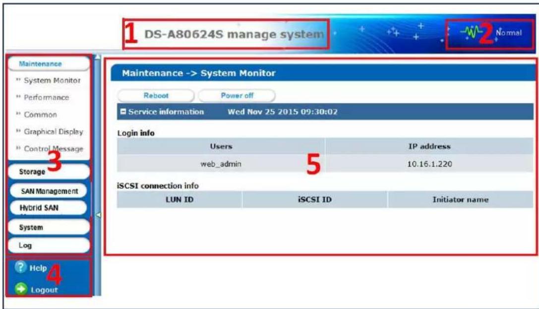
Figure 1.1 GUI
Table 1.1 GUI Introduction
| No. | Name | Description |
| 1 | Banner and device model | Shows the device model. |
| 2 | Running status | A shortcut for obtaining the real-time running status. |
| 3 | Navigation Bar | Lists the storage system menu. |
| 4 | Help and logout | A shortcut for accessing user manuals, downloading software, and logout. |
| 5 | Operation window | Lists the parameters. You can configure parameters in the area. |
Chapter 2 Getting Started
Purpose:
The chapter introduces HDD installation steps, web browser access steps, and login steps.
Table 2.1 Module Description
| Module Description | |
| HDD Installation | Describes the steps of HDD installation. |
| Web Browser Access | You can get access to the storage system via a server with the web browser installed. |
| Login Introduces login | storage system steps. |
Key Words:
HDD Installation, Web Browser Access, Login
2.1 HDDInstallation

In the event of device appearance shown in following steps conflicts with real device, the later prevails.
Beforeyou start:
Prepare the following equipment and accessories.
- A storage system
- Hard HDDs
● A pair of anti-static gloves - A screwdriver
Steps:
- Press the blue button. Then the handle pops up.
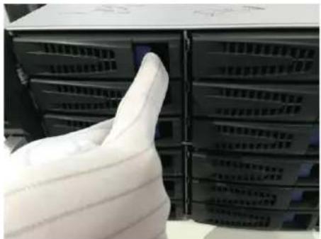
natural_image
Close-up of a hand inserting a white plastic bag into a rack of black server racks (no visible text or symbols)Figure 2.2 Press the Blue Button
- Hold the hander and pull the HDD dummy out of the slot.
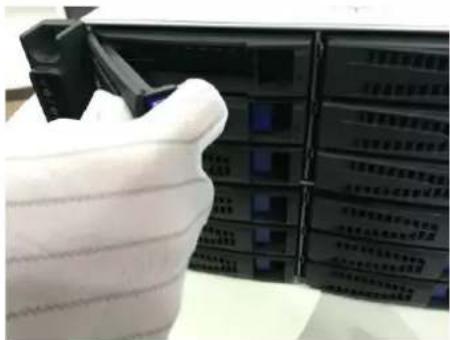
natural_image
Close-up of a white hard hat partially covered by a black server rack, with no visible text or symbols on the rack or background.Figure 2.3 Pull out the HDD Dummy
- Use the screwdriver to uninstall the baffle in the bottom of HDD slot.
- Place an HDD in the HDD dummy. The SATA interface must face the HDD dummy rear.
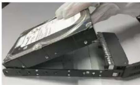
natural_image
Close-up of a hand holding a hard disk drive into a rack, showing internal components and mounting holes (no text or symbols visible)Figure 2. 4 Place HDD
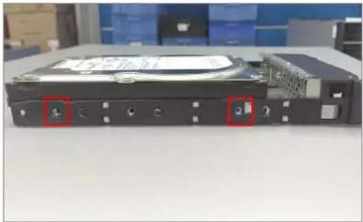
- Adjust the HDD position. Ensure the HDD rear aligning with HDD dummy rear and the two screw holes aiming at the holes that marked with red frame in Figure 2.5 HDDPosition.
natural_image
Exterior view of a hard disk drive chassis with two red-labeled buttons on the rear panel (no visible text or symbols)Figure 2.5 HDD Position
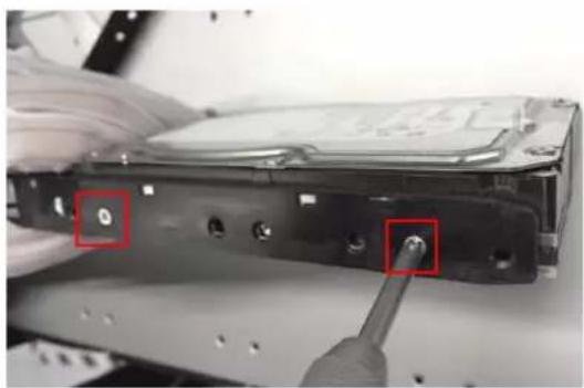
- Use a screwdriver to fasten the four screws into the screw holes in both sides.
natural_image
Close-up of hands operating a hard disk drive with a screwdriver inserted (no visible text or symbols)Figure 2.6 Install Screws
- Push the HDD dummy back into the slot.
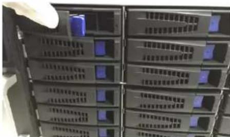
Figure 2.7 Push the HDD Dummy into Slot
2.2 Accessingby Web Browser

You shall acknowledge that the use of the product with Internet access might be under network security risks. For avoidance of any network attacks and information leakage, please strengthen your own protection. If the product does not work properly, please contact with your dealer or the nearest service center.
Purpose:
You can get access to the storage system via a server with a web browser installed, without needing to install any other software. The recommended web browsers are Internet Explorer 8 and Internet Explorer 11.
Beforeyou start:
- Use a network cable to connect the system Ethernet port and the storage system management network interface.
- Configure the server IP address. Ensure it is in the same network segment with the IP address of management network interface is 10.254.254.254.
Steps:
- Open web browser.
- Input the storage system IP address (https://10.254.254.254:2004) in Web browser address bar.
- Press Enter.
2.3 Login
Steps:
- If the device has not been activated, you need to activate the device first before login.
- Set the password for the admin user account.
- Click OK to login to the device.

STRONGPASSWORDRECOMMENDED—Wehighly recommend you create a strong password of your own choosing (Using a minimum of 8 characters, including at least three of the following categories: upper case letters, lower case letters, numbers, and special characters.) in order to increase the security of your product. And we recommend you reset your password regularly, especially in the high security system, resetting the password monthly or weekly can better protect your product.
● If the device is already activated:
- Select Login account as Basic Management or HYBRIDSAN Sub-system.
BasicManagement: Used to configure basic parameters of the storage system.
HYBRIDSAN Sub-system: Used to Log into the HYBRID SAN sub-system.
- Select Username.
- Enter Password.
- Mode is Advanced by default and is not selectable.
- Click Loginto log in the system.
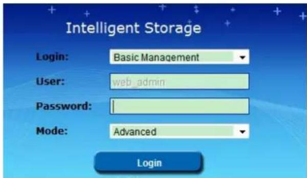
Figure 2.8 Login
Chapter 3 Maintenance
Purpose:
Maintenance function enables you to view login and iSCSI information, monitor running status, restore default settings, check and download logs, upgrade storage system, and so forth.
Table 3.1 Module Description
| Module Description | |
| System | ● A shortcut for reboot and shutdown.● Lists the login user information and iSCSI connection information. |
| Performance | Shows you the real-time graph and data of system performance, including bandwidth usage, memory usage, CPU usage, IO status, and Vmstatus. |
| General | You can view system version, reset system, view logs, upgrade system, and add check and repair strategy. |
| Graphical Display | Provides a graph to show the front view status and a pie chart to show the storage information. |
| Environmental | Shows the fan information, module temperature, fan control panel version, and chassis power. |
Keywords:
System, Performance, General, Graphical Display, Environmental
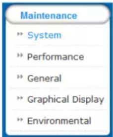
Figure 3.2 Maintenance
3.1 System
Purpose:
Once you log into the storage system, system menu appears. System menu is a shortcut for reboot and shutdown and lists the login users and iSCSI connection information.
Steps:
- Click Maintenance in navigation bar and choose Systemto enter System interface.
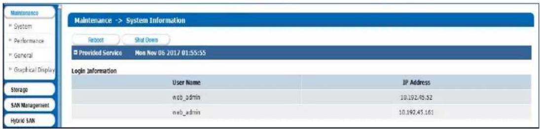
Figure 3. 3 System Monitor
-
Reboot, power off, or view login information or iSCSI connection info.
-
Click Rebootor Poweroff to restart or shut down the storage system.
• The logged in users and IPaddresses are listed in the Logininfo. - The LUN ID, iSCSIID, and Initiator name are listed in iSCSI connection info, which shows which devices are connecting iSCSI.
3.2 Performance
Purpose:
Performance menu shows you the real-time graph and data of system performance, including bandwidth usage, memory usage, CPU usage, IO status, and system performance.
Steps:
- Click Maintenance in navigation bar and choose Performanceto enter Performance interface.
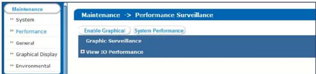
Figure 3.4 Performance
- Click EnableGraphicalto show the real-time graphs of bandwidth usage, memory usage, and CPU usage.
- Optionally, click DisableGraphicalto fold the graphs.
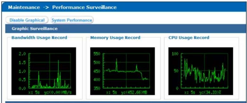
Figure 3.5 Graph Monitor
- Click System Performance to pop up system performance window. System performance updates per second.
- Click + of View IPPerformanceto unfold input/output status.
- Optionally, click ☐ of View IPPerformance to fold input/output status.
3.3 General
Purpose:
You can view system version, reset system, view logs, and upgrade system.
Step:
Click Maintenance in navigation bar and choose General.
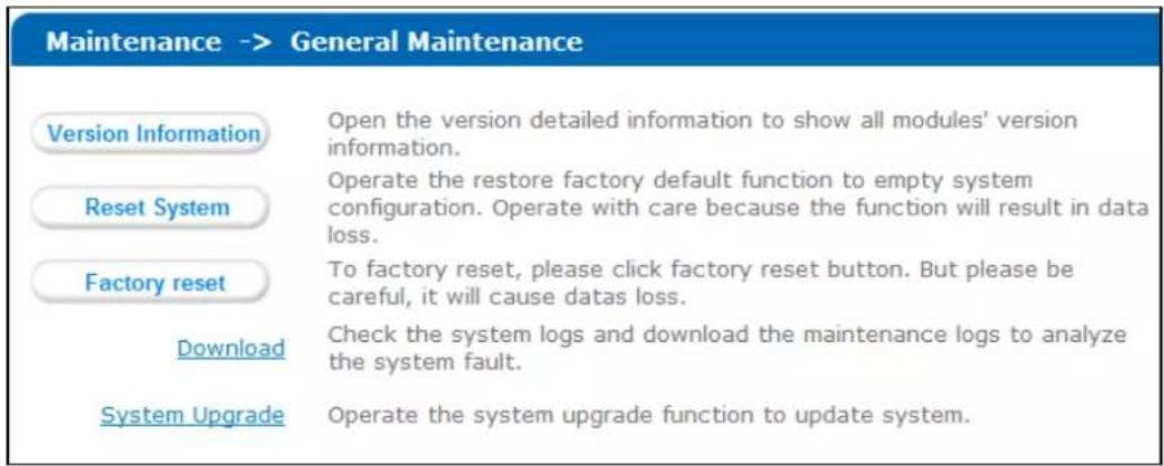
Figure 3.6 General
3.3.1 Viewing Version Information
Purpose:
Version information interface lists information including SMI, HYBRID SAN, Support, and so on.
Steps:
-
Click Versioninformation to pop up version information window.
-
Click Cancelto close the window.
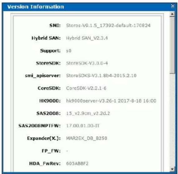
Figure 3.7 Version Information
3.3.2 Default Settings
Purpose:
You can reset system to factory defaults when system is abnormal. You are recommended to reset system under the direction of professional technical support.

Resetting operation won't restore administrator user name and password, RAID configuration, hot spot configuration, and network parameters.
Steps:
- Click Resetsystemto pop up reset system dialog.
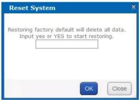
Figure 3.8 Reset System
- Enter yes or YESintext field and click OK to reset.
3.3.3 Managing Maintenance Log
Purpose:
When system is abnormal, you can download the maintenance log to analyze problems.
Steps:
For details, refer to 9.1 OperationLog.
3.3.4 Modifying Password
Purpose:
You can modify password for basic management system and HYBRID SAN sub-system user.
Steps:
- Click Modify password.And modify password window appears.
- Select UserName as web_admin or nvr_admin.
web_admin: Basic management system user name.
nvr_admin:HYBRID SAN sub-system user name.
- Enter Old Management Password and the same password in New Management Password and Confirm Management Password.

● The security level of modified password should not be lower than low security.
- Password can only contain numbers, lowercase, uppercase, and underline for your password.
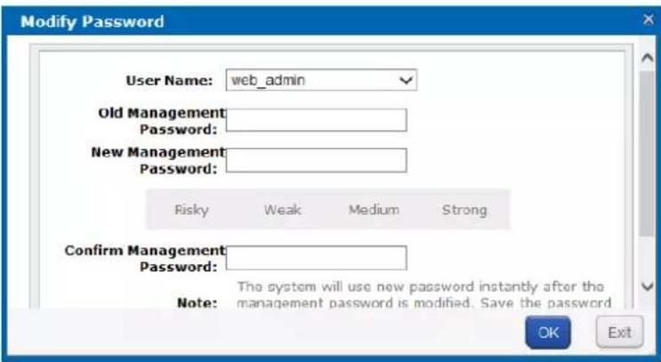
Figure 3.9 Modify Password
- Click OK and click OK in popup message dialog to save the new password.

• Once password is modified, it jumps to login interface. You need to enter the new password to log in.
• Another controller password changes with the current controller password.
3.3.5 SNMPConfiguration
Purpose:
By configuring SNMP parameters, you can log in PRTG Traffic Grapher tool to monitor the system status, including exception information, CPU usage, and so forth.
Steps:
- Click SNMPConfiguration button.
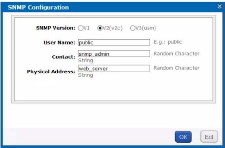
Figure 3. 10 SNMP Configuration
- SNMPVersionis V2(v2c) by default and is not editable.
- Enter UserName, Contact, and Physical address.
- Click OK to save the settings. Then you can view system status by logging in PRTG Traffic Grapher Tool.
3.3.6 Modifying Host Name
Steps:
-
Click Modify and text field appears.
-
Enter host name in the text field.
- Click Modify to activate the new host name.

Figure 3.11 Modify Host Name

Only letters (a to z and A to Z), numbers (0 to 9), and underline (_) can be input.
3.3.7 Viewing ServiceStatus
Purpose:
Whether the services are running or not. You can enable, disable, or restart the services.
Steps:
- Click Enableto start the service that is not running.
- Click Disableto shut down the running service.
- Click Restart to restart services.
| Enabling and Disabling of Services (Total: 2) | ||
| Service Name | Current Status | Service Operation (Enable/Disable/Restart) |
| SNMP | Running | Enable Disable Restart |
| iSCSI | Running | Enable Disable Restart |
Figure 3. 12 Service Status
3.3.8 SystemUpgrade
Purpose:
You are recommended to upgrade system under the help of professional support.
Steps:
- Click Systemupgrade in Common menu to enter Application Service interface.

Figure 3. 13 Application Service
- Click Browser and choose the upgrade package.
- Click Uploadto upgrade. After upgrade succeeded, reboot the storage system to activate the new version.
- Optionally, you can click Restore to restore to previous version.

You can only restore to the last upgraded version.
3.4 Graphical Display
Purpose:
The storage system provides a graph to show the front view status and a pie chart to show the storage information.
Step:
Click Maintenance in navigation bar and choose GraphicalDisplayto enter Graphical Display interface.
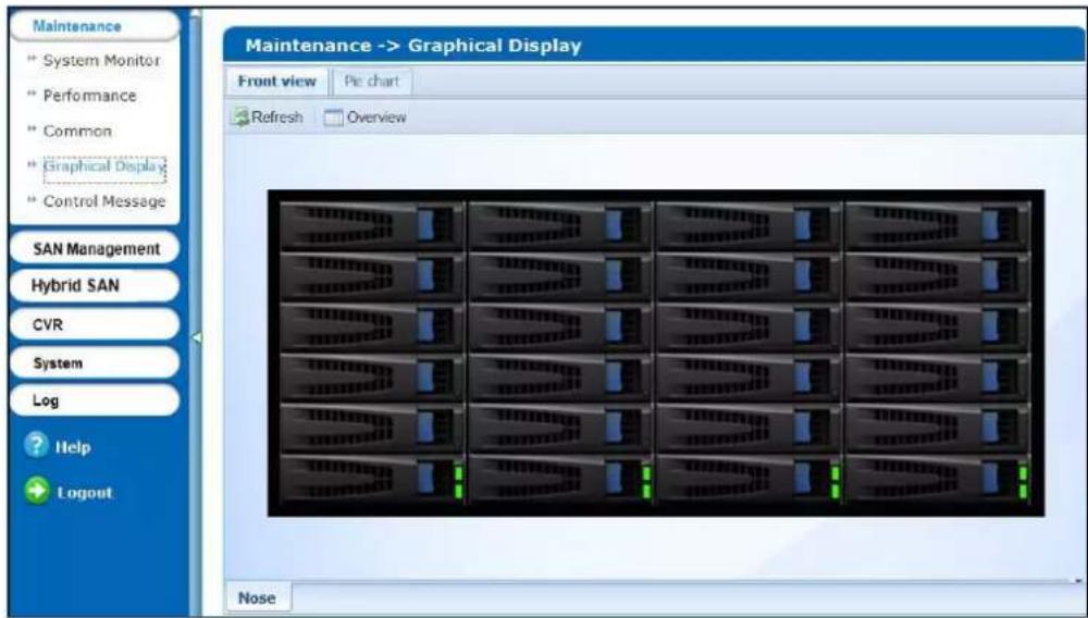
Figure 3. 14 Graphical Display
3.4.1 Front View
Purpose:
Front view can show you the HDD status.
Steps:
- Click Front View in Graphical Display menu to show front view.
Table 3.2 Indicator Status Description
| Indicator Color Description | ||
| Top indicator | Unlit | HDD doesn’t exist. |
| Green | HDD is connected and recognized. | |
| Bottom indicator | Green | HDD is normal. |
| Blue | Reading and writing normally. | |
| Red HDD is rebuilding. | ||
- Positioning the pointer in a green indicator slot. Then the message dialog appears.
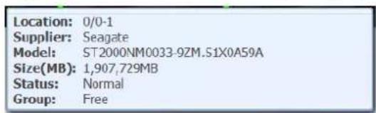
Figure 3. 15 HDD Information
- Click Overview to view information of all HDD.
| Position | Supplier | Model | Capacity (MB) | Status | Group |
| 0/0-1 | Seagate | ST2000NM0001.Z1P105J3 | 1,907,729 | Normal | Array |
| 0/0-3 | Seagate | ST2000NM0001.Z1P10PRH | 1,907,729 | Normal | Array |
| 0/0-4 | Seagate | ST8000NM0075 ZA103VH6000J607VTV9 | 7,630.885 | Normal | Array |
| 0/0-5 | Seagate | ST2000NM0001.Z1P10KV9 | 1,907,729 | Normal | Array |
| 0/0-6 | Seagate | ST8000NM0075 ZA102T5FC000J607TUCD | 7,630.885 | Normal | Array |
Figure 3. 16 HDD Overview
- Optionally, click Refreshin top-right corner to update the front view.
3.4.2 Pie Chart
Purpose:
Pie chart shows the free size of all storage modules, including system, LUN, snapshot, HYBRID SAN, iSCSI, and FC. Steps:
- Click Pie Chart in Graphical Display to enter Pie Chart interface.
- Positioning the pointer in the part you want to view. Freesize and free size Percentage appear in a dialog.
- Optionally, click Refreshin top-right corner to update the information.
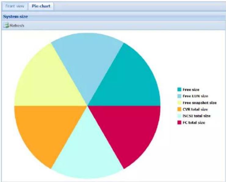
pie
| Category | Value | | ------------------ | ----- | | Free size | 25% | | Free LUN size | 20% | | Free snapshot size | 30% | | CVR total size | 25% | | ISCSI total size | 25% | | FC total size | 25% |Figure 3.17 Pie Chart
3.5 Environmental
Purpose:
Environmental shows the fan information, module temperature, fan control panel version, and chassis power.
Steps:
- Click Maintenance in navigation bar and choose Control Message to enter Control Message interface. Fan RPM (Revolutions per Minute), temperature, and other information are shown.

You can install or uninstall fans. Up to 6 fans' formation can be connected.
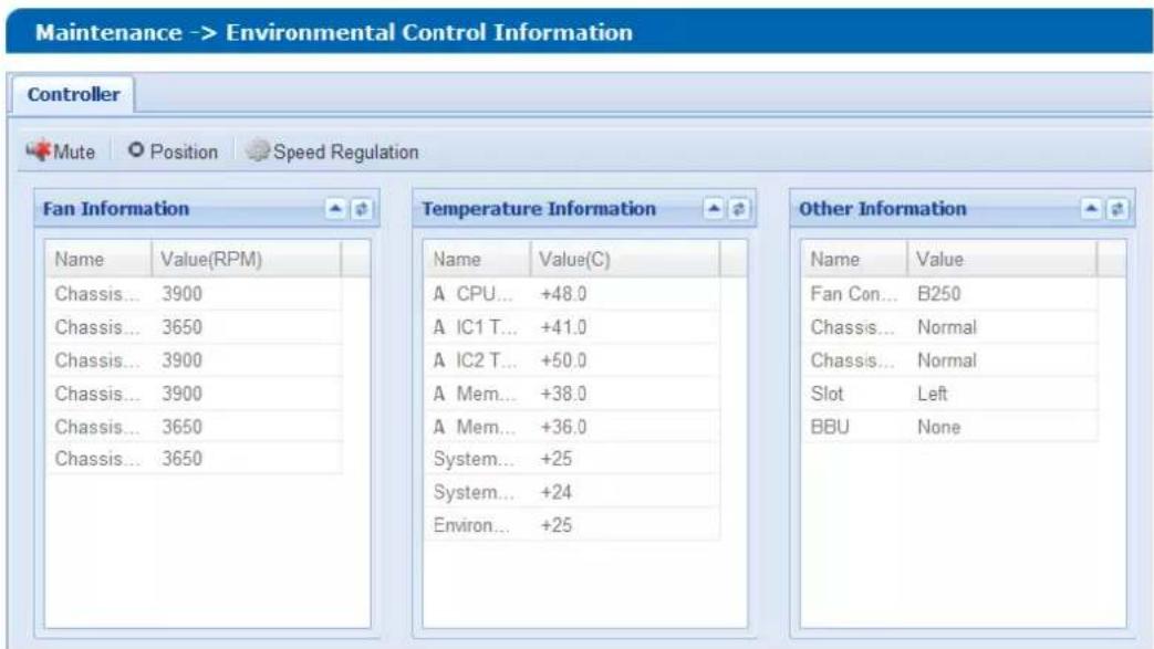
Figure 3.18 Host
-
Click Mute in top-right corner to turn off system audible warning.
-
To find out which controller is working, click Positionin top-right corner and click OKin popup dialog. The FN indicator of working controller would light up and flash for 10 minutes.
-
Set fan speed.
1) Click SpeedRegulation in top-right corner to pop up dialog box.
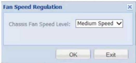
Figure 3.19 Fan Speed
2) Choose speed as Low speed, Medium speed, or High speed in dropdown list.
3) Click OK to save the settings.
Chapter 4 Storage Management
Purpose:
Storage management provides configuration including HDD management, array, storage pool, LUN (logical Volume), and storage settings.
Table 4.1 Module Description
| Module Description | |
| HDD Management | You can:View HDD information and status.Rescan, positioning, initialize, and detect HDDs. |
| Array | You can:Create arrays.Add hot spare.View array and hot spare information.Delete array and hot spare. |
| Storage pool | You can:Add, delete, and positioning storage pools.Remove and positioning HDDs.View system total and free capacity. |
| LUN (Logical volume) | You canAdd and delete LUNs.Rename, expand, clone, and snapshot LUNs. |
| Configurations | You can:Set array synchronization speed.Set array synchronization type.Set flicking frequency for HDD positioning indicator. |
Keywords:
HDD Management, Array, Storage Pool, LUN (Logical Volume), Configuration
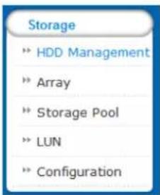
Figure 4.2 Storage
4.1 Managing Local HDD
Purpose:
You can view the HDD information here, including HDD location, supplier, model, size, status, and belonging group.
Step:
Click Storagein navigation bar and choose HDDManagement.

Figure 4.3 HDD Management
4.1.1 Viewing HDDStatus
Purpose:
You can view status of one HDD or all HDDs.
4.1.1.1 One HDD
Steps:
- In the HDD information list, Click Details of an HDD. HDD state dialog appears.
- Click SMARTtoview the HDD SMART detection information.
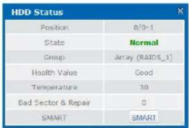
Figure 4.4 HDD Status
4.1.1.2 All HDDs
Steps:
- Click HDDStatusin the upper left corner.
- Click SMARTofan HDD to view its SMART detection information.
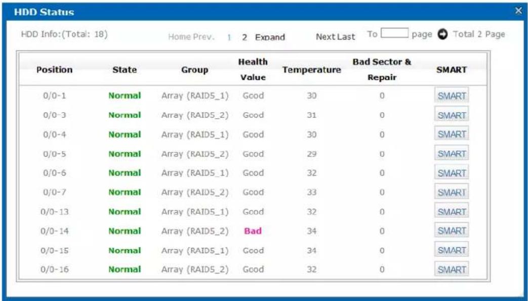
Figure 4.5 HDD Status

There are totally 6 kinds of status for an HDD.
Table 4.2 HDD Status Description
| Status Description | |
| Normal HDD | works normally. |
| Undetected HDD | failed the HDD detection. |
| Lost HDD is unrecognized. | |
| Risky | Exception occurs during HDD detection. But it can still work. |
| Bad | HDD is kicked out by an array. |
| Warning | HDD read and writing speed is higher than 10 MB/S during pressure test. |
4.1.2 Rescanning HDD
Step:
- If detecting a newly installed HDD failed, click Rescantofind the HDD.
- If an HDD is uninstalled from the storage system, click Rescantoremove it from the HDD interface.

Rescanning HDDs may result in HDD status appearing as Unknown. Fresh the interface or click Rescanagain to solve the problem.
4.1.3 Positioning HDD
Purpose:
HDD bottom indicator flickers after enabling the function. It enables you to find a certain HDD more easily. Before you start:
Set the flickering time first. For details, refer to 4.5.2 FlickeringTime.
Steps:
-
Check the checkbox of HDD you want to find.
-
Click Position and click OK in popup dialog box. Then HDD indicator keeps flickering in red for the set flickering time.
4.1.4 HDDInitialization
Purpose:
To recover an HDD when its status is uninitialized or when it is kicked out by an array, you can initialize it.
Steps:
-
Check the checkbox of HDD you want to initialize.
-
Click Initialize and click OKin popup dialog box to start initializing.
4.1.5 HDDDetection
Purpose:
To recognize an HDD which is added to a storage system for the first time, detect it.
Steps:
-
Check the checkboxes of HDDs to detect.
-
Click Detect.
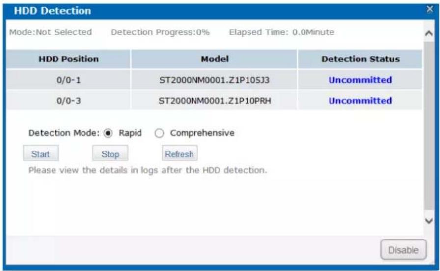
Figure 4.6 HDD Detection
- Select the Detection Mode as Rapid or Comprehensive.
Rapid: Detect parts of all HDD blocks. It takes shorter time than Comprehensive.
Comprehensive: Detect all HDD blocks. It takes longer time than Rapid.

It is recommended to operate rapid detection when system is under low pressure.
● You are recommended to operate comprehensive detection for the first use HDD.
● To keep data safe, detect an HDD every 3 months.
-
Click Start to start detecting. The selected detection mode, detection progress, and detection time are listed in the top part of the interface.
-
Optionally, click Refreshto update the detection status, detection process and detection time.
Or you can click Stop to end all detections.

There are 3 kinds of detection status: Unsubmitted, Detecting, and Completed.
Table 4. 3 Detection Status Description
| CheckStatus Description | |
| Uncommitted | HDD detection has not been committed. |
| Detecting HDD is being detected. | |
| Waiting | Another HDD is being detected. You need to wait till the detection is finished. |
4.2 Array
Purpose:
You can create and manage array.
Step:
Click Storage in navigation bar and choose Array.
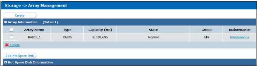
Figure 4.7 Array
4.2.1 Creating Array
Purpose:
You can use available HDDs to create array.
Steps:
- Click CreateArray.
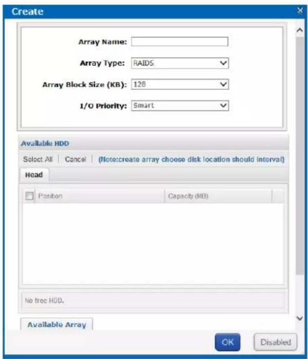
Figure 4.8 Create Array
-
Input Array Namein text field.
-
Select Array Type in drop-down list. RAID 0, RAID 1, RAID 3, RAID 5, RAID 6, RAID 10, and RAID 50 are selectable.
Figure 4.9 Required HDD Quantity
| Array Type | Required HDDQuantity |
| RAID 0 | At least 2 HDDs. |
| RAID 1 | At least 2 HDDs. |
| RAID 3 | At least 3 HDDs. |
| RAID 5 | Valid range: [3, 12]. |
| RAID 6 | At least 4 HDDs. |
| RAID 10 | RAID is made of RAID 0 and RAID 1 which requires at least 4 even HDDs. |
| RAID 50 | RAID is made of RAID 0 and RAID 5 which requires at least 6 even HDDs. |
-
Select Array BlockSize(KB)indrop-down list.
-
Select I/O Priority as Performance Priority, Protection Priority, Balanced, or Smart.
➢ PerformancePriority: To guarantee external IO task performance, internal IO task is totally stopped.
➢ Protection Priority: To guarantee internal IO task performance, external IO task would only take the rest channel.
Balanced: When both internal and external IO task exist, Balance ensures internal IO task occupy certain channel without influencing external IO task.
Smart: Without external IO task, array is initialized in the highest speed. Or array is initialized in the lowest speed.

If RAID level is RAID 0, I/O priority is unavailable.
6. Select the Available HDDsto create RAID.
Or select Availablearraysto create RAID.
Or select the combination of Available HDDsand Available arrays.

● Only enterprised HDDs are listed in Available HDDs list.
- In order to increase the performance of created RAID, it is recommended to use HDDs of the same model and capacity when creating a RAID.
7. Click OK to create array. The successfully created array lists in Array information list. Once created, the array starts initializing.
4.2.2 Array Exception
Purpose:
If HDD failure occurs, array degrades. When more HDDs fail, array fails. Degraded array can keep working. However, failed array cannot work. Notification area will notify you once array degraded or failed. Refer to following table for array degraded and failed condition.
Table 4. 4 Array Degraded Condition
| RAID Level | DegradedCondition | Failed Condition |
| RAID 0 | RAID 0 will not degrade. | One HDD fails. |
| RAID 1 | N-1 HDDs fail. | All HDDs fail. |
| RAID 3 | One HDD fails. | Two HDDs fail. |
| RAID 5 | ||
| RAID 6 | N-1 HDDs fail. | More than three HDDs fail. |
| RAID 10 | One HDD fails. | Two HDDs fail in either contained RAID. |
| RAID 50 |

- If array in storage pool degrades, physical volume degrades.
- If array in storage pool fails, physical volume fails.
4.2.3 Rebuilding Array
Purpose:
Rebuilding refers to the process of using a normal HDD or array to virtually replace a failed HDD in a degraded array. The normal HDD can be hot spare HDD, newly inserted HDD, and so forth.

● During rebuilding process, if the rebuilding HDD fails, the array stays degraded.
● During rebuilding process, if a normal HDD in array fails, the array becomes failed.
● During rebuilding process, if I/O error occurs to the rebuilding HDD, you need to change rebuilding HDD.
4.2.3.1 Rebuilding with Hot Spare
Beforeyou start:
Add global, area, or local hot spare HDD or array for array.
Step:
Once the array degraded, hot spare HDD or hot spare array automatically rebuilds the array.

When the degraded array possesses both global and local hot spare, it rebuilds with local hot spare preferentially.
4.2.3.2 Rebuilding with Available HDD
Beforeyou start:
Ensure there is at least one available HDD which isn't included in any array or storage pool.
Steps:
- Click Maintenance of a degraded array in Array information list.
- Click Rebuild to pop up Array rebuild interface.
- Select an Available HDDor Available Array.
- Click OK to start rebuilding.
4.2.4 Detecting Array
Purpose:
You can detect whether the data bit and parity data in an array match or not.

If array in storage pool starts detecting, the physical volume status is detecting.
Steps:
- Click Maintenance of a degraded array in Array information list.
- Click Detect to start detecting.
4.2.5 Repairing Array
Purpose:
You can repair the data bit and parity data mismatch issue.

If array in storage pool starts repairing, physical volume status is repairing.
Steps:
- Click Maintenance of a degraded array in Array information list.
- Click Repair to start repairing.
4.2.6 Renaming Array
Steps:
- Click Maintenance of an array in Array information list.
- Click Rename.
-
Enter a new name.
-
Click OK to save the new name.
4.2.6.1 Modify I/O Priority
Steps:
- Click Maintenance of an array in Array information list.
- Click Modify.
- Select I/O Priority in dropdown list.
- Click OK.
4.2.6.2 Pause Initialization/Rebuilding/Detection/Repair
Purpose:
When the array is initializing, rebuilding, detecting, or repairing, you can pause.
Steps:
- Click Maintenance of an array in Array information list.
- Click Pauseto pause current process.
- You can click Keep to resume.
4.2.7 Deleting Array
Steps:
- Check the checkbox of array you want to delete.
- Click button to delete.

If the array has been added to a storage pool, you need to remove it from storage pool first, or it can't be deleted.
4.2.8 Adding Hot Spare
Purpose:
The hot spare HDD can replace failed HDD in the degraded array. In order to protect data from damage in case of HDDs in array fail, it is recommended to add hot spare HDDs for a created array.

RAID 0 will not degrade. So you need not add local hot spare HDD for it.
Steps:
- Click Add Hot SpareDiskto enter Add hot spare interface.
- Select Group as Global, Area, or Local.
Global: Global hot spare HDDs can replace failed HDDs in any degraded arrays of storage devices in the same system.
Area: Area hot spare HDDs replace failed HDDs in any degraded arrays of one storage system.
Local: Local hot spare HDDs replace failed HDDs in designated array.

Priority of hot spare: Local hot spare > area hot spare > global hot spare
- If Group is Area, select available array in Area dropdown list.
If Group is Local, select array in Array dropdown list.
- Select at least one Available HDD.
Or select at least one Available array.
Or select the combination of Available HDD or Available array.
- Click OK to create hot spare.
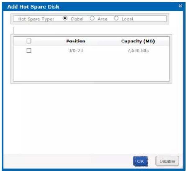
Figure 4. 10 Add Hot Spare
4.2.9 Deleting Hot Spare
Steps:
-
Select arrays you want to delete.
-
Click button to delete.
4.3 Storage Pool
Purpose:
Storage pool, which is made of physical volumes and contains arrays and HDDs, is designed for central management of storage capacity.
Step:
Click Storagein navigation bar and choose StoragePool.
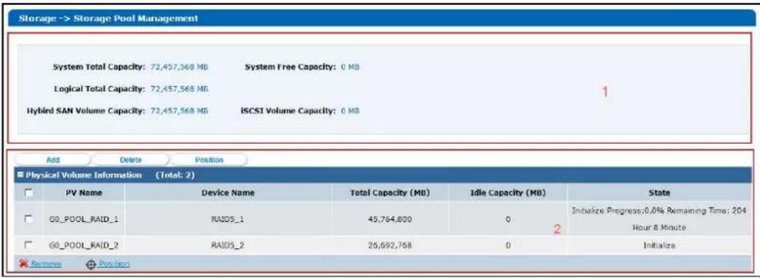
Figure 4. 11 Storage Pool
Table 4.5 Interface Description
| Area | Name Description | |
| 1 | Information Area | Lists the storage pool total size, free size, LUN size, snapshot size, HYBRID SAN size, iSCSI size, and FC size. |
| 2 | Configuration Area | You can add, delete, and positioning created physical volume here. |
4.3.1 Adding Storage Pool
Purpose:
You need to create physical volumes to build storage pool.
Before you start:
Ensure available array or HDD exists in the storage system.
Steps:
- Click Add.
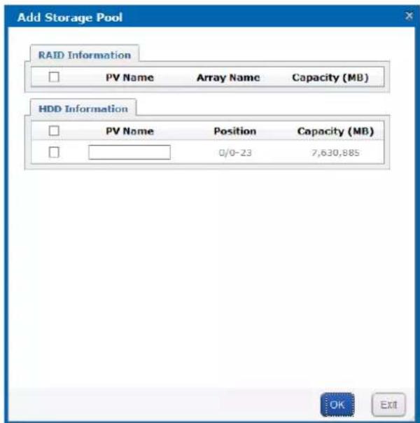
Figure 4. 12 Add Storage Pool
- Select at least one array or HDD as storage pool.
Or select the combination of array or HDD.
-
Input PVNamein text field.
-
Click OK to add the storage pool.
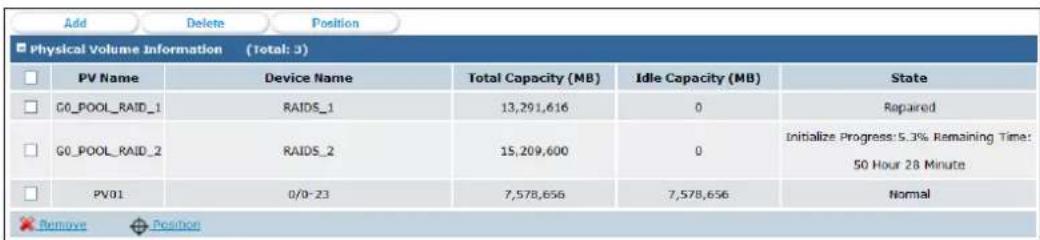
Figure 4. 13 Storage Pool
4.3.2 Deleting StoragePool
Purpose:
You can delete storage pool by deleting the added physical volumes.
Steps:
-
Check the checkboxes of physical volumes you want to delete.
-
Click or button to delete them.


Idle physical volumes can be deleted except the first created physical volume.
4.3.3 Positioning StoragePool
Beforeyou start:
Set the flickering time first. For details, refer to 4.5.2 FlickeringTime.
Steps:
-
Check the checkbox of physical volume you want to positioning.
-
Click Position button. Then the HDD bottom indicator keeps flickering in green for the set flickering time.
4.4 LogicalVolume
Purpose:
Logical volume is the virtual HDD which is made of physical HDD.
Step:
Click Storagein navigation bar and choose LUN.
| Storage -> Logical Volume Management | ||||||||||
| Create | ||||||||||
| LUN Information (Total: 8) | ||||||||||
| ID | Name | Block Size (Byte) | Capacity (MB) | Physical Volume | Usage | Snapshot Number | Clone | Extend | Rename | |
| 0 | LUN_BACK1 | 512 | 51,200 | G0_POOL_RAID_1 | CVR Reserved Volume | 0 | ||||
| 1 | LUN_BACK2 | 512 | 51,200 | G0_POOL_RAID_1 | CVR Reserved Volume | 0 | ||||
Figure 4. 14 Logical Volume
4.4.1 Creating LogicalVolume
Purpose:
You can create logical volumes by using available physical volumes.
Steps:
- Click Create.
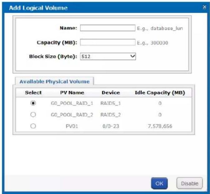
Figure 4. 15 Create Logical Volume
- Enter Name.
- Enter Capacity(MB).
- Select BlockSize(Byte) from dropdown list.
- Choose Available PhysicalVolume.
- Click OK to create logical volume. Created logical volume is listed in logical volume information list.
4.4.2 Deleting LogicalVolume
Steps:
- Select the logical volume you want to delete.
- Click button to delete them.

The working logical volume can be deleted. Only free logical volume can be deleted.
4.4.3 Renaming Logical Volume

You can only rename the free logical volumes.
Steps:
- Click button of the logical volume you want to rename.
- Enter a new name.
- Click OK to save the new name.
4.4.4 Enlarging Logical Volume
Purpose:
You can enlarge the size of created logical volume.

You can only enlarge the idle logical volumes.
Steps:
- Click button of the logical volume you want to extend.
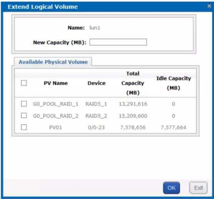
Figure 4. 16 Extend LUN
- Enter New Capacity(MB).
- Select Available PhysicalVolume used to extend.
- Click OK to extend.
4.5 Configuration
Purpose:
You can set the array synchronization speed type and flickering time of positioning indicator.
Step:
Click Storagein navigation bar and choose Configuration.
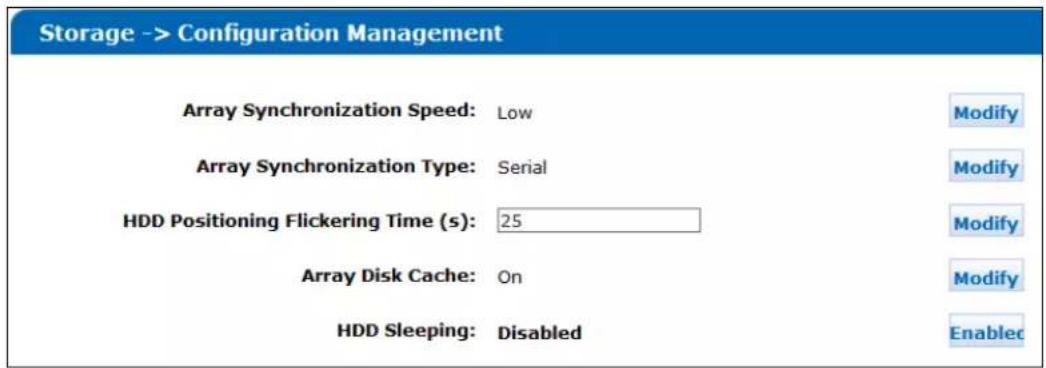
Figure 4. 17 Configurations
4.5.1 Synchronization Speed and Type
Purpose:
Array synchronization speed and synchronization type is editable.
Steps:
- Click Modify of Array SynchronizationSpeed.
- Select Array Synchronization Speed as High, Medium, Low, or None.

The faster the speed is, the highest the internet IO percentage is.
- Click OK.
- Click Modify of Array SynchronizationType.
- Select Array Synchronization Type as Serial or Parallel.
- Click OK.

Figure 4. 18 Synchronization Speed and Type
4.5.2 Flickering Time
Purpose:
When positioning an HDD, the HDD bottom indicator keeps flickering for the set time.
Steps:
- Enter a number as flickering time in HDDPositioning Flickering Time (s).

Valid flickering time ranges from 5 to 300 and the unit is second.
- Click Modify.
Chapter 5 SAN
Purpose:
You can add iSCSI disks and FC (Fiber Channel) disks in your computer.
Table 5.1 Module Description
| Module Description | |
| iSCSI | You can add iSCSI disks in your computer. |
| FC | You can add FC disks in your computer. |
Keywords:
iSCSI, FC
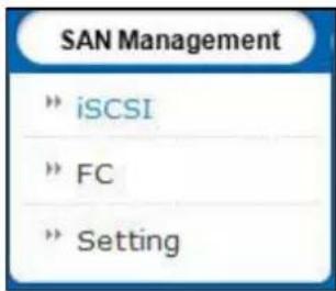
Figure 5.2 SAN
5.1 iSCSI
Purpose:
You can add iSCSI HDDs in your computer.
Step:
Click SANin navigation bar and choose iSCSItoenter iSCSI interface.
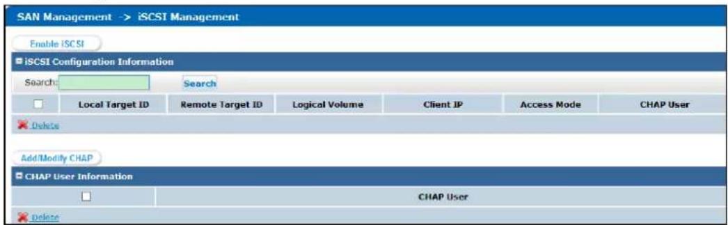
Figure 5.3 iSCSI
5.1.1 Adding CHAPUser
Purpose:
When enabling iSCSI, you can select an added CHAP user as a way to verify your computer permission.
Steps:
- Click Add/Modify CHAP button to enter Add CHAP User interface.
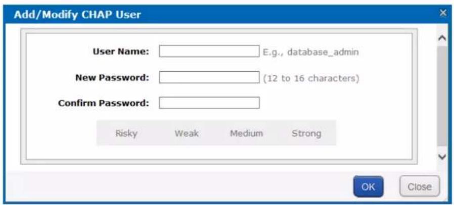
Figure 5.4 Add CHAP User
- Enter CHAP UserName, New Password, and Confirm password.
Username: Only letters, numbers, and underline are allowed.
New Password: Only 12 to 16 characters, including letters, numbers, and underline, are allowed.
Confirm Password: It must be the same as New Password.
- Click OK and click OK in confirmation dialog box to add the CHAP user.
5.1.2 Modifying CHAPUser
Purpose:
You can modify the password of added users.
Before you start:
If the CHAP going to be modified is linked to one or more iSCSIs and these iSCSIs are connecting with computers, you need to disconnect them from computer first.
Steps:
- Click Add/Modify CHAP button to enter Modify CHAP User Interface.
- Enter the CHAP username you want to modify in the text field.
- Enter a new Password and Confirm password.
- Click OK and click OK in confirmation dialog box to modify the CHAP user.
5.1.3 Enabling iSCSI
Purpose:
Enabling iSCSI in the storage system makes it possible for you to add iSCSI HDDs in computer.
Steps:
- Click Enable iSCSI button to pop up Enable iSCSI interface.
![Enable iSCSI Service Client IP: E.g., 192.168.40.60 Local Target ID: E.g., 100 (Range [1,1024]) Remote Target ID: E.g., 200 (Range [1,1024]) CHAP User: Disable Access Mode: Read/Write Logical Volume Select Name Block Size(B) Capacity (MB) Physical Volume Status OK Close](/content/2026/05/972766/images/fb5cfedd1a83ddf5b4e0e889751bbf8020fbb9ae691f50d8f8a42ac2d9c1d868.jpg)
Figure 5.5 Enable iSCSI
- Enter Client IP and iSCSIID.
ClientIP: To turn on iSCSI for a specified client (computer), enter the client IP address. To turn on iSCSI for multiple clients, enter 0.0.0.0 in the text field.
- Select the identity authentication method in the dropdown list of CHAPUser.
➢ Disable: There is no limit for client access.
Other CHAP user: Correct CHAP user name and password are needed for client to get access to LUN.
- Select the logical volume AccessMode as Read/Write, Write-Through, ReadOnly, or Intelligent Read-Only.
Read/Write: Read and writing permission.
Intelligent Read-Only: Event though writing operation succeeded, data wouldn't be written into LUN. It is mainly used to test the storage system performance.
Write-Through: It writes the data into HDDs directly without writing into HDD buffer. A low writing speed makes the data complete.
- Choose an available LogicalVolume.
- Click OK to enable the iSCSI.

When multiple iSCSIs share the same LUN, only one iSCSI server access mode can be R/W and other servers should be RO or IRO, or file system may be damaged or data may lose.
5.1.4 Disabling iSCSI
Purpose:
For the unnecessary iSCSIs, you can disable them, thus to keep the storage system safe and stable.
Beforeyou start:
Disconnect the storage system from the clients for which you want to disable iSCSI.
Steps:
- Check the checkbox of iSCSI you want to disable.
- Click and click OKin confirmation dialog box.
5.1.5 Modifying iSCSIPort
Purpose:
iSCSI port is needed when accessing via computer. It can be edited.
Beforeyou start:
Disconnect all iSCSIs first, or iSCSI enabled under pervious iSCSI port couldn't be deleted.
Steps:
- Click SANin navigation bar and choose Setting to enter Setting interface.
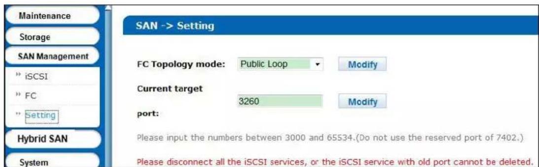
Figure 5.6 Setting
- Enter a number between 3000 and 65534 except 7402 in Currenttarget port text field.
- Click Modify, click OKin confirmation dialog box, and click OKin second popup dialog box.
5.2 FC(Optional)
Purpose:
You can add FC HDDs in your computer.
Beforeyou start:
- Install fiber Ethernet adapter and fiber Ethernet adapter drive in both the storage system and the client server.
- Connect the storage system and client server to fiber channel switch with fiber.
Step:
Click SANin navigation bar and choose FCto enter FC interface.

Figure 5.7 iSCSI
5.2.1 Enabling FC
Purpose:
Enabling FC in the storage system makes it possible for you to add FC HDDs in computer. To visit FC HDD via computer, the storage system and the computer should locate in an optical fiber network. You can enable FC service for:
A specified fiber channel.
All available fiber channels.
A specified FC port.
All available FC ports.
Before you start:
• Install optical fiber card first.
● Create at least one LUN first. For detailed steps, refer to 4.4 Logical Volume.
Steps:
- Click EnableFCto enter Enable FC interface.
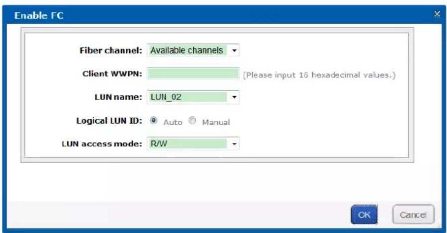
Figure 5.8 Enable FC
- According to actual connection, select Fiber Channelsas Fiber Channel0, Fiber Channel1, Fiber Channel2, or Fiber Channel3. If you are not sure about selecting which one, select Available channels. The storage system can automatically connect the client with an available channel.

Fiber Channel 0 refers to fiber port 1 in real panel. Fiber Channel 1 refers to fiber port 2 in rear panel. And so on.
- To specify a client, enter Client WWPN of 16 numbers.
ClientWWPN:The client fiber Ethernet adapter WWPN. You can use a fiber client to obtain WWPN. If no client is available, enter 000000000000000. The storage system connects all available clients WWPN and share FC with all connected clients.
-
Select available LUN in the dropdown list of LUNname.
-
Choose LogicalLUNID as Auto or Manual.
Auto: The storage system automatically specifies a free LUN ID.
➢ Manual: It is recommended to choose Manual. The logical LUN ID which is the first manual one must be 0.
- Select LUN access mode as R/W, SR/W, RO, or IRO.
R/W: Read and writing permission.
IRO(Intelligent Read Only): Even though writing operation succeeded, data wouldn't be written into LUN. It is mainly used to test the storage system performance.
RO:Read only
SR/W(Synchronous Read/Write): It writes the data into HDDs directly without writing into HDD buffer. A low writing speed makes the data complete.
- Click OK and click OK in confirmation dialog box to enable FC.
5.2.2 Disabling FC
Purpose:
You can disable FC service for:
A specified fiber channel.
All available fiber channels.
A specified FC port
All available FC ports.
Steps:
-
Check the checkbox of FC you want to disable.
-
Click and click OKin confirmation dialog box.
Chapter 6 HYBRIDSAN
Purpose:
You can configure HYBRID SAN and N+1 parameters.
Table 6.1 Module Description
| Module Description | |
| HYBRID SAN | You can:Configure private volume, HYBRID SAN configuration, create record volume, and extend record volume.HYBRID SAN one-key configuration.Manage N+1.Log in HYBRID SAN sub-system to add encoders, add strategy, search video, and so forth. |
| N+1 | A storage system whose HYBRID SAN service has started can serve as a backup HYBRID SAN for other HYBRID SAN s. |
Keywords:
HYBRID SAN, N+1
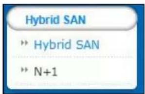
Figure 6.2 HYBRID SAN
6.1 One-KeyConfiguration
Purpose:
Quick-setting creating helps you to create HYBRID SAN quickly.
Beforeyou start:
Ensure there is neither storage pool nor array in the storage system.
Steps:
- Click the One-KeyConfigurationbutton in upper right corner to start quick settings.
- Click OK to confirm. Quick-setting takes 3 to 15 minutes. During the quick-settings, following operations are performed automatically.
1) Add HDDs to storage pool. Or create RAIDs and add them to storage pool.

The whole HDDs are added to storage pool with no more free capacity. You can view the storage pool usage in Storage > Storage Pool.
2) Create private volume, reserved volume, and record volume. If more than 3 LUNs are created, one archive volume is created.
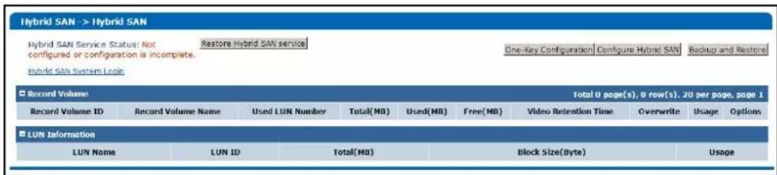
Figure 6.3 HYBRID SAN Settings Interface

Bad HDD, risky HDD, and warning HDD would not be added to storage pool.
Non-enterprise HDD is added to storage pool by single-HDD mode.
Quick-setting takes longer if any undetected HDD exists.
If HDDs in the storage system are less than 6, they are added to storage pool by single-HDD mode.
If HDDs in the storage system are not less than 6 and HDDs in storage enclosure is less than 6, the storage system HDDs are added by array mode and the storage enclosure HDDs won't be added.
If HDDs in the storage system and HDDs in storage enclosure are both not less than 6, they are both added to storage pool by array mode.
If only one HDD exists, no reserved volume is created. In single-HDD mode, no reserved volume is created in the last HDD of the storage system. In array mode, two reserved volumes are created in each RAID.
By default, a 50 GB size private volume and a 50 GB size reserved volume should be created.
6.2 HYBRIDSAN Configuration
Purpose:
You can start and reset HYBRID SAN and create record volume.
Step:
Click the Configure HYBRIDSAN button in upper right corner.
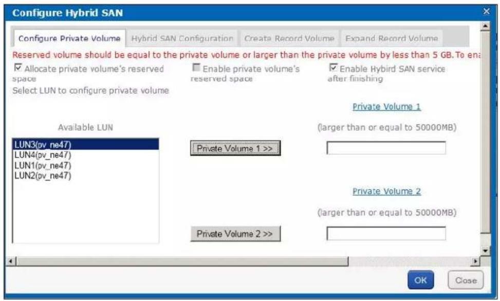
Figure 6.4 HYBRID SAN
6.2.1 Starting HYBRIDSAN
Purpose:
You can start HYBRID SAN after private volumes are created.
Before you start:
- To create storage pool, do one of the following:
● Single-HDD mode: Add HDDs to storage pool.
- Array mode: Create arrays and add them to storage pool.
- Create at least 5 LUNs. Ensure at least 4 of them are larger than 20 GB. The four LUNs are used to create private volume, reserved volume. Other LUNs are used to create record volume.

If record volume size is fewer than 120T, then private volume 1 and private volume 2 size should both larger 50G.
If record volume size ranges from 120T to 180T, then private volume 1 and private volume 2 size should both larger 60G.
If record volume enlarges by 60T, record volume 1 and record volume 2 should both enlarge by 10G.
Steps:
- Click the Configure Private Volume tab.
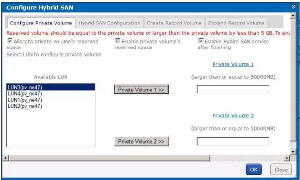
Figure 6.5 HYBRID SAN Configuration
- Check the checkbox of EnableHYBRIDSAN after finishing.
- Optionally, check the checkbox of Allocate private volume's reserved space and Enable private volume's reserved space.
Enable private volume's reserved space: Create a spare volume for private volume. The spare volume works as a backup volume. When error occurs to the two private volumes, the two spare LUNs would replace them.

It is not recommended to use a spare volume in the same physical volume with the private volume.
- To add private volume 1, choose a FreeLUNand click Private volume 1 >> button.
- To add private volume 2, choose a FreeLUNand click Private volume 2 >> button.

HYBRID SAN configuration information is saved in private volume 1 and private volume 2.
It is not recommended to use the LUN created by the HDD first added to storage pool to create private volume 1.
The chosen LUNs' capacity should meet the demand shown in red frames in Figure 6.5 HYBRIDSAN Configuration.
If Allocate private volume's reserved space and Enableprivate volume's reserved space are selected, the storage system automatically select two free LUN as the spare volumes.
- Click OK to start creating the two private volumes. After private volumes are created, HYBRID SAN starts running.
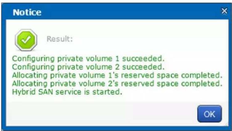
Figure 6.6 Created Private Volume
Table 6.2 HYBRID SAN Status Description
| Status Description | |
| Not configured or incomplete | HYBRID SAN is not configured. |
| Running HYBRID SAN is correct | y started. |
| Stopped | Click Stop HYBRIDSAN to stop HYBRID SAN service. Once HYBRID SAN is stopped, you are not able to view encoder information and videos. You can click Start HYBRIDSAN to recover to Running status. |
| Running and Recovering | Indicators HYBRID SAN is working normally and in automatic recovery process. |
| Stopped and Recovering | Indicators HYBRID SAN is stopped and in automatic recovery process. |
6.2.2 Resetting HYBRIDSAN
Purpose:
You can delete HYBRID SAN videos, encoders, and other configurations by resetting HYBRID SAN. After reset, HYBRID SAN status restores to not configured or incomplete.
Steps:
- Enter HYBRID SAN configuration menu.
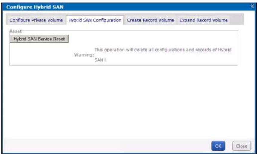
Figure 6.7 Reset HYBRID SAN
- Click HYBRIDSAN Service Reset.
- Enter yes or YESintext field to start reset.
6.2.3 RecordVolume
Purpose:
Record volume is the logical volume stores videos.
6.2.3.1 Creating RecordVolume
Steps:
- Click CreateRecordVolume menu.
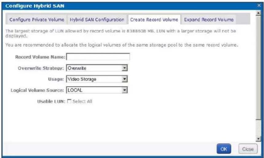
Figure 6.8 Create Record Volume
- Enter the RecordVolume Name in text field.
- Select Overwrite Strategyas Overwrite or Do Not Overwrite.
● Overwrite: Once the record volume is full, videos can still write into it by covering the earliest videos.
- Do Not Overwrite: Once the record volume is full, videos cannot be written in it
- Select Record Volume Usage as Video Storage or Picture Storage.
- If you want to create record volume based on local HDD or array, select LogicalVolumeSources Local. If you want to create it based on IP SAN, select LUNsourceas IP SAN.
- Select one or more UsableLUN.

If the capacity of private volume 1 and private volume 2 are both larger than 50 GB, maximum capacity of each LUN of record volume is 8 TB.
- Click OK to create the record volume. The created record volumes are listed in Record Volume list.
6.2.3.2 Clearing, Modifying, and Deleting RecordVolume
Purpose:
The created record volumes are listed in Record Volume list. You can clear videos saved in it, modify its configuration, and delete it.
Table 6.3 Icon Description
| Icon Name Description | |
| Clear data You can clear videos saved in the record volume. | |
| Modify You can modify record volume name, usage, and data overlay strategy. | |
| Delete You can delete the record volume. Data saved in it is removed. | |
| NOTE Do not delete record volume when linked encoder is recording. |
If a record volume consists of two or more LUNs, you can delete one of them according to following steps:
Steps
- Click the record volume name.
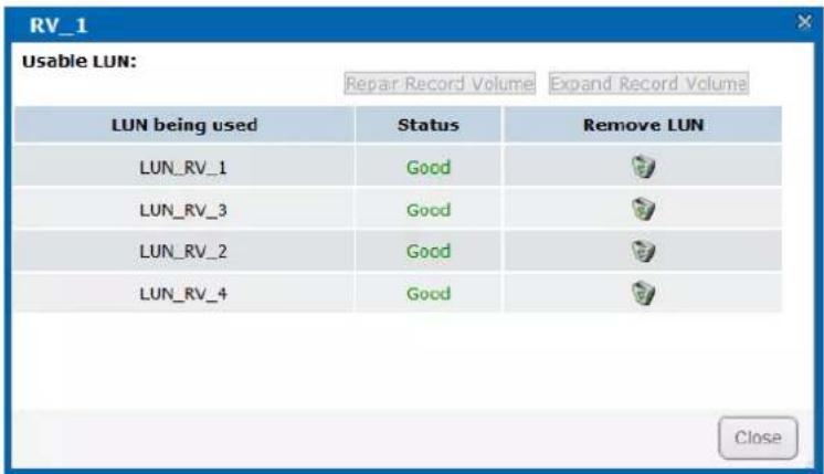
Figure 6.9 LUNs
-
Click of the LUN you want to delete.
-
Enter yes or YESintext field to delete it. After it is deleted, data saved in the LUN is deleted and the LUN status is Free.
6.2.3.3 Extending
Purpose:
When the record volume capacity is insufficient, you can use the free LUNs to extend it.
Steps:
- Click ExtendRecordVolume menu.
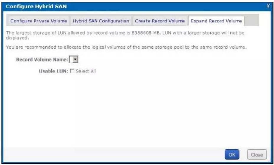
Figure 6. 10 Extend Record Volume
- Select the record volume you want to extend in RecordVolumeName dropdown list.
- Select the UsableLUNused to extend.
- Click OK to start extending.
6.3 Backup and Restoring
Purpose:
The chapter introduces the video backup and HYBRID SAN restoring steps.
Step:
Click BackupandRestorebutton in upper right corner.
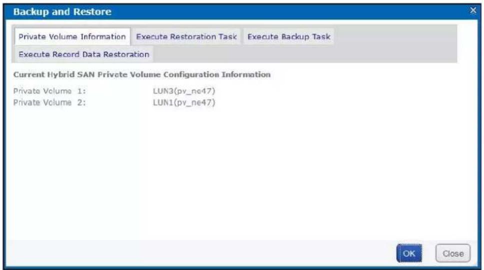
Figure 6.11 Back and Restore
6.3.1 Viewing Private Volume Information
Step:
Click Private volume information menu to enter Private Volume information interface. LUNs making up private volume 1 and private volume 2 are listed.
6.3.2 Restoring
Purpose:
When error occurs to HYBRID SAN, restoring HYBRID SAN can recover it. Restoring may cause data loss, so you need to contact us for professional help. We are not responsible for error caused by unprofessional operation.
Step:
Click ExecuteRestorationTaskmenu to enter Restore interface.
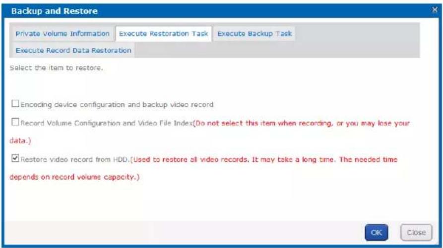
Figure 6. 12 Restore
6.3.3 Backup
Purpose:
The storage system backs up the index of all videos every hour. You can manually back up all videos' index according to following steps. The backed up index is saved in database.

The function backs up video index instead of videos.
Steps:
- Click ExecuteBackup Tasktab.
- Click OK to start backing up.
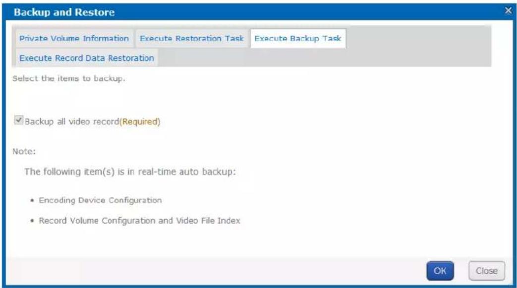
Figure 6.13 Backup
6.3.4 Recovering Video Data
Purpose:
If you reset HYBRID SAN, deleted record volume, or cleared record volume by mistake, you can contact us for professional help, we would help you to recover these data. We are not responsible for error caused by unprofessional operation.
Step:
Click ExecuteRecordData Restoration tab.
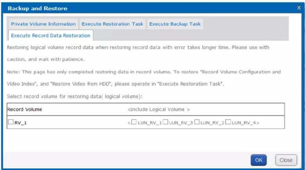
Figure 6.14 Record Data Recovery
6.4 N+1 Management
Purpose:
A storage system whose HYBRID SAN service has started can serve as a backup HYBRID SAN for other HYBRID SAN s. When one or more master HYBRID SAN s fail, the backup HYBRID SAN would record the videos from encoders. Master HYBRID SAN error includes network error, private volumes damaged, database error, and HYBRID SAN service error. After the master HYBRID SAN s recovers to normal, backup HYBRID SAN would upload videos back to master HYBRID SAN s.
Beforeyou start:
Start HYBRID SAN service in both master HYBRID SAN and backup HYBRID SAN.
Step:
Click N+1 in navigation bar and choose N+1 to enter HYBRID SAN interface.
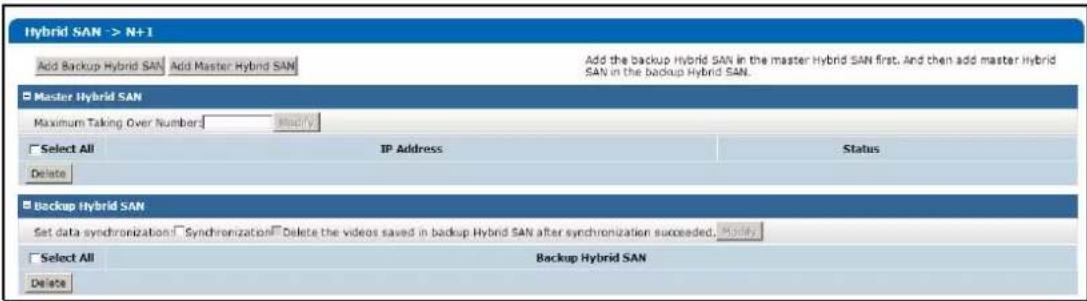
Figure 6. 15 N+1 Management

- Log into master HYBRID SAN and add backup HYBRID SAN for master HYBRID SAN first. And then Log into backup HYBRID SAN and add master HYBRID SAN for backup HYBRID SAN.
● A storage system can be either backup HYBRID SAN or master HYBRID SAN. - Ensure the system time of backup HYBRID SAN and master HYBRID SAN are the same. For detailed steps of modifying system time, refer to Chapter8.3 Time.
● Once master HYBRID SAN can only link to one backup HYBRID SAN
It is not recommended that encoding devices added in backup HYBRID SAN have duplicate name.
6.4.1 Adding Backup HYBRIDSAN
Purpose:
Add backup HYBRID SAN in master HYBRID SAN first.
Beforeyou start:
Log into master HYBRID SAN and enter N+1 Management interface.
Steps:
- Click the Add Backup HYBRIDSAN button.
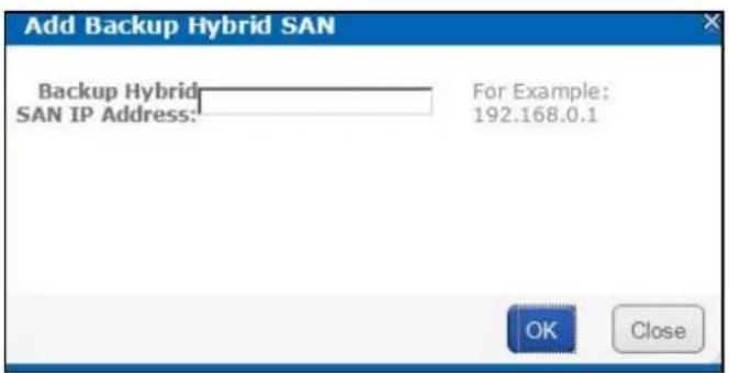
Figure 6. 16 Add Backup HYBRID SAN
- Enter the backup HYBRID SAN IP address.
- Click OK to add.
- Optionally, you can check the checkboxes of Synchronization and Delete the videos saved in backup HYBRIDSAN after synchronization succeeded, and click Modify to enable them.
Synchronization: Once master HYBRID SAN recovers to normal, backup HYBRID SAN uploads the videos back to master HYBRID SAN.
Delete the videos saved in backup HYBRIDSAN after synchronization succeeded: Delete the videos in backup HYBRID SAN once they are uploaded to master HYBRID SAN.

Figure 6.17 Backup HYBRID SAN
6.4.2 Deleting Backup HYBRIDSAN
Steps:
- Check the checkbox of backup HYBRID SAN you want to delete.
- Click the Delete button and click OKin confirmation dialog box.
6.4.3 Adding Master HYBRIDSAN
Before you start:
- Log into backup HYBRID SAN and enter N+1 Management interface.
- Add the same encoding devices in backup HYBRID SAN, which have been added in master HYBRID SAN. For details, refer to chapter 7.3.2 Adding Encoding Device. Ensure the name of encoding devices from different backup HYBRID SAN's varies from each other.
- Delete the added encoding devices in step 2.
- Add schedules for encoding devices in backup HYBRID SAN the same as schedule in master HYBRID SAN.
Steps:
- Click the Add Master HYBRIDSAN button.
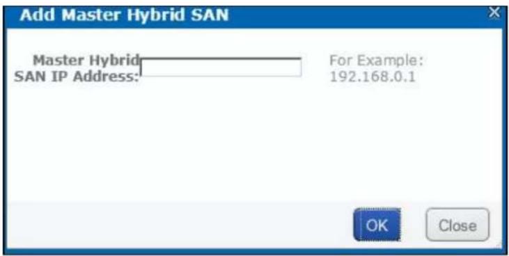
Figure 6. 18 Add Master HYBRID SAN
- Enter master HYBRID SAN IP address.
- Click OK to add. The added master HYBRID SAN is listed in HYBRID SAN master list
- Enter Maximum TakingOver Number and click Modify. If maximum taken-over master HYBRID SAN is 4 and 7 master HYBRID SAN s are added, when 5 master HYBRID SAN s are abnormal, the backup HYBRID SAN would take over the first added 4 master HYBRID SAN s. After one or more of the 4 HYBRID SAN s recovers, other master HYBRID SAN s would be taken over.

The max. taken-over number cannot be more than 10. If input 0 or input nothing, system regards it as 10.
Table 6.4 Backup HYBRID SAN Status
| Backup HYBRID SAN Status | Description |
| Standby | When master HYBRID SAN is normal, backup HYBRID SAN is standby. |
| Working | When master HYBRID SAN is abnormal, backup HYBRID SAN takes over the tasks.Now backup HYBRID SAN status is working and master HYBRID SAN status is taken-over. When master HYBRID SAN recovers, backup HYBRID SAN recovers to standby. |
Chapter 7 HYBRIDSAN Sub-System
Purpose:
You can configure the parameters for HYBRID SAN sub-system.
Table 7.1 Module Description
| Module Description | |
| Information | Encoding device, record schedule, and record volume information are listed. |
| Encoding Device | You can add and manage encoding devices, adjust HYBRID SAN sub-system time, count remaining recoding capacity, and analyze video loss. |
| Preview and Record | You can view encoding device status and live view image, and start and stop manual record of one or more encoding devices. |
| Strategy and Alarm | You can configure recording schedule, create uploading task and schedule, and configure alarm parameter. |
| Download and play | You can search, archive, backup, lock, play, and download recorded videos. |
| User Management | You can switch system language and edit display rows in each page. |
| System Config | You can configure system alarms and view HYBRID SAN version. |
| Log Management | Log helps you figure out HYBRID SAN history actions. You can search, export, and clear logs. |
Key Words:
Information, Encoding Device, Preview and Record, Strategy and Alarm, Download and play, User Management, System Config, Log Management
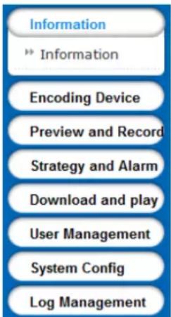
Figure 7.2 HYBRID SAN Sub-System
7.1 Accessby Web Browser
Steps:
- Open web browser.
- Input the storage system IP address (https://10.254.254.254:2004) in Web browser address bar.
- Press Enter. Then login interface appears.
- Enter Password of HYBRID SAN sub-system and click Loginto log in.
STRONGPASSWORDRECOMMENDED—Wehighlyrecommend you create a strong password of your own choosing(Using a minimum of 8 characters, including at least three of the following categories: upper
caseletters, lower caseletters, numbers, and special characters.) in order to increase the security of your product.
And we recommend you reset your password regularly, especially in the high security system, resetting the password monthly or weekly can better protect your product.
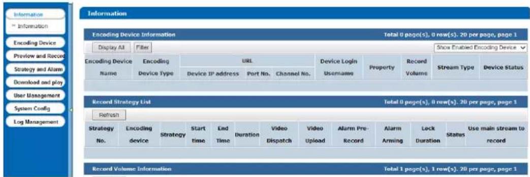
Figure 7.3 HYBRID SAN Sub-System
7.2 Information
Purpose:
Encoding device, record schedule, and record volume information are listed.
Step:
Click Information in navigation bar.
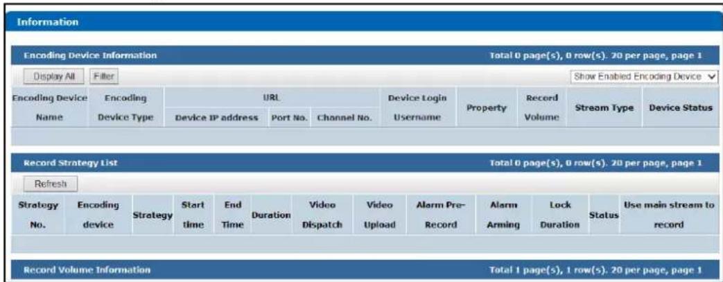
Figure 7.4 Information
Table 7.2 Status Description
| Status Description | |
| Free | Connection is normal and it is recording. |
| No video input | It appears when encoding device amount reaches the limit or HYBRID SAN is rebooting. |
| Recording Encoding device is recording. | |
| Password or user name error | Incorrect user name or password for encoding device. |
| Not load | When HYBRID SAN starts, loading encoding device failed. |
| Unknown HYBRID SAN is error. | |
| Not connected | Failed to get stream for encoding device. |
| Recording... Archiving... | Encoding device is recording and archiving. |
| Recording... Uploading... | Encoding device is recording and receiving videos from front-end devices. |
| Archiving | Encoding device isn’t recording, but is archiving. |
| Uploading | Encoding device isn’t recording, but is receiving videos from cameras. |
7.3 Encoding Device
Purpose:
You can add and manage encoding devices, adjust HYBRID SAN sub-system time, count remaining recoding capacity, and analyze video loss.
Step:
Click EncodingDevicein navigation bar.
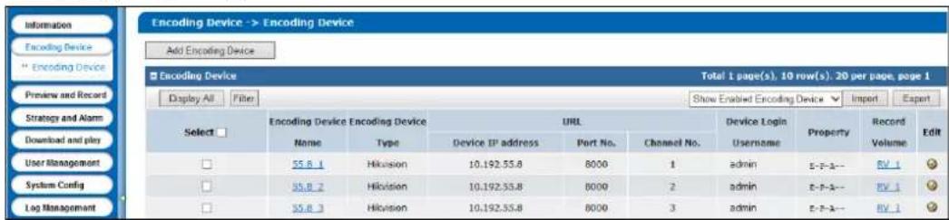
Figure 7.5 Device Management
7.3.2 Adding Encoding Device
Steps:
- Click Add Encoding Device.
- Enter Encoding Device Name.
- According to encoding device acutal parameters, select EncodingDeviceType, enter IP/Host, Port, Channel, Login user, and Password.
- Optionally, you can enable stream media server by checking the checkbox of EnableSMS(Stream Media System), inputting IP address:port(e.g., 192.168.0.2:554) in SMS, and select URLMark and Transmission Method.
- Optionally, you can enable other function according to your needs.
➢ Enable streaming according to needs: The storage system releases occupied bandwidth, when no
stream requirement for the encoding device. If selected, the encoding device Attribute marks as P.
ANR(Automatic Network Replenishment): When the storage system disconnects with the encoding device, the encoding device records video and stores in its own storage device, like SD card. Once connection recovers, encoding device sends the video to the storage system. If selected, the encoding device Attribute marks as T.
Enablesub-streamto preview and record: If selected, when you preview and record via sub-stream, it takes lower bandwidth. But sub-stream video quality and bitrate is lower than main stream. And the encoding device Attribute would mark as S. If record strategy exists, HYBRID SAN gets stream according to strategy.
EnableArming: If selected, when alarm occurs to encoding device, HYBRID SAN can trigger alarm record. And the encoding device Attribute would mark as A.
-
Select related record volume in Link to RecordVolume.
-
Click OK and click OK in confirmation dialog box to add the encoding device.
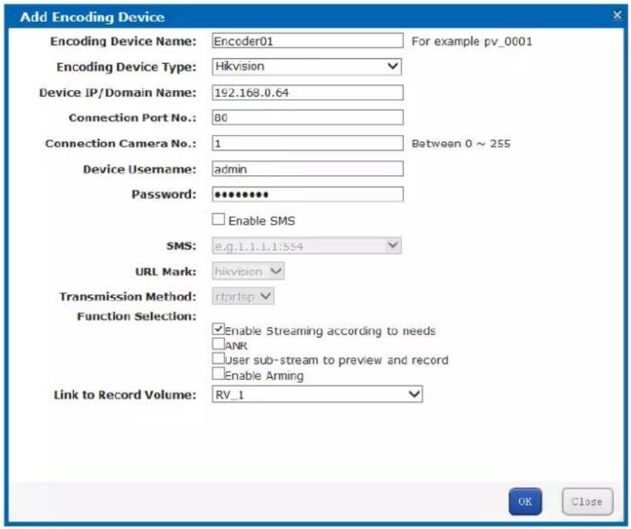
Figure 7.6 Add Encoding Device

Repeat above steps to add more encoding devices. Up to 1024 encoding devices can be added.
If the encoding device you add isn't in the List of Compatible of Encoding Device, the Attribute would mark as B. You can ask technical support for the List of Compatible of Encoding Device.
7.3.3 Modifying and Deleting
Steps:
● To delete encoding devices, do following steps:
- Check the checkbox of encoding device you want to delete.
- Click Delete encoding device.
● To modify encoding device parameters, do following steps:
1. Click √ of encoding device you want to modify.
2. Edit the parameters you want to modify.
3. Click OK and click OK in confirmation dialog box to save the settings.
● To modify linked record volume, do following steps:
1. Check the checkbox encoding device you want to modify.
2. Select the target record volume in the dropdown list.
7.3.4 Exporting and Importing EncodingDevice
Purpose:
For the purpose of modifying a large number of encoding device in batch, you can export them, modify their parameters, and import them back to HYBRID SAN sub-system.
Steps:
● To export encoding devices, do following steps:
- Click and click OK in confirmation dialog box.
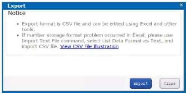
Figure 7.7 Export
- Select file saving path and click OK to save it.

The exported file is a .csv file. You can view and edit it via Microsoft Excel. The content of exported file is shown in Figure 7.8 ExportedFile.

Figure 7.8 Exported File
● To import encoding devices, do following steps:
- Click

- Click Browse and select the target file.
- Optionally, you can select the Operation Options.
Update Duplicate Device: When the contents of HOST and CHANNEL column of several encoding devices are the same, HYBRID SAN judges them as duplicate encoding device. If it is selected, HYBRID SAN would add all of the duplicate encoding devices and update the previous encoding devices' parameters. Or duplicated wouldn't be added.
Update encoding device with the same name: If selected, when encoding devices in HYBRID SAN sub-system and importing file share the same name, once imported, the encoding devices in importing file would replace the one in HYBRID SAN sub-system.
Auto link record volume: If selected, when encoding devices in importing file have no linked record volume, once imported they would link to the first record volume in HYBRID SAN sub-system.
Auto Rename: If selected, when duplicated name exists during add and modifying, the name of added encoding devices would be renamed as "previousname_1".
- Click OK and click OK in confirmation dialog box to import. The encoding device list would be updated according to imported file.
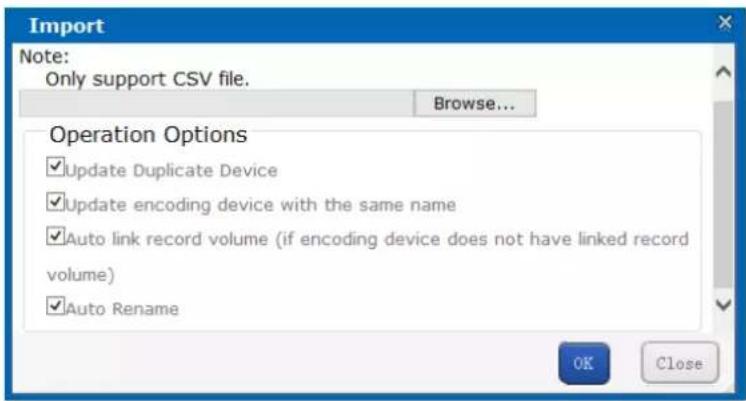
Figure 7.9 Import
7.4 Previewing and Recording
Purpose:
Do following steps to start or stop recording manually.
Steps:
Click Preview and Recordin navigation bar.
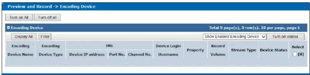
Figure 7. 10 Preview and Record
● To start or stop manual recording for specified encoding devices, do following steps:
1. Check the checkboxes of encoding devices you want to start manual record.
2. Click Turnon videosto start recording. And you can click turn off videosto stop recording.
● To start or stop manual recording for all encoding devices, do following step:
Click Turnon All to start recording for all. And you can click Turnoff All to stop recording for all.

If the encoding device is recording according to record schedule, click Stop recording or All stop wouldn't stop recording, for record schedule would start recording again. For schedule details, refer to 7.5StrategyandAlarm.
7.5 Strategy and Alarm
Purpose:
You can configure recording schedule, create uploading task and schedule, and configure alarm parameter.
Step:
Click Strategy and Alarm in navigation bar.
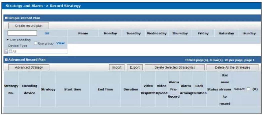
Figure 7. 11 Strategy and Alarm
7.5.1 Record Plan
Purpose:
Set the record plan, and then the encoding devices automatically starts and stops recording according to the configured plan.
Step:
Click RecordStrategyin navigation bar.
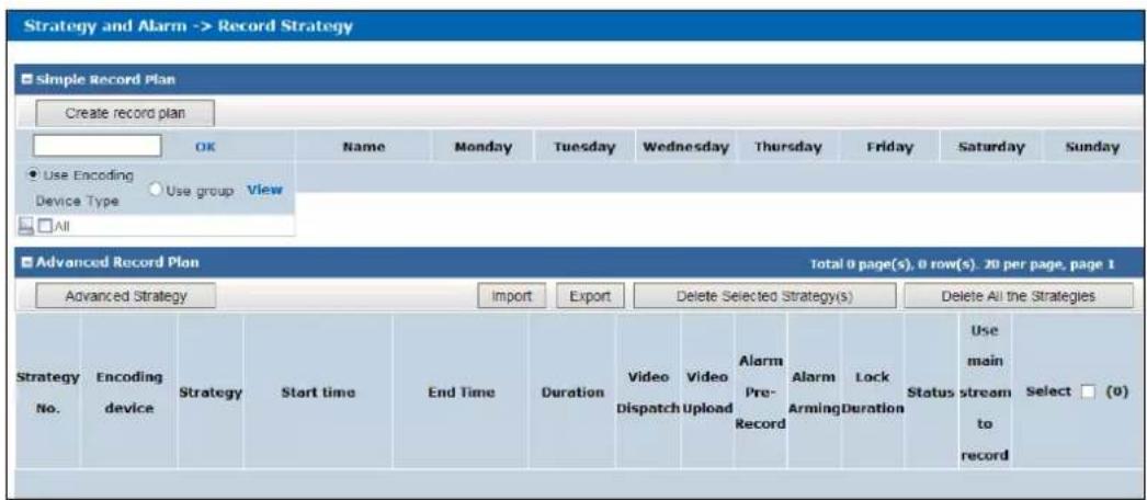
Figure 7. 12 Record Strategy

It is recommended to configure either simple record plan or advanced record plan.
7.5.1.2 Simple RecordPlan
Purpose:
Set the simple record plan, and then the specified encoding devices automatically start/stop recording according to the configured plan.
Steps:
-
Click Createrecord plan.
-
Enter in the encoding device name and click OK to select the encoding device. Repeat the step to add more. Or select encoding devices or groups in the list.
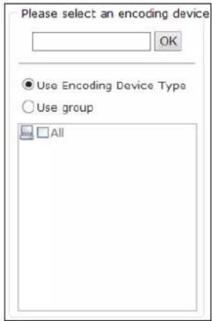
Figure 7.13 Select Encoding Devices
- Select the Date on which you want to set schedule.

Figure 7.14 Date
- In Recordmode, to schedule an all-day recording, check the checkbox of Whole-day Video. Or you can select the one or more time segments to set start time and end time.

Up to 8 periods can be configured for each day. And the time periods can't be overlapped with each other.
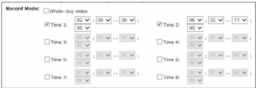
Figure 7.15 Record
- Optionally, you can select one or more Dispatchoptions.
Disabled by Default: If selected, schedule status is Stopped. And encoding device would not start recording. Other Schedule options wouldn't take effective.
Not executerecord dispatch: If selected, encoding device wouldn't start recording. Other Schedule options
wouldn't take effective.
Copyback: If selected and uploading schedule exists, the camera video would upload to HYBRID SAN. For details of configuring uploading schedule, refer to chapter 7.5.2.3 AddingUpload.
➢ Disable alarm pre-record: Pre-record refers to the time you set to record before the scheduled time or event. If selected, pre-record is turned off.
Disablealarmarming: If selected, when encoding device is error, HYBRID SAN wouldn't alarm.
Lock:If selected, you need to set locking time as a specified duration or keep locking. During locking time, videos wouldn't be overlapped. Locking time must be longer than duration time.
Usesubstream to record: If selected, encoding device records via sub-stream instead of main stream.
7.5.1.3 Advanced Record Plan
Purpose:
By setting advanced record plan, you can specify the start recording time and recording duration for designated.
Steps:
-
Click AdvancedStrategy.
-
Enter in the encoding device name and click OK to select the encoding device. Repeat the step to add more. Or select encoding devices or groups in the list.
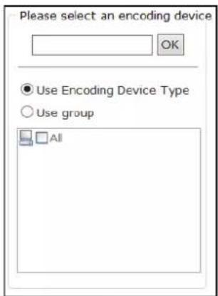
Figure 7. 16 Select Encoding Devices
- Select Start time by Instant Recordingor Preset Time.
➢ Instant Recording: Starts recording once schedule is added.
➢ Presetime: Starts recording at the set time.
- Select Duration unit as Week, Day, Hour, Minute, or Second and enter number.
Duration: Keeps recording during the time.

Figure 7. 17 Start Time and Duration Time
-
Optionally, you can select one or more Dispatchoptions. For details, refer to step5 of 7.5.1.2 SimpleRecord Plan.
-
Select UseStrategy and set the end time.

If Schedule is set as hour, minute, or customized, locking in schedule options is not selectable.
- Click OK to save the schedule. Then before the end time, the selected encoding devices would repeatedly start recording at set start time and stop recording till the duration time.
7.5.1.4 Exporting and Importing Advanced RecordPlan
Purpose:
For the purpose of managing advanced schedules in batch, you can export them, modify their parameters, and import them back to HYBRID SAN sub-system.
Step:
For detailed steps, you can refer to chapter 7.3.4 Exporting and Importing EncodingDevice.
7.5.2 Upload Strategy
Purpose:
When videos in HYBRID SAN lost, and the lost videos exist in encoding devices. You can upload the videos back to HYBRID SAN.
Step:
Click Strategy and Alarm in navigation bar and choose Upload Strategy.
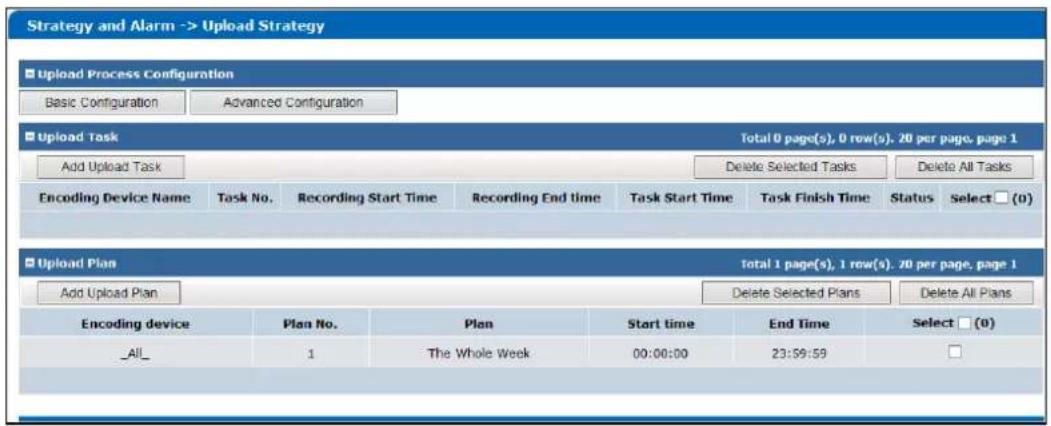
Figure 7. 18 Upload Strategy
7.5.2.1 BasicSettings
Steps:
-
Click BasicConfiguration.
-
Enter Detection Start Time, Detection End Time, Max. CameraNumber, and Max. Uploading Camerafor One DVR.
Detection Window Start Time: Start time of detecting uploading.
Detection Window End Time: End time of detecting uploading. Videos ranges from detection start time to end time would be uploaded.
UploadChannelmaxlimit: The maximum cameras that could upload simultaneously.
SingleDVRUploadingMaxLimit: The maximum cameras in a DVR that could upload simultaneously.
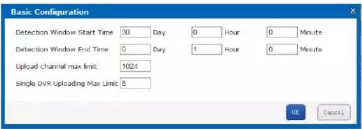
Figure 7. 19 Basic Configuration
7.5.2.2 Adding Uploading Tasks
Purpose:
When videos in HYBRID SAN lost, and the lost videos exist in encoding devices. You can upload the videos back to HYBRID SAN by adding uploading tasks.
Steps:
-
Click Add Upload Task.
-
Enter the encoding device name and click OK to select the encoding device. Repeat the step to add more. Or select encoding devices or groups in the list.
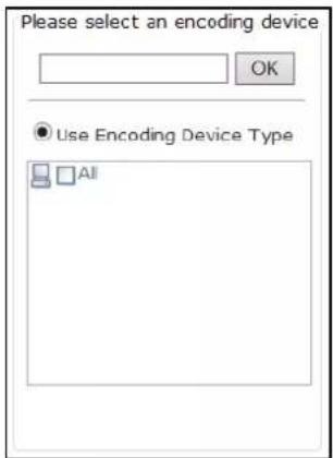
Figure 7. 20 Select Encoding Devices
- Set the Video Start time and Video Endtime of video you want to upload.
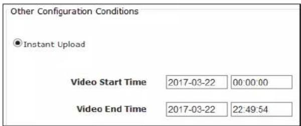
Figure 7.21 Add Uploading Tasks
- Click OK to add the task. Then if encoding device contains the video, it starts uploading the video to HYBRID SAN.
7.5.2.3 Adding Upload Plan
Purpose:
Uploading schedule can judge whether video loss happens during record schedule. Configure the uploading schedule to upload the videos saved in encoding devices back to HYBRID SAN.
Beforeyou start:
Ensure pulling back data from encoding device in schedule options is selected when configuring basic or advanced schedule. For detailed steps, refer to chapter 7.5.1.2 SimpleRecordPlan and chapter 7.5.1.3 Advanced.
Steps:
-
Click Add Upload Plan.
-
Enter the encoding device name and click OK to select the encoding device. Repeat the step to add more. Or select encoding devices or groups in the list.
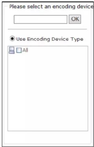
Figure 7.22 Select Encoding Devices
- Select the date on which you want to set schedule.
- In Upload mode, to schedule an all-day uploading, check the checkbox of All-day Upload.
Or you can select the one or more time segments to set start time and end time.

Up to 8 periods can be configured for each day. And the time periods can't be overlapped with each other.
- Click OK to add the schedule. Then selected encoding devices only upload videos during the set data and time segments.
7.5.3 Alarm
Purpose:
You can set the recording time for alarm events.
Beforeyou start:
Enable alarm events you want to pay attention in encoding devices first. For details, refer to user manual of encoding device.
Steps:
- Click Strategy and Alarm in navigation bar and choose Alarm.
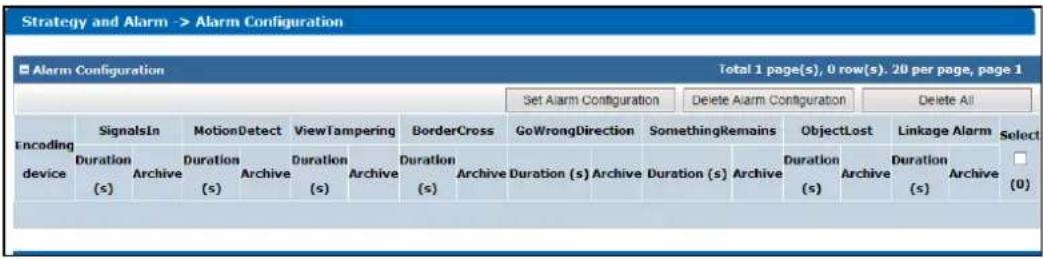
Figure 6. 23 Alarm
- Click Set Alarm Configuration.
- Enter the encoding device name and click OK to select the encoding device. Repeat the step to add more. Or select encoding devices or groups in the list.
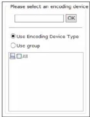
Figure 6.24 Select Encoding Devices
- Enter Trigger Recording (Archive) Duration for alarm types you want to pay attention. Valid Duration ranges from 5 to 9999. Then when an alarm occurs, HYBRID SAN starts recording for the set Duration.
The supported alarm types include Signal Source, Motion Detection, Video Tampering, Perimeter Cross, Wrong Direction, Unattended Baggage, and Object Loss.
- Optionally, you can check the checkbox of Archive of alarm types. Then the alarm videos can be viewed in Archive Search interface.
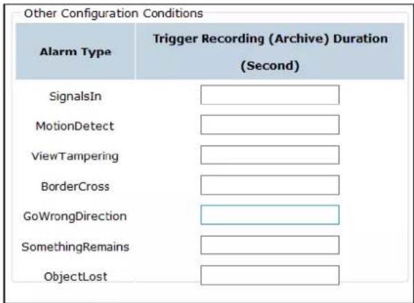
Figure 6. 25 Other Configurations
- Click OK to save the settings.
7.6 Playing and Downloading
Purpose:
You can search, archive, backup, lock, play, and download recorded videos.
Step:
Click Download and Playin navigation bar.
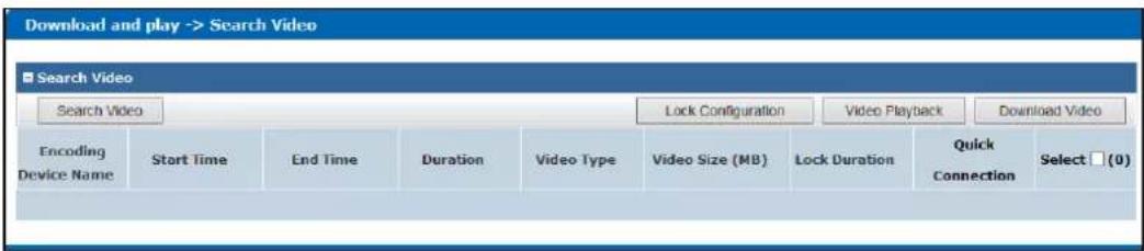
Figure 7.26 Download and Play
7.6.1 SearchingVideo
Steps:
- Click SearchVideo.
- Enter the encoding device name and click OK to select the encoding device. Repeat the step to add more. Or select encoding devices or groups in the list.
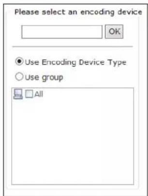
Figure 7.27 Select Encoding Devices
- Specify the search conditions including Start Time, End Time, Record Type, Search Type, and Display locktime (whether it is a locked video).
- Click OK to start search. And the videos meet the search conditions would be listed.
7.6.2 LockingVideos
Purpose:
The locked videos will not be overlapped by other videos.
Beforeyou start:
Search videos first.
Steps:
- Check the checkboxes of videos you want to lock. Not more than 100 videos can be selected.
-
Click LockConfiguration.
-
Select lock mode as Unlock, Locklast, or Locktime.
Unlock:If selected, the locked video would be unlocked.
AlwaysLocked: If selected, the video is locked permanently.
LockDuration: If selected, you need to set the locking time. Then the video would be locked from the video start time for the set time.
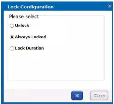
Figure 7.28 Lock Mode
7.6.3 Playing Videos
Purpose:
Play back videos to view the history image.
Beforeyou start:
- Search videos first.
-
Add IP address of HYBRID SAN to web browser trusted sites and enable all of ActiveX controls and plug-ins.
-
Enter Trusted Sites menu.
Tools > Internet Options > Security > Trusted Sites
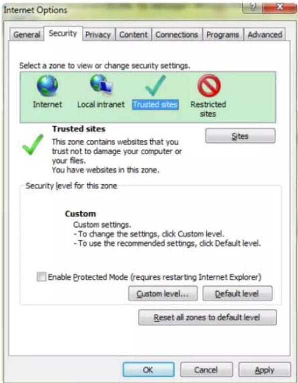
Figure 7. 29 Trusted Sites
- Click Sites
button, enter https://IP addressof HYBRIDSAN, click Add, and click Closeto go
back to upper menu. - Click Custom level... button, enable all of ActiveX controls and plug-ins, click OK to save and go back to upper menu.
- Click OK to save the settings.
7.6.3.2 Whole Video Playback
Purpose:
Play the original video.
Steps:
- Check the checkboxes of videos you want to play. Not more than 16 videos can be selected.
- Click Video Playback.And another window pops up. You can view the playback image.
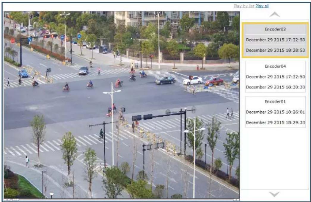
Figure 7. 30 Playback Window
- You can play all selected videos by clicking PlayAll in upper-right corner.
7.6.4 Downloading Videos
Purpose:
Save the videos to computer by downloading them.
Beforeyou start:
Search videos first.
7.6.4.1 One-KeyDownloading
Step:
Click ↓ button and select the saving path to save a single video.
7.6.4.2 Block Downloading
Steps:
Click button and click CompleteDownload to download.
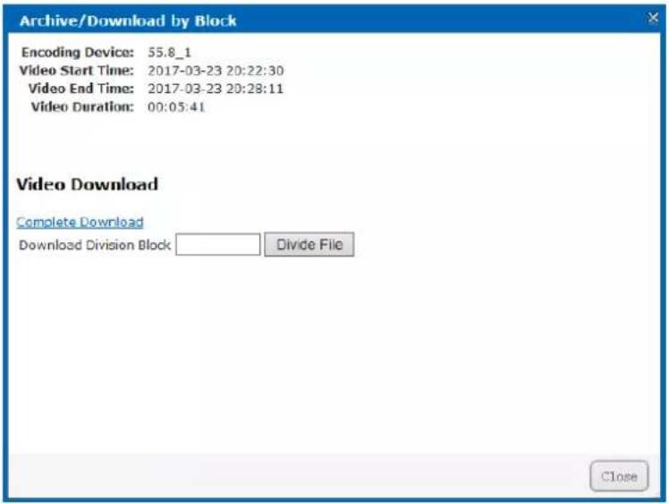
Figure 7. 31 Segment Downloading
7.6.4.3 BatchDowloading
Steps:
- Check the checkboxes of videos you want to download.
- Click Download button to pop up batch downloading interface.
- Click button to select saving path.
- Select downloading mode as By signle-taskor By multi-task.
Bysingle-task:Download one video at a time.
By multi-task: Download several videos simultaneously. The maximum downloading video amount is Max. number of tasks whose valid range is from 1 to 5.
- Click Start to start downloading. You can click Stop to stop downloading.
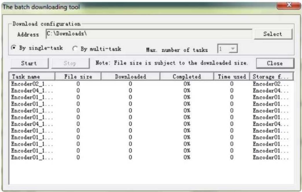
Figure 7. 32 Batch Downloading
7.7 User
Purpose:
You can switch system language and edit display rows in each page.
Steps:
- Click UserManagementin navigation bar.
- To modify Interface language, select language in the dropdown list.
- To modify the display rows in each page, select number in the dropdown list of Number of table rows shown in eachpage.
- Click UploadConfiguration to save the changes.
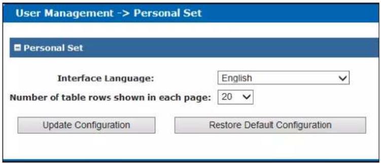
Figure 7.33 User
7.8 SystemConfiguration
Purpose:
You can configure system alarms and view HYBRID SAN version.
Step:
Click SystemConfigin navigation bar.
7.8.1 SystemAlarm
Purpose:
You can set linkage actions for alarm type, specify alarm type for alarm events, and turn on or turn off status alarm.
Steps:
- Click Systemin navigation bar and choose SystemAlarm to enter System Alarm interface.
- Alarm type includes Info (Information), Warning, Error, and Fatal. Specify 3 linkage actions for the 4 alarm types.
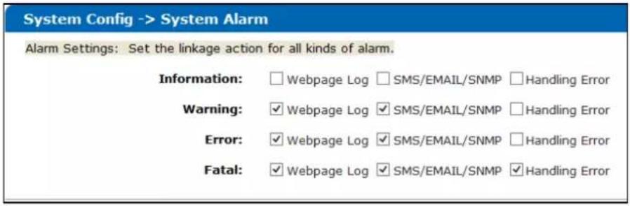
Figure 7. 34 Alarm Setting
- Specify alarm type for alarm events.
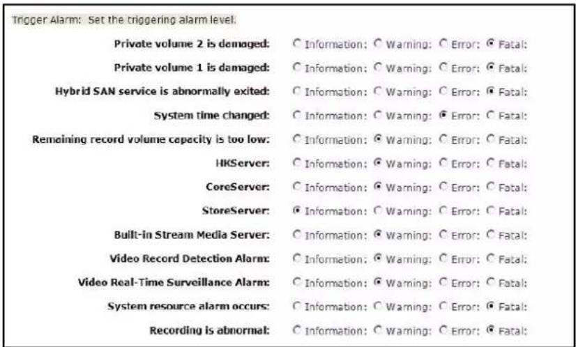
Figure 7. 35 Alarm Events
- Turn on or turn off status alarm.
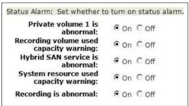
Figure 7. 36 Status Alarm
- Click to save the settings.
7.8.2 HYBRIDSAN Version
Purpose:
You can view HYBRID SAN version, HYBRID SAN library version, and HYBRID SAN other version.
Step:
Click SystemConfigin navigation bar and choose Version.
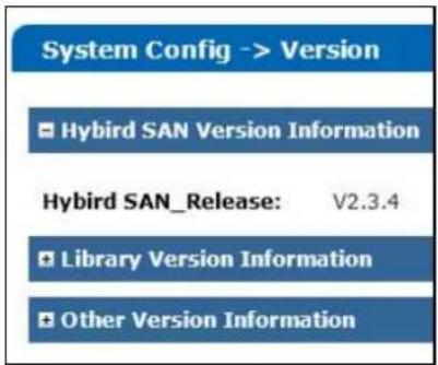
Figure 7. 37 HYBRID SAN Version
7.9 LogManagement
Purpose:
Log helps you figure out HYBRID SAN history actions. You can search, export, and clear logs.
Step:
Click LogManagementin navigation bar to enter Log Management interface.
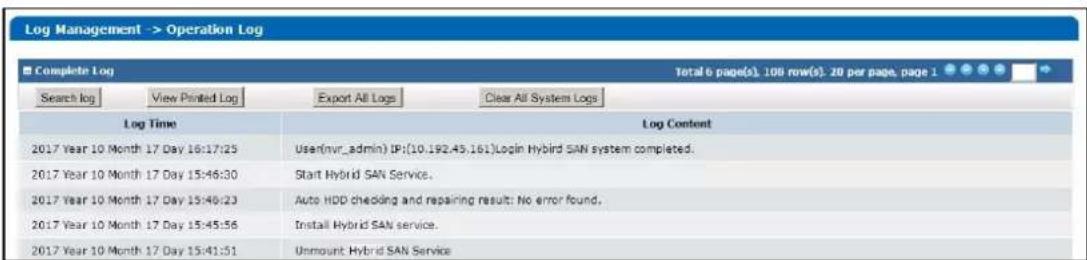
Figure 7. 38 Log Management
7.9.1 Searching Log
Steps:
- Click Searchlog.
- Specify the search condition including Logtype, Starttime, Endtime, and Including Characters.
- Click OK to start search. The matched logs would be listed.
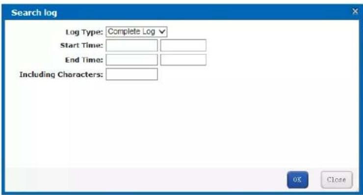
Figure 7. 39 Log Search
7.9.2 Exporting Log
Purpose:
You can export the listed logs to local HDD.
Beforeyou start:
Search the logs you want to export.
Step:
Click ExportAll Logs and choose the saving path to save it.

The exported logs are integrated in a .csv file.
7.9.3 Clearing Log
Step:
Click ClearAll SystemLogsand click OK in popup confirmation dialog box to clear all logs saved in HYBRID SAN sub-system.
Chapter 8 System
Purpose:
You can configure network parameters, alarm triggered action, system time, modify system password, and so forth.
Table 8.1 Module Description
| Module Description | |
| Network | You can:Modify the configuration of management network interface and data network interfaces.Bond data network interfaces.Remotely access the storage system via a specified gateway.Edit DNS server IP address, bond mode, and network work speed. |
| Alarm | You can:Send the storage system alarms to client via e-mail or SNMP manager. |
| Time | You can:Manually or automatically adjust system time. |
| Power Supply | You can:View UPS mode.Modify UPS power-off time.Modify supported UPS manufacturer. |
| Management Tool | You can:Modify user password.Configure SMTP parameters.Test network communication between the storage system and a specified IP address.Update the storage system.View service status. |
Keywords:
Network, Alarm, Time, Power Supply, Tool
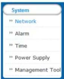
Figure 8.2 System
8.1 Network
Purpose:
The storage system provides one management network interface and two data network interfaces. The management network interface is designed for configuring the data network interface and device maintenance.
The data network interfaces are used to transmit data.
Step:
Click Systemin navigation bar and choose Network.
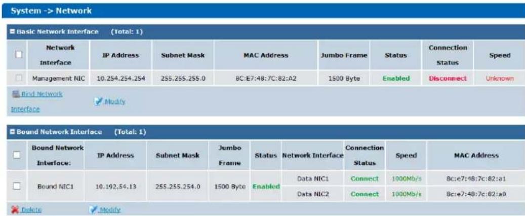
Figure 8.3 Network
8.1.1 Modifying DataNetwork Interface
Steps:
- Check the checkbox of data network interface.
- Click Modify in Basic Network Interface list.
- Enter the new IP Address and Subnet Mask and select MTU in dropdown list.
MTU (Maximum Transmission Unit): Select MTU as larger than 1500 byte for the purpose of improving transmission performance.
- Click OK to save the settings.
8.1.2 Binding Network Interfaces
Purpose:
When transmitting data via a single data network interface, once the data network interface fails, data transmission stops. By bonding multiple data network interfaces into one, they can share one IP address, thus to balance network load and create redundant links. When transmitting data via a bound network interface, once a data network interface fails, other data network interfaces take over the transmission task.

● The management network interface does not support bond.
● The IP address of bound network interface is the same as the first data network interface.
Beforeyou start:
Connect all data network interfaces to network via network cables.
8.1.2.1 Creating Bond
Steps:
- Check the checkboxes of data network interfaces in Basic Network Interface list.
- Click Bind Network Interface and click OKin confirmation dialog box.

Figure 8.4 Bound Network Interface Information
8.1.2.2 Deleting Bond
Steps:
- Check the bound network interface checkbox.
- Click and click OKin confirmation dialog box. Then the bound network interface is recovered to several data network interfaces.
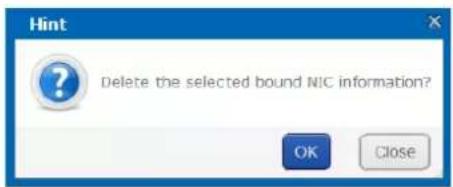
Figure 8.5 Confirmation Dialog Box
8.1.2.3 Modifying Bonding Mode
For detailed information and steps, refer to section8.1.5.2BindingMode.
8.1.3 Adding Route
Purpose:
By default, the route is empty, clients in different network segment access the storage system via the default gateway. If you want to access the storage system via a specified gateway, add route here.
Steps:
- Click Add Routelinfo in Custom Route Information list.
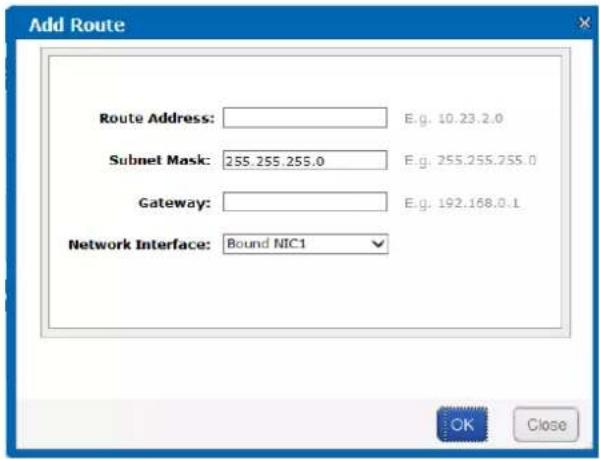
Figure 8.6 Add Route
- Input Route IP Address, Subnet Mask, and Default Gateway. The client server within Route IP address can access the storage system via the Default Gateway.
- Select Bound data Network Interface in the dropdown list.
- Click OK to add the route. Thus the client server within 10.128.50.1 to 10.128.50.55 can access the storage system via the bound network interface 1 whose the gateway is 192.168.0.2.
8.1.4 MACand IP Bonding
Purpose:
Only client with the specified MAC address and IP address is allowed to get access to iSCSI HDD.
Steps:
- Click MAC&IPBonding.
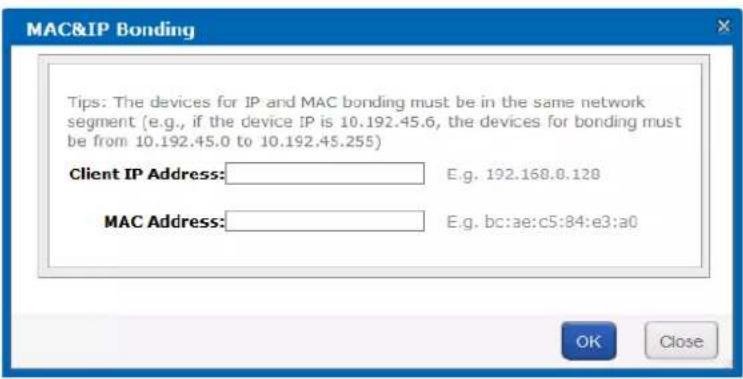
Figure 8.7 MAC&IP Bonding
- Input target Client IP Address and MACAddress.

Ensure the client IP is in the same network segment with the storage system.
- Click OK and click OK in pop up confirmation box to create bond.
8.1.5 Advanced Parameters
Purpose:
You can configure DNS server, bond mode, and network work speed parameters.
8.1.5.1 DNSServer
Purpose:
You are required to add DNS server IP address if you need to access external network.
Steps:
- Click Modify of Preferred DNSServer.
- Enter IP address in text field.
- Click OK and click OK in confirmation dialog box to save the settings.
Figure 8. 8 DNS Server
8.1.5.2 Binding Mode
Purpose:
The selection of bond mode is related to actual application and network situation. Up to seven types of bond modes are provided. For details, refer to Table8. 2 BondingMode Description.
Steps:
- Click Modify of NICBinding Mode.
- Select bond mode in dropdown list. Up to 7 bond modes are selectable.
- Click OK and click OK in confirmation dialog box to save the settings.
Figure 8. 9 NIC Binding Mode
Table 8.2 Bonding Mode Description
Bond Mode Description
- Definition:
All data network interfaces sends and receives data in turn.
When using the mode, it is recommended to apply protocols except TCP/IP.
- Advantage:
Round-robin
Load balance.
All data network interfaces are fully used.
There is no requirement about hardware like network switch.
- Disadvantage:
The order of received data is uncertain.
▶ Low network throughput.
- Definition: The default bond mode. Transmits data via a specified data network interface, other data network interfaces are standby. Only when the specified data network interface fails, another standby data network interface takes over
Active-Backup
| Bond Mode Description | |
| transmission task.Advantage:There is no requirement about hardware like network switch.Redundant network links.Disadvantage:Load balance isn't supported.Uses only one data network interface at a time. Other data network interfaces aren't fully used. | |
| XOR | Definition:The storage system can figure out the relationship between each data network interface and client MAC addresses. According to the relationship, the storage system transmits data to clients with corresponding data network interface. If the working data network interface fails, another data network interface takes over the task.It is recommended to use this mode in a local area network. However, if data is transmitted via network gateway, don't use the mode.Advantage:There is no requirement to hardware like network switch.Balance the load in the local area network within a network switch.Disadvantage:Loadbalance isn't supported in different local area network. |
| Broadcast | Definition: All the data network interfaces transmit the same data.Advantage:There is no requirement about hardware like network switch.Redundant network links.Data network interfaces are fully used.Disadvantage:Load balance isn't supported.Low data network interface usage. |
| 802.3ad | Definition: The storage system figures out the relationship between each data network interface and clients' MAC addresses according to Hash Algorithm. The storage system transmits data to client via corresponding data network interface.Advantage:Based on IEEE standard, devices in system can work efficiently if they are all 802.3ad mode.Load balance.Data network interfaces are fully used.Disadvantage:The storage system, network switch, and client server are all required to support 802.3ad mode. |
| Tlb | Definition: The storage system allocates output traffic to each data network interfaces, according to current load. And transmits data to clients via different data network interfaces. If the working data network interface fails, another data network interface takes over the task.● Advantage:➢ Data network interfaces are fully used.➢ Load balance when sending data.● Disadvantage:Loadbalance isn’t supported when receiving data. |
| Virtualization | ● Definition:➢ The storage system allocates input and output traffic to each data network interfaces, according to current load.➢ It is recommended to use the mode when sending and receiving data to multiple clients.● Advantage:➢ Data network interfaces are fully used.➢ Load balance in both sending and receiving data. |
8.1.5.3 Network Work Speed
Purpose:
It is the speed of all data network interfaces. The default network work speed is 100 Mb/s. It is recommended to set network work speed according to actual network situation.
Steps:
- Click Modify of Network Word Speed.
- Select Network Work Speed as 1000 Mb/s or 100 Mb/s.
- Click OK and click OK in confirmation dialog box to save the settings.
| Set Network Working Speed: | 1000 Mb/s | Modify |
8.2 Alarm
Purpose:
The storage system supports notifying you about the occurring alarms via e-mail and SMTP manager.
Steps:
Click Systemin navigation bar and choose Alarm to enter Network interface.
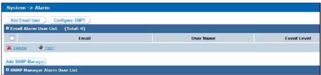
Figure 8. 10 Alarm
8.2.1 Alarm Type
Purpose:
The Table8. 3 Alarm TypeDescriptiondescribes the supported alarm types and corresponding event level. E-mail
and SNMP manager support notifying you about the alarm types in Table8.3.
Table 8.3 Alarm Type Description
| Module Alarm | Type Event Level | |
| Power supply | Controller power supply error Serious | |
| Storage enclosure power supply error | Serious | |
| Temperature | Temperature is too high Warning | |
| Temperature is high Serious | ||
| Temperature is too low Serious | ||
| Fan | Fan speed is too low Warning | |
| Fan speed error Serious | ||
| Fan damaged or poor connection | Serious | |
| Memory | Memory is used too much. | Warning |
| DOM card | Insufficient capacity | Serious |
| HDD | HDD loss | Serious |
| HDD warning | Warning | |
| Bad HDD | Serious | |
| Risky HDD | Serious | |
| Drive kicked an HDD Serious | ||
| Array kicked an HDD | Serious | |
| Array | Not available | Serious |
| Degraded | Warning | |
| Rebuilding | Warning | |
| Storage system | Physical HDD loss | Serious |
| Unknown physical HDD loss | Serious | |
| Storage pool unmounted | Serious | |
| All storage pool lost | Serious | |
| NAS | SAMBA error | Serious |
| NFS error | Serious | |
| FTP error | Serious | |
| AFP error | Serious | |
| HTTP error | Serious | |
| RSYNC error | Serious | |
| iSCSI | iSCSI configurations mismatch | Serious |
| I/O error | Serious | |
| Network | Data network interface %d unconnected | Serious |
| Network speed of data network interface %d is 100M Ethernet. | Serious | |
| Single data network interface %d unconnected | Serious | |
| Cluster | Cluster heartbeat communication error: network transmission failed | Serious |
| Cluster resource network error: resource network | Serious | |
| interface % disconnected |
8.2.2 Adding Email
Purpose:
Alarm messages are sent to receiving e-mails via sending e-mails.
Beforeyou start:
Set DNS server first. Refer to section 8.1.5.1DNSServerfor detailed steps.
8.2.2.1 Sending Email
Steps:
1. Click button.
Configure SMTP
- Enter UserName, Password, SMTP, and SMTPPort.
Username:sending e-mail account.
➢ Password:sending e-mail password.
SMTP:sending e-mail server website.
SMTPPortNo.: sending e-mail server port.
- Click OK to add the sending e-mail.
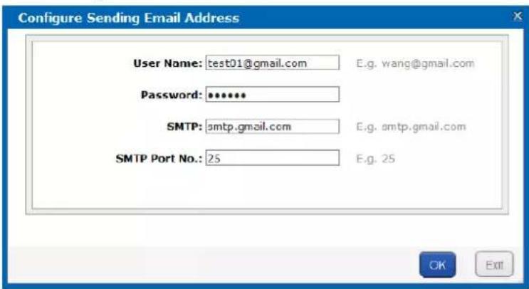
Figure 8.11 Configure Sending Email
8.2.2.2 Receiving Email
Steps:
- Click Add Email User.
- Enter Email and UserName.
- Choose EventLevel as Alarm Event or SeriousEvent.
- Click OK and click OK in confirmation dialog box to add the user. The added e-mail account is listed in List of email alarm users.
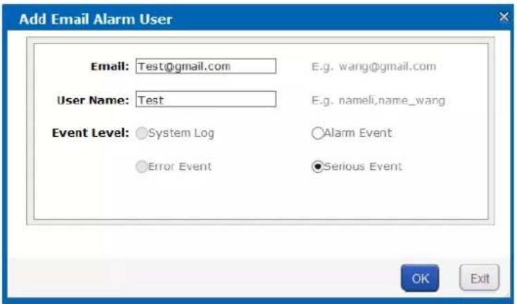
Figure 8. 12 Add Email Alarm User
8.2.3 Testing Email
Purpose:
After sending and receiving e-mail are configured, you can test the communication between them.
Steps:
-
Check the checkbox of sending e-mail you want to test.
-
Click 📋 Test button and click OK in confirmation dialog box to start test. The test result is listed in a message dialog box.
8.2.4 Adding SNMPManager
Purpose:
SNMP manager can notify the SNMP-Trap software installed in your computer about the storage system alarm. When alarm occurs, alarm message pops up in SNMP-Trap software.
Beforeyou start:
-
Install the SNMP-Trap software in your computer.
-
To receive alarm message in client, turn on Administration & Monitoring Tools in client.
Steps:
- Click.
Add SNMP manager
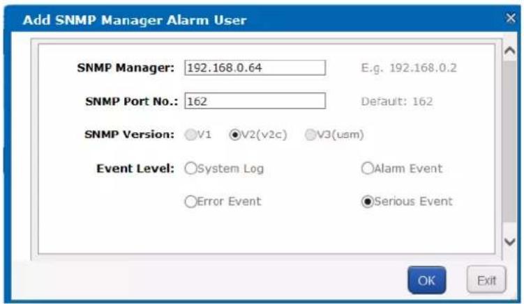
Figure 8. 13 Add SNMP Manager
- Enter SNMPManager and SNMPPort No. in the text field.
- SNMPVersionis V2(V2C) by default and is not editable.
- Choose Event Level as SystemLog, Alarm Event, Error Event, or SeriousEvent.
- Click OK and click OK in conformation dialog box. The added SNMP manager is listed in SNMP manager list.
8.2.5 Testing SMTPManager
Purpose:
You can test the network communication of SMTP manager.
Steps:
- Check the checkbox of SMTP manger to test.
- Click 📋 Test button and click OK to start test. Then test result pops up.
8.3 Time
Purpose:
System time is adjustable.
Steps:
Click Systemin navigation bar and choose Time.
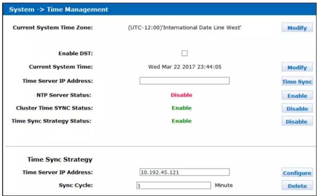
Figure 8. 14 Time Management
8.3.1 Adjusting SystemTime
8.3.1.1 Manual Adjust
Steps:
Do one or more of the following:
- Adjust Time Zone
- Click Modify of Current SystemTime Zone.
- Select time zone in the dropdown list.
- Click OK and click OK in confirmation dialog box.
- Adjust Date and Time
- Click Modify of Current SystemTime.
- Select date and time in text field.
- Click OK and click OK in confirmation dialog box.
8.3.1.2 Auto Adjust
Purpose:
The storage system automatically adjusts system time according to time server.
Beforeyou start:
Turn off the NTP server in client software.
Steps:
- Enter a correct Time ServerIP Addressin text field.
- Click Enableof NTPServerStatus to start auto time adjust.

Figure 8. 15 Adjust Time Automatically
8.3.2 SynchronizingTime
Purpose:
You can configure time synchronization strategy.
Beforeyou start:
● Turn off the NTP server in client software.
- Log in the storage system via resource IP address.
Steps:
- Click Enableof Time SyncStrategyStatus(Synchronization Strategy Status).
- Enter Time ServerIPAddressin text field
- Enter SyncCycle(Synchronization Cycle) in text field.
- Click Configureto start time synchronization.
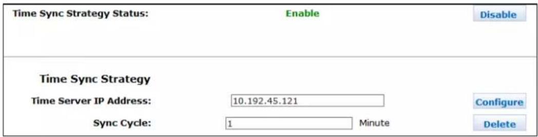
Figure 8. 16 Synchronize Time
Chapter 9 Log
Purpose:
Table 9.1 Module Description
| Module Description | |
| Log Download | You can download logs by downloading mode. |
| Operation log | It records the content and time of each operation. Search, download, and clear logs are supported. |
| Performance log | The storage system records the performance logs at every ten minutes. Performance log includes messages of CPU usage, memory footprint, network traffic, and array read and writing speed. |
| Update log | It records the details information of every system update. |
Keywords:
Log Download, Operation log, Performance log, Update log
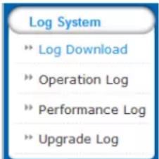
Figure 9.2 System
9.1 Operation Log
Purpose:
Operation log records the content and time of each operation. Search, download, and clear logs are supported. Steps:
Click Login navigation bar and choose Operation Log to enter Operation Log interface. Do one or more of the following:
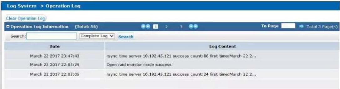
Figure 9.3 Operation Log
- View Logs

Figure 9.4 Paging
Click 📋/ button to turn to previous/next page. Click 📋/ button to turn to the first/last page. Or enter page number and click → to go to the designated page.
- Search Logs

Figure 9.5 Search Log
1) To search by time, enter date and time you want to search in Searchtext field. To search by log type, select log type in dropdown list.

Input correct data format, like March 23 2016 16:47:07.
2) Choose log type as All, Information, Warning, Error, or Seriousin dropdown list.
3) Click Search.Logsmeet the search conditions would be listed in operation window.
- Clear All Logs
Click ClearOperationLogand click OKin popup dialog to confirm.
9.2 Performance Log
Purpose:
The storage system records the performance logs at every ten minutes. Performance log includes messages of CPU usage, memory footprint, network traffic, and array read and writing speed.
Steps:
- Click Login navigation bar and choose Operation Log to enter Operation Log interface.
- For detailed steps of viewing and search performance logs, refer to section9.1 OperationLog.
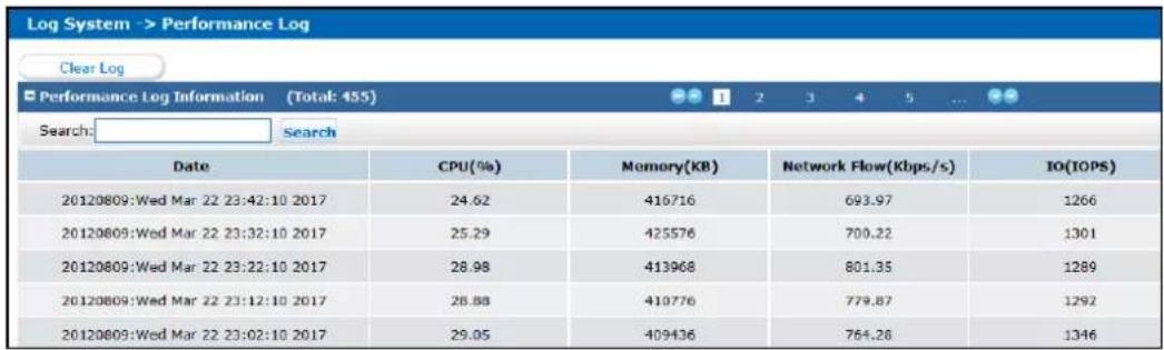
Figure 9.6 Performance Log
9.3 Upgrade Log
Purpose:
Update log records the details information of every system update.
Steps:
- Click Login navigation bar and choose UpgradeLog.
- To view logs and search logs, refer to section9.1OperationLogfor detailed steps.
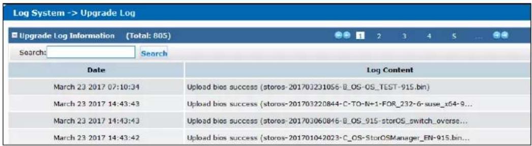
Figure 9.7 Update Log
0100001070327

See Far, Go Further
- Storage System UserManual
- Legal Information
- About this Document
- About this Product
- Acknowledgment of Intellectual Property Rights
- LEGAL DISCLAIMER
- RegulatoryInformation
- FCCInformation
- FCC Conditions
- EU Conformity Statement
- Industry Canada ICES-003 Compliance
- SafetyInstruction
- Warnings
- Table of Contents
- Chapter 1 Overview
- Purpose:
- Chapter 2 Getting Started
- HDDInstallation
- Accessingby Web Browser
- Steps:
- Login
- Chapter 3 Maintenance
- System
- Performance
- General
- Viewing Version Information
- Default Settings
- Managing Maintenance Log
- Modifying Password
- SNMPConfiguration
- Modifying Host Name
- Viewing ServiceStatus
- SystemUpgrade
- Graphical Display
- Front View
- Pie Chart
- Environmental
- Chapter 4 Storage Management
- Keywords:
- Managing Local HDD
- Viewing HDDStatus
- One HDD
- All HDDs
- Rescanning HDD
- Step:
- Positioning HDD
- HDDInitialization
- HDDDetection
- Array
- Creating Array
- Select the Available HDDsto create RAID.
- Click OK to create array. The successfully created array lists in Array information list. Once created, the array starts initializing.
- Array Exception
- Rebuilding Array
- Rebuilding with Hot Spare
- Rebuilding with Available HDD
- Detecting Array
- Repairing Array
- Renaming Array
- Modify I/O Priority
- Pause Initialization/Rebuilding/Detection/Repair
- Deleting Array
- Adding Hot Spare
- Deleting Hot Spare
- Storage Pool
- Adding Storage Pool
- Deleting StoragePool
- Positioning StoragePool
- LogicalVolume
- Creating LogicalVolume
- Deleting LogicalVolume
- Renaming Logical Volume
- Enlarging Logical Volume
- Configuration
- Synchronization Speed and Type
- Flickering Time
- Chapter 5 SAN
- iSCSI
- Adding CHAPUser
- Modifying CHAPUser
- Enabling iSCSI
- Disabling iSCSI
- Modifying iSCSIPort
- FC(Optional)
- Beforeyou start:
- Enabling FC
- Disabling FC
- Chapter 6 HYBRIDSAN
- One-KeyConfiguration
- HYBRIDSAN Configuration
- Starting HYBRIDSAN
- Resetting HYBRIDSAN
- RecordVolume
- Creating RecordVolume
- Clearing, Modifying, and Deleting RecordVolume
- Steps
- Extending
- Backup and Restoring
- Viewing Private Volume Information
- Restoring
- Backup
- Recovering Video Data
- N+1 Management
- Adding Backup HYBRIDSAN
- Deleting Backup HYBRIDSAN
- Adding Master HYBRIDSAN
- Before you start:
- Chapter 7 HYBRIDSAN Sub-System
- Accessby Web Browser
- Information
- Encoding Device
- Adding Encoding Device
- Modifying and Deleting
- Exporting and Importing EncodingDevice
- Previewing and Recording
- Strategy and Alarm
- Record Plan
- Simple RecordPlan
- Advanced Record Plan
- Exporting and Importing Advanced RecordPlan
- Upload Strategy
- BasicSettings
- Adding Uploading Tasks
- Adding Upload Plan
- Alarm
- Playing and Downloading
- SearchingVideo
- LockingVideos
- Playing Videos
- Whole Video Playback
- Downloading Videos
- One-KeyDownloading
- Block Downloading
- BatchDowloading
- User
- SystemConfiguration
- SystemAlarm
- HYBRIDSAN Version
- LogManagement
- Searching Log
- Exporting Log
- Clearing Log
- Chapter 8 System
- Network
- Modifying DataNetwork Interface
- Binding Network Interfaces
- Creating Bond
- Deleting Bond
- Modifying Bonding Mode
- Adding Route
- MACand IP Bonding
- Advanced Parameters
- DNSServer
- Binding Mode
- Bond Mode Description
- - Definition:
- - Advantage:
- - Disadvantage:
- Network Work Speed
- Alarm
- Alarm Type
- Adding Email
- Sending Email
- Click button.
- Configure SMTP
- Receiving Email
- Testing Email
- Adding SNMPManager
- Testing SMTPManager
- Time
- Adjusting SystemTime
- Manual Adjust
- Auto Adjust
- SynchronizingTime
- Chapter 9 Log
- Operation Log
- Performance Log
- Upgrade Log
Brand : Hikvision
Model : DS-A82024D
Category : Server