STR Preamplifier - Hi-Fi System Anthem - Free user manual and instructions
Find the device manual for free STR Preamplifier Anthem in PDF.


| Product Type | Preamplifier |
| Brand | Anthem |
| Model | STR Preamplifier |
| Dimensions (W x H x D) | 17.0 in x 4.5 in x 12.5 in (43.2 cm x 11.4 cm x 31.8 cm) |
| Weight | 20 lbs (9.1 kg) |
| Power Consumption | 50 W (standby <0.5 W) |
| Inputs | 5x analog RCA, 1x XLR balanced, 3x optical, 3x coaxial, 1x USB-B, 1x HDMI (ARC), phono MM/MC |
| Outputs | 1x XLR balanced, 1x RCA, 1x subwoofer, 1x headphone (6.3 mm) |
| Built-in DAC | 32-bit/768 kHz PCM, DSD256, AKM AK4490EQ |
| Phono Stage | Adjustable gain and loading for MM and MC cartridges |
| Streaming | Optional DTS Play-Fi module for Wi-Fi streaming |
| Room Correction | Anthem ARC Genesis (included) via USB and microphone |
| Remote Control | IR remote included; RS-232 and 12V trigger for automation |
| Frequency Response | 20 Hz - 20 kHz (+/-0.1 dB) |
| Signal-to-Noise Ratio | >110 dB (analog), >120 dB (digital) |
| Total Harmonic Distortion | <0.001% (analog), <0.0005% (digital) |
| Maintenance | Clean with a soft, dry cloth. Do not use liquids or solvents. |
| Safety | Disconnect power before cleaning. No user-serviceable parts inside. |
| Spare Parts & Repairability | Contact an authorized Anthem service center for repairs and genuine parts. |
Frequently Asked Questions - STR Preamplifier Anthem
User questions about STR Preamplifier Anthem
0 question about this device. Answer the ones you know or ask your own.
Ask a new question about this device
Download the instructions for your Hi-Fi System in PDF format for free! Find your manual STR Preamplifier - Anthem and take your electronic device back in hand. On this page are published all the documents necessary for the use of your device. STR Preamplifier by Anthem.
USER MANUAL STR Preamplifier Anthem
ANTHEM®
STR INTEGRATED AMPLIFIER
Operating Manual
CAUTION
RISK OF ELECTRIC SHOCK DO NOT OPEN

CAUTION: TO REDUCE THE RISK OF ELECTRIC SHOCK, DO NOT REMOVE COVER (OR BACK). NO USER-SERVICEABLE PARTS INSIDE. REFER SERVICING TO QUALIFIED SERVICE PERSONNEL
THE LIGHTNING FLASH WITH ARROWHEAD SYMBOL WITHIN AN EQUILATERAL TRIANGLE IS INTENDED TO ALERT THE USER TO THE PRESENCE OF UNINSULATED "DANGEROUS VOLTAGE" WITHIN THE PRODUCT'S ENCLOSURE THAT MAY BE OF SUFFICIENT MAGNITUDE TO CONSTITUTE A RISK OF ELECTRIC SHOCK TO PERSONS.

THE EXCLAMATION POINT WITHIN AN EQUILATERAL TRIANGLE IS INTENDED TO ALERT THE USER TO THE PRESENCE OF IMPORTANT OPERATING AND MAINTENANCE (SERVICING) INSTRUCTIONS IN THE LITERATURE ACCOMPANYING THE APPLIANCE.
WARNING: TO REDUCE THE RISK OF FIRE OR ELECTRIC SHOCK, DO NOT EXPOSE THIS APPARATUS TO RAIN OR MOISTURE, AND OBJECTS FILLED WITH LIQUIDS, SUCH AS VASES, SHOULD NOT BE PLACED ON THIS APPARATUS.
CAUTION: TO PREVENT ELECTRIC SHOCK, MATCH WIDE BLADE OF PLUG TO WIDE SLOT, FULLY INSERT.
CAUTION: FOR CONTINUED PROTECTION AGAINST RISK OF FIRE, REPLACE THE FUSE ONLY WITH THE SAME AMPERAGE AND VOLTAGE TYPE. REFER REPLACEMENT TO QUALIFIED SERVICE PERSONNEL.
WARNING: UNIT MAY BECOME HOT. ALWAYS PROVIDE ADEQUATE VENTILATION TO ALLOW FOR COOLING. DO NOT PLACE NEAR A HEAT SOURCE, OR IN SPACES THAT CAN RESTRICT VENTILATION.
IMPORTANT SAFETY INSTRUCTIONS
- Read these instructions.
- Keep these instructions.
- Heed all warnings.
- Follow all instructions.
- Do not use this apparatus near water.
- Clean only with a dry cloth.
- Do not block any of the ventilation openings. Install in accordance with the manufacturer's instructions.
- Do not install near any heat sources such as radiators, heat registers, stoves or other apparatus (including amplifiers) that produce heat.
-
Do not defeat the safety purpose of the polarized or grounding-type plug. A polarized plug has two blades with one wider than the other. A grounding-type plug has two blades and a third grounding prong. The wide blade or the third prong is provided for your safety. When the provided plug does not fit into your outlet, consult an electrician for replacement of the obsolete outlet.
-
Protect the power cord from being walked on or pinched, particularly at plugs, convenience receptacles and the point where they exit from the apparatus.
- Only use the attachments/accessories specified by the manufacturer.
- Use only with a cart, stand, tripod, bracket or table specified by the manufacturer, or sold with the apparatus. When a cart is used, use caution when moving the cart/ apparatus combination to avoid injury from tip-over.
- Unplug this apparatus during lightning storms or when unused for long periods of time.
- Refer all servicing to qualified service personnel. Servicing is required when the apparatus has been damaged in any way, such as power supply cord or plug is damaged, liquid has been spilled or objects have fallen into the apparatus, the apparatus has been exposed to rain or moisture, does not operate normally, or has been dropped.
WARNING: To reduce the risk of fire or electric shock, do not expose this apparatus to rain or moisture. Avoid installing this unit where foreign objects may fall onto this unit and/or this unit may be exposed to liquid dripping or splashing. On the top of this unit, do not place:
- Burning objects (i.e. candles), as they may cause fire, damage to this unit, and/or personal injury.
- Containers with liquid in them, as they may fall and liquid may cause electrical shock to the user and/or damage to this unit.
Apparatus shall not be exposed to dripping or splashing and no objects filled with liquids, such as vases, shall be placed on the apparatus.
Do not install this equipment in a confined space such as a case or similar. Install it away from direct sunlight, heat sources, vibration, dust, moisture, and/or cold.
Do not cover this unit with a newspaper, tablecloth, curtain, etc. in order not to obstruct heat radiation. If the temperature inside this unit rises, it may cause fire, damage to this unit, and/or personal injury.
Install this unit near the AC outlet and where the AC power plug can be reached easily.
This unit is not disconnected from the AC power source when it is turned off. This state is called the standby mode. In this state, this unit is designed to consume a very small quantity of power.
NOTE: This product is not an auto voltage Amplifier. Connect only to the prescribed AC outlet, i.e., 120V 60Hz or 240V 50/60Hz.
CAUTION: Top surface can become hot.
CAUTION: These servicing instructions are for use by qualified service personnel only. To reduce the risk of electric shock, do not perform any servicing other than that contained in the operating instructions, unless you are qualified to do so.
CAUTION: Changes or modifications to this equipment not expressly approved by Paradigm Electronics for compliance could void the user's authority to operate this equipment.
FCC WARNING: Changes or modifications not expressly approved by the party responsible for compliance could void the user's authority to operate the equipment.
This equipment has been tested and found to comply with the limits for a class B digital device, pursuant to part 15 of the FCC Rules. These limits are designed to provide reasonable protection against harmful interference in a residential installation. This equipment generates, uses and can radiate radio frequency energy and, if not installed and used in accordance with the instructions, may cause harmful interference to radio communications. However, there is no guarantee that interference will not occur in a particular installation. If this equipment does cause harmful interference to radio or television reception, which can be determined by turning the equipment off and on, the user is encouraged to try to correct the interference by one or more of the following measures:
- Reorient or relocate the receiving antenna.
- Increase the separation between the equipment and amplifier.
- Connect the equipment into an outlet on a circuit different from that to which the amplifier is connected.
- Consult the dealer or an experienced radio / TV technician for help.
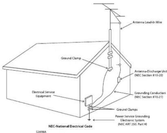
IMPORTANT INFORMATION FOR UK CUSTOMERS: DO NOT cut off the mains plug from this equipment. If the plug fitted is not suitable for the power points in your home or the cable is too short to reach a power point, then obtain an appropriate safety approved extension lead or consult your dealer. If, nonetheless, the mains plug is cut off, REMOVE THE FUSE and dispose of the PLUG immediately, to avoid possible shock hazard by inadvertent connection to the mains supply. If this product is not provided with a mains plug, or one has to be fitted, then follow the instructions given below:
IMPORTANT: DO NOT make any connection to the larger terminal which is marked with the letter "E" or by the safety earth symbol or colored GREEN or GREEN AND YELLOW.
The wires in the mains lead on this product are colored in accordance with the following code:
BLUE - NEUTRAL
BROWN - LIVE
As these colors may not correspond with the colored markings identifying the terminals in your plug, proceed as follows:
The BLUE wire must be connected to the terminal marked with the letter "N" or colored BLACK.
The BROWN wire must be connected to the terminal marked with the letter "L" or colored RED.
When replacing the fuse, only a correctly rated and approved type should be used, and be sure to re-fit the fuse cover. If in doubt consult a competent electrician.
NOTES ON ENVIRONMENTAL PROTECTION
At the end of its useful life, this product must not be disposed of with regular household waste but must be returned to a collection point for the recycling of electrical and electronic equipment. The symbol on the product, user's manual and packaging, point this out. The materials can be reused in accordance with their markings. Through re-use, recycling of raw materials or other forms of recycling of old products, you are making an important contribution to the protection of our environment. Your local administrative office can advise you of the responsible waste disposal point.
RECYCLING AND REUSE GUIDELINES (Europe)
In accordance with the European Union WEEE (Waste Electrical and Electronic Equipment) directive effective August 13, 2005, we would like to notify you that this product may contain regulated materials which, upon disposal, require special reuse and recycling processing. For this reason Paradigm Electronics Inc. (the manufacturer of Paradigm speakers and Anthem electronic products) has arranged with its distributors in European Union member nations to collect and recycle this product at no cost to you. To find your local distributor please contact the dealer from whom you purchased this product or go to our website at www.paradigm.com.
Please note that only the product falls under the WEEE directive. When disposing of packaging and other shipping material we encourage you to recycle through the normal channels.
INFORMATION ABOUT COLLECTION AND DISPOSAL OF WASTE BATTERIES (DIRECTIVE 2006/66/EC OF THE EUROPEAN PARLIAMENT AND THE COUNCIL OF EUROPEAN UNION) (for European customers only)
Batteries bearing any of these symbols indicate that they should be treated as "separate collection" and not as municipal waste. It is encouraged that necessary measures are implemented to maximize the separate collection of waste batteries and to minimize the disposal of batteries as mixed municipal waste. End-users are exhorted not to dispose waste batteries as unsorted municipal waste. In order to achieve a high level of recycling waste batteries, discard waste batteries separately and properly through an accessible collection point in your vicinity. For more information about collection and recycling of waste batteries, please contact your local municipality, your waste disposal service or the point of sale where you purchased the items.
By ensuring compliance and conformance to proper disposal of waste batteries, potential hazardous effects on human health is prevented and the negative impact of batteries and waste batteries on the environment is minimized, thus contributing to the protection, preservation and quality improvement of the environment.








CdHgPb
Anthem and any related party assume no liability for the user's failure to comply with any requirements.
Anthem, AnthemLogic, ARC, Sonic Frontiers, and Paradigm are trademarks or registered trademarks of Paradigm Electronics Inc. © Paradigm Electronics Inc. All rights reserved. The information contained herein may not be reproduced in whole or in part without our express written permission. We reserve the right to change specifications or features without notice as design improvements are incorporated.
All other trademarks are the property of their respective owners.
INTRODUCTION
1.1 Before Making Connections ..... 1
1.2 In-Use Notices ..... 1
1.3 Front Panel. 2
1.4 Rear Panel 3
1.5 Remote Control 4
1.6 Firmware Updates ..... 5
CONNECTIONS AND OPERATION
2.1 Speaker Connections ..... 7
2.2 Speaker Connections ..... 7
2.3 Analog Connections ..... 7
2.4 Local Area Network ..... 7
2.5 12 Volt Trigger ..... 7
2.6 Infra Red 7
2.7 Power ..... 7
SETUP
3.1 Speaker setup 9
3.2 Bass Management 10
3.3 Listener Position 11
3.4 Level Calibration ..... 12
3.5 Input Setup 13
3.6 Analog Input Levels 17
3.7 Preferences / Line Output 17
3.8 Network / Remote Control ..... 18
3.9 General Configuration 19
3.10 Save/load Settings 19
3.11 System Information 20
3.12 USB Audio 21
ANTHEM ROOM CORRECTION (ARC™)
4.1 Before Starting 24
4.2 ARC Software Installation 24
4.3 Microphone Stand Assembly ..... 25
4.4 microphone Positioning. 25
4.5 Measurement 26
4.6 Manual Mode and Targets 27
4.7 Advanced Subwoofer Targets ..... 30
4.8 Printing a Report. 30
OPERATION
5.1 Power On/Off and Volume ..... 31
5.2 Input Selection 31
5.3 Levels 32
5.4 Listening Modes ..... 32
5.5 Info Display 32
SPECIFICATIONS 33
LIMITED WARRANTY 36
NOTES 37
Thank you for purchasing the Anthem STR Integrated Amplifier
All Anthem products are engineered to recreate the passion of a live musical performance and emotional involvement experienced in the best movie theaters by utilizing the highest level of circuit design, superior parts and manufacturing techniques, innovative features, and intuitive ergonomics. We are confident that their inclusion in your system will significantly enhance your enjoyment of recordings for years to come.
1.1 BEFORE MAKING CONNECTIONS
Check that you have received all items listed below and report discrepancies to your dealer as soon as possible. In case the unit needs to be transported in the future, keep the packing materials.
Retain the invoice that you received from your authorized Anthem dealer at time of purchase – without it, service will not be provided under warranty.
Packing List:
- Integrated Amplifier
- Operating manual
- Remote control
- Two AAA batteries (included with 120V Models ONLY)
• USB type B cable for the USB audio input
• USB mini B cable for software updates and ARC (PC version)
• Dual-jack microphone
• 3.5mm microphone cable for ARC (mobile app version) - IEC power cord (US / UK / EU / CN types are supplied by the factory, other types are normally provided by the local distributor)
Additional items in Anthem Room Correction (ARC™) kit:
- USB Microphone
- Microphone clip
• Telescopic stand with boom
• USB mini B cable for the microphone
• CAT5 cable for connection to a router or network
1.2 IN-USE NOTICES
- Disconnect the power cord before connecting or disconnecting any components.
• If the amplifier was transported or stored in the cold, let it reach room temperature before use. - Do not remove the top cover.
- Do not modify the product.
- Due to continuing advances, operational characteristics may change. If this manual contains discrepancies please check www.anthemAV.com for the latest manual.
1.3 FRONT PANEL
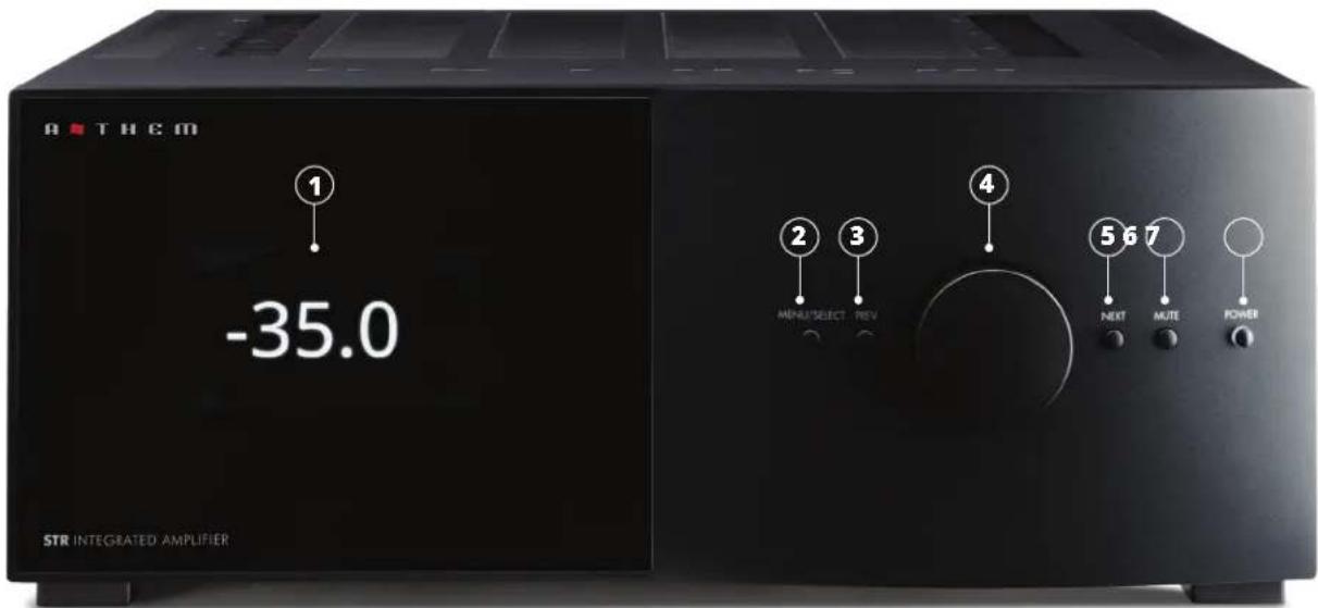
① Display
② Setup menu access and selection confirmation
③ Previous input or item
④ Volume control and menu navigation
⑤ Next input or item
⑥ Mute
⑦ Power
1.4 REAR PANEL
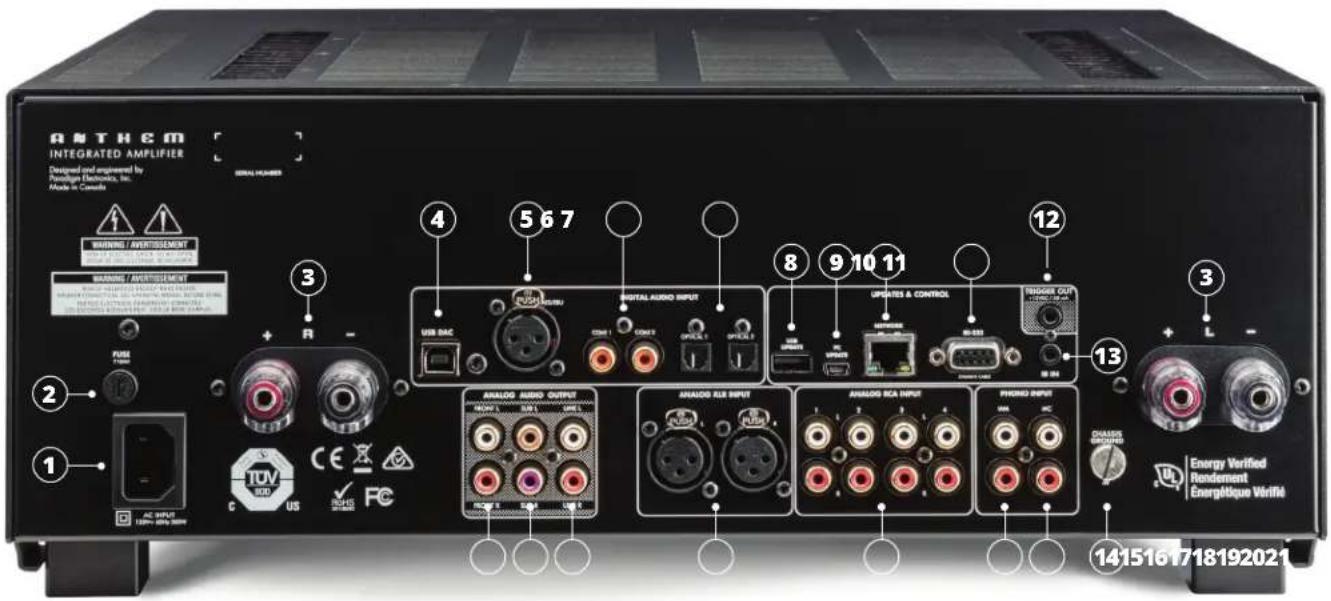
① Power cord inlet (IEC C18 type)
② Fuse
③ Speaker terminals
④ USB DAC input (Windows PCs need to have XMOS driver installed)
⑤ AES/EBU digital audio input
⑥ Coaxial digital audio inputs (2)
⑦ Optical digital audio inputs (2)
⑧ Factory Use Only
⑨ Software installation and ARC via PC
⑩ Ethernet connection for Anthem Room Correction, software installation and control
11 RS-232 (serial) connection for control
⑫ 12V DC / 50 mA trigger output
⑬ IR input
14 Phono ground terminal
⑮ Moving coil phono input
⑯ Moving magnet phono input
⑰ Analog RCA inputs (4)
18 Balanced XLR input
19 Line outputs (fixed-level, suitable for a headphone amp or recording device)
20 Subwoofer outputs (2, mono or stereo operation)
21 Left/Right preamplifier outputs (variable-level)
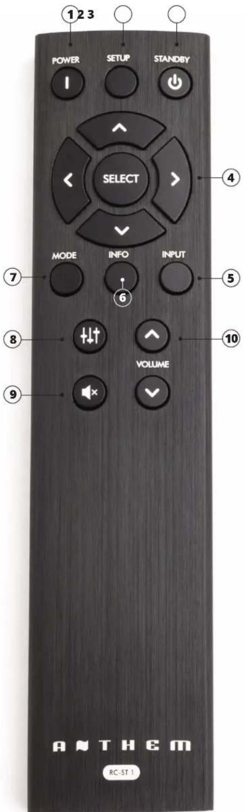
1.5 REMOTE CONTROL
① Power - On
② Setup menu
③ Power - Standby
④ Navigation
⑤ Input
⑥ Info (pertaining to input and output)
⑦ Listening Modes (mono/stereo)
⑧ Levels (sub, bass, treble, balance)
⑨ Mute
⑩ Volume
1.6 FIRMWARE UPDATES
The STR series supports software updates via network or mini-USB cable through the ARC (Anthem Room Correction) software. For more information on downloading this software please see section 4.1 of this manual.
STR firmware updates will help keep your products up to date as Anthem introduces new features and performance enhancements over the lifecycle of the product.
In order to initiate a firmware update open "ARC-2 Manual Mode" in the start menu.
To begin select "Tools->Firmware Update" from the taskbar.
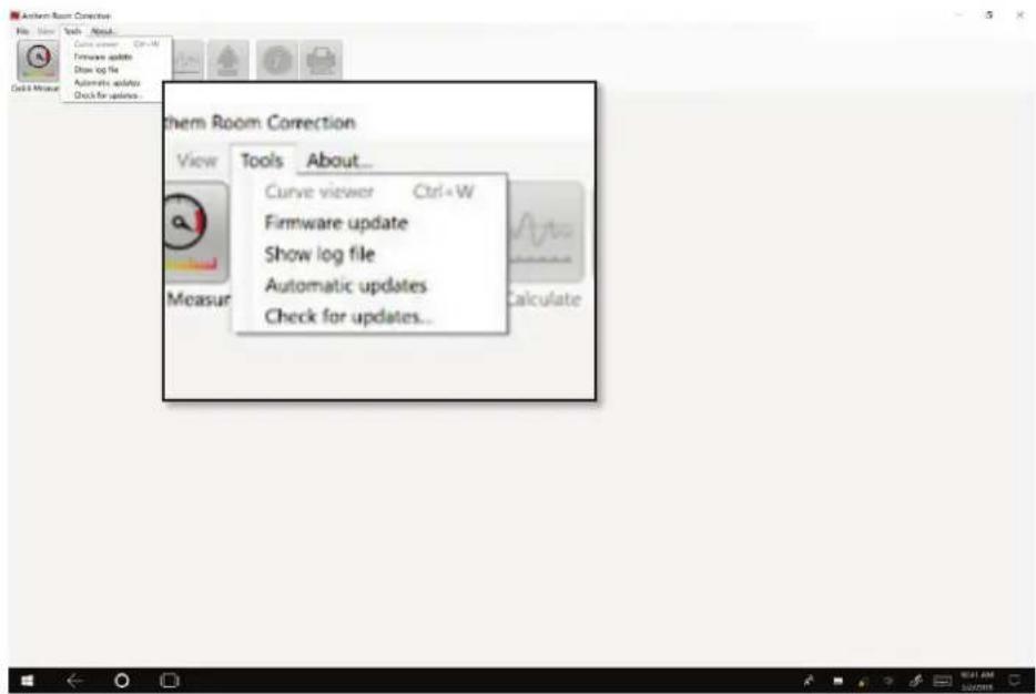
A dialog window will open asking you to select the device you wish to update.
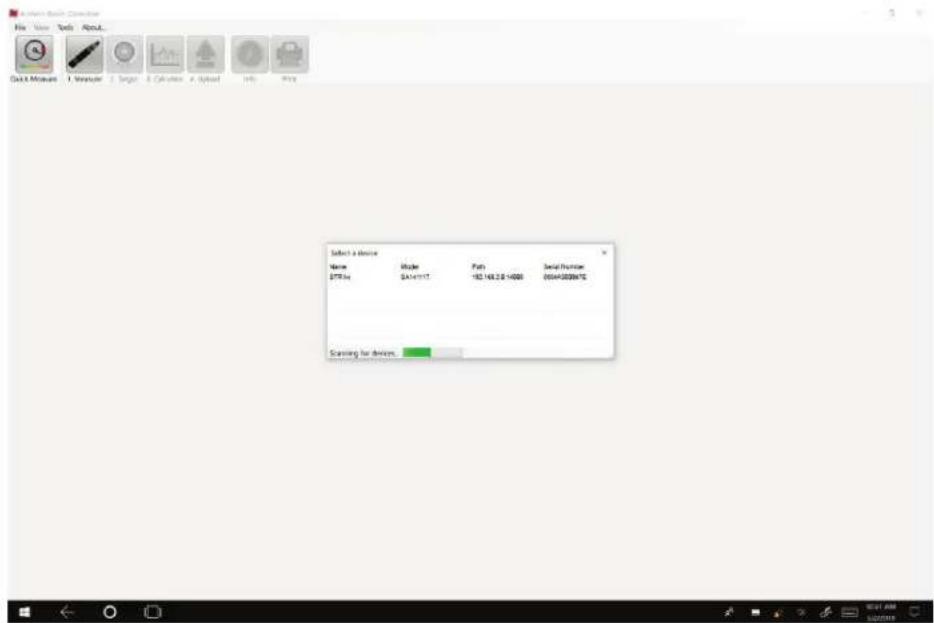
A dialog will open asking you whether you would like to manually select an update file.
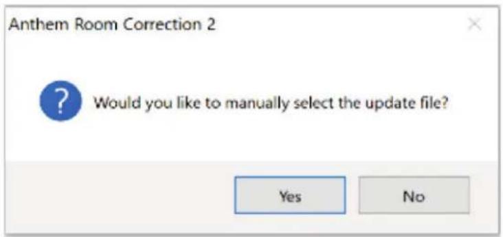
NO - Automatic Updates (Network Only)
For automatic network updates your STR will need to be connected to a router with an internet connection.
If you have an active internet connection you may select "No" and the STR will search online for the latest version of firmware. The update will begin and the unit will restart once complete.
YES - Manual Updates (Network or mini-USB)
For manual updates by network or mini-USB cable you will need to download the firmware file from anthemav.com.
Go to https://www.anthemav.com/support/latest-software.php and scroll to the STR product. Click download. The file will download as a .zip file and must be extracted. Once extracted you may finish the update process.
After selecting "Yes" you must browse to the folder you have saved the firmware (.upd extension) file and select it. The update will begin and the unit will restart once complete.
2.1 SPEAKER CONNECTIONS

Depending on the level of the input signal, the voltage at the outputs can be high enough to cause electric shock – be sure that power is turned off when connecting or disconnecting anything. As well, be sure that the speakers are rated for use with this amplifier – an overdriven speaker can pose a fire hazard.
Connect the red (+) connection on the speaker to the red (+) binding post on the amplifier, and the black (−) connection on the speaker to the black (−) binding post on the amplifier using cable that is insulated to handle the maximum output of the amplifier. Do not overtighten the binding posts as this may cause damage. The binding post pair accepts a connection from one speaker.
2.2 DIGITAL INPUT CONNECTIONS
Stereo digital audio sources can be connected using AES/EBU, coaxial or optical cable. The PCM stereo format up to 24-bit / 192 kHz is supported by all digital inputs. If using sources that have an option for selecting between PCM and Bitstream or Dolby Digital audio output, select PCM.
A personal computer can also be connected to the asynchronous USB DAC input. Stereo PCM up to 32-bit / 384 kHz, and DSD format up to 5.6 MHz are supported through this connection. Simply connect your computer and use media playing software on it to have music playing through your system. If using a Windows PC, the USB DAC driver must first be downloaded from our web site and installed. With Mac OS, just plug and play.
2.3 ANALOG CONNECTIONS
Balanced XLR connection offers the highest analog transmission quality, particularly over long cable lengths because it rejects noise and hum pickup. One such input is provided using the conventional pin-2 positive configuration. There are also four RCA line inputs.
For phono, there are two inputs. Be sure to use the correct one otherwise level will be affected and treble response may be altered. The MM input is suitable for turntables using moving-magnet and high-output moving-coil phono cartridges. The MC input uses input impedance and gain tailored to low-output moving-coil cartridges. As well, connect the ground wire from the turntable to the screw terminal next to the phono inputs to prevent excessive hum.
The subwoofer jacks are labelled "L" and "R" but if the system uses one subwoofer, it can be connected to any subwoofer output jack.
A network connection is required for configuring Anthem Room Correction or using IP control. Simply connect your router using CAT5 cable.
2.5 12 VOLT TRIGGER
If another system component has a trigger input it can be activated by the STR Integrated Amplifier. Connect the STR Integrated Amplifier's trigger output using a cable with 3.5mm mini plugs. The STR Integrated Amplifier provides flexible trigger options. Through the setup menu, you can specify the conditions for enabling triggers.
2.6 INFRA RED
An external IR receiver allows the remote control to be used from another location in your home – connect the STR Integrated Amplifier from an external IR hub to the IR IN jack. Most standard IR repeater kits can be used but to avoid problems test compatibility before installing permanently.
2.7 POWER
Connect the power cord to the STR Integrated Amplifier and the power source.
For optimum performance and enjoyment, your STR Integrated should be properly set up. This might seem like a lot of work at first because of the number of menu options, but most settings do not need to be changed from the defaults. The important ones relate to your input connections and speakers. If you're using a subwoofer or subwoofers, Anthem Room Correction will set crossovers and levels for a perfect blend with the main speakers. The rest of the settings mostly relate to your preferences.
HOW TO NAVIGATE IN THE SETUP MENU
Remote Control
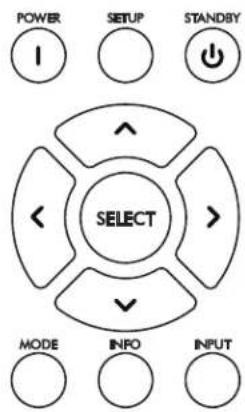
- Press Setup to enter or exit
- Press Up and Down arrows to move up and down on a list or to modify a selected item
- Press Right arrow or Select to select an item or to save a modification
- Press Left arrow to move up one menu level or to cancel a modification
TIP - modifying items which have many options, especially the alphanumeric characters and symbols when renaming an input, is faster using the front panel volume control.
Front Panel
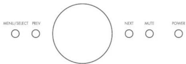
flowchart
graph LR
    A["MENU/SELECT"] --> B["○"]
    C["PREV"] --> D["○"]
    E["NEXT"] --> F["○"]
    G["MUTE"] --> H["○"]
    I["POWER"] --> J["○"]
- Press Menu/Select two times to enter and once to exit
- Use the Volume control to move up and down on a list or to modify a selected item
- Press Next to select an item or to save a modification
- Press Prev to move up one menu level or to cancel a modification
The help line at the bottom of the display will also guide you through various menu levels.
The display shows up to four menu selections at once, though in this section of the manual all menu items are shown together for simplicity. The top menu contains these items:
Setup Menu
Speaker Setup
Bass Management
Listener Position
Level Calibration
Input Setup
Analog Input Levels
Preferences
Network/Remote
General Configuration
Save/Load Settings
System Info
3.1 SPEAKER SETUP
Normally only one speaker configuration is needed but more are provided for instant recall of stored subwoofer or Anthem Room Correction settings.
If you will be using the personal computer version of ARC, you can skip this menu since it will be set while the program is running.
Speaker Setup
Config 1
Config 2
Config 3
Config 4
Each configuration contains this submenu:
Speaker Edit
Name Config 1
Subwoofers
Off
PROFILE NAME
Using the navigation keys and volume knob each profile can be renamed, up to 10 characters long. Note that the profile name is best set in Anthem Room Correction (Targets panel) because during file upload the name in the menu is overwritten by the one in ARC.
SUBWOOFERS
The STR Integrated Amplifier allows one or more subwoofers to be connected.
Although subwoofers are often thought of as something for home theater systems, their use is recommended for music as well. A subwoofer normally plays bass that is louder, deeper, and less distorted than that of a full-range speaker, and it can be positioned anywhere in the room to help cure resonances that otherwise make the bass sound bloated and lacking definition. Anthem Room Correction quickly and easily creates precise calibration and seamless integration with the main speakers, eliminating unnatural sounding transitions which often made subwoofers and main speakers sound disconnected from one another regardless of the amount of time spent on tweaking.
The setting options are:
- Off – select this if there is no subwoofer in the system or speaker profile.
- 1 Mono – a mono music signal gets sent to all subwoofer jacks. ARC will measure and correct all the subwoofers as a group. This is the generally recommended setting whether using one or more subs.
- 2 Mono – a mono music signal gets sent to all subwoofers but ARC will measure and correct them separately for the L and R output jacks. Select this if you intend to control the delay (distance) and level separately for each subwoofer channel.
- 2 Stereo – the bass from the music source's left channel will be sent to the L subwoofer output and the bass from the right channel will go to the R output. ARC will measure and correct the L and R subs individually. Select this if you have a subwoofer next to each main speaker and would like for them to use a stereo bass signal, especially if the crossover frequency will be set closer to upper bass where the sound becomes directional.
3.2 BASS MANAGEMENT
In this menu, information about your speakers is used to optimize bass performance.
First, set your subwoofer's frequency control to its highest frequency since the bass manager will determine how much upper bass is sent. If your subwoofer has a contour control, set it to flat if you will be using Anthem Room Correction. If it has a phase control, set it to 0 and if it has a polarity switch, set it to Normal as you'll be able to control phase and polarity from your listening chair and hear changes instantly.
The bass manager divides the audio range into two bands suitable for subwoofer/satellite speaker systems. The result is that the main speakers don't need to play bass as loudly or as deeply since it gets picked up by the subwoofer. Note that a crossover does not suddenly cut frequencies in a cliff-like profile, but rolls them off according to a slope. If set to 80 Hz, for example, frequencies lower than 80 Hz are still played by the main speaker while transitioning them to the subwoofer.
Highlighting Bass Management then pressing Select displays this menu:
Bass Management
Config 1
Config 2
Config 3
Config 4
Four configurations may be set up. Each contains the following:
Bass Management Edit
Crossover
Off
Sub L Polarity Normal
Sub R Polarity Normal
Sub L Phase 0
Sub R Phase 0
CROSSOVER FREQUENCY
The range is 25 to 160 Hz in 5 Hz steps, or Off which disables the crossover.
Setting the crossover to the lowest number on your speaker's specification page is unlikely to provide the best result. Instead, setting it to twice this frequency or thereabout, which is an octave higher, ensures that the speaker's woofer will still play to its low frequency limit but at levels that present less of a struggle for it.
If you will be using the personal computer version of ARC, you do not need to select the crossover frequency since it will be set while running the program.
SUBWOOFER POLARITY AND PHASE
Certain subwoofer positions can cause bass frequency cancellation. When the front speakers and subwoofer are out of phase or misaligned, they work against each other resulting in weak and dislocated sounding bass. This can be corrected by adjusting Phase and Polarity.
As a general guide, set Polarity to Normal if the subwoofer is near the front speakers and to Inverted if the subwoofer is near the back of the room. Compare Normal to Inverted and use the setting that provides louder bass. Continue fine-tuning the crossover region using the Phase control which provides adjustment from 0 to 180 degrees in 5 degree increments.
3.3 LISTENER POSITION
Through these settings, sound coming from all speakers is coordinated to reach the listening area at the same time. This way, proper imaging is achieved. The channel with the greatest distance setting will have no delay while channels with shorter distance settings will be delayed accordingly.
Distances may be set before or after running ARC (ARC does not set distances).
Listener Position
Config 1
Config 2
Config 3
Config 4
These settings are displayed for each configuration:
Listener Position Edit
| Units | Feet |
| Sub Left 12' 0" | |
| Sub Right 12' 0" | |
| Front Left 12' 0" | |
| Front Right 12' 0" |
For measurement units, select feet or metres and enter the distance between your primary listening area and each speaker. Range is 0 to 29' 6" in 2-inch increments or 0.00 to 9.00 m in 5 cm increments.
Level Calibration uses internally generated test noises to match speaker output levels at the listening position, if using an SPL meter for calibration.
If using Anthem Room Correction, you can skip this menu because levels will be calibrated during measurement.
Level Calibration
Config 1
Config 2
Config 3
Config 4
These settings are displayed for each configuration:
Level Calibration Edit
Test Noise Off
Noise Level 0.0dB
Sub Left 0.0dB
Sub Right 0.0dB
Front Left 0.0dB
Front Right 0.0dB
To play the test noise, set it to "On" then highlight a speaker.
A sound pressure level (SPL) meter with C-weighting is recommended if not using ARC, especially to set the subwoofer level because it is often set too high when calibrating by ear. Measure the sound pressure from the listening position while pointing the meter up. Hold it away from your body to prevent reflections. Adjust each channel's level so the meter has the same reading with all speakers.
The level adjustment range is -12.0 to 12.0 dB in 0.5 dB increments. You may need to adjust your subwoofer's input level dial as a rough adjustment.
3.5 INPUT SETUP
Inputs and listening mode presets are configured in this section. From the factory, all input jacks are configured and named accordingly but you may change this to anything from 1 to 30 input configurations.
| Input Setup |
| Coaxial 1 |
| Coaxial 2 |
| Optical 1 |
| Optical 2 |
| AES/EBU |
| USB |
| RCA 1 |
| RCA 2 |
| RCA 3 |
| RCA 4 |
| Phono MM |
| Phono MC |
| XLR 1 |
| XLR 2 |
| Add Input |
| Insert Input |
| Delete Input |
| Configure HT Bypass |
To add an input at the end of the list, highlight Add Input and press Next.
To insert an input in the middle of the list, highlight Insert Input and press Next. The display will guide you through the remaining steps.
To delete an input, highlight Delete Input and press Next. The display will guide you through the remaining steps.
HOME THEATRE BYPASS
Home Theatre Bypass is a feature that allows you to use the STR Integrated as a 2-channel amplifier in conjunction with your home theatre processor. Activating HT Bypass configures a single analog input to be used without digital processing, it will also disable the STR Integrated volume control and mute function when enabled.
When the Home Theatre Bypass input is selected only the Left and Right channels will be active, subwoofers connected only to the STR Integrated will not receive signal and will remain inactive.
Home Theatre Bypass is found by entering the setup menu and selecting the "Input Setup" option. Scroll to the bottom and there will be a menu item "Configure HT Bypass", select this option.
Home Theater Bypass requires the selection of a single analog source (RCA1, RCA2, RCA3, RCA4, or XLR1). The selected input will remain in the input selection list but will now have an additional HTB label.
HT Bypass can be activated regardless of the input through RS232 and IP via the special command "Z1INP32";
These settings are displayed for each configuration, though a phono input is shown here because it uses all menu items:
Input Edit
Name Phono MC
Input Jack Phono MC
Convert Analog 32/192
Speaker Profile Profile1
Front Right 12' 0"
ARC Yes
Mode Preset Stereo
Rumble Filter 35 Hz
Phono EQ RIAA
Bass Turnover
Bass Shelf
10k De-Emphasis
NAME
Each input can be renamed, up to 10 characters long. To begin editing, press Next. The volume knob is the fastest means of changing characters. Use the Next button to move to the next character, and when finished renaming, select the green checkmark. To cancel editing, press Prev to select the red X.
Example – Rename "Optical 1" to "Server":
- Highlight "Name" and press Next. The first character will have a box around it.
- Use the up/down buttons or volume knob to change "O" to "S".
- Use the Prev/Next buttons to move to each remaining character and complete the renaming.
- Move the box to the green checkmark to save the changes.
INPUT JACK
Select the connection to be used – Coaxial 1, Coaxial 2, Optical 1, Optical 2, AES/EBU, USB, RCA 1, RCA 2, RCA 3, RCA 4, Phono MM, Phono MC, XLR.
CONVERT ANALOG
By default, analog inputs are converted to 32-bit / 192 kHz using a high-quality A/D converter to allow Anthem Room Correction, bass management, distance calibration, bass/treble controls, listening modes, and rumble filter. If this setting is changed to No, signal processing is bypassed and only level adjustment remains.
SPEAKER PROFILE
Select the profile to use with this input.
ANTHEM ROOM CORRECTION (ARC™)
The ARC measurement process, described later, will turn this on. To disable room equalization afterward, change this to "No". If a measurement file isn't loaded, this menu item is grayed.
MODE PRESET
By default, the output is in stereo but one of the other settings may improve the sound of old records. The mode can be changed on the fly but in this menu you can assign a preset according to input configuration.
- Stereo – this is the default and does not alter the channel mix.
- Mono – this blends the left and right channels and can be useful when playing mono records with a stereo cartridge. Without this, stereo noise flanking mono music can be distracting.
- Both = Left – this sends the left input to both channels and can be useful when playing a mono record with a stereo cartridge when the left groove wall has less wear and sounds better than the right groove wall. This is also useful with sources that have only one output connector.
- Both = Right - like above but for the right channel.
- Last Used – select this to disable presets and make selections entirely on the fly.
RUMBLE FILTER
Use this with a turntable to reduce or eliminate low-frequency noise below the music spectrum. Rather than rolling off all content including the music, the filter acts only on vertical stylus motions that are inherently not part of the music signal. This is especially effective with warped records that cause excessive or non-musical woofer motion. Select a frequency from 10 to 60 Hz in 1 Hz increments. To disable the filter, select Off.
PHONO EQ
The Phono EQ, Bass Turnover, Bass Shelf, and 10k De-Emphasis controls allow the proper equalization of records that predate the RIAA equalization standard. If no records in your collection were manufactured before the 1960s, you can skip the rest of this section.
To make record grooves manageable, bass is reduced when records are manufactured, while the treble is emphasized. The main function of a phono preamp is to reverse this equalization upon playback, restoring the intended frequency response. The problem is that before the record industry settled on an equalization standard, resulting in the RIAA curve during the 1950s, the amount of reduction and emphasis varied requiring multi-curve phono preamps for proper playback. Today, such phono stages are rare. This means that if a phono stage that was designed for only one kind of record is used to play older mono records, there will be too much treble, midrange, or bass, or not enough of it.
These menu settings give you the ability to play all old records with their intended frequency response:
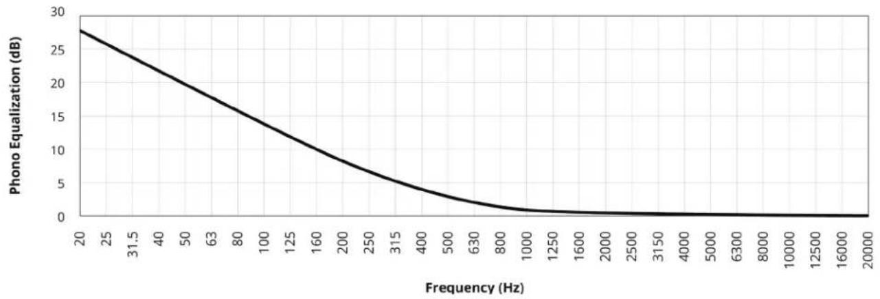
BASS TURNOVER – the frequency at which 3 dB boost occurs. In this example, it is 500 Hz:
line
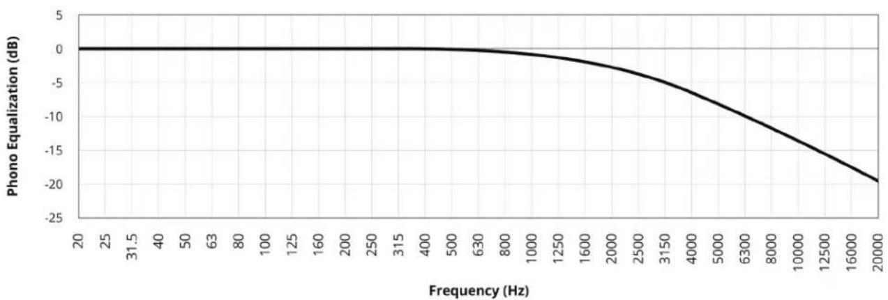
| Frequency (Hz) | Phono Equalization (dB) | | -------------- | ------------------------ | | 20 | 28 | | 31.5 | 24 | | 40 | 20 | | 50 | 16 | | 63 | 12 | | 80 | 8 | | 100 | 4 | | 125 | 2 | | 160 | 1 | | 200 | 0.5 | | 250 | 0.3 | | 315 | 0.2 | | 400 | 0.1 | | 500 | 0.05 | | 630 | 0.03 | | 800 | 0.02 | | 1000 | 0.01 | | 1250 | 0.005 | | 1600 | 0.003 | | 2000 | 0.002 | | 2500 | 0.001 | | 3150 | 0.0005 | | 4000 | 0.0003 | | 5000 | 0.0002 | | 6300 | 0.0001 | | 8000 | 0.0001 | | 10000 | 0.0001 | | 12500 | 0.0001 | | 16000 | 0.0001 | | 20000 | 0.0001 |10K DE-EMPHASIS – the attenuation at 10 kHz. In this example, it is -13.7 dB:
line
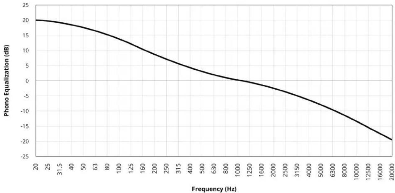
| Frequency (Hz) | Phono Equalization (dB) | | -------------- | ------------------------ | | 20 | 0 | | 31.5 | 0 | | 40 | 0 | | 50 | 0 | | 63 | 0 | | 80 | 0 | | 100 | 0 | | 125 | 0 | | 160 | 0 | | 200 | 0 | | 250 | 0 | | 315 | 0 | | 400 | -1 | | 500 | -2 | | 630 | -3 | | 800 | -4 | | 1000 | -5 | | 1250 | -6 | | 1600 | -7 | | 2000 | -8 | | 2500 | -9 | | 3150 | -10 | | 4000 | -11 | | 5000 | -12 | | 6300 | -13 | | 8000 | -14 | | 10000 | -15 | | 12500 | -16 | | 16000 | -17 | | 20000 | -18 |The following curve combines the two above and adds BASS SHELF or boost limit at 20 Hz, which is 20 dB in this example:
line
| Frequency (Hz) | Phono Equalization (dB) | | -------------- | ------------------------ | | 20 | 20 | | 31.5 | 19 | | 40 | 18 | | 50 | 17 | | 63 | 16 | | 80 | 15 | | 100 | 13 | | 125 | 11 | | 160 | 9 | | 200 | 7 | | 250 | 5 | | 315 | 3 | | 400 | 1 | | 500 | -1 | | 630 | -3 | | 800 | -5 | | 1000 | -7 | | 1250 | -9 | | 1600 | -11 | | 2000 | -13 | | 2500 | -15 | | 3150 | -17 | | 4000 | -19 | | 5000 | -21 | | 6300 | -23 | | 8000 | -25 | | 10000 | -27 | | 12500 | -29 | | 16000 | -31 | | 20000 | -33 |The graph above represents the RIAA playback curve. Older phono curves use other amounts of bass boost, bass shelf, and treble cut, often expressed in this format:
500R-13.7
where 500 is the bass turnover in Hz, -13.7 is the 10 kHz de-emphasis in dB, and R is the bass shelf according to: N (None), R (20dB), B (18dB), A (16dB), C (14dB), X (12dB).
When Convert Analog is set to 32/192, the following Phono EQ options become available:
500R-13.7 (RIAA)
400N-12.3 (AES)
350N-10.5 (CCIR)
500B-16 (NAB)
400N-12.7 (Capitol LP)
500C-16 (Columbia LP)
500C-10.5 (London LP)
User
Select according to the record that you are playing. For pre-RIAA long-playing records, check whether the jacket indicates "AES", "CCIR", "NAB", etc. You can also check one of several web sites which provide code lists according to record label and year. They can be found by searching the web for 500R-13.7 or playback equalization for 78 rpm shellacs and early 33-1/3 LPs – don't forget to use a properly sized 78 rpm stylus if playing 78 rpm records.
To create or fine-tune any curve, select User and enter Bass Turnover, Bass Shelf, and 10k De-Emphasis according to the code list, or adjust by ear – it's like using bass/treble controls except that these are specially made ones for phono.
BASS TURNOVER options are None, 150, 180, 200, 250, 280, 300, 350, 375, 400, 450, 500, 600, 629, 700, 750, 800, and 1000 Hz.
The 10K DE-EMPHASIS adjustment range is from -25.5 dB to None in 0.1 dB increments.
Although the purpose of these controls is to provide the correct response with old records, you might find similar uses, for example to brighten a muffled-sounding stereo LP, or to add weight to a thin-sounding one. This is fine as long as extreme settings that would result in overload or a distorted sound are avoided.
Each virtual input stores its own curve settings. This way, you can create multiple profiles for your turntable input, each using a different curve according to the records in your collection.
3.6 ANALOG INPUT LEVELS
Through this menu, unwanted changes in volume when switching to or from an analog source can be prevented. This is especially useful for some XLR sources that produce higher than typical output level, and for the phono inputs since cartridge output levels vary considerably between models.
Analog Input Levels
RCA 1 0.0dB
RCA 2 0.0dB
RCA 3 0.0dB
RCA 4 0.0dB
Phono MM 0.0dB
Phono MC 0.0dB
XLR 0.0dB
The adjustment range for raising or lowering the input level is -20 to 20 dB in 0.5 dB increments.
3.7 PREFERENCES / LINE OUTPUT
Here you can set preferences as listed.
Preferences
Display Brightness Medium
Display Wakeup High
Displayed Info Volume
Mute Level Muted
Maximum Volume 6.0dB
Power-On Volume -35.0dB
Power-On Input Last Used
Mute Line Out None
DISPLAY BRIGHTNESS
Set preferred front panel brightness between Max, High, Medium, Low or Off.
FRONT PANEL WAKE-UP
When a button is pressed the display can go to a brighter level for 5 seconds – select Max, High, Medium, or Low.
DISPLAYED INFO
By default, only the volume is displayed. Select "All" to add the input, input format, mode, and ARC status to the display.
MUTE LEVEL
When Mute is pressed, sound can be muted or lowered to background level. Select from Muted, -30 dB, -20 dB, or -10 dB.
MAXIMUM VOLUME
This setting allows you to limit the volume to avoid damaging equipment and/or hearing.
POWER-ON VOLUME
The volume will be at this level when the unit is turned on. To power-on at the last used volume, set the volume preset below -96.0 to make Last Used appear.
POWER-ON INPUT
The input will be the assigned one or Last Used when the unit is turned on.
MUTE LINE OUT
If using a recording device, select the input that the recorder's output is connected to. This prevents the recorder's output from being fed back to its input, which can result in a loud noise.
3.8 NETWORK / REMOTE CONTROL
Network / Remote
Status 192.168.000.001
Device Name STR Int
IP Configuration
RS-232 Configuration
Trigger Control
Rear IR Off
Front IR On
NETWORK STATUS
This displays the unit's IP address once connected to the local area network.
DEVICE NAME
This is the name that the unit broadcasts, and can be changed using up to 8 characters.
IP CONFIGURATION
Settings in this submenu should only be changed by a network administrator.
IP Configuration
Mode Auto (DHCP)
IP 192.168.000.001
Subnet Mask 255.255.255.000
MODE
Static IP settings take effect once this is changed to Manual.
When the unit's trigger output is connected to the trigger input of another component such as an amplifier, it can be turned on or off according to the trigger's setup (12 VDC, max 50 mA).
- Trigger Control – select Menu to configure triggers via the setup menu, or RS-232/IP to control the trigger output through serial or IP commands.
- Power - when set to Yes, the trigger activates when the unit's power is turned on. When set to No, the input list appears and the trigger can be configured to activate through any combination of input selection.
REAR AND FRONT IR
This allows you to disable each of the infra-red inputs, which can be useful when the unit is connected to an IR repeater and is receiving too many signals.
Note that the moment that you disable the front IR input, you will not be able to control the unit the traditional way from the remote control. Re-enable it using the front panel buttons. If your remote control appears to not be working and you have checked the batteries, check this menu next before contacting technical support.
3.9 GENERAL CONFIGURATION
This menu contains power saving and control options.
General Configuration
Auto Off 20 Minutes
Standby IP Off
AUTO OFF
When there is no input signal the unit will turn off after the selected time: 5, 10, or 20 minutes, 1, 2, or 6 hours, or Never.
STANDBY IP CONTROL
When disabled, the unit goes into a low-consumption standby mode and does not sense IP commands. To make it respond to a power-on command, enable this setting. This can also be used with RS-232 control to avoid sending a wake-up command.
3.10 SAVE/LOAD SETTINGS
Save / Load Settings
Save User Settings
Save Installer Settings
Load User Settings
Load Installer Settings
Reset On-The-Fly Settings
Load Defaults
SAVE/LOAD USER AND INSTALLER SETTINGS
After selecting Save User Settings and confirming, all menu settings will be stored. If you change settings later and want to recall the saved settings, select Load User Settings and confirm. The same applies to saving and recalling installer settings.
RESET ON-THE-FLY SETTINGS
After selecting and confirming, all non-menu settings such as level and bass/treble will be reset.
LOAD DEFAULTS
After selecting and confirming, all menu settings will be reset.
FACTORY RESET
Use this only as a last resort if the unit becomes inoperable. Disconnect the power cord and re-connect it while holding the front panel power button. Do not let go of the button until something appears on the display. The unit will revert to the software it was manufactured with and all settings will be reset.
3.11 SYSTEM INFORMATION
System Info
Update via USB
Firmware Version 0.1.5078
FW Date 01/27/17 14:38
ARC Name
ARC Date
MAC 00:04:A3:93:FA:62
FIRMWARE VERSION AND UPDATES
The operational characteristics of the STR Integrated Amplifier are controlled by software. For best performance and latest features, ensure that your unit is running the newest software. This gets installed through Anthem Room Correction which is fully explained in the next section. In this section only the STR software update is explained.
If your STR is connected to your network with internet access, you do not need to manually download the update from our web site. Alternatively, the update can be downloaded from our web site first and installed afterwards.
Without network connection:
- On www.anthemAV.com locate the software pertaining to your model. Proceed only if your version number is lower, indicating that it is older.
- You will be asked where to save a .zip file – save it to Desktop.
- When the .zip file download is complete, extract it to Desktop.
• See Read Me.txt for the change history. - Connect your computer to the STR rear panel USB jack labeled PC UPDATE using the supplied USB cable or similar one.
- Using ARC software, select Tools at the top of the window, then Firmware Update, and follow its instructions to manually update using the file on Desktop.
With network connection:
- Ensure that your STR is on the same network as your computer, and that the network has Internet access.
- Using ARC software, select Tools at the top of the window, then Firmware Update. When it asks whether you would like to update manually, select "No" and it will check our web site for updates.
Installation takes less than 10 minutes and the display will indicate progress. Do not interfere by pressing buttons or turning power off – the unit will turn on and off by itself a few times. At the end it will remain on with the normal volume info on the display.
ARC NAME
This is the name that you gave to your measurement file.
ARC UPLOAD TIME
This is the date and time that your ARC file was uploaded.
MAC ADDRESS
This is the unit's unique identifier for network communication.
3.12 USB AUDIO
Your computer can be used as a music source by connecting its USB port to the USB DAC input on the STR Integrated and running the media player on your computer that you normally use for playing music.
Mac does not require setup for this purpose - just plug and play (OS 10.6.4 and higher supports USB Audio Class 2.0).
For PC, a driver needs to be installed to add USB audio functionality:
- Download the XMOS driver from www.anthemav.com.
- Extract XMOS-Stereo-USB-Audio-Class2-Driver.exe to Desktop and double-click it.
- Run the installation. It will ask whether you'd like to connect the device later. If selecting No, first connect a USB port on your PC to the USB DAC input on the STR Integrated and turn it on.
Once driver installation is complete the installer may be deleted. Your PC, through its music playing software, will be ready to stream music to the STR Integrated.
DSD PLAYBACK
If you're planning to play DSD audio files, ensure that your computer's software supports the format.
Optional - For PC, a popular and free program is called Foobar. This can be set up for DSD as follows*:
- Install the Foobar2000 music player which is available from this web page:
http://www.foobar2000.org/download
-
Install the SACD (DSD) decoder:
-
Download foo_input_sacd-1.0.x.zip from: https://sourceforge.net/projects/sacddecoder/files/latest/download
- From the zip file, copy foo_input_sacd.fb2k-component to this directory:
(Computer, OS) C:\Program Files (x86)\foobar2000\components
- Run Foobar2000 and go to File / Preferences / Components.
- Select Install and browse to the foobar2000\components directory.
- Select foo_input_sacd.fb2k-component then click Open.
-
Select Apply to complete this installation.
-
Install the ASIO driver:
-
Download foo_out_asio.fb2k-component from: http://www.foobar2000.org/components/view/foo_out_asio
- Move foo_out_asio.fb2k-component to this directory:
(Computer, OS) C:\Program Files (x86)\foobar2000\components
- Run Foobar2000 and go to File / Preferences / Components.
- Select Install. Browse to the foobar2000\components directory if necessary.
- Select foo_out_asio.fb2k-component then click Open.
-
Select Apply to complete this installation.
-
Configuring Foobar for DSD:
-
Go to File / Preferences / Playback / Output.
- In the Device pull-down list, select the following then click Apply:
DSD : ASIO : XMOS USB AUDIO 2.0 ST 308F (or newer)
- Go to File / Preferences / Tools / SACD.
- Change Output Mode to DSD+PCM and click OK.
Upon completion of these steps, your PC is ready to stream music from DSD files.
If you have trouble with Foobar installation or use, please do not contact our tech support regarding it. A solution may be available using an online search.
* These steps regarding installation and use of third party software and its components are provided for informational purposes only.
For anyone reading this, the experience of walking into a room and being struck by the dramatic change in its sound after carpet and furnishings have been moved out is probably a familiar one. It may also bring to mind the varying sound character from one room to the next according to its size and structural qualities.
By the same token, even when the finest speakers are optimally positioned, the room impacts sound quality considerably. The walls, floor, ceiling, and windows add unwanted resonance and coloration making bass less impactful, voices less natural, and dialogue less intelligible. The effect on frequency response is typically ±6 dB in the midrange and ±10 dB at low frequencies. To compensate for this and to optimize the in-room response of your speakers, Anthem Room Correction measures the output of each one relative to the listening area then through a special series of calculations adjusts the output accordingly. Its target responses have a psychoacoustic basis from research results, not just theoretically ideal curves.
While removing resonances and modal peaks common to the measurement positions, ARC also distinguishes and preserves the positive effects imparted by the room by detecting how much the room's boundaries and pressurization reinforce low frequencies. This effect, known as room gain, appears as a bump in the target response. ARC does not remove it because if flattened, bass sounds thin. Our ear/brain mechanism expects to hear this characteristic when indoors. Ideal anechoic speaker response, as measured in a special non-reverberant facility, is not the same as ideal in-room response, which normally includes this room gain to varying degree. It is one reason that a speaker sounds different outdoors when in fact it is the same speaker. If a speaker indoors was forced to sound like it's positioned outdoors, it just wouldn't sound right.
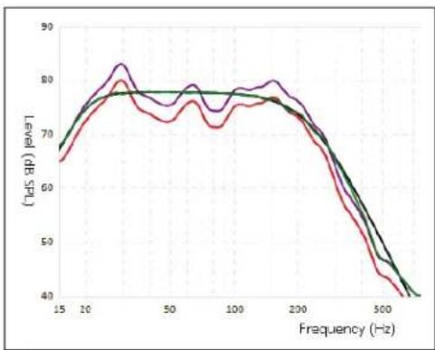
Sample curves:
line
| Frequency (Hz) | Level (dB SpO) - Red Line | Level (dB SpO) - Green Line | Level (dB SpO) - Purple Line | | -------------- | ------------------------- | --------------------------- | ---------------------------- | | 15 | 65 | 68 | 67 | | 20 | 70 | 72 | 75 | | 30 | 75 | 78 | 82 | | 50 | 72 | 78 | 78 | | 100 | 70 | 78 | 78 | | 200 | 75 | 78 | 78 | | 300 | 50 | 55 | 55 | | 500 | 40 | 45 | 45 |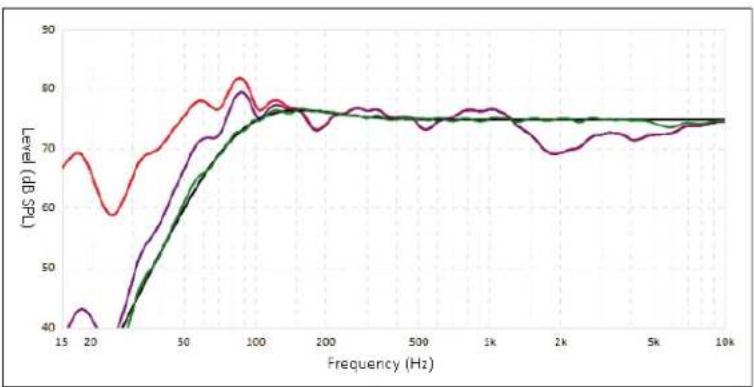
line
| Frequency (Hz) | TdS (dB) | | -------------- | -------- | | 15 | 68 | | 20 | 60 | | 50 | 75 | | 100 | 80 | | 200 | 75 | | 500 | 75 | | 1k | 75 | | 2k | 70 | | 5k | 75 | | 10k | 75 |The red curves represent the in-room response before correction, as an average from five measurement positions, whereas the green ones show response with equalization applied. In this case a subwoofer and bass management are also in use. In the subwoofer graph, which is on the left, the difference between the level of the red and purple curves shows the amount of room gain.
In addition, ARC senses where each speaker's low-frequency response naturally declines, and sets the high-pass filters to match this natural limit.
The default correction range is 5 kHz. Although it can be changed to a lower frequency if desired, raising it is not recommended. At higher frequencies the microphone becomes directional thus affecting measurement accuracy.
Note that the subwoofer graph may imply that the subwoofer plays up to the highest frequency shown, but what it plays depends on what the other channels send to it as determined by their crossover setting. The subwoofer graph shows the available correction range, which is not necessarily the range that other channels send to it through bass management.
4.1 BEFORE STARTING
Ensure that the processor software and ARC-2 software that you will be using are compatible with one another. Check www.anthemAV.com for latest versions.
PERSONAL COMPUTER VERSION OF ARC®:
- Your computer must be running Windows 7 or later and be connected to the same network as the processor, or directly to the processor with the supplied USB Mini cable.
- Depending on your network's settings, you may need to enable sharing to allow the processor to be seen by your computer.
- If you are using a laptop computer, check its power settings and battery meter to ensure that procedures will not be interrupted.
MOBILE APP VERSION OF ARC®:
- Configure the Speaker Setup menu before measurement if your speaker system does not correspond to the existing menu configuration.
BOTH VERSIONS:
- If more than one processor is on your network, each may be identified by MAC address, IP address, or the Device Name which appears in the setup menu.
- Ensure that the room will be sufficiently quiet during measurement. Typical background noise is detected and rejected with no impact on measurement accuracy but if excessive noise is present, ARC will indicate that re-measurement is required.
- If using a subwoofer, ensure that its crossover frequency dial is set to its highest frequency before measurement. ARC will manage the transition between the main speakers and subwoofer. Any adjustments to the subwoofer after measurement would require ARC to be run again.
4.2 ARC® SOFTWARE INSTALLATION
MOBILE APP VERSION:
On the iTunes store, locate Anthem ARC Mobile and install it to your device.
PERSONAL COMPUTER VERSION:
- Go to https://www.anthemav.com/support/latest-software.php
- Download the software. Depending on ARC microphone model, a support file named using the microphone's serial number may be required. If your microphone is numbered, enter its number on the web page before downloading. Be sure to enter the correct number otherwise the frequency response will be inaccurate.
- Unzip the download.
- Run setup.
To add a new numbered microphone after ARC has been installed, re-installation isn't needed - simply copy new calibration files to this directory:
(Computer, OS) C:\Program Files (x86)\Anthem Room Correction 2
During measurement, ARC will list the installed files and ask you to pick the one corresponding to the microphone in use.
What are the differences between the computer and mobile versions of ARC?
- With the phone's internal microphone there may be minor variations from ideal response. The maximum equalization frequency is restricted to 2 kHz in this case. The external dual-jack microphone using 3.5mm connection is preferred since it provides the same measurement accuracy as the main kit's USB microphone.
- The computer version allows viewing and printing curves, target curve customization, and multiple configurations for different applications that may be useful according to various sources, conditions, and preferences.
4.3 MICROPHONE STAND ASSEMBLY
If using the mobile device's microphone, skip this section.
- Loosen the tripod base screw, move the base to the bottom of the telescoping tube, re-tighten the screw.
- Screw the microphone clip to the other end of the stand. Position the clip vertically.
- Connect the USB microphone cable to the microphone and slide the microphone into the clip.
- Adjust height by first loosening the clamps on the telescoping tube and on the arm. The stand may be placed on the floor or on the seat according to whichever way puts the microphone capsule in its proper position.
4.4 MICROPHONE POSITIONING
This section mainly applies to the personal computer version and full ARC kit since the mobile app version will guide you when using the mobile device's microphone or the dual-jack microphone. The dual-jack microphone may also be used with the microphone stand and/or the PC version of ARC via USB connection.
Proper microphone positioning is essential for good results. Multiple positions are required to prevent standing waves or boundaries from skewing results.
• The microphone must point straight up.
- The microphone capsule, the listener's ears, and the speaker's acoustic center (or tweeter if in doubt) should be at approximately the same height. If the result sounds dull or bright try a different microphone height and repeat measurement.
- The first microphone position must be at or just in front of the central seating position. Speaker levels are calibrated from this position. For the remaining positions, place the microphone in the most often used parts of the listening area while ensuring that all mic positions are at least 2 feet (60 cm) apart. If there is only one listening position, positions 2 through 5 must be a circle or box around the listening chair - do not use a position more than once!
- Five different positions, and no less, are normally adequate but for larger rooms up to ten may be used.
If most or all listening positions are close to a wall:
- At least half of the microphone positions should be a minimum 2 feet (60 cm) away from the wall.
- Vary distances between microphone and wall by 1 foot (30 cm) or more, for example two or three positions can be 2 feet (30 cm) away but the remaining two or three should be at least 3 feet (90 cm) away.
In summary:
DO
- Set the mic at ear level pointing straight up.
- Use mic positions that are at least 2 feet (60 cm) apart from each other even if there's only one seating position.
- Use more than five measurement positions if using only five would result in their being more than 6 feet (2m) apart due to a large listening area.
- Start with the first measurement position in the center of the listening area.
DO NOT
- Use mic positions close to walls. If all seating positions are against the rear wall, three or more mic positions should be in front of the seating area. Vary the distance of these positions relative to the wall by 1 foot (30 cm) or more so they are not all the same distance from the wall.
4.5 MEASUREMENT
The remaining ARC instructions apply to the personal computer version. If using the mobile version, follow its instructions instead.
- Connect the microphone and the processor to the computer.
- Set the microphone in the first position. Don't stand near the microphone while sweep tones are playing otherwise, reflections from your body may cause bad measurements.
- Run Anthem Room Correction. Use Automatic mode if you are a first-time user. It will guide you through the remaining steps and at the end will load the correction data to your processor. You will still be able to change things if needed, but just remember where you're saving the .arc2 measurement file so you can find it later. The entire process takes about 5-10 minutes depending on the number of measurements and configurations.
- Up to 16 characters may be used to name a measurement. Valid ones are: a-z, A-Z, 0-9, "", "", "", "", "", <", =", >",?", and "@". The rest will be removed if used.
- Once the ARC program has completed its procedure, you can disconnect the computer.
- Save your settings in the processor's setup menu using its Save / Load Settings menu.
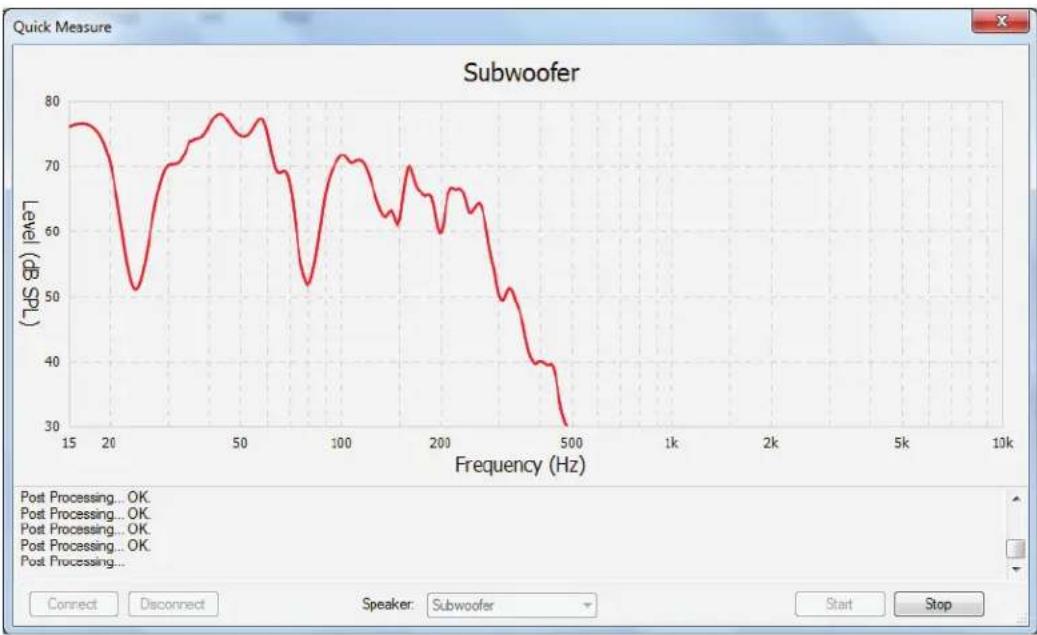
If speaker positioning is flexible, particularly for the sub, Quick Measure can help you with speaker positioning especially if an initial ARC measurement shows that there is room for improvement.
To use it, run ARC Manual mode. Click on the Quick Measure button and enable the sweep tone for the speaker that you are positioning. Note that this will reset level calibration. After a few sweeps the graph will show a live update of the uncorrected measurement. It will keep running until you turn it off. After finding good speaker positions, run the full ARC measurement.
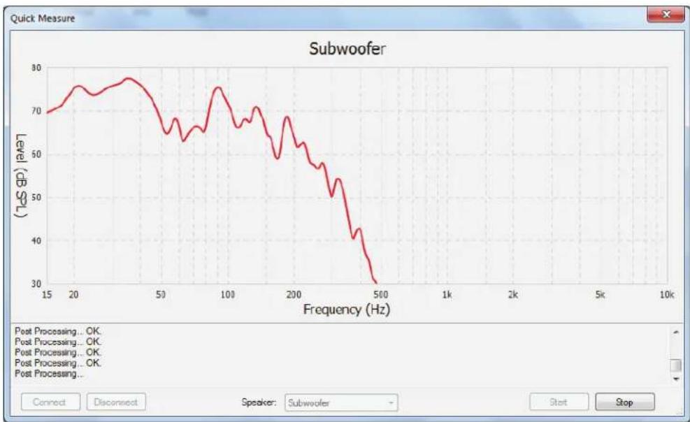
The graphs that follow show how moving a subwoofer can improve uncorrected response. Large dips like these are not uncommon:
line
| Frequency (Hz) | Level (dB SPL) | | -------------- | -------------- | | 15 | 76 | | 20 | 70 | | 25 | 52 | | 30 | 70 | | 35 | 74 | | 40 | 78 | | 45 | 76 | | 50 | 78 | | 60 | 74 | | 70 | 68 | | 80 | 52 | | 90 | 70 | | 100 | 72 | | 110 | 70 | | 120 | 68 | | 130 | 66 | | 140 | 64 | | 150 | 62 | | 160 | 60 | | 170 | 64 | | 180 | 66 | | 190 | 64 | | 200 | 62 | | 210 | 60 | | 220 | 58 | | 230 | 56 | | 240 | 54 | | 250 | 52 | | 260 | 50 | | 270 | 48 | | 280 | 46 | | 290 | 44 | | 300 | 42 | | 310 | 40 | | 320 | 38 | | 330 | 36 | | 340 | 34 | | 350 | 32 | | 360 | 30 | | 370 | 28 | | 380 | 26 | | 390 | 24 | | 400 | 22 | | 410 | 20 | | 420 | 18 | | 430 | 16 | | 440 | 14 | | 450 | 12 | | 460 | 10 | | 470 | 8 | | 480 | 6 | | 490 | 4 | | 500 | 2 |They can almost always be cured by repositioning speakers and repeating the measurement:
line
| Frequency (Hz) | Level (dB/Hz) | | -------------- | ------------- | | 15 | 70 | | 20 | 75 | | 50 | 65 | | 100 | 75 | | 200 | 60 | | 500 | 30 |4.6 MANUAL MODE AND TARGETS
When creating a new measurement, Manual and Automatic modes operate identically except that automatic mode does not require clicking on Measure, Calculate, and Upload between these stages. It also allows results to be viewed before upload, and for Targets to be edited. A file created in Automatic mode can later be opened in Manual mode.
Quick Measure
1. Measure

2. Target
3. Calculate

4. Upload
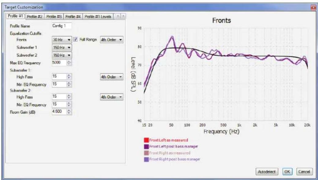
A file created in Automatic mode can be opened in Manual mode to allow target editing. After changing targets, you must click OK when closing the window to apply the settings, then Calculate. To restore original settings, click on Auto Detect then Calculate.
line
| Profile | Frequency (Hz) | | ------- | -------------- | | Front Left as measured | 15 | | Front Left post bass manager | 20 | | Front Right as measured | 50 | | Front Right post bass manager | 20 |For advice in getting the most out of your system based on your measurements, we welcome you to send your .arc2 file (please do not send screenshots) to Anthem Technical Support.
WHAT NOT TO DO
Before we get to that, something to be aware of if at first listen it appears that the equalization has reduced overall bass: It is easier to hear peaks in response than dips. ARC doesn't only level the peaks, but also the dips. With the equalization turned on it may be immediately apparent that boominess is gone, but it may take longer to notice that bass notes which were buried all along have become audible, and for this reason you might want to spend a week getting used to the new sound. Once becoming accustomed to tight bass with the entire range playing at equal level, chances are you'll never want to go back to bloated one-note bass.
If comparing ARC on vs off, note that the subwoofer's level is calibrated according to ARC being on. If ARC is then disabled, subwoofer level may need adjustment.
Viewing graphs for the first time may cause temptation to immediately change targets. There is rarely a good technical reason to do so. If you are not satisfied with initial results, examine the red pre-correction measurement curve. It shows how your system performed all along without room correction. Does this reflect the general performance expected from your speakers, especially in the bass? If not, do not try to compensate through electronic correction. It bears repeating that it is not meant at all to be a substitute for proper speaker positioning, nor can it reliably force your speakers to do something they weren't designed to do. Its purpose is to take performance to a higher level after the traditional good practices that existed before room correction have been fulfilled.
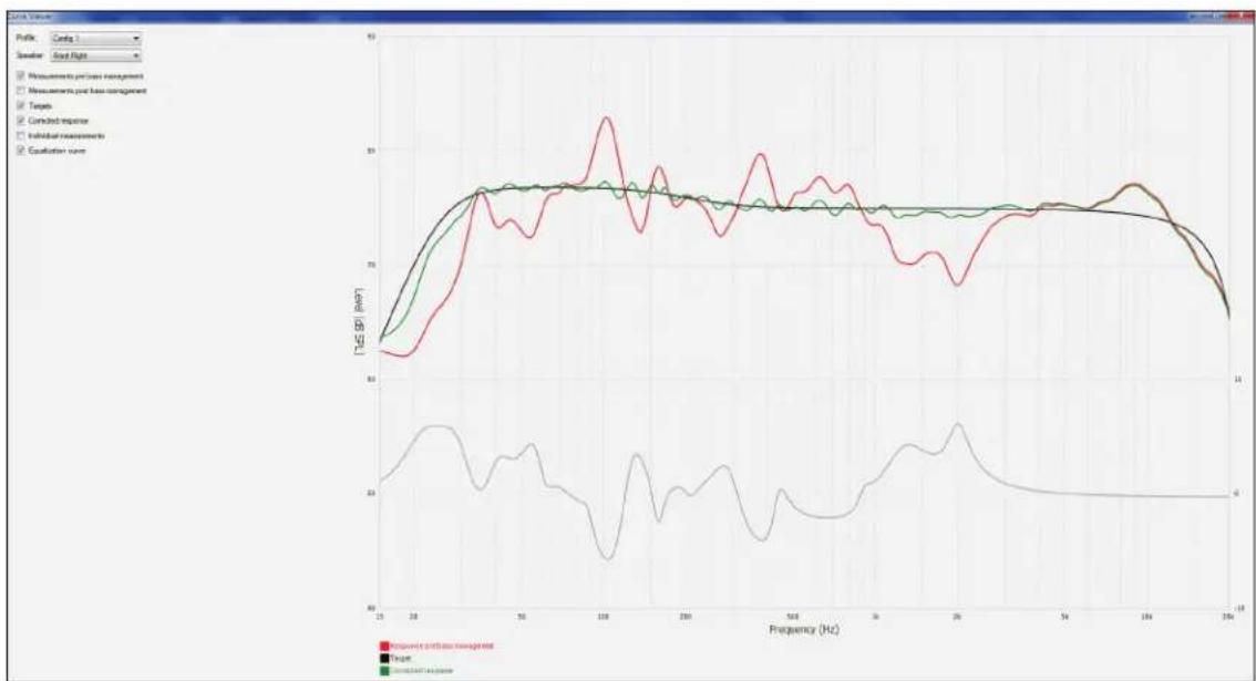
The following is a classic case of what not to do - an attempt to turn a "full-range" speaker's woofer into a subwoofer by manually lowering the equalization cutoff from 35 Hz to 25 Hz and the slope from fourth order to a more gradual third order. Such changes are very unlikely to end well. The extra stress on the speaker from approximately 20 Hz to 30 Hz could easily lead to woofer and/or crossover damage from overextension or overheating (+6 dB equates to four times the power). The amplifier will also generate more heat, something that is not good for any electronic device.
Always avoid forcing the green curve to be higher than the red or purple ones in the manner shown here:
line
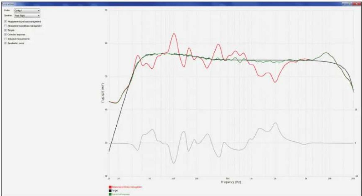
| Frequency (Hz) | Measurement and test management | Target | Controlled response | | -------------- | -------------------------------- | ------ | ------------------- | | 15 | 70 | 70 | 70 | | 20 | 75 | 75 | 75 | | 25 | 80 | 80 | 80 | | 30 | 85 | 85 | 85 | | 35 | 90 | 90 | 90 | | 40 | 95 | 95 | 95 | | 45 | 100 | 100 | 100 | | 50 | 105 | 105 | 105 | | 55 | 110 | 110 | 110 | | 60 | 115 | 115 | 115 | | 65 | 120 | 120 | 120 | | 70 | 125 | 125 | 125 | | 75 | 130 | 130 | 130 | | 80 | 135 | 135 | 135 | | 85 | 140 | 140 | 140 | | 90 | 145 | 145 | 145 | | 95 | 150 | 150 | 150 | | 100 | 155 | 155 | 155 | | 105 | 160 | 160 | 160 | | 110 | 165 | 165 | 165 | | 115 | 170 | 170 | 170 | | 120 | 175 | 175 | 175 | | 125 | 180 | 180 | 180 | | 130 | 185 | 185 | 185 | | 135 | 190 | 190 | 190 | | 140 | 195 | 195 | 195 | | 145 | 200 | 200 | 200 | | 150 | 205 | 205 | 205 | | 155 | 210 | 210 | 210 | | 160 | 215 | 215 | 215 | | 165 | 220 | 220 | 220 | | 170 | 225 | 225 | 225 | | 175 | 230 | 230 | 230 | | 180 | 235 | 235 | 235 | | 185 | 240 | 240 | 240 | | 190 | 245 | 245 | 245 | | 195 | 250 | 250 | 250 | | 200 | 255 | 255 | 255 | | 205 | 260 | 260 | 260 | | Note: The frequency in Hz is labeled as 'Frequency' and 'T-LS' (dB). The data series are extracted from the code and plotted using the plot. The labels are 'Measurement and test management', 'Target', and 'Controlled response'. The values are estimated based on the provided code.In contrast, this is the same measurement with the original targets that were automatically detected and set by ARC. Notice how the left side of the target curve complies to the speaker's natural rolloff:
line
| Frequency (Hz) | Response in data management | Target | Control response | | -------------- | ---------------------------- | ------ | ----------------- | | 20 | 48 | 48 | 48 | | 30 | 55 | 55 | 55 | | 40 | 65 | 65 | 65 | | 50 | 70 | 70 | 70 | | 60 | 75 | 75 | 75 | | 70 | 78 | 78 | 78 | | 80 | 80 | 80 | 80 | | 90 | 75 | 75 | 75 | | 100 | 70 | 70 | 70 | | 110 | 65 | 65 | 65 | | 120 | 60 | 60 | 60 | | 130 | 55 | 55 | 55 | | 140 | 50 | 50 | 50 | | 150 | 45 | 45 | 45 | | 160 | 40 | 40 | 40 | | 170 | 35 | 35 | 35 | | 180 | 30 | 30 | 30 | | 190 | 25 | 25 | 25 | | 200 | 20 | 20 | 20 | | 210 | 15 | 15 | 15 | | 220 | 10 | 10 | 10 | | 230 | 5 | 5 | 5 | | 240 | 0 | 0 | 0 | | 250 | -5 | -5 | -5 | | 260 | -10 | -10 | -10 | | 270 | -15 | -15 | -15 | | 280 | -20 | -20 | -20 | | 290 | -25 | -25 | -25 | | 300 | -30 | -30 | -30 | | 310 | -35 | -35 | -35 | | 320 | -40 | -40 | -40 | | 330 | -45 | -45 | -45 | | 340 | -50 | -50 | -50 | | 350 | -55 | -55 | -55 | | 360 | -60 | -60 | -60 | | 370 | -65 | -65 | -65 | | 380 | -70 | -70 | -70 | | 390 | -75 | -75 | -75 | | 400 | -80 | -80 | -80 | | 410 | -85 | -85 | -85 | | 420 | -90 | -90 | -90 | | 430 | -95 | -95 | -95 | | 440 | -100 | -100 | -100 | | 450 | -105 | -105 | -105 | | 460 | -110 | -110 | -110 | | 470 | -115 | -115 | -115 | | 480 | -120 | -120 | -120 | | 490 | -125 | -125 | -125 | | 500 | -130 | -130 | -130 | | 510 | -135 | -135 | -135 | | 520 | -140 | -140 | -140 | | 530 | -145 | -145 | -145 | | 540 | -150 | -150 | -150 | | 550 | -155 | -155 | -155 | | 560 | -160 | -160 | -160 | | 570 | -165 | -165 | -165 | | 580 | -170 | -170 | -170 | | 590 | -175 | -175 | -175 | | 600 | -180 | -180 | -180 | | 610 | -185 | -185 | -185 | | 620 | -190 | -190 | -190 | | 630 | -195 | -195 | -195 | | 640 | -200 | -200 | -200 | | 650 | -205 | -205 | -205 | | 660 | -210 | -210 | -210 | | 670 | -215 | -215 | -215 | | 680 | -220 | -220 | -220 | | 690 | -225 | -225 | -225 | | 700 | -230 | -230 | -230 | | 710 | -235 | -235 | -235 | | 720 | -240 | -240 | -240 | | 730 | -245 | -245 | -245 | | 740 | -250 | -250 | -250 | | 750 | -255 | -255 | -255 | | 760 | -260 | -260 | -260 | | 770 | -265 | -265 | -265 | | 780 | -270 | -270 | -270 | | 790 | -275 | -275 | -275 | | 800 | -280 | -280 | -280 | | 810 | -285 | -285 | -285 | | 820 | -290 | -290 | -290 | | 830 | -295 | -295 | -295 | | 840 | -300 | -300 | -300 | | 850 | -305 | -305 | -305 | | 860 | -310 | -310 | -310 | | 870 | -315 | -315 | -315 | | 880 | -320 | -320 | -320 | | 890 | -325 | -325 | -325 | | 900 | -330 | -330 | -330 | | 910 | -335 | -335 | -335 | | 920 | -340 | -340 | -340 | | 930 | -345 | -345 | -345 | | 940 | -350 | -350 | -350 | | 950 | -355 | -355 | -355 | | 960 | -360 | -360 | -360 | | 970 | -365 | -365 | -365 | | 980 | -370 | -370 | -370 | | 990 | -375 | -375 | -375 | | 10^+ (ref: format) I = [dB] / [dB] / [dB] / [dB] / [dB] / [dB] / [dB] / [dB] / [dB] / [dB] / [dB] / [dB] / [dB] / [dB] / [dB] / [dB] / [dB] / [dB] / [dB] / [dB] / [dB] / [dB] / [dB] / [dB] / [dB] / [dB] (ref: data management) / [reference value] / [reference value] / [reference value] / [reference value] / [reference value] / [reference value] (ref: data management) / [reference value] / [reference value] / [reference value] (ref: data management) / [reference value] / [reference value] (ref: data management) / [reference value] (ref: data management) / [reference value] (ref: data management) / [reference value] (ref: data management) / [reference value] (ref: data management) / [reference value] (ref: data management) / [reference value] (ref: data management) / [reference value] (ref: data management) / [reference value] (ref: data management) / [reference value] (ref: data management) (ref: data management) / [reference value] (ref: data management) / [reference value] (ref: data management) / [reference value] (ref: data management) / [reference value] (ref: data management) / [reference value] (ref: data management) / [reference value] (ref: data management) / [reference value] (ref: data management) / [reference value] (ref: data management) / [reference value] / [reference value] (ref: data management) / [reference value] (ref: data management) / [reference value] (ref: data management) / [reference value] (ref: data management) / [reference value] (ref: data management) / [reference value] (ref: data management) / [reference value] (ref: data management) / [reference value] (Ref: data management) / [reference value] (ref: data management) / [reference value] (ref: data management) / [reference value] (ref: data management) / [reference value] (ref: data management) / [reference value] (ref: data management) / [reference value] (ref: data management) / [reference value] (ref: data management) / [reference value] (ref: data management) / [reference value] (ref. data management) / [reference value] (ref: data management) / [reference value] (ref: data management) / [reference value] (ref: data management) / [reference value] (ref: data management) / [reference value] (ref: data management) / [reference value] (ref: data management) / [reference value] (ref: data management) / [reference value] (ref: data management) / [reference value] (ref: d Data Management) / [reference value] (ref: d Data Management) / [reference value] (ref: d Data Management) / [reference value] (ref: d Data Management) / [reference value] (ref: d Data Management) / [reference value] (ref: d Data Management) / [reference value] (ref: d Data Management) / [reference value] (ref: d Data Management) / [reference value] (ref: d Data Management) / [ Reference value] (ref: d Data Management) / [Reference value] (ref: d Data Management) / [Reference value] (ref: d Data Management) / [Reference value] (ref: d Data Management) / [Reference value] (ref: d Data Management) / [Reference value] (ref: d Data Management) / [Reference value] (ref: d Data Management) / [Reference value] (ref: d Data Management) / [Reference value] (ref: d Data Management) / [Reference value] (Ref: d Data Management) / [Reference value] (Ref: d Data Management) / [Reference value] (Ref: d Data Management) / [Reference value] (Ref: d Data Management) / [Reference value] (Ref: d Data Management) / [Reference value] (Ref: d Data Management) / [Reference value] (Ref: d Data Management) / [Reference value] (Ref: d Data Management) / [Reference value] (Ref: d Data MANAGEMENT) / [Reference value] (Ref: d Data Management) (Ref: d Data Management) (Ref: d Reference Value) (Ref: d Reference Value) (Ref: d Reference Value) (Ref: d Reference Value) (Ref: d Reference Value) (Ref: d Reference Value) (Ref: d Reference Value) (Ref: d Reference Value) (Ref: d Reference Value) (Ref: d Reference Value) (Ref: d Reference Value) (Ref: d Reference Value) (Ref: d Reference Value) (Ref: d Reference Value) (Ref: d Reference Value)MAX EQ FREQUENCY
The default correction range is 5 kHz. This may be lowered for experimentation or comparison.
ROOM GAIN
If you wish to experiment by flattening room gain, you can try it by setting this to 0 dB. Note that auto-detected room gain will be at or near 0 dB if bass absorbers are used or if the speakers are light on bass extension.
Alternatively if you would like to increase or decrease bass, this is the best place to do so if using a subwoofer since a good sub-mains transition will be maintained.
4.7 ADVANCED SUBWOOFER TARGETS
Use of these controls is recommended only for the advanced user who understands the subwoofer's capabilities and behavior when fed low frequencies at high levels. As always, check whether changes are worthwhile by listening to a variety of source material before and after modifying targets.
SUBWOOFER HIGH PASS ORDER
Change the low-end slope only if for some reason the auto-detected one doesn't match the low-end rolloff of the measured response. The left side of the red or purple measured curve is the guideline for shaping the target curve. As mentioned earlier, an attempt to use this as a means of extending low-frequency output beyond the speaker's capability will be detrimental.
SUBWOOFER HIGH PASS FREQUENCY
Use this in conjunction with High Pass Order when manually creating a curve for the lower end of the subwoofer's response.
MINIMUM SUBWOOFER EQ FREQUENCY
Change this only if you would not like for ARC to equalize the subwoofer channel below a certain frequency.
4.8 PRINTING A REPORT
To print a copy of your graphs and targets, click on Print. For a preview, click on File then Print Preview.
5.1 POWER ON / OFF AND VOLUME
During power-on and power-off a mechanical click is produced from the unit - this is normal. Volume comes on according to setup menu setting.
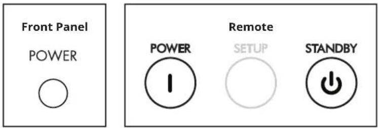
To control volume rotate the front panel knob or press VOL up/down on the remote control. To mute or un-mute the audio, press MUTE.
VOLUME
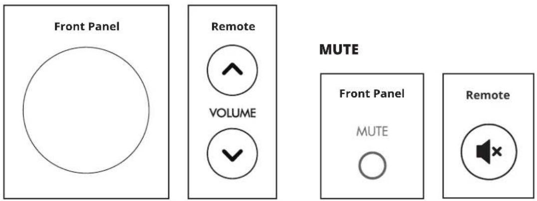
5.2 INPUT SELECTION
The number of active inputs varies according to how the Input Setup menu was programmed. To scroll through the active inputs and view them on the display, press the left/right buttons on the remote control or PREV/NEXT on the front panel.
To make the selection press SELECT.

flowchart
graph LR
    A["PREV"] --> B["NEXT"]
    B --> C["MENU/SELECT"]
    D["THEN PRESS"] --> C
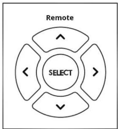
flowchart
graph TD
    A["SELECT"] --> B["Arrow Up"]
    A --> C["Arrow Down"]
    A --> D["Arrow Left"]
    A --> E["Arrow Right"]
To see the current input, press INPUT on the remote control.
5.3 LEVELS
Through this menu, subwoofer level, bass, treble, and balance can be adjusted.
Levels
Subwoofers 0.0 dB
Bass 0.0 dB
Treble 0.0 dB
Balance
Centered
To access this menu from the front panel, start by pressing MENU/SELECT.
To access this menu from the remote, start by pressing

to display this menu:
Audio Menu
Levels
Mode
After selecting Levels, press NEXT.
Cycle through the options using the up/down buttons on the remote control or the volume control on the front panel and follow the help line at the bottom of the display.
If the subwoofer(s) occasionally sounds too loud or soft according to source material, its level can be adjusted on the fly. The same can be done for tone and balance as needed.
Note that these adjustments are not meant for system calibration, which is handled in the setup menu and by Anthem Room Correction. Also note that Bass does not affect the subwoofer output, which is handled by the Level adjustment.
5.4 LISTENING MODES
Through this menu, the listening mode can be selected on the fly. Refer to the Input Setup section for a description of listening modes. If you wish, you can make a different selection after pressing MODE on the remote control or MENU/SELECT on the front panel.
Listening Mode
Stereo
Mono
Both = Left
Both = Right
To access this menu from the remote control, press MODE. The remaining steps, and access from the front panel, are similar to those in the preceding section.
5.5 INFO DISPLAY
Pressing INFO on the remote shows the input name, ARC status, input format, and listening mode on the display in addition to volume. To hide this info, press INFO again.
PHONO PREAMPLIFIER
Input Impedance 100 Ω (MC), 47 kΩ / 270 pF (MM)
RIAA Response (20 Hz - 20 kHz) ± 0.1 dB
Maximum Input
(at 1 kHz for <0.1% THD 20 Hz - 20 kHz) . . . . . . . 3.6 mV (MC), 37.7 mV (MM)
THD+N (at 1 kHz, 20 Hz - 20 kHz BW, 2 Vrms output). . 0.008% (MC), 0.005% (MM)
SNR (at 1 kHz, IEC-A, 2 Vrms output) . . . . . . . . . . . . . . . . . . . . . . . . . . . . . . . . . . . . . . . . . . . . . . . . . . . . . . . . . . . . . . . . . . 82 dB (MC), 96 dB (MM)
Gain (default at 1 kHz, user adjustable ± 20 dB) . . . . . . 55 dB (MC), 35 dB (MM)
PREAMPLIFIER
Frequency Response
digital-in, 192 kHz . . . . . . . . . . . . 10 Hz - 50 kHz (+0.00, -0.50 dB)
digital-in, 96 kHz. . . . . . . . . . . . . 10 Hz - 45 kHz (+0.00, -0.50 dB)
digital-in, 44.1 kHz . . . . . . . . . . . 10 Hz - 20 kHz (+0.00, -0.03 dB)
analog-in, DSP mode. . . . . . . . . 10 Hz - 40 kHz (+0.02, -0.20 dB)
analog-in, direct mode . . . . . . . . . 10 Hz - 80 kHz (+0.00, -0.10 dB)
THD+N (at 1 kHz, 20 Hz - 20 kHz BW, 2 Vrms output)
digital-in, 44.1 kHz, 0 dBFS . . . . . . . . . . . . . . . . . . . . . . 0.0008%
analog-in, DSP mode, 1 Vrms input . . . . . . . . . . . . . . . 0.0020%
analog-in, direct mode, 1 Vrms input. . . . . . . . . . . . . . . 0.0020%
SNR (at 1 kHz, IEC-A, 2 Vrms output)
digital-in, 44.1 kHz, 0 dBFS . . . . . . . . . . . . . . . . . . . . . . . . . . . . . . . . . . . 112 dB
analog-in, DSP mode, 2 Vrms input . . . . . . . . . . . . . . . . . . . 110 dB
analog-in, direct mode, 2 Vrms input. . . . . . . . . . . . . . . . . . 120 dB
Maximum Output (<0.1% THD) . . . . . 2.2 Vrms except analog-direct 3.3 Vrms
XLR Configuration . . . . . . . . . Pin 1: Ground, Pin 2: Normal, Pin 3: Inverted
POWER AMPLIFIER
Output (per channel, continuous, 20 Hz - 20 kHz, <1% THD)
200 W (8Ω), 400 W (4Ω), 550 W (2Ω)
THD (100 W) 0.002% (1 kHz), 0.015% (20 kHz)
IMD (100 W)
ITU-R (19 kHz + 20 kHz) 0.0007%
SMPTE (60 Hz + 7 kHz) . . . . . . . . . . . . . . . . . . . . . . . . . . . . . . . . . . . . . . 0.005%
SNR (IEC-A, ref. 200 W). 114 dB
Frequency Response (20 Hz - 20 kHz). ± 0.1 dB
Power Bandwidth (-3 dB at 200 W into 8 ohms) . . . . . . . . . . . . . . 80 kHz
Slew Rate . . . . . . . . . . . . . . . . . . . . . . . . . . . . . . . . . . . . . . . . . . . . . 30 V/μs
Damping Factor (20 Hz - 1 kHz) 330
Channel Separation 101 dB (100 Hz), 61 dB (10 kHz)
POWER REQUIREMENT
120 V version: In countries where the line voltage is 120 V, this product operates from a single phase AC power source that supplies between 108 V and 132 V at a frequency of 60 Hz.
220-240 V version: In countries where the line voltage is 220, 230, or 240 V, this product operates from a single phase AC power source that supplies between 198 V and 264 V at a frequency of 50 Hz.
POWER CONSUMPTION
Standby 0.38 W (120V), 0.45 W (240V)
Standby + Network . . . . . . . . . . . . . . . . . . . . . . . 1.1 W (120V), 1.2 W (240V)
Idle 40 W
High Output 500 W
DIMENSIONS
Height. 6-3/4" (17.2 cm)
Width 17" (43.2 cm)
Depth (not including power cord) . . . . . . . . . . . . . . . . . . . . . . . . . . . . . . . . . . . . . . . . . . . . . . . . 17-1/2" (44.5 cm)
Weight (unpacked) . . . . . . . . . . . . . . . . . . . . . . . . . . . . . . . . . . . . . . . . . . . . 40 lb (18 kg)
THE BIG PICTURE - FRONT PANEL
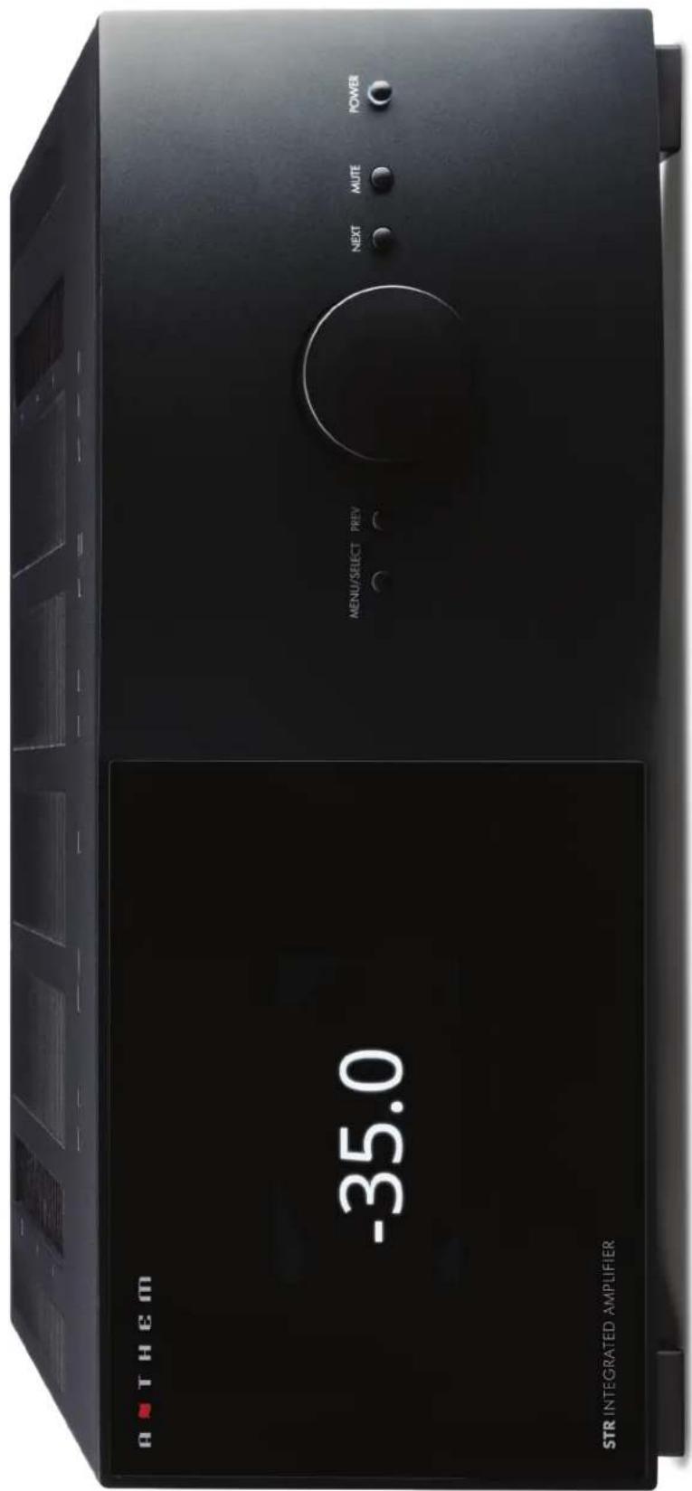
THE BIG PICTURE - REAR PANEL
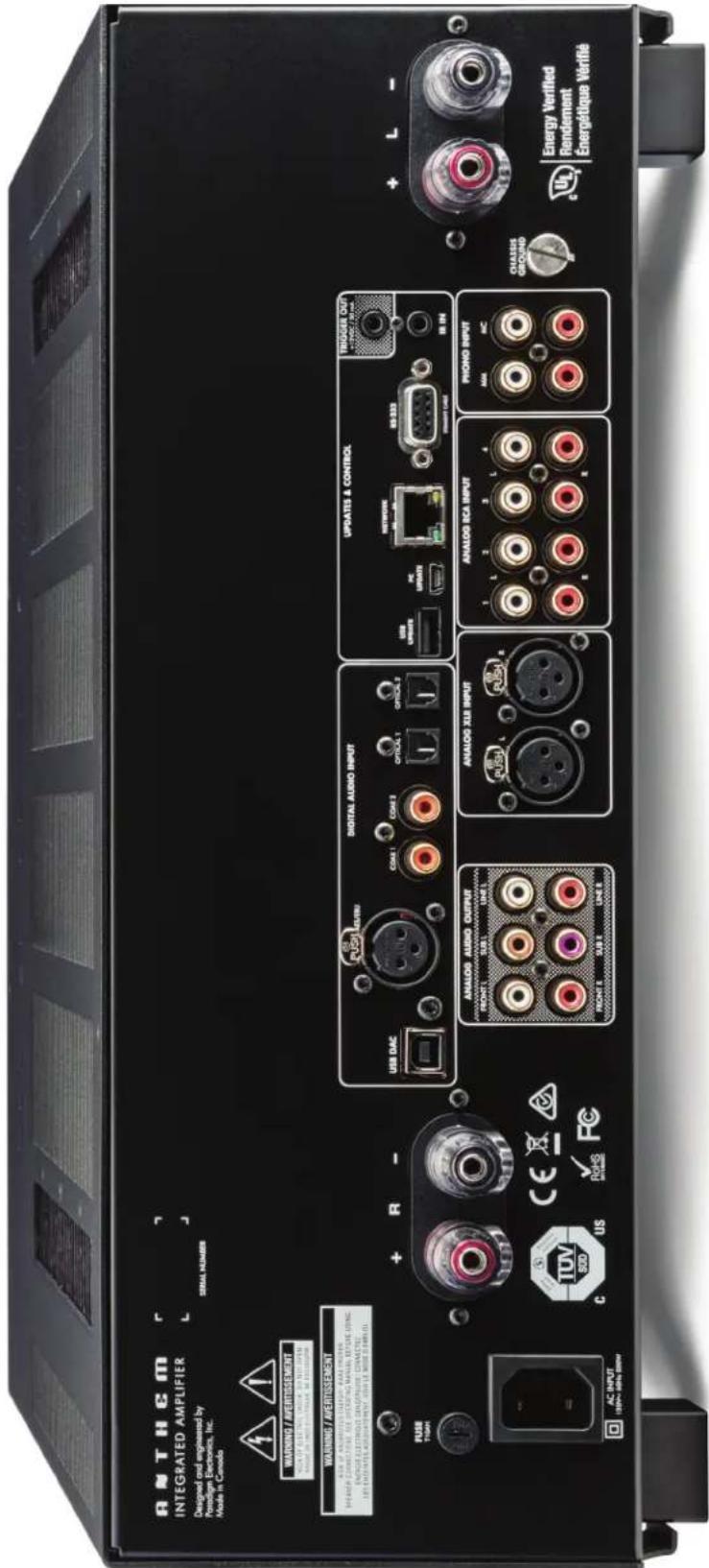
CANADA & USA
The warranty period on new Anthem products is:
5 years: Separate power amplifiers and integrated amplifiers
3 years: Audio/Video preamplifiers and receivers
Please register your product at www.anthemAV.com
The warranty period begins on the date of purchase from Anthem or an Authorized Anthem Dealer. This warranty is offered only to the original owner and is not transferable. Demonstration and display units are covered by the same warranty except that the period commences on the date of dealer invoice, not the purchaser's invoice, and cosmetic flaws are excluded.
If Anthem determines that the product has a defect in materials or manufacturing during the warranty period Anthem will at its option repair, replace or provide the necessary replacement parts without charging for parts or labor. Repaired or replaced equipment or parts supplied under this warranty are covered by the unexpired portion of the warranty.
Warranty is void if the serial number has been removed, altered or defaced, if the product has been operated, installed or handled other than in accordance with the intended application, tampered with, modified, or damaged by accident, while in transport or by failure of electric power, or has been repaired by a non-authorized party. Anthem shall have no obligation to correct any defect that is not reproducible by Anthem. If inspection by Anthem discloses that the repair required is not covered by this warranty, regular repair charges shall apply.
If a problem is discovered in your Anthem product, please contact the Authorized Anthem Dealer from whom you purchased the product. Your dealer will help to determine the cause of the problem and arrange for the appropriate action. Alternatively, follow the procedure below for factory service.
A Return Authorization (RA) number must be obtained from Anthem Technical Support before a product can be shipped to Anthem for any reason. Product shipped to Anthem without its RA Number clearly visible on the outside of the shipping carton will be refused and returned to the sender, freight collect. Product shipped to Anthem must have shipping and insurance prepaid by the sender, be packaged in the original carton and packing material and accompanied by a written description of the defect. Service will not be given under warranty without an accompanying copy of the sales invoice. Product repaired under warranty will be returned with shipping and insurance prepaid by Anthem (within Canada and continental USA only).
DISCLAIMER OF LIABILITY
Under no circumstances shall Anthem, its agents, representatives or employees assume liability or responsibility for injury or damages sustained in the use or operation of Anthem products or for damages to connected products. Some jurisdictions do not allow limitations of incidental or consequential damages so this exclusion may not apply to you.
Anthem reserves the right to make design changes without obligation to revise prior versions. All specifications are subject to change without notice.
This warranty shall be the sole and exclusive remedy to you. No other warranty or condition, statutory or otherwise, expressed or implied, shall be imposed upon Anthem nor shall any representation made by any person, including a representative or agent of Anthem, be effective to extend the warranty coverage provided herein.
On the expiration of the warranty all liability of Anthem in connection with the product shall terminate.
INTERNATIONAL
Terms and conditions are set and maintained by the Authorized Anthem Distributor, not Anthem.
A THEM®

+1 905-564-1994
www.anthemAV.com
- ANTHEM®
- STR INTEGRATED AMPLIFIER
- CAUTION
- RISK OF ELECTRIC SHOCK DO NOT OPEN
- IMPORTANT SAFETY INSTRUCTIONS
- NOTES ON ENVIRONMENTAL PROTECTION
- RECYCLING AND REUSE GUIDELINES (Europe)
- INFORMATION ABOUT COLLECTION AND DISPOSAL OF WASTE BATTERIES (DIRECTIVE 2006/66/EC OF THE EUROPEAN PARLIAMENT AND THE COUNCIL OF EUROPEAN UNION) (for European customers only)
- INTRODUCTION
- CONNECTIONS AND OPERATION
- SETUP
- ANTHEM ROOM CORRECTION (ARC™)
- OPERATION
- BEFORE MAKING CONNECTIONS
- Packing List:
- Additional items in Anthem Room Correction (ARC™) kit:
- IN-USE NOTICES
- FRONT PANEL
- REAR PANEL
- REMOTE CONTROL
- FIRMWARE UPDATES
- NO - Automatic Updates (Network Only)
- YES - Manual Updates (Network or mini-USB)
- SPEAKER CONNECTIONS
- DIGITAL INPUT CONNECTIONS
- ANALOG CONNECTIONS
- 12 VOLT TRIGGER
- INFRA RED
- POWER
- HOW TO NAVIGATE IN THE SETUP MENU
- Setup Menu
- SPEAKER SETUP
- Speaker Setup
- Speaker Edit
- PROFILE NAME
- SUBWOOFERS
- The setting options are:
- BASS MANAGEMENT
- Bass Management
- Bass Management Edit
- CROSSOVER FREQUENCY
- SUBWOOFER POLARITY AND PHASE
- LISTENER POSITION
- Listener Position
- Listener Position Edit
- Level Calibration
- Level Calibration Edit
- INPUT SETUP
- HOME THEATRE BYPASS
- Input Edit
- NAME
- INPUT JACK
- CONVERT ANALOG
- SPEAKER PROFILE
- MODE PRESET
- RUMBLE FILTER
- PHONO EQ
- ANALOG INPUT LEVELS
- Analog Input Levels
- PREFERENCES / LINE OUTPUT
- Preferences
- DISPLAY BRIGHTNESS
- FRONT PANEL WAKE-UP
- DISPLAYED INFO
- MUTE LEVEL
- MAXIMUM VOLUME
- POWER-ON VOLUME
- POWER-ON INPUT
- MUTE LINE OUT
- NETWORK / REMOTE CONTROL
- Network / Remote
- NETWORK STATUS
- DEVICE NAME
- IP CONFIGURATION
- MODE
- REAR AND FRONT IR
- GENERAL CONFIGURATION
- AUTO OFF
- STANDBY IP CONTROL
- SAVE/LOAD SETTINGS
- SAVE/LOAD USER AND INSTALLER SETTINGS
- RESET ON-THE-FLY SETTINGS
- LOAD DEFAULTS
- FACTORY RESET
- SYSTEM INFORMATION
- System Info
- FIRMWARE VERSION AND UPDATES
- Without network connection:
- With network connection:
- ARC NAME
- ARC UPLOAD TIME
- MAC ADDRESS
- USB AUDIO
- DSD PLAYBACK
- BEFORE STARTING
- PERSONAL COMPUTER VERSION OF ARC®:
- MOBILE APP VERSION OF ARC®:
- BOTH VERSIONS:
- ARC® SOFTWARE INSTALLATION
- MOBILE APP VERSION:
- PERSONAL COMPUTER VERSION:
- What are the differences between the computer and mobile versions of ARC?
- MICROPHONE STAND ASSEMBLY
- MICROPHONE POSITIONING
- DO
- DO NOT
- MEASUREMENT
- MANUAL MODE AND TARGETS
- WHAT NOT TO DO
- MAX EQ FREQUENCY
- ROOM GAIN
- ADVANCED SUBWOOFER TARGETS
- SUBWOOFER HIGH PASS ORDER
- SUBWOOFER HIGH PASS FREQUENCY
- MINIMUM SUBWOOFER EQ FREQUENCY
- PRINTING A REPORT
- POWER ON / OFF AND VOLUME
- INPUT SELECTION
- LEVELS
- Levels
- Audio Menu
- LISTENING MODES
- Listening Mode
- INFO DISPLAY
- PHONO PREAMPLIFIER
- Maximum Input
- PREAMPLIFIER
- Frequency Response
- POWER AMPLIFIER
- POWER REQUIREMENT
- POWER CONSUMPTION
- DIMENSIONS
- CANADA & USA
- DISCLAIMER OF LIABILITY
- INTERNATIONAL
Brand : Anthem
Model : STR Preamplifier
Category : Hi-Fi System