
PSS-SX01 - Car Speaker ALPINE - Free user manual and instructions
Find the device manual for free PSS-SX01 ALPINE in PDF.


| Product Type | Car Speaker (Coaxial) |
| Size | 6.5 inches (165 mm) |
| Impedance | 4 ohms |
| Power Handling (RMS) | 50 Watts |
| Power Handling (Peak) | 150 Watts |
| Frequency Response | 50 Hz - 20 kHz |
| Sensitivity | 90 dB |
| Mounting Depth | 2.5 inches (65 mm) |
| Material (Cone) | Polypropylene (PP) with Rubber Surround |
| Tweeter Type | 1-inch Silk Dome |
| Average Power Output | 25 Watts RMS per channel (recommended) |
| Functions | High-quality sound reproduction, easy installation, weather-resistant |
| Installation | Compatible with standard car speaker mounts (6.5") |
| Maintenance | Clean with dry cloth; avoid water exposure |
| Safety | Do not exceed rated power to avoid damage |
| Spare Parts | Grille, mounting hardware available separately |
| Repair Information | Contact Alpine authorized service for repairs |
| Dimensions (Speaker) | 6.5" diameter, 2.5" depth |
| Net Weight (per speaker) | 1.5 lbs (0.68 kg) |
| Warranty | 1 year limited warranty |
| Brand | Alpine |
| Model | PSS-SX01 |
Frequently Asked Questions - PSS-SX01 ALPINE
User questions about PSS-SX01 ALPINE
0 question about this device. Answer the ones you know or ask your own.
Ask a new question about this device
Download the instructions for your Car Speaker in PDF format for free! Find your manual PSS-SX01 - ALPINE and take your electronic device back in hand. On this page are published all the documents necessary for the use of your device. PSS-SX01 by ALPINE.
USER MANUAL PSS-SX01 ALPINE
Congratulations on your purchase of high quality speakers from Alpine. Your listening satisfaction is important to us. In order to maximize and maintain peak speaker performance the following guidelines are being provided. Please read this notice carefully before operating the speakers.
- Do not over-drive the amplifier. Over-driving the amplifier will result in distortion or clipping and can damage any speaker.
- Make sure gain controls are properly set. (Follow instructions in amplifier owner's manual.)
- Make sure that the speaker is properly rated for the amplifier.
- Make sure that volume, bass, treble, equalization or crossover settings do not cause the amplifier to over-drive.
Failure to follow these guidelines may result in burned or damaged speaker voice coils which will void your warranty.
If further assistance is necessary, please contact your Alpine authorized dealer.
FOR VEHICLE USE ONLY/ POUR UNE UTILISATION À L'INTÉRIEUR D'UN VÉHICULE UNIQUEMENT/SÓLO PARA VEHÍCULOS
ALPINE®
KTA-30FW
4 CHANNEL POWER AMPLIFIER
• OWNER'S MANUAL
Please read this manual to maximize your enjoyment of the outstanding performance and feature capabilities of the equipment, then retain the manual for future reference.
• MODE D'EMPLOI
1-1-8 Nishi-Gotanda, Shinagawa-ku,
Tokyo 141-8501, Japan
Phone: 81(3) 3494-1101
ALPINE ELECTRONICS MARKETING, INC.
1-7, Yukigaya-Otsukamachi, Ota-ku
Tokyo 145-0067, Japan
Tel.: 03-5499-4531
ALPINE ELECTRONICS OF AMERICA, INC.
19145 Gramercy Place
Torrance, California 90501 U.S.A.
Tel.: 1(310)326-8000
ALPINE ELECTRONICS GmbH
Naviglio (MI), Italy
Tel.:02-484781
ALPINE ELECTRONICS OF U.K., LTD.
Alpine House Earplace Business
Park.
Fletchamstead Highway,
Coventry CV4, 9TW, U.K.
Phone: 44-2476-719500
ALPINE ELECTRONICS OF
AUSTRALIA PTY. LTD.
161-165 Princes Highway, Hallam
Victoria 3803, Australia
Tel.: 03-8787-1200
ALPINE ELECTRONICS DE ESPAÑA, S.A.
Portal de Gamarra 36, Pabellón, 32
01013 Vitoria (Alava).
APDO 133, Spain
Tel.: 945-283588
ALPINE ELECTRONICS (CHINA) CO., LTD.
R2-4F, China Merchants Tower
No.116 Jianguo Street, Chaoyang
District,
Beijing 100022, China
Phone: 86(10)6566-0308



ENGLISH
Information on Disposal of Old Electrical and Electronic
Equipment and Battery (applicable for countries that have adopted separate waste collection systems)
If you want to dispose this product, do not mix it with general household waste. There is a separate collection system for used electronic products in accordance with legislation that requires proper treatment, recovery and recycling. Contact your local authority for details in locating a recycle facility nearest to you. Proper recycling and waste disposal will help conserve resources whilst preventing detrimental effects on our health and the environment.
ESPAÑOL
Please read this OWNER'S MANUAL thoroughly to familiarize yourself with each control and function. We at ALPINE hope that your new KTA-30FW will give you many years of listening enjoyment. In case of problems when installing your KTA-30FW, please contact your authorized ALPINE dealer.
CAUTION: These controls are for tuning your system. Please consult your authorized Dealer for adjustment.
| WARNING | This symbol means important instructions.Failure to heed them can result in serious injury or death. |
| CAUTION | This symbol means important instructions.Failure to heed them can result in injury or property damages. |

WARNING
- DO NOT OPERATE ANY FUNCTION THAT TAKES YOUR ATTENTION AWAY FROM SAFELY DRIVING YOUR VEHICLE. Any function that requires your prolonged attention should only be performed after coming to a complete stop. Always stop the vehicle in a safe location before performing these functions. Failure to do so may result in an accident.
- KEEP THE VOLUME AT A LEVEL WHERE YOU CAN STILL HEAR OUTSIDE NOISES WHILE DRIVING. Excessive volume levels that obscure sounds such as emergency vehicle sirens or road warning signals (train crossings, etc.) can be dangerous and may result in an accident. LISTENING AT LOUD VOLUME LEVELS IN A CAR MAY ALSO CAUSE HEARING DAMAGE.
• DO NOT DISASSEMBLE OR ALTER. Doing so may result in an accident, fire or electric shock.
- USE THIS PRODUCT FOR MOBILE 12V APPLICATIONS. Use for other than its designed application may result in fire, electric shock or other injury.
- USE THE CORRECT AMPERE RATING WHEN REPLACING FUSES. Failure to do so may result in fire or electric shock.
- DO NOT BLOCK VENTS OR RADIATOR PANELS. Doing so may cause heat to build up inside and may result in fire.
- MAKE THE CORRECT CONNECTIONS. Failure to make the proper connections may result in fire or product damage.
- USE ONLY IN VEHICLES WITH A 12 VOLT NEGATIVE GROUND. (Check with your dealer if you are not sure.) Failure to do so may result in fire, etc.
- BEFORE WIRING, DISCONNECT THE CABLE FROM THE NEGATIVE BATTERY TERMINAL. Failure to do so may result in electric shock or injury due to electrical shorts.
- DO NOT ALLOW CABLES TO BECOME ENTANGLED IN SURROUNDING OBJECTS. Arrange wiring and cables in compliance with the manual to prevent obstructions when driving. Cables or wiring that obstruct or hang up on places such as the steering wheel, gear lever, brake pedals, etc. can be extremely hazardous.
- DO NOT SPLICE INTO ELECTRICAL CABLES. Never cut away cable insulation to supply power to other equipment. Doing so will exceed the current carrying capacity of the wire and result in fire or electric shock.
- DO NOT DAMAGE PIPE OR WIRING WHEN DRILLING HOLES. When drilling holes in the chassis for installation, take precautions so as not to contact, damage or obstruct pipes, fuel lines, tanks or electrical wiring. Failure to take such precautions may result in fire.
- DO NOT USE BOLTS OR NUTS IN THE BRAKE OR STEERING SYSTEMS TO MAKE GROUND CONNECTIONS. Bolts or nuts used for the brake or steering systems (or any other safety-related system), or tanks should NEVER be used for installations or ground connections. Using such parts could disable control of the vehicle and cause fire etc.
- KEEP SMALL OBJECTS SUCH AS BOLTS OR SCREWS OUT OF THE REACH OF CHILDREN. Swallowing them may result in serious injury. If swallowed, consult a physician immediately.

CAUTION
- HALT USE IMMEDIATELY IF A PROBLEM APPEARS. Failure to do so may cause personal injury or damage to the product. Return it to your authorized Alpine dealer or the nearest Alpine Service Center for repairing.
- HAVE THE WIRING AND INSTALLATION DONE BY EXPERTS. The wiring and installation of this unit requires special technical skill and experience. To ensure safety, always contact the dealer where you purchased this product to have the work done.
- USE SPECIFIED ACCESSORY PARTS AND INSTALL THEM SECURELY. Be sure to use only the specified accessory parts. Use of other than designated parts may damage this unit internally or may not securely install the unit in place. This may cause parts to become loose resulting in hazards or product failure.
- ARRANGE THE WIRING SO IT IS NOT CRIMPED OR PINCHED BY A SHARP METAL EDGE. Route the cables and wiring away from moving parts (like the seat rails) or sharp or pointed edges. This will prevent crimping and damage to the wiring. If wiring passes through a hole in metal, use a rubber grommet to prevent the wire's insulation from being cut by the metal edge of the hole.
- DO NOT INSTALL IN LOCATIONS WITH HIGH MOISTURE OR DUST. Avoid installing the unit in locations with high incidence of moisture or dust. Moisture or dust that penetrates into this unit may result in product failure.
IMPORTANT NOTICE
This Amplifier has been type tested and found to comply with the limits for a Class B computing device in accordance with the specifications in Subpart J of Part 15 of FCC Rules. This equipment generates and uses radio frequency energy, and it must be installed and used properly in accordance with the manufacturer's instructions.
◆ For European Customers
Should you have any questions about warranty, please consult your store of purchase.
◆ For Customers in other Countries IMPORTANT NOTICE
Customers who purchase the product with which this notice is packaged, and who make this purchase in countries other than the United States of America and Canada, please contact your dealer for information regarding warranty coverage.
SERIAL NUMBER:
INSTALLATION DATE: ____
INSTALLATION TECHNICIAN: ____
PLACE OF PURCHASE: ____
IMPORTANT
Please record the serial number of your unit in the space provided here and keep it as a permanent record. The serial number plate is located on the rear of the unit.
SPECIFICATIONS
| Power Output | Ref: 14.4V, 2Ω, @ ≤1% THD+N | 75W RMS X 4 |
| Ref: 14.4V, 4Ω, @ ≤1% THD+N | 75W RMS X 4 | |
| DPP(Dynamic Peak Power) Output | Ref: 14.4V, 2Ω, @ ≤1% THD+N | ~150W RMS x 4 up to 20ms |
| Ref: 14.4V, 4Ω, @ ≤1% THD+N | ~150W RMS x 4 up to 20ms | |
| THD+N | Ref: 10W into 2Ω | <0.2% |
| Ref: Rated Power into 2Ω | <0.1% | |
| Ref: 10W into 4Ω | <0.1% | |
| Ref: Rated Power into 4Ω | <0.1% | |
| S/N Ratio | IHF A-wtd + AES-17, Ref: 1 W into 4Ω | ≥82dB |
| IHF A-wtd + AES-17, Ref: Rated Power into 4Ω | >98dB | |
| Frequency Response | +0 / -3 dB, Ref: 1 W into 4Ω | 15-36kHz |
| Input Sensitivity | Ref: Rated Power Into 4Ω, RCA | 0.2-4V |
| Ref: Rated Power Into 4Ω, Speaker | 0.5-10V | |
| Crossover | Selectable LPF/HPF @-12dB/oct(Defeatable) | 50-400Hz |
| Dimensions | Width | 233mm (9-3/16") |
| Height | 41mm (1-3/4") | |
| Depth | 95.3mm (3-3/4") | |
| Weight | 0.5kg (1.1lbs) | |
| IP rating | IP66 |
NOTE:
- For product improvement, specifications and design are subject to change without notice.
ACCESSORIES
- Input/Output/Power Wire Harness ....1
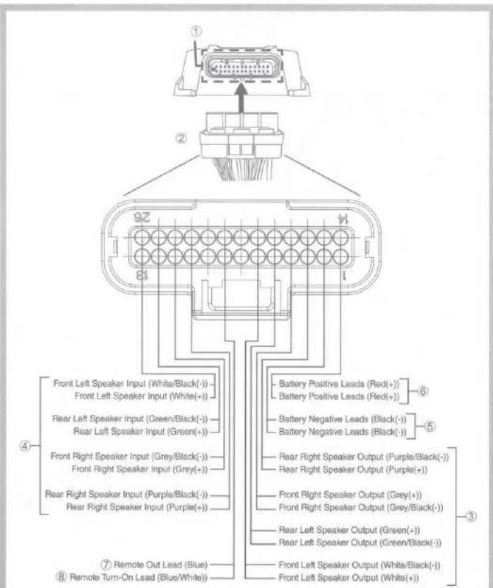
Fig. 1
CONNECTIONS (Fig. 1)
Before making connections, be sure to turn the power off to all audio components. Connect the red battery lead from the amp directly to the positive (+) terminal of the vehicle's battery. Do not connect this lead to the fuse block.
CAUTION
◆ Caution on connection terminals/parts
- Keep electrically conductive objects away from the unit's terminals/parts (power terminals, fuses, speaker output terminals, RCA connectors, etc.). Doing so prevents a possible short circuit and damage to the unit.
To prevent external noise from entering the audio system.
- Locate the unit and route the leads at least 10 cm (3-15/16") away from the car harness.
- Keep the battery power leads as far away from other leads as possible.
- Connect the ground lead securely to a bare metal spot
(remove any paint or grease if necessary) of the car chassis.
• Your Alpine dealer knows best about noise prevention
measures so consult your dealer for further information.
① Input/Output/Power Connector
② Input/Output/Power Wire Harness
③ Speaker Output Leads
Be sure to observe correct speaker output connections in the system. Connect the positive output (+) to the positive speaker terminal and the negative output (-) to the negative speaker terminal.
Note:
• Do not connect speaker leads together or to chassis ground.
④ Input Signal Leads
There are two options:
a) RCA Input Jacks (FRONT=Grey sleeve, REAR=Violet sleeve)
Connect these jacks to the line out leads on your head unit using RCA extension cables (sold separately)
b) Speaker Level Inputs
Cut off the RCA jacks, then connect the correct corresponding speaker outputs from the head unit directly to these twisted pair wires.
Note:
For the "Speaker Level Input System" setting, connecting the Remote Turn-On Lead is not required due to the "REMOTE SENSING" function of this product. However, the "REMOTE SENSING" function may not work depending on the signal source connected. In such a case, connect the Remote Turn-On Lead to an incoming power supply wire (accessory power) in the ACC position.
⑤ Ground Lead (Black)
Connect this lead securely to a clean, bare metal spot on the vehicle's chassis. Verify this point to be a true ground by checking for continuity between that point and the negative (-) terminal of the vehicle's battery. Ground all your audio components to the same point on the chassis to prevent ground loops.
⑥ Battery Lead (Red)
Connect battery lead directly to BATT + Be sure to add a 30A fuse (sold separately) as close as possible to the battery's (+) terminal.
⑦ Remote Out Lead (Blue)
Use this lead to turn on additional amplifiers.
Note:
• This is a pass through Remote Turn-On signal from the head unit.
⑧ Remote Turn-On Lead (Blue/White)
Connect this lead to the remote turn-on or power antenna (positive trigger, (+) 12V only) lead of your head unit.
KTA-30FW Right side panel/Panneau de droite/Panel derecho
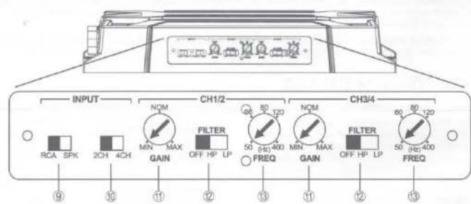
Fig. 2
SWITCH SETTINGS (Fig. 2)
⑨ Input Signal Type Switch

RCA SPK
a) Slide switch to the left position for RCA Input signals (DEFAULT setting)
b) Slide switch to the right position for speaker level input signals
⑰ Input Configuration Switch

2CH 4CH
a) Slide switch to the right position for 4 channel input (DEFAULT setting)
b) Slide switch to the left position for 2 channel input
Note:
- Input Configuration Switch should be in the left position for 2CH bridged output system.
⑪ Input Gain Adjustment Control
Set the KTA-30FW input gain to the minimum position. Using a dynamic CD as a source, increase the head unit volume until the output distorts. Then, reduce the volume 1 step (or until the output is no longer distorted).
Now, increase the amplifier gain until the sound from the speakers become distorted. Reduce the gain slightly so the sound is no longer distorted to achieve the optimum gain setting.
⑫ Filter Selector Switches

a) Slide switch to the OFF position to turn off filter.
b) Slide switch to the HP position to select high pass filter.
c) Slide switch to the LP position to select low pass filter.
⑬ Filter Frequency Adjustment Control
Adjust the filter cutoff frequency within the range of 50-400Hz.
Note:
- CH1/2 controls the front speakers and CH3/4 controls the rear speakers.
flowchart
graph TD
    A["KTA-30FW"] --> B["①"]
    B --> C["②"]
    B --> D["③"]
    B --> E["④"]
    C --> F["⑤"]
    D --> F
    F --> G["⑥"]
    G --> H["⑦"]
    H --> I["⑧"]
    style A fill:#f9f,stroke:#333
    style G fill:#f9f,stroke:#333
    style H fill:#f9f,stroke:#333
    style I fill:#f9f,stroke:#333
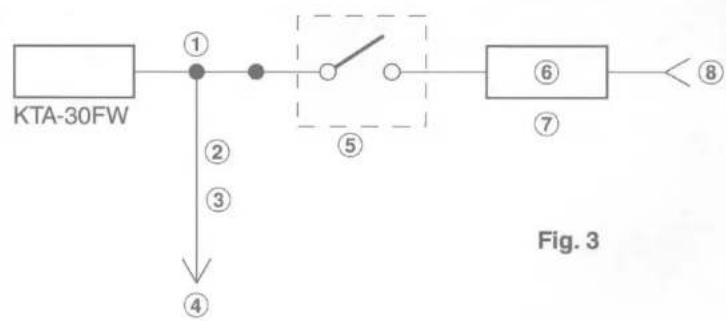
ALTERNATIVE AMPLIFIER TURN-ON OPTIONS (Fig. 3)
If your head unit does not have a traditional amplifier turn-on lead, refer to the options below for connection.
Please check your head unit for the conditions listed below: (Fig. 3)
a. The head unit does not have a remote turn-on or power antenna lead
b. The head unit's power antenna lead is activated only when the radio is on (turns off in Bluetooth or CD mode).
c. The head unit's power antenna lead is logic level output (+) 5V, negative trigger (grounding type), or cannot sustain (+) 12V when connected to other equipment in addition to the vehicle's power antenna. If any of the above conditions exist, the remote turn-on lead of your KTA-30FW must be connected to a switched power source (ignition) in the vehicle. Be sure to use a 3A fuse as close as possible to this ignition tap. Using this connection method, the KTA-30FW will turn on and stay on as long as the ignition switch is on.
If this is objectionable, a SPST (Single Pole, Single Throw) switch, in addition to the 3A fuse mentioned above, may be installed in-line on the KTA-30FW turn-on lead. This switch will then be used to turn on (and off) the KTA-30FW. Therefore, the switch should be mounted so that is accessible by the driver. Make sure the switch is turned off when the vehicle is not running. Otherwise, the amplifier will remain on and drain the battery.
① Blue/White
② Power Antenna
③ Remote Turn-On Lead
④ To other Alpine components' Remote Turn-On Leads
⑤ SPST Switch (optional)
⑥ Fuse (3A)
⑦ As close as possible to the vehicle's ignition tap
⑧ Ignition Source
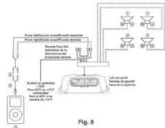
TYPICAL SYSTEM CONNECTIONS/CONNEXIONS TYPIQUES DU SYSTEME/CONEXIONES TIPICAS DEL SISTEMA
[English]
Front Lift Speaker (sois separately) Front Lift Signifier (soil) geometric
20 Front High Sputator (solid separately) 21 Rear Left Spasier (solid separately)
2) Rear Right Speaker (sold separately)
23 RCA Extension Cable (solid separately)
(2) Head Unit Speaker Connector (3) CD Head Unit
③ RCA to Mini Jack Cable (sold separately)
MP3 Player
[Français]
- Cable ports connected to HCM rail inter-phase (termab expansion)
Lactin/MP2
(Español)
flowchart
graph TD
    A["Front side panel: external terminal (current)"]
    B["Front right side panel: external terminal (current)"]
    C["Panel 1: Left panel"]
    D["Panel 2: Right panel"]
    E["Panel 3: Left panel"]
    F["Panel 4: Right panel"]
    G["Panel 5: Left panel"]
    H["Panel 6: Right panel"]
    I["Panel 7: Left panel"]
    J["Panel 8: Right panel"]
    K["Panel 9: Left panel"]
    L["Panel 10: Right panel"]
    M["Panel 11: Left panel"]
    N["Panel 12: Right panel"]
    O["Panel 13: Left panel"]
    P["Panel 14: Right panel"]
    Q["Panel 15: Left panel"]
    R["Panel 16: Right panel"]
    S["Panel 17: Left panel"]
    T["Panel 18: Right panel"]
    U["Panel 19: Left panel"]
    V["Panel 20: Right panel"]
    W["Panel 21: Left panel"]
    X["Panel 22: Right panel"]
    Y["Panel 23: Left panel"]
    Z["Panel 24: Right panel"]
    AA["Panel 25: Left panel"]
    AB["Panel 26: Right panel"]
    AC["Panel 27: Left panel"]
    AD["Panel 28: Right panel"]
    AE["Panel 29: Left panel"]
    AF["Panel 30: Right panel"]
    AG["Panel 31: Left panel"]
    AH["Panel 32: Right panel"]
    AI["Panel 33: Left panel"]
    AJ["Panel 34: Right panel"]
    AK["Panel 35: Left panel"]
    AL["Panel 36: Right panel"]
    AM["Panel 37: Left panel"]
    AN["Panel 38: Right panel"]
    AO["Panel 39: Left panel"]
    AP["Panel 40: Right panel"]
    AQ["Panel 41: Left panel"]
    AR["Panel 42: Right panel"]
    AS["Panel 43: Left panel"]
    AT["Panel 44: Right panel"]
    AU["Panel 45: Left panel"]
    AV["Panel 46: Right panel"]
    AW["Panel 47: Left panel"]
    AX["Panel 48: Right panel"]
    AY["Figure 5"]
Fig. 5
Ninofu
Sun:
Please change input
Configuration Switch
from default 40th
(1) 2024
Pie
• La patient
dmy coinvill vass
la gauche pour
une entrée à deux
合作模式
Ricola:
- 反
configueroiós de
orrada debo est
(obtocado hacia
The Ground Truth image displays a single, solid horizontal line. According to Rule 2 (UNDERSCORE & LINE RULES), this is a stylistic or background line, not a placeholder underscore. Therefore, the OCR result must ignore it and output nothing or only meaningful text. The provided OCR content is "____", which consists of four underscores. This is an incorrect interpretation of the line as a placeholder, violating the rule that stylistic lines must be ignored. The OCR has hallucinated placeholder underscores where none should exist in the GT. Hence, the OCR result is inconsistent with the Ground Truth.
He
colocado natural is insulatoria naim
una entrada de 2
cavels.
Stand Alone System/Système autonome/Sistemas autónomo
flowchart
graph TD
    A["Power Supply"] --> B["Transistors"]
    B --> C["Relays"]
    C --> D["Left and right panels"]
    D --> E["Current to geacifier"]
    E --> F["Output to inverter"]
    G["Digital display"] --> H["Ground"]
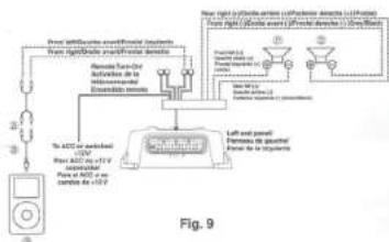
flowchart
graph TD
    A["Power Source"] --> B["Motor"]
    B --> C["Left and right panel"]
    C --> D["Left and right panel with 120V power supply"]
    C --> E["Left and left panel with 120V power supply"]
    C --> F["Left and right panel with 120V power supply"]
    C --> G["Left and right panel with 120V power supply"]
    C --> H["Left and left panel with 120V power supply"]
    C --> I["Left and right panel with 120V power supply"]
    C --> J["Left and left panel with 120V power supply"]
    C --> K["Left and right panel with 120V power supply"]
    C --> L["Left and left panel with 120V power supply"]
    C --> M["Left and right panel with 120V power supply"]
    C --> N["Left and left panel with 120V power supply"]
    C --> O["Left and right panel with 120V power supply"]
    C --> P["Left and left panel with 120V power supply"]
    C --> Q["Left and right panel with 120V power supply"]
    C --> R["Left and left panel with 120V power supply"]
    C --> S["Left and right panel with 120V power supply"]
    C --> T["Left and left panel with 120V power supply"]
    C --> U["Left and right panel with 120V power supply"]
    C --> V["Left and left panel with 120V power supply"]
    C --> W["Left and right panel with 120V power supply"]
    C --> X["Left and left panel with 120V power supply"]
    C --> Y["Left and right panel with 120V power supply"]
    C --> Z["Left and left panel with 120V power supply"]
    C --> AA["Left and right panel with 120V power supply"]
和
例三
Please change input
Configuration Switch
from default 4th to
von
(No text)
[Non-Text]
Remonique :
• La valeur
store store
As geuven
site next
表决结果:
[Non-Text]
No
• El/interrugior de
configuración de
amada deo os
codicada Nicos la updateda nara
- Cut off the RCR jacks
and connect the head
unit speaker write
directly to the KOA 3054: first writes.
(3) 47 Paper Works
Потвартная
- Congratulations on purchasing the PSS-SX01. This installation manual is designed to give you an overview of how to install the PSS-SX01. Please familiarize yourself with the owners manual before attempting the installation. If you still have additional questions please call 1-800-TECH-101.
Note
● Design and specifications are subject to change without notice for improvement.
To Ensure Safe Use, Always Follow These Precautions
● The installation of this product requires specialized skills and experience. We recommend that you have the product installed by an Alpine authorized dealer.
- Before you use this product, be sure to carefully read this installation manual and the separate user's manual so that you can use the product correctly. Alpine Electronics bears no responsibility for problems that arise as a result of failure to follow the instructions in the manuals.
- This manual includes a number of symbols that are intended to help you use the product safely, to prevent harm to you and others, and to protect against damage to property. These symbols and their meanings are listed below. Make sure you fully understand these symbols before you begin reading the main text.
Explanations of Injury and Damage That May Result from Incorrect Use
| (DAX) Warning | Ignoring the content marked by this indication and using the product incorrectly is expected to lead to death or serious injury. |
| (YCB1) Caution | Ignoring the content marked by this indication and using the product incorrectly is only expected to lead to injury or property damage. |
Types of Precautions
 Forbidden Forbidden | Indicates actions that are forbidden (must not be performed) |
 Forbidden Forbidden | Indicates that disassembly is forbidden. |
 Mandatory Mandatory | Indicates actions that are mandatory (must be performed) |
 | Marks content that should receive your full attention. |

Warning
Do not disassemble or modify the product. Doing so could lead to an accident, fire, or electric shock.

Forbidden
Store screws and other small objects where children cannot reach them. If one of those small objects is swallowed, consult with a doctor immediately.

When replacing fuses be sure to use the fuses with the specified current rating. Failing to do so could lead to an accident or fire.


Mandatory Forbidden
Only connect the product to a 12 VDC negative ground car. Failing to do so could lead to an accident or fire.

Mandatory
Do not cut the insulation on a cord and take power from another device. Doing so could lead to fire or electric shock.

Forbidden
Do not install the product in a location where it will obstruct the driver's forward view; interfere with the operation of the steering wheel, gear shift, or the like; or pose a threat to passengers. Doing so could lead to an accident or injury.

Forbidden
When making a hole in the vehicle body, be careful to avoid damaging pipes, the fuel tank, electrical wiring, and the like. This kind of damage could lead to an accident or fire.

When installing and grounding the product, do not use any of the bolts or nuts of the steering wheel, brakes, fuel tank, or the like. Doing so could make the brakes stop working or could lead to fire.

Forbidden
Do not install the product near the passenger-side airbag. Doing so could interfere with the operation of the airbag and lead to an accident or injury.

Forbidden
Bundle cords so that they don't interfere with driving. Wrapping cords around the steering wheel, gearshift, brake pedal, or the like could lead to an accident or damage equipment.


Caution
Connect the product properly according to the instructions. Failing to do so could lead to fire or an accident.

Forbidden
Do not sandwich cords between the seat railing or allow them to touch protrusions. Resulting breaks or shorts could lead to electric shock or fire.

Do not block vents or heat sinks. Doing so could lead to fire or damage equipment.

Use the accessories according to the instructions, and attach them securely. Failing to do so could lead to an accident or damage equipment.

Forbidden
Do not install the product where it may be exposed to water or in a place with high levels of humidity or dust. Doing so could lead to fire or damage equipment.

Forbidden
The installation and wiring of this product requires specialized skills and experience. Have the product installed by an Alpine authorized dealer.

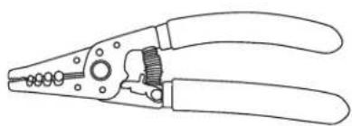
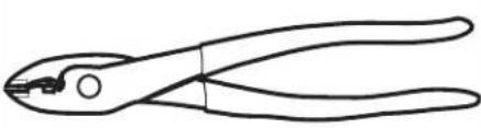
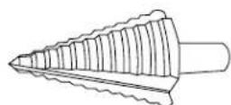
Tools Potentially Needed
| Wire Strippers Wire Cutters Step Drill Bit | ||
 |  |  |
| Socket Set With 19mm Socket Extension Ratchet | ||
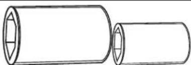 |  |  |
| Phillips Screwdriver Torx Bits Air Saw | ||
 | 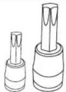 | 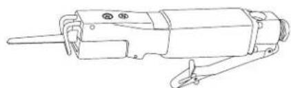 |
| Panel Removal Tools Wire Fishing Tool Cordless Power Drill | ||
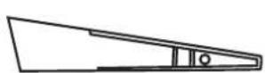 | 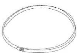 | 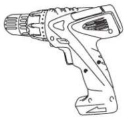 |
| Digital Multimeter Flathead | Screwdriver | |
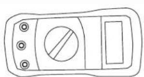 |  | |
Accessory List
| SPV-65-SXS Pod With Speaker x 2 | KTA-30FW 4-Channel Amplifier KTX-BT100 Bluetooth Adapter | |
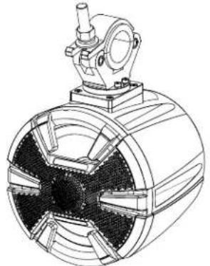 | 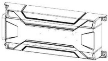 | 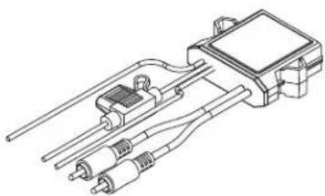 |
| 90 Degree Speaker Terminal Front Logo Badge x 2 Rear Logo Badge x 2 | ||
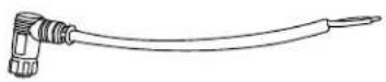 |  |  |
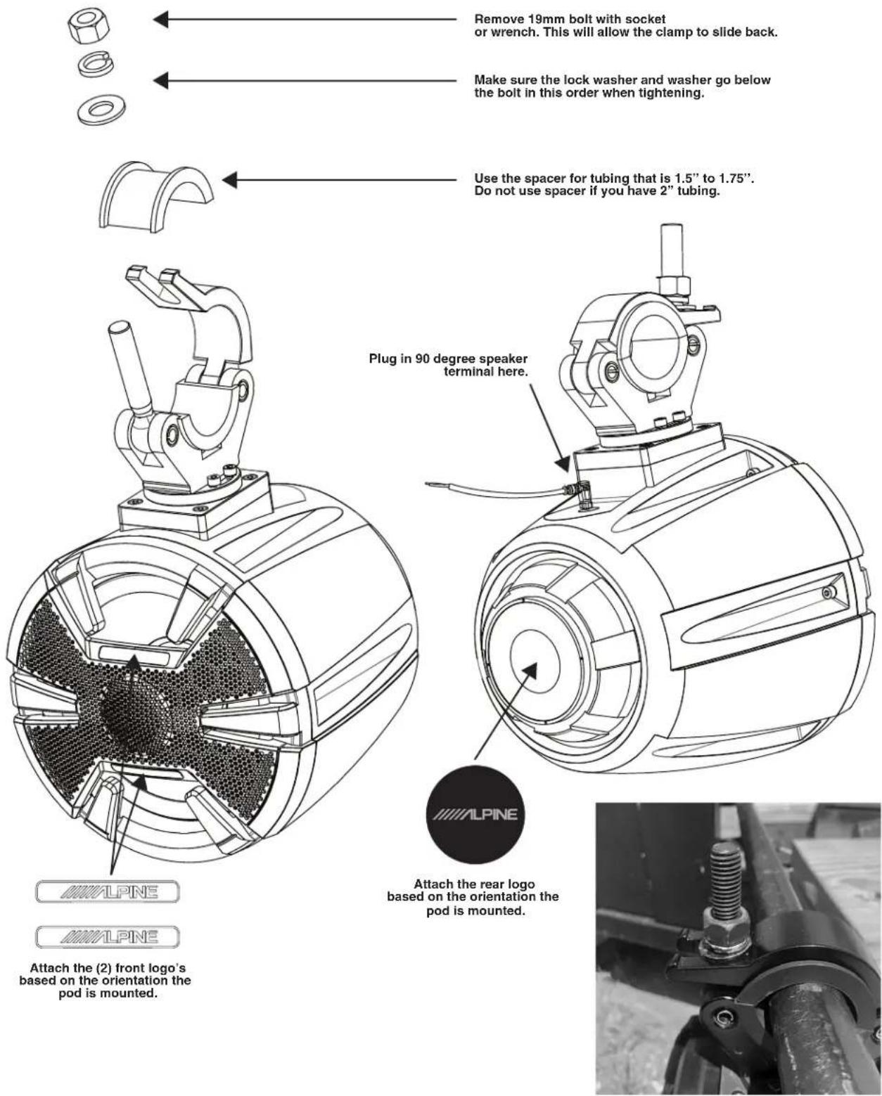
Mounting The Speaker Pod Exploded View
Bluetooth Module Connections
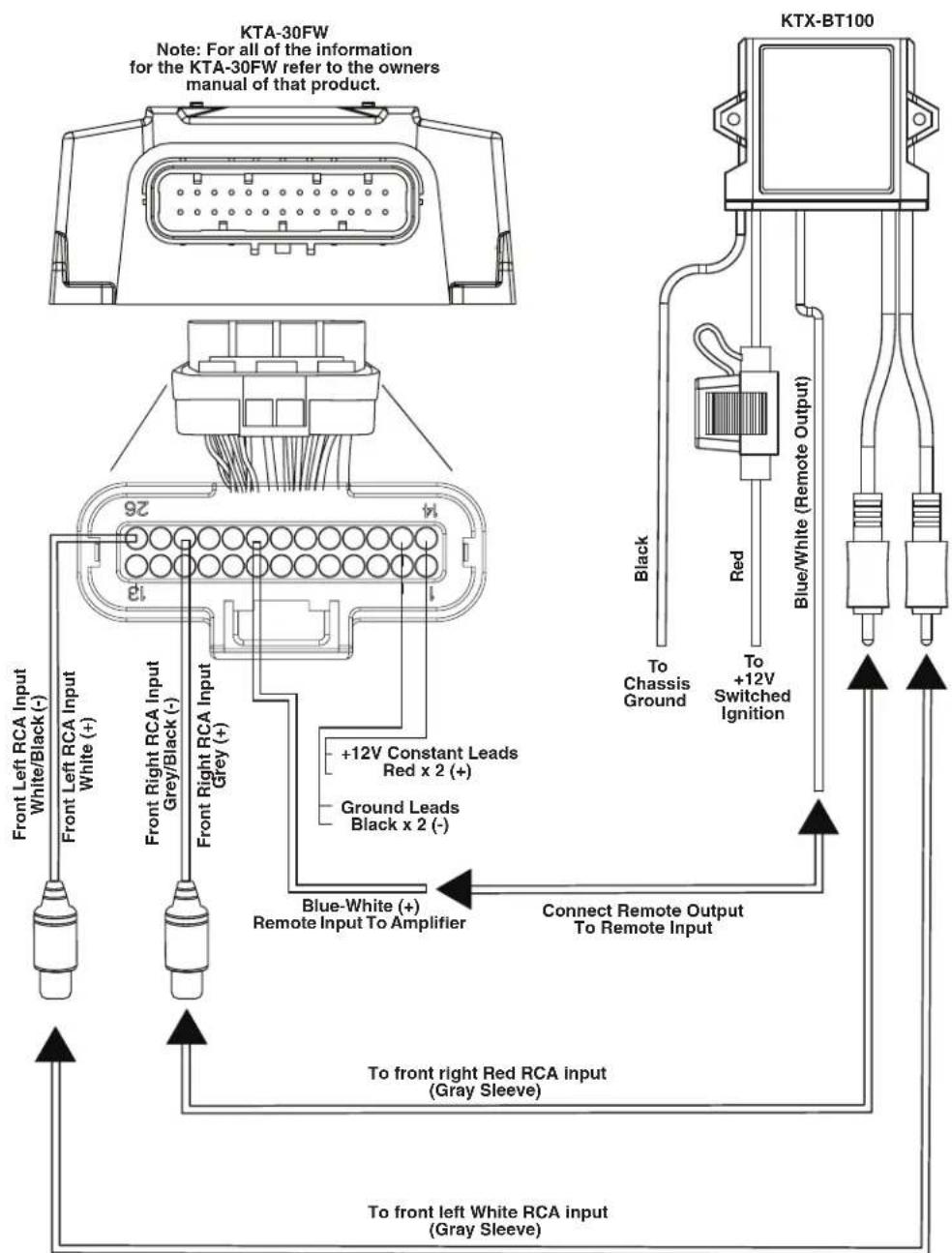
flowchart
graph TD
    A["Front Left RCA Input White/Black (-)"] --> B["Blue-White (+)"]
    C["Front Left RCA Input White (+)"] --> D["Blue/White (Remote Output)"]
    E["Front Right RCA Input Grey/Black (-)"] --> F["Blue/White (Remote Output)"]
    G["Front Right RCA Input Grey (+)"] --> H["Blue/White (Remote Output)"]
    I["Ground Leads Black x 2 (-)"] --> J["Connect Remote Output To Remote Input"]
    K["Ground Leads Red x 2 (+)"] --> L["+12V Constant Leads"]
    M["Chassis Ground"] --> N["To Switched Ignition"]
    O["Red"] --> P["To Switched"]
    Q["To red"] --> R["To black"]
    S["To white"] --> T["To black"]
    U["To left white RCA input (Gray Sleeve)"] --> V["To right white RCA input (Gray Sleeve)"]
    W["Note: For all of the information for the KTA-30FW refer to the owners manual of that product."] --> X["KTA-30FW"]
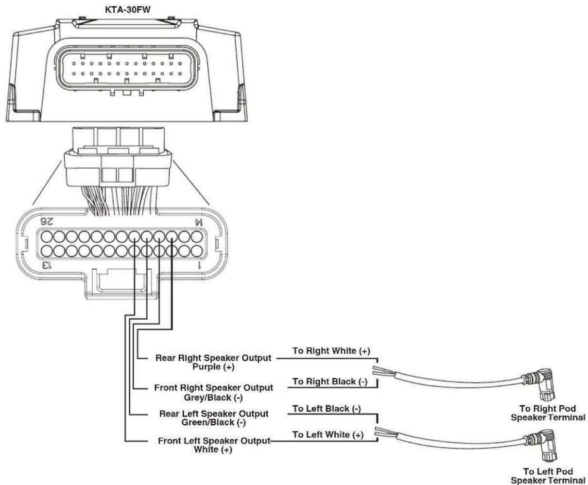
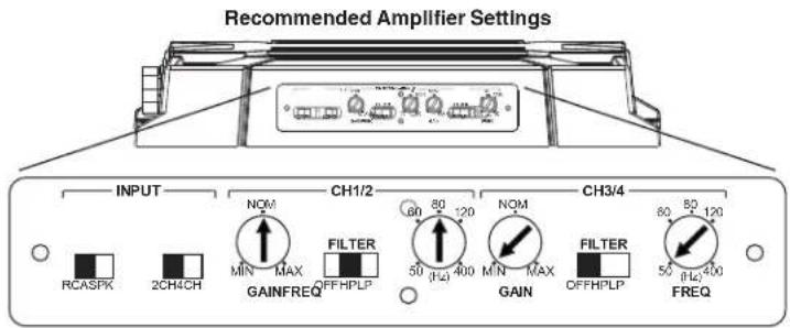
Bridging The Amplifier
How To Pair Phone
1 Open the settings menu of the phone.
2 Go to the Bluetooth settings and make sure it's turned on.
3 Scan for devices.
4 The phone will find KTX-BT100.
5 Select KTX-BT100 on the phone to pair to it.
Specifications
| Continuous Power Handling (RMS) | 90W |
| Woofer Size 6-1/2” | |
| Nominal Impedance 4 Ohms | |
| Frequency Response 50-22kHz | |
| Voice Coil Resistance (Re) 3.6 Ohms | |
| Free Air Resonance (Fs) 49 Hz | |
| Efficiency 87.8 dB @ 1 W / 1m | |
| Electrical “Q” (Qes) .61 | |
| Mechanical “Q” (Qms) 11.19 | |
| Total Speaker “Q” (Qts) .57 | |
| Equivalent Compliance (Vas) 20 17 Liters | |
| Moving Mass (Mms) 14.22 | |
| Mechanical Compliance (Cms) 73 5.84 mm/N | |
| Magnetic Strength (BL) | 5.13 T-m |
| Effective Piston Area (Sd) | 21.5 sq in |
| One Way Linear Excursion (Xmax) | 4.9mm |
| IP Rating | IP55 |
Dimensions
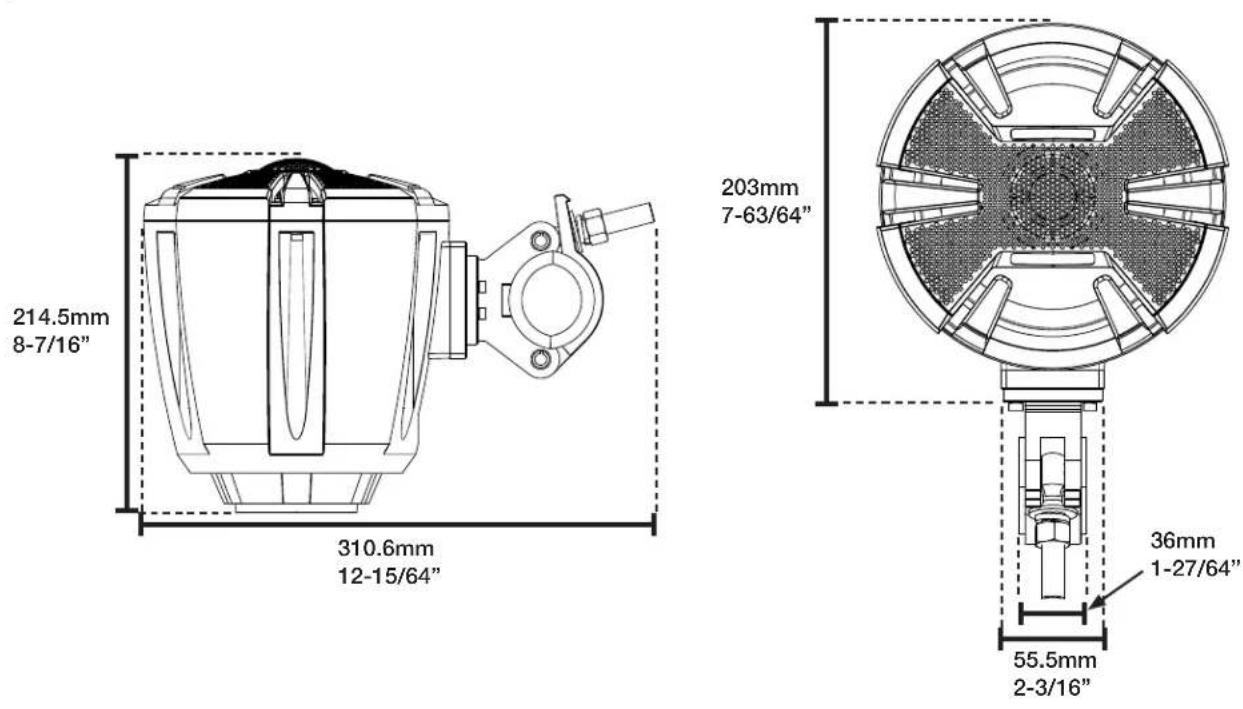
Troubleshooting Guide
| Symptom Possible Cause Remedy | |||
| 1 | System will not turn on. | Missing or blown fuse at the battery. | Insert or replace fuse. |
| Amp's Remote Turn-On wire may be disconnected. | Use a digital multimeter on the Blue/White remote wire to ensure it gets +12V positive when the audio system is on. If not trace the wire and correct the connection. | ||
| Amp +12V constant wire not getting voltage. | Test the Yellow +12V constant wire with a digital multimeter to ensure it is getting +12V at all times. Trace the wire to the fused battery source. | ||
| 2 | Output is low. | Amplifier gain is not adjusted properly. | Adjust the gain to where it should be according to your specific system setup. |
| Signal input to the amp is not good. | Use a known good RCA input into the amplifier to see if that works. | ||
| 3 | One of the speakers is not working. | Disconnected pin or loose connection. | Check all connections to the speaker, loose pins, disconnected terminals etc.. Swap around the speakers for the working one to see if that works. |
| Amp channel not installed properly. | Swap the left and right RCA's to see if the other side works. If so the installation of the other amp channel needs to be gone over. | ||
natural_image
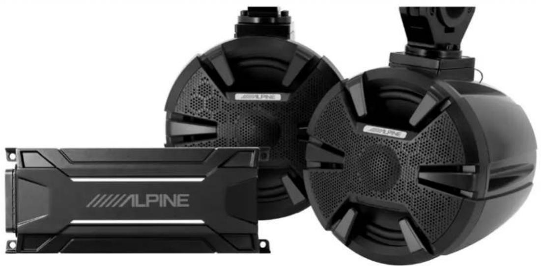
Exterior view of three black ALPINE audio equipment modules with visible speaker covers and ventilation grilles (no text or symbols on main components)PRODUCT OVERVIEW
This complete sound system combines the premium sound you've come to expect from Alpine as well as a unique design that will complement the look of your Side-by-Side. As an easy add-on for any existing Side-by-Side with 1.5"-2" rails, the PSS-SX01 includes everything you need for an exciting music experience, including two enclosed 6.5-inch speakers, a grille-mounted, 1-inch teteron dome tweeter, and one 4-channel amplifier all weather-resistant against the elements.
*Additional speaker and power wire may be required for installation
natural_image
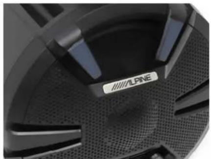
Close-up of a black automotive wheel rim with visible branding (no text or symbols beyond logo)PRODUCT FEATURES
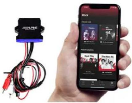
Music on Your Adventures – Stream music directly from your smartphone without a radio or head unit source with the included Bluetooth® adaptor.
Flexible Installation – With universal folding-style clamps that fit 1.5-2" rails, the PSS-SX01 can be installed in just about any Side-by-Side or UTV.
Built for the Elements – The weather-resistant speakers and amplifier can withstand all of the elements for an uninterrupted music experience.
GO BEYOND UTILITY
PRODUCT DETAILS
WHAT'S INCLUDED:
• 6.5" 2-Way Mid Bass Drivers
• KTA-30FW 4-Channel Weather-Resistant Tough
Power Pack Amplifier
- KCX-BT01 Weather-Resistant Bluetooth® Adaptor
• ASA 978 B+ Fiberglass Speaker Pod with Folding-Style Clamp
SPEAKERS:
• Enclosed 6.5" 2-Way Speakers
• 1" Teteron Dome Tweeter
• Rated IP55 Weather-Resistant
- Steel Frame
AMPLIFIER:
- Alpine's Class D Amplifier with Dynamic Peak Power (DPP)
• 4-Channel Power Pack Amplifier
• Rated IP66 Weather-Resistant
BLUETOOTH ADAPTER:
• 12V Weather-Resistant Bluetooth® Adaptor
- Complete Wireless Connections Bluetooth® 4.0
• Built-In Line Driver for 3x Voltage Output
• Music Signal Remote Trigger Output
SPEAKER PODS:
• ASA 978 B+ Fiberglass
• Pro-Style Folding Style Clamp that will fit 1.5"-2" Rails.
- Rotating Coated Aluminum Base
• 90-Degree Plug with 20AWG Pigtail
• Rated IP65 Weather-Resistant
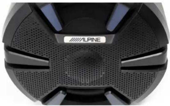
SPEAKER SPECS
• Material: Santoprene
• Frequency Response: 50Hz - 22kHz
• Power Handling: 90W RMS / 225W Peak
• Nominal Impedence: 4Ω
• Voice Coil Diameter: 25 mm
natural_image
Close-up of a black and white electronic device with ventilation grilles and a logo reading 'ALPINE' (no readable text or symbols beyond branding)AMPLIFIER SPECS
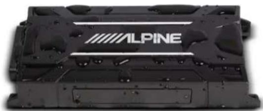
• CTA-2006-B Compliant
- 75W RMS × 4 (2Ω/4Ω, 14.4V, 1% THD+N)
• 150W DPP x 4 (2Ω/4Ω, 14.4V, 1% THD+N)
- Amplifier 2ch/4ch input (selectable)
• 85dB S/N (ref. 1W into 4Ω)
• >0.01% THD (ref. 1W into 4Ω)
• 20-20kHz Frequency response (+/- 1dB)
- Speaker/RCA inputs (Selectable, High range=0.5-10V, Low range=0.2-4V)
- Sound Control: Crossovers: Off/Hp/Lp, Fc=50-400Hz @ -12dB/Oct. (variable) Input gain settings (variable); 2ch/4ch input (selectable)
natural_image
Close-up of a black industrial battery pack labeled 'ALPINE' (no additional text or symbols visible)LIMITED WARRANTY
ALPINE ELECTRONICS OF AMERICA, INC. ("Alpine"), is dedicated to quality craftsmanship and is pleased to offer this Warranty. We suggest that you read it thoroughly. Should you have any questions, please contact your Dealer or contact Alpine at one of the telephone numbers listed below.
●PRODUCTS COVERED:
This Warranty covers Car Audio Products and Related Accessories ("the product"). Products purchased in the Canada are covered only in the Canada. Products purchased in the U.S.A. are covered only in the U.S.A.
●LENGTH OF WARRANTY:
This Warranty is in effect for one year from the date of the first consumer purchase on most with the exception of the INA-W900/INA-W900BT, which is two years.
●WHO IS COVERED:
This Warranty only covers the original purchaser of the product, who must reside in the United States, Puerto Rico or Canada.
WHAT IS COVERED:
This Warranty covers defects in materials or workmanship (parts and labor) in the product.
WHAT IS NOT COVERED:
This Warranty does not cover the following:
① Damage occurring during shipment of the product to Alpine for repair (claims must be presented to the carrier).
② Damage caused by accident or abuse, including burned voice coils caused by over-driving the speaker (amplifier level is turned up and driven into distortion or clipping). Speaker mechanical failure (e.g. punctures, tears or rips). Cracked or damaged LCD panels. Dropped or damaged hard drives.
③ Damage caused by negligence, misuse, improper operation or failure to follow instructions contained in the Owner's manual.
④ Damage caused by act of God, including without limitation, earthquake, fire, flood, storms or other acts of nature. Any cost or expense related to the removal or reinstallation of the product.
⑤ Service performed by an unauthorized person, company or association.
⑥ Any product which has the serial number defaced, altered or removed.
⑦ Any product which has been adjusted, altered or modified without Alpine's consent.
⑧ Any product not distributed by Alpine within the United States, Puerto Rico or Canada.
⑨ Any product not purchased from an Authorized Alpine Dealer.
●HOW TO OBTAIN WARRANTY SERVICE:
① You are responsible for delivery of the product to an Authorized Alpine Service Center or Alpine for repair and for payment of any initial shipping charges. Alpine will, at its option, repair or replace the product with a new or reconditioned product without charge. If the repairs are covered by the warranty, and if the product was shipped to an Authorized Alpine Service Center or Alpine, Alpine will pay the return shipping charges.
② You should provide a detailed description of the problem(s) for which service is required.
③ You must supply proof of your purchase of the product.
④ You must package the product securely to avoid damage during shipment. To prevent lost packages it is recommended to use a carrier that provides a tracking service.
●HOW WE LIMIT IMPLIED WARRANTIES:
ANY IMPLIED WARRANTIES INCLUDING FITNESS FOR USE AND MERCHANTABILITY ARE LIMITED IN DURATION TO THE PERIOD OF THE EXPRESS WARRANTY SET FORTH ABOVE AND NO PERSON IS AUTHORIZED TO ASSUME FOR ALPINE ANY OTHER LIABILITY IN CONNECTION WITH THE SALE OF THE PRODUCT.
●HOW WE EXCLUDE CERTAIN DAMAGES: ALPINE EXPRESSLY DISCLAIMS LIABILITY FOR INCIDENTAL AND CONSEQUENTIAL DAMAGES CAUSED BY THE PRODUCT. THE TERM "INCIDENTAL DAMAGES" REFERS TO EXPENSES OF TRANSPORTING THE PRODUCT TO THE ALPINE SERVICE CENTER, LOSS OF THE ORIGINAL PURCHASER'S TIME, LOSS OF THE USE OF THE PRODUCT, BUS FARES, CAR RENTALS OR OTHERS COSTS RELATING TO THE CARE AND CUSTODY OF THE PRODUCT. THE TERM "CONSEQUENTIAL DAMAGES" REFERS TO THE COST OF REPAIRING OR REPLACING OTHER PROPERTY WHICH IS DAMAGED WHEN THIS PRODUCT DOES NOT WORK PROPERLY. THE REMEDIES PROVIDED UNDER THIS WARRANTY ARE EXCLUSIVE AND IN LIEU OF ALL OTHERS.
●HOW STATE/PROVINCIAL LAW RELATES TO THE WARRANTY:
This Warranty gives you specific legal rights, and you may also have other rights which vary from state to state and province to province. In addition, some states/provinces do not allow limitations on how long an implied warranty lasts, and some do not allow the exclusion or limitation of incidental or consequential damages. Accordingly, limitations as to these matters contained herein may not apply to you.
●IN CANADA ONLY:
This Warranty is not valid unless your Alpine car audio product has been installed in your vehicle by an Authorized Installation Center, and this warranty stamped upon installation by the installation center.
●HOW TO CONTACT CUSTOMER SERVICE:
Should the product require service, please call the following number for your nearest Authorized Alpine Service Center.
CUSTOMER SERVICE 1-800-421-2284, ext. 860304 TECH SUPPORT 1-800-TECH-101 (1-800-832-4101)
Or visit our website at; http://www.alpine-usa.com
Thank you for choosing Alpine for your car audio equipment needs. Our goal is to produce the best audio/video/navigation products in the world and hope your expectations are met.
Please take a moment to protect your purchase by registering your product now at the following address: www.alpine-usa.com/registration. You will be informed of product and software updates (if applicable), special promotions, and news about Alpine.
By registering your product, you will also have a chance to participate in exclusive offers to win Alpine gear.
We look forward to continue serving you in the future.

Sincerely,
The Alpine Team
French
- FOR VEHICLE USE ONLY/ POUR UNE UTILISATION À L'INTÉRIEUR D'UN VÉHICULE UNIQUEMENT/SÓLO PARA VEHÍCULOS
- ALPINE®
- KTA-30FW
- CHANNEL POWER AMPLIFIER
- ALPINE ELECTRONICS MARKETING, INC.
- ALPINE ELECTRONICS OF AMERICA, INC.
- ALPINE ELECTRONICS GmbH
- ALPINE ELECTRONICS OF U.K., LTD.
- ALPINE ELECTRONICS OF
- AUSTRALIA PTY. LTD.
- ALPINE ELECTRONICS DE ESPAÑA, S.A.
- ALPINE ELECTRONICS (CHINA) CO., LTD.
- ENGLISH
- ESPAÑOL
- WARNING
- CAUTION
- IMPORTANT NOTICE
- ◆ For European Customers
- ◆ For Customers in other Countries IMPORTANT NOTICE
- IMPORTANT
- NOTE:
- ACCESSORIES
- CONNECTIONS (Fig. 1)
- SWITCH SETTINGS (Fig. 2)
- ALTERNATIVE AMPLIFIER TURN-ON OPTIONS (Fig. 3)
- TYPICAL SYSTEM CONNECTIONS/CONNEXIONS TYPIQUES DU SYSTEME/CONEXIONES TIPICAS DEL SISTEMA
- [English]
- [Français]
- (Español)
- Ninofu
- Sun:
- Pie
- Ricola:
- He
- 和
- Remonique :
- No
- Потвартная
- Note
- To Ensure Safe Use, Always Follow These Precautions
- Bluetooth Module Connections
- Bridging The Amplifier
- How To Pair Phone
- PRODUCT OVERVIEW
- PRODUCT FEATURES
- PRODUCT DETAILS
- WHAT'S INCLUDED:
- SPEAKERS:
- AMPLIFIER:
- BLUETOOTH ADAPTER:
- SPEAKER PODS:
- SPEAKER SPECS
- AMPLIFIER SPECS
- LIMITED WARRANTY
- ●PRODUCTS COVERED:
- ●LENGTH OF WARRANTY:
- ●WHO IS COVERED:
- WHAT IS COVERED:
- WHAT IS NOT COVERED:
- ●HOW TO OBTAIN WARRANTY SERVICE:
- ●HOW WE LIMIT IMPLIED WARRANTIES:
- ●HOW STATE/PROVINCIAL LAW RELATES TO THE WARRANTY:
- ●IN CANADA ONLY:
- ●HOW TO CONTACT CUSTOMER SERVICE:
- French
Brand : ALPINE
Model : PSS-SX01
Category : Car Speaker