E6510 - Screen Avocor - Free user manual and instructions
Find the device manual for free E6510 Avocor in PDF.


| Product Type | Interactive Flat Panel Display |
| Brand | Avocor |
| Model | E6510 |
| Screen Size | 65 inches (diagonal) |
| Resolution | 3840 x 2160 (4K UHD) |
| Brightness | 350 cd/m² |
| Touch Technology | Infrared (IR) touch, up to 20 touch points |
| Input Ports | HDMI (3), USB (2), VGA, Audio In, RS232, LAN |
| Output Ports | HDMI, Audio Out, USB (Touch) |
| Power Supply | AC 100-240V, 50/60Hz |
| Power Consumption (Typical) | 200 W |
| Standby Power | < 0.5 W |
| Dimensions (W x H x D) with Stand | 1500 x 900 x 100 mm |
| Weight (with Stand) | 35 kg |
| VESA Mount | 600 x 400 mm |
| Operating Temperature | 0°C to 40°C |
| Storage Temperature | -20°C to 60°C |
| Panel Type | LED-backlit LCD |
| Touch Surface | Anti-glare, tempered glass |
| Cleaning Instructions | Wipe with a soft, dry cloth. Avoid liquids and abrasive cleaners. |
| Safety Instructions | Use a grounded outlet. Do not cover ventilation slots. Keep away from heat sources. |
| Spare Parts & Repairability | Contact Avocor support for spare parts. Service should be performed by authorized technicians. |
| Included Accessories | Power cable, HDMI cable, USB cable, remote control, stylus pens (2) |
| Warranty | 3 years (standard) |
Frequently Asked Questions - E6510 Avocor
User questions about E6510 Avocor
0 question about this device. Answer the ones you know or ask your own.
Ask a new question about this device
Download the instructions for your Screen in PDF format for free! Find your manual E6510 - Avocor and take your electronic device back in hand. On this page are published all the documents necessary for the use of your device. E6510 by Avocor.
USER MANUAL E6510 Avocor
natural_image
Three large black-framed display screens with abstract blue wave patterns and a C-series logo on the screen (no readable text or symbols beyond branding)AVE Series
Quick Start Guide
AVE-6510, AVE-7510, AVE-8610
E Series Quick Start Guide Table of Contents
- Contents of Packaging
- The Display at a Glance
- Display Input Sources
- The Remote Control
- Switching the display on and off Source Selection Connecting to the Display
- Connecting to an external PC using a HDMI connection
- Connecting to an external PC using a DisplayPort connection
- Enabling the Touch System
- Installing an OPS Module
- Warranty Support
Contents of Packaging
1. Accessory Carton
- Quick Start Guide
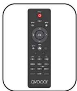
• Remote Control & Batteries
• 2x Touch Stylus - 1x3mm & 1x6mm - Eraser
• Power Cables - UK Cable 2m & European Cable 2m
• 2x 3m HDMI Cable
• 2x 3m USB-A - USB-A Cable - Cleaning Cloth
- Pen Holder
natural_image
Black remote control device with 'civocor' branding and control buttons (no readable text beyond branding)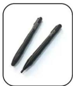
natural_image
Two black pen-like pens with engraved markings, isolated on white background (no text or symbols)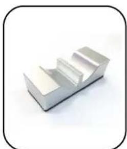
natural_image
3D rendered metallic object with three stepped surfaces, no text or symbols visible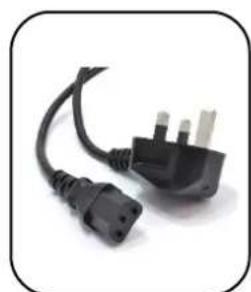
natural_image
Close-up of a black electrical outlet plug with three leads (no text or symbols visible)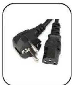
natural_image
Close-up of two black electrical power plug connectors (no text or symbols visible)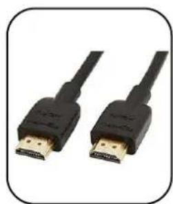
natural_image
Two black USB connectors with gold connector, shown in side profile (no text or symbols visible)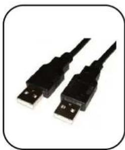
natural_image
Two black USB connectors with white leads, shown against a plain white background (no text or symbols visible)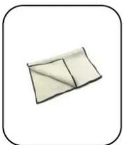
natural_image
Simple illustration of a folded or folded object with no text or symbols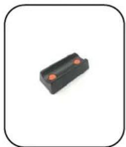
natural_image
Black rectangular electronic component with two orange leads, enclosed in a rounded square frame (no text or symbols)Please visit www.avocor.com to download the full E-Series user manual and the Pen Aware Touch Drivers.
The Display at a Glance
Front View
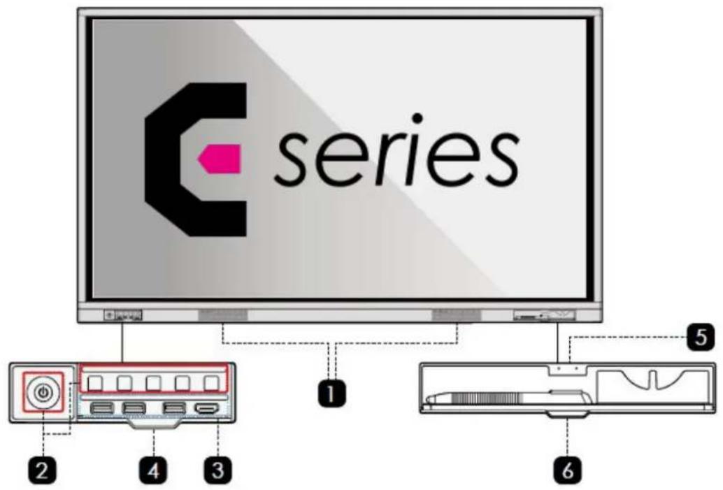
Rear View
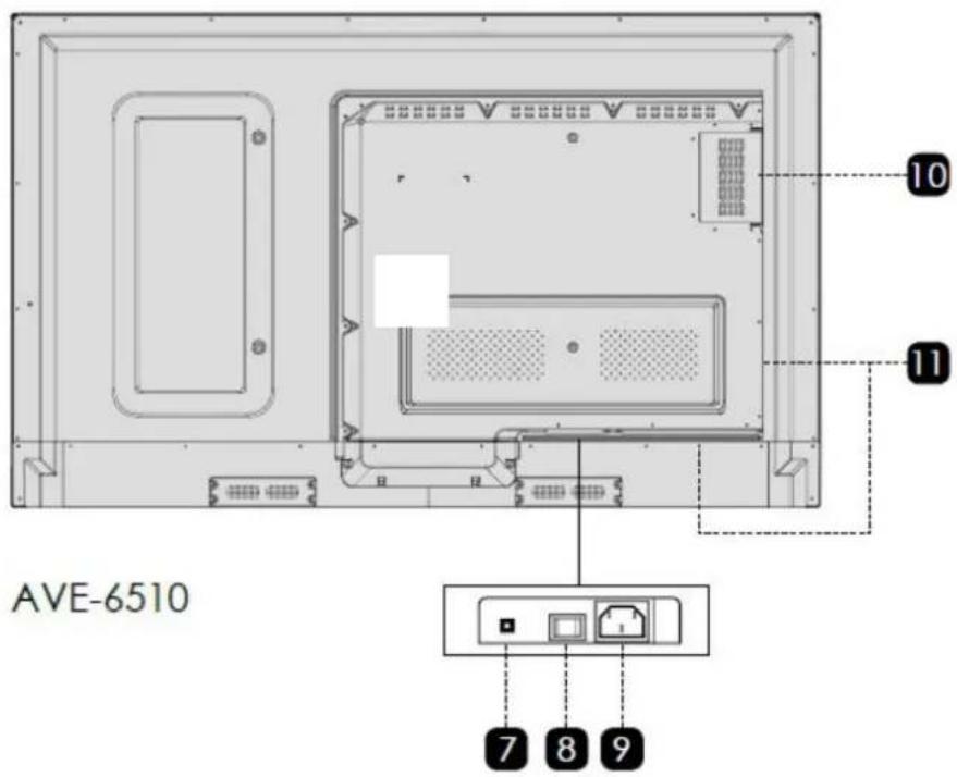
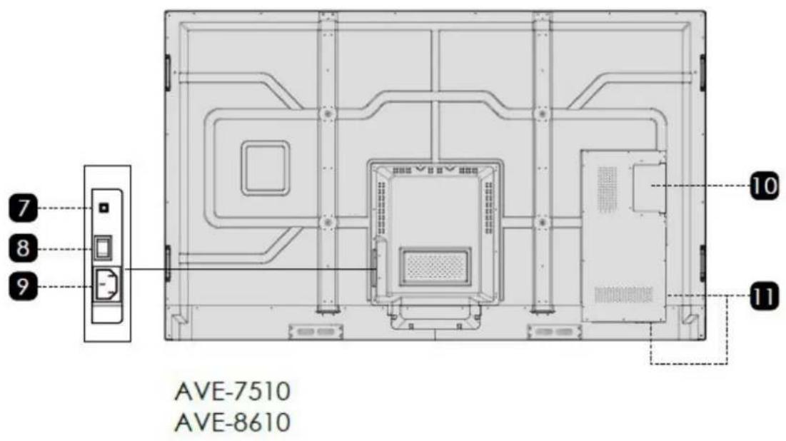
1 Speakers
3 Front Ports
5 Pen/Eraser Tray
7 Reset Button
9 Power Supply
11 Rear Ports
2 Front Buttons
4 Button Cover
6 Pen/Eraser Tray Cover
8 Power Switch
10 OPS PC Slot
Front Buttons
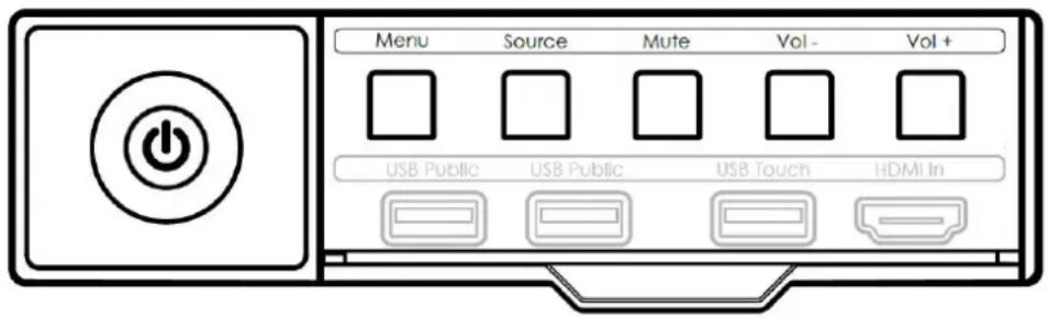
| Button | Operation | Function |
| Power Short Press | Power on/off IndicatorLED status:Solid Red : Sleep modeSolid Green : Working stateBlinking Red and Green : Standby mode | |
| Menu | Short press | Open the Settings menu |
| Source | Short press | Open the Source menu |
| Mute | Short press | Mutes the audio |
| VOL - | Short press | Decrease the audio volume in steps |
| Long press - more than 1 sec | Decrease the sound volume continuously | |
| VOL+ | Short press | Increase the audio volume in steps |
| Long press - more than 1 sec | Increase the sound volume continuously | |
E-Series Display Inputs
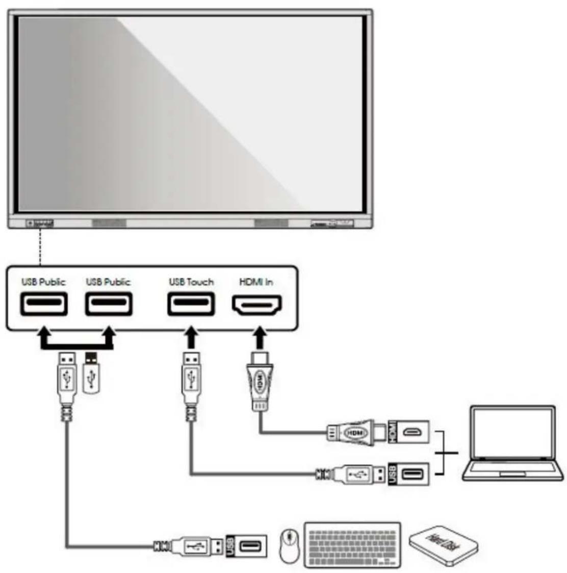
Front Ports
flowchart
graph TD
    A["Computer"] --> B["USB Public"]
    A --> C["USB Public"]
    A --> D["USB Touch"]
    A --> E["HDMI In"]
    B --> F["USB Device 1"]
    C --> G["USB Device 2"]
    D --> H["USB Device 3"]
    E --> I["USB Device 4"]
    F --> J["Laptop"]
    G --> J
    H --> J
    I --> J
    J --> K["USB Device 5"]
    K --> L["User Interface"]
    L --> M["Mac OS"]
Rear Ports
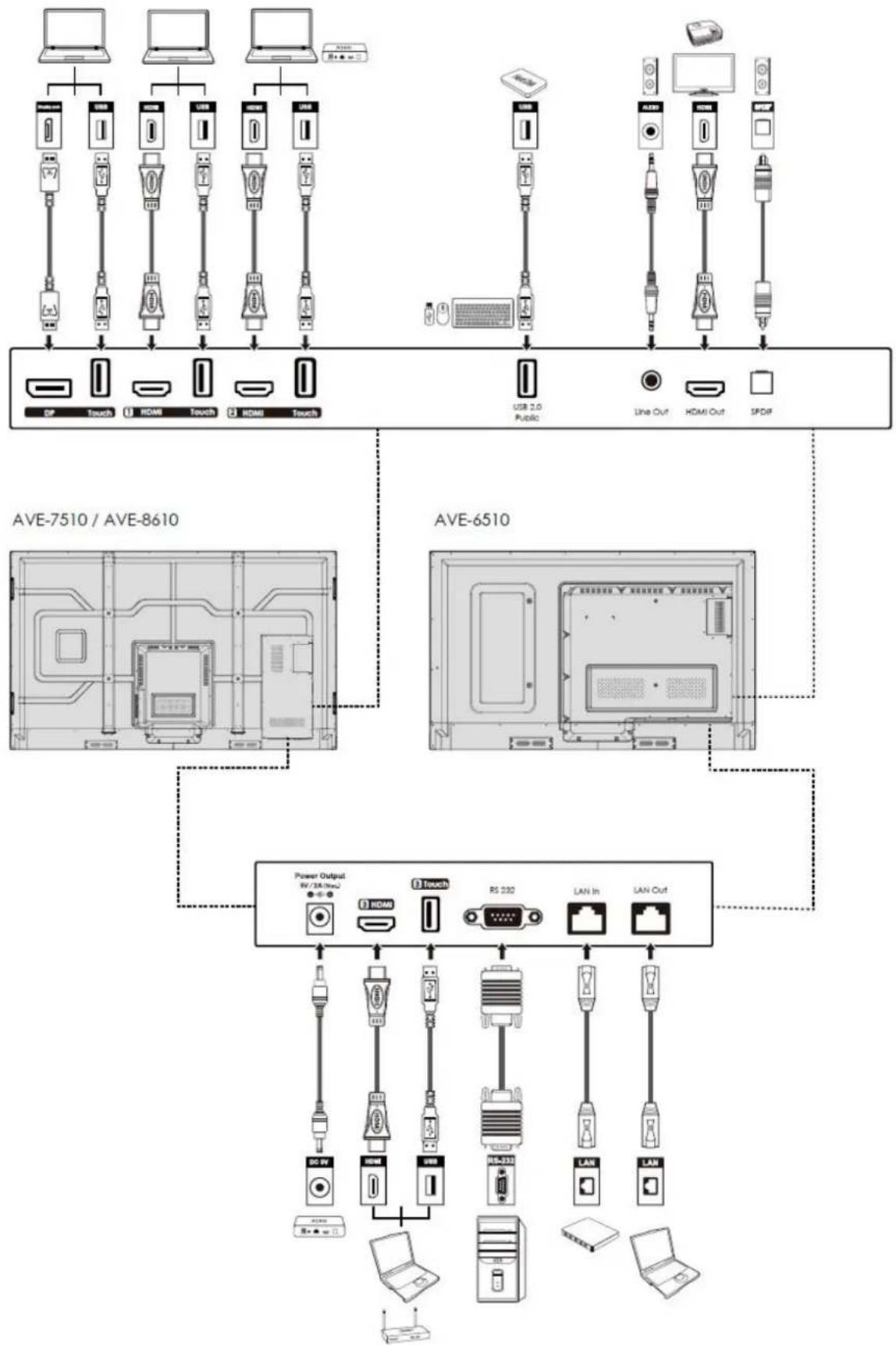
flowchart
graph TD
    subgraph AVE-7510 / AVE-8610
        A1["User"] --> B1["Touch"]
        A2["User"] --> B2["HDMI"]
        A3["User"] --> B3["Touch"]
        A4["User"] --> B4["HDMI"]
        A5["User"] --> B5["Touch"]
        B1 --> C1["USB 2.0 Public"]
        B2 --> C2["Line Out"]
        B3 --> C3["HDMI Out"]
        B4 --> C4["SPDIF"]
    end

    subgraph AVE-6510
        D1["User"] --> E1["Touch"]
        D2["User"] --> E2["HDMI"]
        D3["User"] --> E3["Touch"]
        D4["User"] --> E4["HDMI"]
        D5["User"] --> E5["Touch"]
        E1 --> F1["Power Output RV/2A/HzC"]
        E2 --> F2["Power Output RV/2A/HzC"]
        E3 --> F3["Power Output RV/2A/HzC"]
        E4 --> F4["Power Output RV/2A/HzC"]
        E5 --> F5["Power Output RV/2A/HzC"]
        F1 --> G1["Switch"]
        F2 --> G2["Switch"]
        F3 --> G3["Switch"]
        F4 --> G4["Switch"]
        F5 --> G5["Switch"]
        G1 --> H1["LAN In"]
        G2 --> H2["LAN In"]
        G3 --> H3["LAN In"]
        G4 --> H4["LAN In"]
        G5 --> H5["LAN In"]
        H1 --> I1["Power Output"]
        H2 --> I2["Power Output"]
        H3 --> I3["Power Output"]
        H4 --> I4["Power Output"]
        H5 --> I5["Power Output"]
    end

    subgraph AVE-7510 / AVE-8610
        I1 --> J1["Switch"]
        I2 --> J2["Switch"]
        I3 --> J3["Switch"]
        I4 --> J4["Switch"]
        I5 --> J5["Switch"]
    end
Remote Control
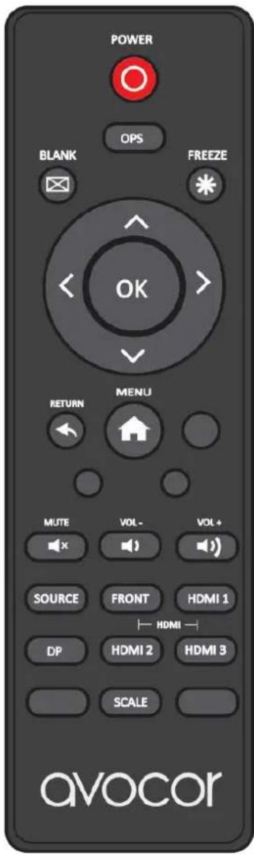
| Label | Description |
 | Turns the display on and off. |
 | Select the OPS PC source. |
 | Blanks the display. Press again to restore. |
 | Freezes the display. Press again to restore. |
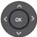 | Navigates through menus and settings.Selects highlighted menu choice |
 | When the menu system is already open, pressing this button will close the on screen menu. |
 | Opens the display menu system. |
 | Mutes the audio. Pressing Mute again restores the audio |
 | Decreases the Volume by pressing the - key |
 | Increases the Volume by pressing the + key |
 | Opens the Source Menu. |
 | cts DisplayPort |
 | Selects the HDMI Sources |
 | |
 | Selects each aspect ratio, in sequence: Full Screen, Auto, Pillar Box |
Switching the Avocor display on and off
Switching on
- Plug the end of the supplied power cord into side of the display
- Connect the other end to the power source.
- Turn on the main power switch at the side of the display. The power LED indicator lights Red to indicate that the display is in "standby" mode.
- Press the Power button and the power LED indicator on the left-hand side of the display will then light up in green, which tells you that the screen is switched on.
- After a brief warm-up period, the display will display an image
Switching off
- Switch the display off by pressing the Power button on the display.
- The display will then cycle and shut down.
Selecting the Source
You can access several sources on the Avocor E-Series display including, HDMI, DisplayPort, & OPS.
The Source button is located on the Connect & Control Bar or on the Remote Control. Once the menu has been selected, you will see the option to select the source you require.
HDMI 1, HDMI 2, HDMI 3, DisplayPort, OPS, & Front HDMI
If there is no active signal from the chosen source, the screen will display the following message: "No Signal".
Connecting the Display
Proceed as follows to connect the display to your video sources, external controller.
When connecting your equipment:
- Turn off all equipment before making any connections.
- Use the correct signal cables for each source.
- For best performance and to minimise cable clutter, use high-quality cables that are only as long as necessary to connect two devices. (Don't use a cable longer than 5 metres).
- Ensure that the cables are securely connected.
Connecting to an external PC using a HDMI connection
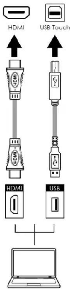
In addition to a HDMI connection, a USB touch connection is required when connecting an external PC.
- Connect the enclosed HDMI cable to the HDMI port of the touchscreen and to the external PC.
- Connect the enclosed USB cable to the corresponding touch USB port (USB-A) of the touchscreen and to the USB port (USB-A) on the external PC.
- Using the Remote Control select the HDMI source button or press the Source Button (see operating buttons) on the Front Connection bar to select HDMI.
This display supports the VESA Display Data Channel (DDC) standard. This standard provides "Plug and Play" capability; the display and a VESA DDC-compatible computer communicate their setting requirements, allowing for quick and easy setup.
In order for Plug and Play to work correctly, you must turn on the display before you turn on the connected computer.
We recommend using a USB cable that is no longer than 5 metres.
Connecting to an external PC using a DisplayPort connection
In addition to a DisplayPort connection, a USB touch connection is required when connecting an external PC.
- Connect a DisplayPort cable to the DisplayPort port of the touchscreen and to the external PC.
- Connect the enclosed USB cable to the touch USB port (USB-A) of the touchscreen and to the USB port (USB-A) on the external PC.
- Using the Remote Control select the DisplayPort source button or press the Source Button (see operating buttons) on the Front Connection bar to select DisplayPort.

flowchart
graph TD
    A["DisplayPort"] --> B["USB Touch"]
    B --> C["DP"]
    B --> D["USB"]
In order for Plug and Play to work correctly, you must turn on the display before you turn on the connected computer. We recommend using a USB cable that is no longer than 5 metres.
Enabling the Touch Screen
Before setting up your display to support touch screen capability, ensure that:
• The touch screen controller host computer is turned off.
- The display is turned on.
• The video output from the computer is connected to a video input on the display.
Connecting the Display to a Host Computer
- Connect the signal cable to the display, and then turn on the display.
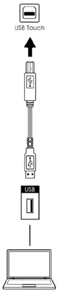
- Connect the USB Cable (USB Type-A connector) to the display.
- Connect the other end of USB cable (USB Type-A) to the USB port on the laptop/PC. See picture below.
- Then turn on the computer.
- When USB cable is fully connected, wait for 5 seconds and the touch function is ready. It can be activated by using the stylus or finger.
Installing an OPS Module
Follow the steps below to install an OPS module.
Step 1. Ensure that the display is turned off
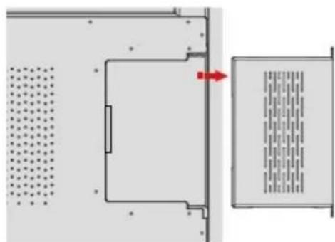
Step 2. Use a screw driver to unscrew the OPS slot shield on the display input panel. Do not lose the screws that are removed.
Step 3. Install the OPS module by sliding it into the OPS slot until you hear a click, indicating the module is securely inserted. When using an Avocor OPS PC, the fan should be visible
Step 4. Secure the OPS module in position by screwing it onto the display input panel using the screws that were removed earlier.
Step 5. Ensure the installation is complete before turning on the power.
Step 6. Turn on the display. When using an Avocor OPS Pc you should see a green light on the side of the OPS, this will indicate that the OPS PC is switched on and operational.
Note. When installing or de-installing an OPS PC, the display must be switched off. If the display is on when performing the installation or deinstallation of the OPS PC, this could cause damage to either the display or OPS PC invalidating the warranty for both.
Step 2
natural_image
Diagram showing a room with a door, vent, and ventilation grilles (no text or symbols)Step 3
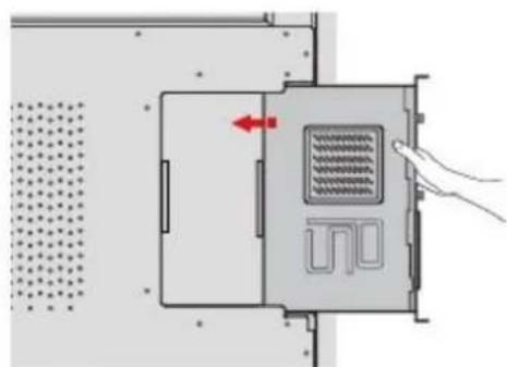
natural_image
Diagram of a device interior with a hand pressing a button, showing no text or symbols.Step 4
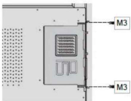
Step 5
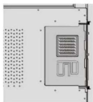
natural_image
Pure electrical circuit lines without any symbolsWarranty Support
Should you require assistance with any suspected hardware fault, please contact the Warranty Support team. Please provide as much information to the support team about the fault and any steps you have taken in trying to try and resolve the fault.
Remember the first instance to look for known faults and how to resolve them on the avocor Website www.avocor.com/support
| Organisation Name | |
| Contact Person | |
| 1st Contact Number (Landline) | |
| 2nd Contact Number (Mobile/Cell) | |
| - | |
| Address(of on-site repair or unit exchange) | |
| City | |
| State | |
| Postcode/ZIP | |
| County/State | |
| Days and hours of operation | |
| Loading & Parking Available? (Yes or No) |
| Reseller Information (If Known) | |
| Organisation Name | |
| Contact Person | |
| Contact Number (Landline) | |
| Product Information | |
| Product / Model | |
| Serial Number | |
| Date of Purchase (If Known) | |
avocor™
UK Warranty Support
UK & EMEA. Tel +44 (0) 1276 804 654 - service@avocor.co.uk
avocor™
- AVE Series
- Quick Start Guide
- E Series Quick Start Guide Table of Contents
- Contents of Packaging
- Accessory Carton
- The Display at a Glance
- Front Buttons
- E-Series Display Inputs
- Front Ports
- Remote Control
- Switching the Avocor display on and off
- Switching on
- Switching off
- Selecting the Source
- Connecting the Display
- Connecting to an external PC using a HDMI connection
- Connecting to an external PC using a DisplayPort connection
- Enabling the Touch Screen
- Connecting the Display to a Host Computer
- Installing an OPS Module
- Warranty Support
- avocor™
Brand : Avocor
Model : E6510
Category : Screen