
CW6GGBTX - Oven Campomatic - Free user manual and instructions
Find the device manual for free CW6GGBTX Campomatic in PDF.


| Product Type | Built-in Electric Oven |
| Brand | Campomatic |
| Model | CW6GGBTX |
| Dimensions (H x W x D) | 59.5 x 59.5 x 56.8 cm |
| Weight | 35 kg |
| Power Supply | 220-240 V ~ 50/60 Hz |
| Maximum Power Consumption | 2900 W |
| Energy Efficiency Class | A |
| Oven Capacity | 70 L |
| Main Functions | Convection, Grill, Defrost, Bottom Heat, Top Heat, Fan Forced |
| Temperature Range | 50°C - 250°C |
| Cleaning Type | Easy-clean enamel interior |
| Safety Features | Child lock, Automatic shut-off, Cool-touch door |
| Control Type | Rotary knobs and digital timer |
| Display | LED digital display |
| Door Type | Drop-down with double glazing |
| Number of Oven Racks | 2 + 1 grill pan |
| Lighting | Interior oven light |
| Spare Parts Availability | Spare parts available for 10 years from manufacturer |
| Repairability Index | 8.5/10 |
| Included Accessories | Oven rack, baking tray, grill pan, handle |
| Installation Type | Built-in under counter or in column |
Frequently Asked Questions - CW6GGBTX Campomatic
User questions about CW6GGBTX Campomatic
0 question about this device. Answer the ones you know or ask your own.
Ask a new question about this device
Download the instructions for your Oven in PDF format for free! Find your manual CW6GGBTX - Campomatic and take your electronic device back in hand. On this page are published all the documents necessary for the use of your device. CW6GGBTX by Campomatic.
USER MANUAL CW6GGBTX Campomatic
natural_image
Simple line drawing of a kitchen oven with three circular control knobs and a blank front panel (no text or symbols)INSTRUCTION MANUAL
Gas oven
Thank you for choosing our product.
We advise you to read this manual carefully. It contains all necessary instructions for maintaining unaltered the appearance and functional qualities of the appliance.
Table of Contents
- PRECAUTIONS FOR USE
- DISPOSAL INSTRUCTIONS-OUR ENVIRONMENT POLICY
- SAFETY PRECAUTIONS
- INSTALLING THE APPLIANCE
- ADAPTING TO DIFFERENT TYPES OF GAS
- DESCRIPTION OF FRONT PANEL CONTROLS
- USING THE OVEN
- CLEANING AND MAINTENANCE
- EXTRAORDINARY MAINTENANCE
- TECHNICAL SPECIFICATIONS
Precautions for Use
1. PRECAUTIONS FOR USE
THIS MANUAL IS AN INTEGRAL PART OF THE APPLIANCE. TAKE GOOD CARE OF IT AND KEEP IT TO HAND THROUGHOUT THE OVEN'S LIFE CYCLE.
WE URGE YOU TO READ THIS MANUAL AND ALL THE INFORMATION IT CONTAINS CAREFULLY BEFORE USING THE APPLIANCE. ALSO KEEP THE SET OF NOZZLES PROVIDED IN A SAFEPLACE. INSTALLATION MUST BE CARRIED OUT BY QUALIFIED STAFF IN COMPLIANCE WITH THE RELEVANT REGULATIONS. THIS APPLIANCE IS INTENDED FOR HOUSEHOLD USE AND COMPLIES WITH THE EEC DIRECTIVES CURRENTLY IN FORCE. THE APPLIANCE IS BUILT TO PROVIDE THE FOLLOWING FUNCTION: COOKING AND HEATING FOODS; ALL OTHER USES ARE CONSIDERED TO BE IMPROPER.
THE MANUFACTURER DECLINES ALL LIABILITY FOR USES OTHER THAN THOSE STATED ABOVE.
NEVER USE THIS APPLIANCE FOR HEATING ROOMS.
NEVER USE PACKAGING RESIDUES UNATTENDED IN THE HOME. SEPARATE THE VARIOUS PACKAGING MATERIALS BY TYPE AND CONSIGN TO THE NEAREST SEPARATE DISPOSAL CENTRE.
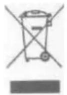
Meaning of crossed -out wheeled dustbin:
Do not dispose of electrical appliances as unsorted municipal waste, use separate collection facilities.
Contact you local government for information regarding the collection systems available.
If electrical appliances are disposed of in landfills or dumps, bhazardous substances can leak into the groundwater and get into the food chain, damaging your health and well-being.
When replacing old appliances with new ones, the retailer is legally obligated to take back your old appliance for disposals at least free of charge.
NEVER OBSTRUCT THE OPENINGS AND SLITS PROVIDED FOR VENTILATION AND HEAT DISPERSAL.
THE NAMEPLATE MUST NEVER BE REMOVED.
NEVER USE METAL SCOURING PADS OR SHARP SCRAPERS; THEY WILL DAMAGE SURFACES.
USE ORDINARY NON-ABRASIVE PRODUCTS WITH THE AID OF WOODEN OR PLASTIC UTENSILS IF NECESSARY. RINSE THOROUGHLY AND DRY WITH A SOFT CLOTH OR CHAMOIS LEATHER.
DO NOT ALLOW SPILLS OF FOODS WITH HIGH SUGAR CONTENT (E.G.JAM) TO DRY INSIDE THE OVEN. IF THEY DRY FOR TOO LONG, THEY MIGHT DAMAGE THE ENAMEL COATING INSIDE OF THE OVEN.
The manufacturer declines all responsibility for injury or damage caused by failure to comply with the above regulations or deriving from tampering with even just one part of the appliance and the use of non-original spare parts.
The environment - Disposal instructions
2. DISPOSAL INSTRUCTIONS - OUR ENVIRONMENT POLICY
Our products are only packaged using non-pollutant, environment-friendly, recyclable materials. We urge you to cooperate by disposing of the packaging properly. Contact your local dealer or the competent local organizations for the addresses of collection, recycling and disposal facilities.
Never leave all or part of the packaging lying around. Packaging parts, and especially plastic bags, may represent a suffocation hazard for children.
Your old appliance must also be disposed of properly.
Important: deliver the appliance to your local organization authorized to collect scrapped appliances.
Proper disposal allows the intelligent recovery of valuable materials.
Before scrapping your appliance it is important to remove doors and leave shelves in position as for use, to ensure that children cannot accidentally become trapped inside the oven during play. Also, cut the power supply lead and remove it and the plug.
Safety Precautions
□3. SAFETY PRECAUTIONS
SEE INSTALLATION INSTRUCTIONS FOR SAFETY REGULATIONS FOR ELECTRIC OR GAS APPLIANCES AND FOR VENTILATION FUNCTIONS.
IN YOUR INTEREST AND TO ENSURE YOUR SAFETY, BY LAW ALL ELECTRIC APPLIANCES MUST ONLY BE INSTALLED AND SERVICED BY QUALIFIED STAFF, IN ACCORDANCE WITH THE RELEVANT REGULATIONS.
OUR APPROVED INSTALLATION ENGINEERS GUARANTEE YOU A JOB WELL DONE.
GAS OR ELECTRIC APPLIANCES MUST ALWAYS BE DISCONNECTED BY SUITABLY SKILLED PEOPLE. THE PLUG TO BE CONNECTED TO THE POWER SUPPLY LEAD AND THE RELATIVE SOCKET MUST BE OF THE SAME TYPE AND COMPLY WITH THE RELEVANT REGULATIONS.
THE POWER SUPPLY SOCKET MUST BE ACCESSIBLE EVEN AFTER THE APPLIANCE HAS BEEN BUILT-IN.
IMMEDIATELY AFTER INSTALLATION, CARRY OUT A QUICK TEST ON THE APPLIANCE FOLLOWING THE INSTRUCTIONS PROVIDED LATER IN THIS MANUAL. IF THE APPLIANCE FAILS TO OPERATE, DISCONNECT IT FROM THE ELECTRICAL MAINS AND CONTACT YOUR NEAREST SERVICE CENTRE. NEVER ATTEMPT TO REPAIR THE APPLIANCE.
NEVER PLACE FLAMMABLE OBJECTS IN THE OVEN: IF IT SHOULD ACCIDENTALLY BE SWITCHED ON, THIS MIGHT CAUSE A FIRE.
THE APPLIANCE BECOMES VERY HOT DURING USE. TAKE CARE NEVER TO TOUCH THE HEATING ELEMENTS INSIDE THE OVEN.
THE APPLIANCE IS INTENDED FOR USE BY ADULTS. KEEP CHILDREN AT A SAFE DISTANCE AND NEVER ALLOW THEM TO PLAY WITH IT.
WHEN THE GRILL IS IN OPERATION, ACCESSIBLE PARTS MAY BECOME VERY HOT: KEEP CHILDREN AT A SAFE DISTANCE.
BEFORE THE APPLIANCE IS PUT INTO OPERATION, ALL THE LABELS AND PROTECTIVE FILMS APPLIED INSIDE OR OUTSIDE MUST BE REMOVED.
AFTER EACH USE, ALWAYS CHECK THAT THE CONTROL KNOBS ARE TURNED TO 0(OFF).
The manufacturer declines all responsibility for injury or damage caused by failure to comply with the above regulations or deriving from tampering with even just one part of the appliance and the use of non-original spare parts.
Instructions for the Installer
4. INSTALLING THE APPLIANCE
Installation must be carried out by a qualified engineer in compliance with the relevant regulations.
4.1 Electrical connection
The nameplate must never be removed.
The appliance must be connected to earth in compliance with electrical system safety regulations.
If a permanent connection is used, the appliance's power supply line must be fitted with an omni polar breaking device with contact gap of at least 3 mm, located in an easily accessible position close to the appliance itself. If a socket and plug connection is used, check that they are of the same type. Do not use reducers, adapters or junctions since they may cause overheating or burns.
Operation at 220-240 V\~: use a type H05RR-F three-wire cable
(Cable of 3 × 1.5 mm^2 ).
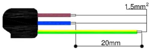
The earth wire (yellow-green) must be at least 20 mm longer than the other wires at the end for connection to the appliance.
The manufacturer declines all responsibility for injury or damage caused by failure to comply with the above regulations or deriving from tampering with even just one part of the appliance.
4.2 Positioning the oven
Only a qualified person in compliance with the instructions provided install the appliance. The manufacturer declines all responsibility for improper installation, which may harm persons and animals and damage property.
Important: - The power supply to the appliance must be cut off before any adjustments or maintenance work is done on it;
- Air duct is supposed to use in Ventilation;
- cabinets with a veneer exterior must be assembled with glues which can withstand temperatures of up to 100^ C.
Installation of Built-in Ovens
In order to ensure that the built-in appliance functions properly, the cabinet containing it must be appropriate.
The appliance is designed for built-in installation (class 3) in cabinets of any heat-resistant material. Comply with the dimensions shown in figures 1, 2 and 3. when installing under worktops, comply with the dimensions shown in figure 1-3. when installing under worktops incorporating hobs, a gap of at least 110 mm must be left from any side wall, as shown in figure 1. when installing in tall units, comply with the dimensions shown in figure 1-2, bearing in mind that the top/rear of the unit must have an opening 45mm deep. Screw the 4 screws A into the inside of the frame (fig.1). For installation under tops, make sure that the rear/bottom of the unit has an opening similar to that shown in figure 1 (B), and that the front/bottom of the unit has an opening an aperture of at least 45×560mm similar to that shown in figure 1-3 (C), or the aperture similar to window shade, make sure that aperture area of at least 45×560mm. see the instructions supplied with the hob for the relative positioning and fixing procedures.
In compliance with current safety standards, contact with the electrical parts of the oven must not be possible once it has been installed.
All parts, which ensure the safe operation of the appliance, must be removable only with the aid of a tool.
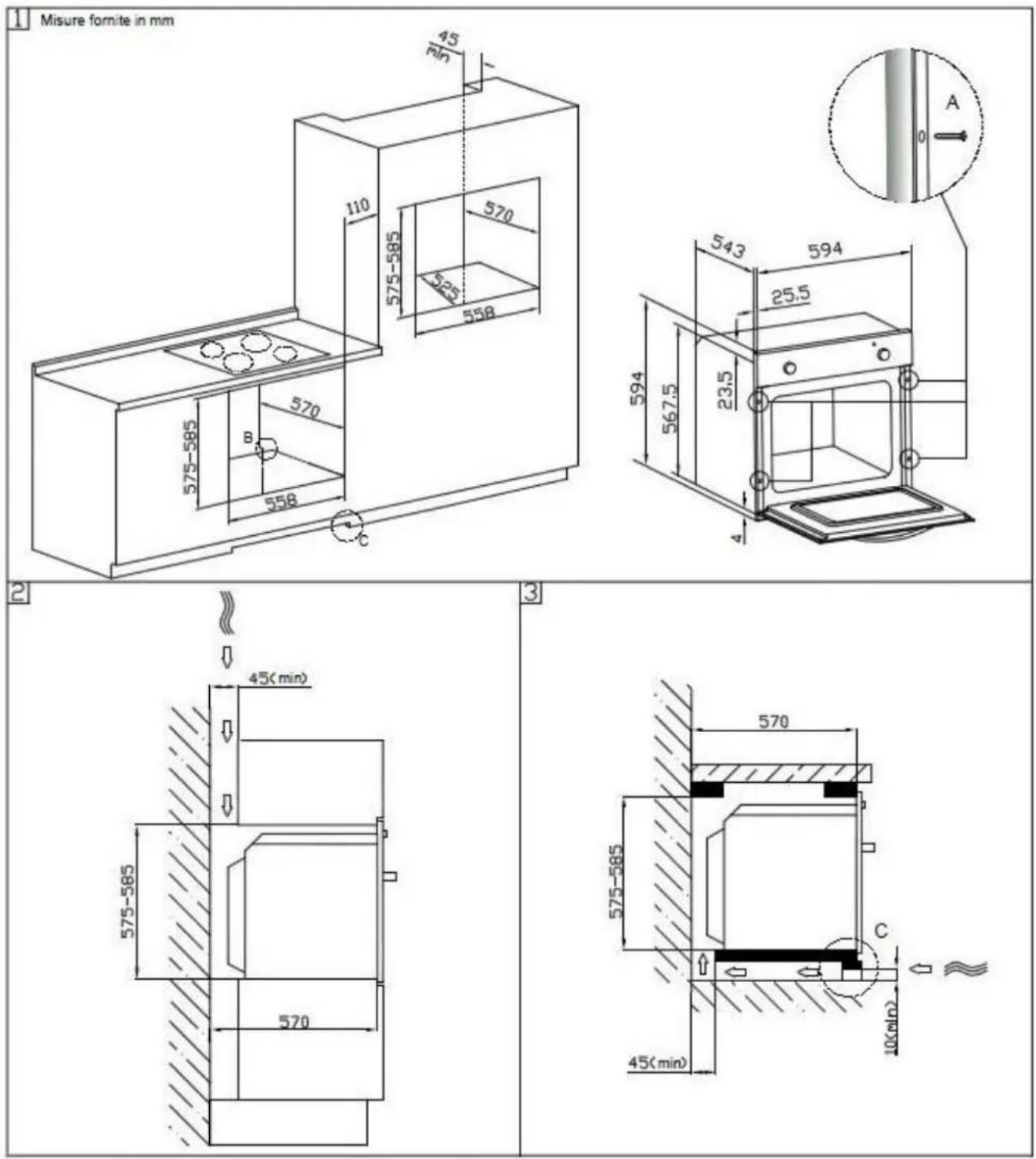
Never use the door for leverage when inserting the oven in the cabinet. Never apply excessive pressure to the open door.
4.3 Room ventilation
The appliance may only be installed in a permanently ventilated room as specified by the relevant regulations. The air flow into the room where the appliance is installed must be sufficient for proper gas combustion and room ventilation. The air intakes, protected by gratings, must be of suitable size (see relevant regulations) and located so that they cannot be even partially obstructed. The kitchen must be kept properly ventilated to disperse the heat and humidity produced by cooking processes: in particular, a window should be opened or the speed of any fans increased after prolonged use.
4.4 Combustion gas discharge
Combustion gases must be discharged by means of hoods connected to a flue with reliable natural draught, or a fan extraction system. An effective extraction system requires careful design by an authorized specialist, and must comply with the regulation distances and positions. After installation, the engineer must issue a certificate
of compliance.
4.5 Gas connection
Connection with copper pipe:
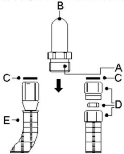
The connection to the gas supply mains must be made so that no stresses or strains of any kind are applied to the appliance. The connection can be made using the adapter unit D with two conical elements, always fitting the gasket C supplied.
Connection with steel hose:
Use only continuous-wall stainless steel hoses compliant with the relevant regulations, and always fit the gasket C supplied between the fitting A and the hose E.
flowchart
graph TD
    A["Component A"] --> B["Process Unit B"]
    B --> C["Component C"]
    C --> D["Component D"]
    D --> E["Component E"]
    style A fill:#f9f,stroke:#333
    style B fill:#ccf,stroke:#333
    style C fill:#cfc,stroke:#333
    style D fill:#fcc,stroke:#333
    style E fill:#cff,stroke:#333
When connecting with a hose, ensure that the total length of the pipeline is not more than 2 meters; also Ensure that the hoses do not touch moving parts and are not crushed
5. ADAPTING TO DIFFERENT TYPES OF GAS
Before carrying out the operations described below, disconnect the appliance from the electricity supply.
The appliance is tested with G20 (2H) natural gas at the pressure of 20 mbar. If it is to be used with other types of gas, the burner nozzle has to be changed and the gas valve adjusted. To replace the nozzle, proceed as described below.
5.1 Adjusting the oven burner
To adjust the oven burner, open the oven door and proceed as follows:
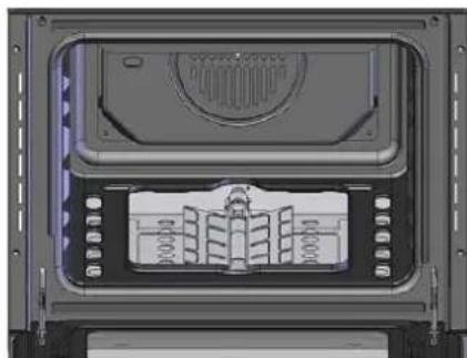
- Remove all accessories (pans, shelves and any steel runners):
- Lift the oven bottom plate and extract it so that the inside of the oven is as shown in the picture.
5.1.1 Adjusting the minimum setting
The oven thermostat has a screw for regulating the minimum setting, accessed by removing the thermostat knob. When the type of gas used changes, the minimum setting must be adjusted as follows:
● Light the oven burner and keep it operating at the highest setting for 10/15 minutes with the door closed.
natural_image
3D rendering of a mechanical or electronic component with internal structure and mounting holes (no visible text or symbols)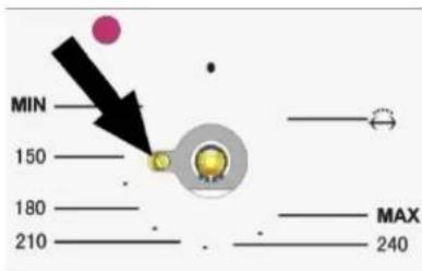
Then turn the knob to the minimum temperature setting, remove the knob and use a straight-head screwdriver to adjust. Firstly, turn the knob in clockwise direction tightly then anticlockwise to adjust the flame. For
natural gas you should turn one of a circle while 1/8 circle for LPG.
- When using bottled gas, the adjuster screw must be turned fully clockwise. The diameter of the by-pass is stated in point "5.2 Burner and Nozzle Data Tables".
- When using town or natural gas, adjust the screw so that when the thermostat knob is turned from the maximum to the minimum setting, the flame always remains stable and uniform. Close the oven door and check that the burner remains on at the minimum setting.
5.1.2 Changing the nozzle
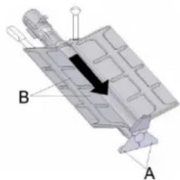
- Undo the oven burner fixing screws A.
- Move the burner B outwards until the nozzle is accessible.
- Use a 7 socket wrench to change the nozzle, fitting the one for the type of gas to be used (see point“5.2 Burner and Nozzle Data Tables”).
natural_image
3D mechanical component diagram with labeled parts A and B, showing internal structure without any text or symbols.5.1.3 Adjusting the oven burner primary air flow
- Undo the adjuster screw“A” of the air regulator sleeve;
- Turn the regulator sleeve" B "into the position for the
type of gas to be used, consulting the table below;
● Tighten the adjuster screw and restore the seals; - When the operation is complete, reassemble the burner correctly.
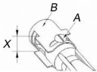
NATURAL GAS (N)
G30/G31 (LPG)
X= 4mm
10mm
When the operation is complete, replace the nameplate on the back of the oven with the one provided for the new type of gas.
In compliance with current safety standards, adapting to different types of gas must be has gas lore of professional can but operation.
5.2 Burner and Nozzle Data Table
| GAS CATEGORY: | I3+(28-30/37) | I3B/P(30) | I3B/P(37) | I3B/P(50) | ||
| TYPES OF GAS: | ☐G30 | ☐G31 | ☐G30 | ☐G30 | ☐G30 | |
| GAS PRESSURE (mbar): | 29 | 37 | 29 | 37 | 50 | |
| HEATINPUT(Hs) | Top burner:1.7kW(124g/h)Bottom burner:2.5kW(182g/h) | Top burner:1.7kW(124g/h)Bottomburner:2.5kW(182g/h) | Top burner:1.7kW(124g/h)Bottom burner:2.5kW(182g/h) | Top burner:1.5kW(109g/h)Bottom burner:2.5kW(182g/h) | ||
| INJECTOR SIZE Top :0.65mm | Top :0.65mmBottom :0.77mm | Top :0.65mmBottom :0.71mm | Top :0.50mmBottom :0.65mm | |||
| GAS CATEGORY: | I2H | I2E | I2E+ | I2L | ||
| TYPES OF GAS: | ☐G20 | ☐G20 | ☐G20 | ☐G25 | ☐G25 | |
| GAS PRESSURE (mbar): | 20 mbar | 20 mbar | 20 | 25 | 25 | |
| HEAT:INPUT(Hs) | Topburner:1.5kWBottomburner:2.6kW | Topburner:1.5kWBottomburner:2.6kW | Topburner:1.5kWBottomburner:2.6kW | Topburner:1.5kWBottomburner:2.6kW | ||
| INJECTOR SIZE Top :0.93mm | Top :0.93mmBottom :1.18mm | Top :0.93mmBottom :1.18mm | Top :0.93mmBottom :1.18mm | |||
| VOLTAGE / FREQUENCY: AC220-240V/50-60HzELECTRIC POWER: 1.8kW | ||||||
| I3+(28-30/37) | I3B/P(30) | I3B/P(37) | I3B/P(50) | I2H | I2E | I2E+ | I2L | |
| IIH3B/P | √ | √ | ||||||
| IIH3+ | √ | √ | ||||||
| IIE+3+ | √ | √ |
| Burner | Rated heat capacity (kW) | BOTTLED GAS - G30/G31 28/37 mbar | ||||
| Nozzle diameter 1/100 mm | By-pass 1/100 mm | Reduced heat capacity (W) | Flow-rate g/h G30 | Flow-rate g/h G31 | ||
| Oven | 2.5 | 77 | 41 | 700 | 189 | 186 |
| Burner | Rated heat capacity (kW) | NATURAL GAS - G20 20 mbar | ||||
| Nozzle diameter 1/100mm | Reduced heat capacity (W) | |||||
| Oven | 2.6 | 118 | 700 | |||
6. DESCRIPTION OF FRONT PANEL CONTROLS
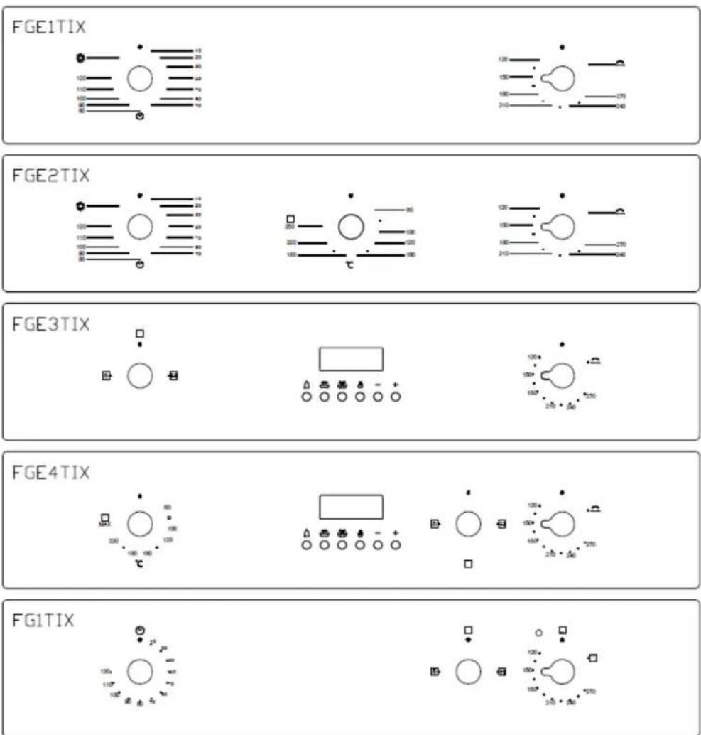
All the cooker's control and monitoring devices are placed together on the front panel. The table below provides the key to the symbols used.
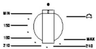
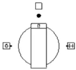
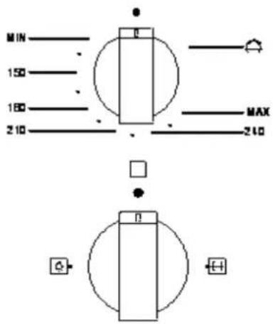
THERMOSTAT KNOB
(ON SOME MODELS ONLY)
This knob lights the gas burner inside the oven. The cooking temperature is set by turning the knob anti-clockwise to the value required, between Min. and Max.
For instructions for lighting the gas oven, refer to point"7.3 Using the Gas Oven".
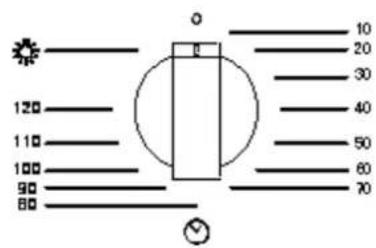
TIMER KNOB
(ON SOME MODELS ONLY)
To use the timer, set the buzzer by turning the knob clockwise. The numbers correspond to minutes (maximum 120 minutes). Setting is on a gradual scale and intermediate positions between the numbers can be used. The end of cooking buzzer does not turn off the oven.
The ⚙️ setting turns on the light inside the oven during normal operation (without timer).
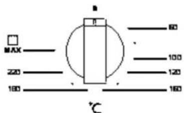
THERMOSTAT KNOB
(ON SOME MODELS ONLY)
The cooking temperature is set by turning the knob clockwise to the value required, between Min. And Max.
FUNCTION SWITCH KNOB
(ON SOME MODELS ONLY)
The ⚙️ setting turns on the light inside the oven during normal
Operation.
The [ ] setting turns on the light and the turnspit inside the oven during normal operation.
6 KEYS ELECTRONIC TIMER
(ON SOME MODELS ONLY)
Digital clock
- Showing time:(0:00-24:00) and minutes.
- The screen shows 3 glittery number and "AUTO" if the power is on.
- In order to set the correct time, press the ⏻ button first, then + or - button to carry forward or backward the figure until the exact time shows.
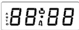
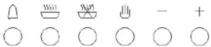
Manual operation setting(only available on the electric grill)
Press the 🏠 button to remove the flashing of "AUTO".
If "auto" is flashing (automatic or semi automatic program has been set), press button to remove "AUTO" and then the manual operation process is on.
Automatic setting (set the time of full automatic starting and ending, only available on the electric grill)
- press 📁 button, set roast time;
- press 📋 button, set roast finish time;
- set temperatures and roast modes by turning the thermostat knob and selector knob.
After the above setting, "AUTO" will be glittering, which means the roast process of the oven is set.
For example: if roast time takes 45 minutes and expect it will end at 14:00.
Press, ____ the roast time is to be 45 minutes;
Press, the roast is set to end at 14:00.
After the above setting, the screen shows the real time(hour、minute)and flashing "AUTO", it means the set roast process is memorized automatically.
When the clock turns to be 13:15(or between 13:14-13:15), the oven will start automatically.
In the roast time, and “AUTO” will be always flashing.
when the clock turns to be 14, the roast has been finished automatically. The alarm will ring and "AUTO" will flash, press the 🔒 button and the ringing will stop.
Semi-automatic setting (set the time of automatic starting and ending, only available on the electric grill)
A. set the time limit of roast (10 hours maximum):
press the 📄 button to set the time of roast;
the oven starts immediately, and "AUTO" will flash. After the roast is finished, the roast operation
process will be shut automatically. Then "AUTO" flashes, the alarm rings. The ringing will stop after the button is pressed.
B. Set the time of ending (23 hours 59 minutes maximum):
press the 🎯 button to set the time of ending;
the oven starts immediately, and "AUTO" will flash. When the set time of ending is reached, the roast process will shut automatically. Then "AUTO" flashes, the alarm rings. The ringing will stop after the button is Pressed.
when the related button is pressed, the set roast process will be displayed. Whenever the 📄 button is pressed, and set backward the time to "0", the set roast process will be cancelled. When 🏠 button is pressed again, the oven will revert to the manual operation process.
Timer
23 hours 59 minutes can be set as maximum.
TO set the time, press the 🔒 button, and then + or - button, until the required time is shown on the screen.
After the setting, the correct time (hour, minute) and the 🔒 button will show on the screen. When the 🔒
button is messed the time displaced will be seen. When the set time is reached, △ disappears and the alarm will ring again. To stop the alarm, press the △ button.
Notice: after pressing the related button, setting is supposed to be done in 5 seconds. In case of blackout, the set process as well as the real time (hour, minute) will disappear. After the power is on again, three "0" and "AUTO" shows on the screen, the oven will automatically reset.
7. USING THE OVEN
7.1 Precautions and General Advice
When the oven and grill are used for the first time, they should be heated to the maximum temperature for long enough to burn off any oily residues left by the manufacturing process, which might contaminatefoods with unpleasant smells.
To avoid unpleasant contact with any steam inside the oven, open the door in two stages: hold it open just a little (about 5 cm) for 4-5 seconds, then open it completely. If you have to check or carry out other procedures on food during cooking, leave the door open for a short time to prevent a drop in the oven temperature which will impair the cooking results.
7.2 Cooling fan system (on some models only)
The appliance is equipped with a cooling system which comes into operation a few minutes after the oven is lit. Operation of the fan generates a normal air flow which comes out above the door and may continue for a short time even after the oven is turned off.
7.3 Using the gas oven
7.3.1 Electronic spark ignition
Completely open the oven door and press the thermostat knob while turning it anti-clockwise to the maximum temperature setting; this automatically activates the electric spark ignition device. Once the burner has ignited, keep the knob pressed down for a few seconds to allow the thermocouple to heat up.
If the burner has not lit after 15 seconds, stop trying, leave the oven door open and wait 1 minute before trying again.
7.3.2 Lighting the burner by hand
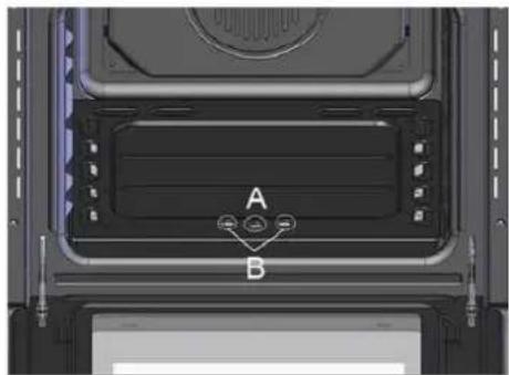
Completely open the oven door and turn the thermostat knob
Anti-clockwise. Place a lit match close to the end of the flame pipe A in the centre of the bottom of the oven and press the thermostat knob. Once the burner has ignited, keep the knob pressed down for a few seconds to allow the thermocouple to heat up and check that the burner has lit properly through the inspection hole B. The cooking temperature is set by turning the knob clockwise to the value required, between 50° and 231°.
If the burner accidentally goes out, turn the knob to the off ( ● ) position and wait at least one minute before trying to relight it.
natural_image
Interior view of a device casing with labeled components A and B, showing internal structure and mounting points (no readable text or symbols beyond labels)7.4 Using the grill
- To turn on the electric grill function, simply turn the gas oven thermostat knob to the 🔔 position.
- To turn on the gas grill function, turn the gas oven thermostat knob to the □ position.
WARNING: THE GAS OVEN AND THE GRILL/ ROTISSERIE CANNOT BE USED SIMULTANEOUSLY.
7.4.1 Operation of the grill + rotisserie
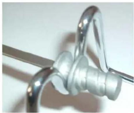
Fit the spit rod into the rotisserie bushing and select grill function (In gas grill model, you must turn FUNCTION KNOB to The

position).
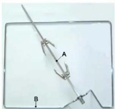
7.4.2 Using the rotisserie in cookers with normal oven
Place the rotisserie shelf "B" on the second pair of runners
from the bottom and fit the rod "A" into the hole in the back of the oven.
natural_image
Close-up of a metallic chain spring with coiled spring, no text or symbols visible7.5 Attention
- Grilling processes must never last more than 60 minutes.
- In enameled models, grill and grill + rotisserie cooking operations must be carried out with the door ajar on the first catch and the knob guard supplied fitted into the top of the oven cavity.
- Accessible parts may be very hot during and after use of the grill; keep children well away from the appliance.
- During rotisserie cooking operations, one of the pans supplied with the cooker should be placed in the bottom of the oven, on the bottom runners, to collect any grease and fat produced.
- When using the oven, remove all unused pans and shelves from its interior.
- During cooking, do not cover the bottom of the oven with aluminum or tin foil, and do not place pans or trays on it; this may damage the enamel coating. If you wish to use greaseproof paper, position it so that it does not interfere with the hot air circulation inside the oven.
8.CLEANING AND MAINTENANCE
Before carrying out any operations, disconnect the appliance from the electricity supply.
Never use a jet of steam for cleaning the inside of the oven.
8.1 Cleaning stainless steel
To keep stainless steel in good condition, it must be cleaned regularly, after each time the cooker is used, after leaving it to cool down.
8.2 Routine daily cleaning
When cleaning and caring for stainless steel surfaces, always use only specific products which do not contain abrasives or chlorine-based acids.
Instructions for use: pour the product onto a damp cloth and wipe over the surface, then rinse thoroughly and dry with a soft cloth or chamois leather.
8.3 Food stains or spills
Never use metal scouring pads or sharp scrapers; they will damage surfaces.
Use ordinary non-abrasive products with the aid of wooden or plastic utensils if necessary.
Rinse thoroughly and dry with a soft cloth or chamois leather.
Do not allow spills of foods with high sugar content (e.g. jam) to dry inside the oven. if they dry for too long, they might damage the enamel coating inside of the oven.
8.4 Cleaning the oven
To keep the oven in good condition, it must be cleaned regularly, after allowing it to cool down.
Remove all removable parts.
Clean the oven shelves with hot water and non-abrasive detergents rinse and dry.
8.5 Cleaning the door glazing
The glass in the door should always be kept thoroughly clean. Use absorbent kitchen roll; remove stubborn dirt with a damp sponge and ordinary detergent.
9. EXTRAORDINARY MAINTENANCE
Occasionally, the oven will require minor servicing procedures or the replacement of parts subject to wear and tear, such as gaskets, light bulbs, etc. The specific instructions for each procedure of this kind are provided below.
Before carrying out any operation involving access to live parts, disconnect the appliance from the electricity supply.
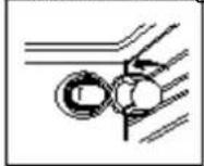
9.1 Replacing the Oven Lamp
- Disconnect the oven from the power supply by means of the omnipolar switch used to connect the appliance to the electrical mains; or unplug the appliance if the plug is accessible;
- Remove the glass cover of the lamp-holder ;
- Remove the lamp and replace with a lamp resistant to high temperatures (300°) with the following
characteristics:
■ Voltage: 220-240V
■ Wattage: 25W
■ Type: E 14
- Replace the glass cover and reconnect the oven to the mains power supply.
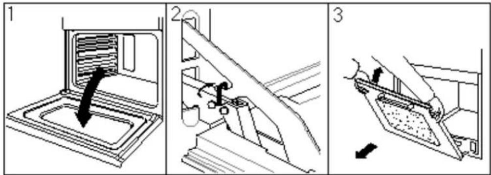
9.2 Removing doors
For a more thorough clean, you can remove the oven door. Proceed as follows:
- Lift up and turn the small levers situated on the two hinges;
· Grip the door on the two external sides, shut it slowly but not
Completely;
· Pull the door towards you, pulling it out of its seat;
Reassemble the door by following the above procedures backwards.
9.3 Removing the gaskets
To allow thorough cleaning of the oven, the door gasket can be removed.
Before removing the gasket, remove the oven door as described above. Once the door has been removed, lift the tangs at the corners as shown in the figure.
10. TECHNICAL SPECIFICATIONS
Inner dimensions of the oven
Width 43.5cm
Depth 40cm
Height 32cm
Inner Volume of the oven 56 litres
Voltage and Frequency of Power Supply:
220-240V \~50/60Hz or 50Hz

1800W
- INSTRUCTION MANUAL
- Gas oven
- Table of Contents
- Precautions for Use
- PRECAUTIONS FOR USE
- THE NAMEPLATE MUST NEVER BE REMOVED.
- The environment - Disposal instructions
- DISPOSAL INSTRUCTIONS - OUR ENVIRONMENT POLICY
- Safety Precautions
- □3. SAFETY PRECAUTIONS
- Instructions for the Installer
- INSTALLING THE APPLIANCE
- Electrical connection
- Positioning the oven
- Installation of Built-in Ovens
- Room ventilation
- Combustion gas discharge
- Gas connection
- Connection with copper pipe:
- Connection with steel hose:
- ADAPTING TO DIFFERENT TYPES OF GAS
- Adjusting the oven burner
- Adjusting the minimum setting
- Changing the nozzle
- Adjusting the oven burner primary air flow
- Burner and Nozzle Data Table
- DESCRIPTION OF FRONT PANEL CONTROLS
- THERMOSTAT KNOB
- (ON SOME MODELS ONLY)
- TIMER KNOB
- FUNCTION SWITCH KNOB
- KEYS ELECTRONIC TIMER
- Digital clock
- Manual operation setting(only available on the electric grill)
- Automatic setting (set the time of full automatic starting and ending, only available on the electric grill)
- Semi-automatic setting (set the time of automatic starting and ending, only available on the electric grill)
- Timer
- USING THE OVEN
- Precautions and General Advice
- Cooling fan system (on some models only)
- Using the gas oven
- Electronic spark ignition
- Lighting the burner by hand
- Using the grill
- WARNING: THE GAS OVEN AND THE GRILL/ ROTISSERIE CANNOT BE USED SIMULTANEOUSLY.
- Operation of the grill + rotisserie
- Using the rotisserie in cookers with normal oven
- Attention
- 8.CLEANING AND MAINTENANCE
- Cleaning stainless steel
- Routine daily cleaning
- Food stains or spills
- Cleaning the oven
- Cleaning the door glazing
- EXTRAORDINARY MAINTENANCE
- Replacing the Oven Lamp
- Removing doors
- Removing the gaskets
- TECHNICAL SPECIFICATIONS
Brand : Campomatic
Model : CW6GGBTX
Category : Oven