
P75 - CD Player CAMBRIDGE - Free user manual and instructions
Find the device manual for free P75 CAMBRIDGE in PDF.


| Product Type | CD Player |
| Brand | Cambridge Audio |
| Model | P75 |
| Disc Loading | Top-loading with hinged lid |
| DAC Type | 24-bit/192kHz |
| Audio Outputs | Analog RCA (pair), Digital Coaxial, Digital Optical |
| Headphone Output | 3.5mm jack with volume control |
| Remote Control | Included (infrared) |
| Playback Functions | Play, Pause, Skip, Repeat (1/All), Random, Program |
| Display | LED display with track/time info |
| Dimensions (W x H x D) | 430 x 80 x 310 mm |
| Weight | 5.0 kg |
| Power Supply | 110-240 VAC, 50/60 Hz |
| Power Consumption | 15 W (standby <1 W) |
| Clean and Care | Clean exterior with dry cloth; use CD lens cleaner for pickup |
| Safety Precautions | Keep away from moisture; do not block ventilation; use only supplied power cord |
| Spare Parts | Remote control, power cord, RCAs available from Cambridge Audio service |
| Reparability | Serviceable by authorized technicians; replaceable laser pickup |
| General Information | Designed in the United Kingdom; supports CD, CD-R/RW |
Frequently Asked Questions - P75 CAMBRIDGE
User questions about P75 CAMBRIDGE
0 question about this device. Answer the ones you know or ask your own.
Ask a new question about this device
Download the instructions for your CD Player in PDF format for free! Find your manual P75 - CAMBRIDGE and take your electronic device back in hand. On this page are published all the documents necessary for the use of your device. P75 by CAMBRIDGE.
USER MANUAL P75 CAMBRIDGE
WARNING: TO PREVENT FIRE OR SHOCK HAZARD, DO NOT EXPOSE THIS APPLIANCE TO RAIN OR MOISTURE. THIS APPLIANCE SHALL NOT BE EXPOSED TO DRIPPING OR SPLASHING WATER AND THAT NO OBJECT FILLED WITH LIQUID SUCH AS VASES SHALL BE PLACED ON APPARATUS..
The lightning flash with arrowhead symbol, within an equilateral triangle, is intended to alert the user to the presence of uninsulated dangerous voltage within the product's enclosure that may be of sufficient magnitude to constitute a risk of electric shock to persons.
The exclamation point within an equilateral triangle is intended to alert the user to the presence of important operating and maintenance (servicing) instructions in the literature accompanying the appliance.
Safety Instructions
- Read These Instructions - All the safety and operating instructions should be read before the appliance is operated.
- Keep These Instructions - The safety and operating instructions should be retained for future reference.
- Heed All Warnings - All warnings on the appliance in the operating instructions should be adhered to.
- Follow All Instructions - All operating and user instructions should be followed.
-
Water and Moisture - Do not use this apparatus near water; for example, near a bathtub, washbowl, kitchen sink, laundry tub, in a wet basement, or near a swimming pool.
-
Cleaning - The apparatus should be cleaned only with a dry cloth.
- Ventilation - Do not block any ventilation openings. Install in accordance with the manufacturer's instructions. Slots and openings in the cabinet are provided for ventilation and to ensure reliable operation of the product and to prevent it from overheating, and these openings must not be blocked or covered. The openings should never be blocked by placing the product on a bed, sofa, rug, or other similar surface. This product should not be placed in a built-in installation, such as a bookcase or rack unless proper ventilation is provided or the manufacturer's instructions have been adhered to.
- Heat - Do not install near any heat sources such as radiators, heat registers, stoves or other apparatus (including amplifiers) that produce heat.
- Grounding or Polarization - Do not defeat the safety purpose of the polarized alternating current line plug or grounding-type plug. A polarized plug has two blades with one wider than the other. This plug will fit into the power outlet only one way. This is a safety feature. A grounding-type plug has two blades and a third grounding prong. The wide blade or the third prong are provided for your safety. If you are unable to insert the provided plug into your outlet, contact your electrician to replace the obsolete outlet.
- Power Cord Protection - Protect the cord from being walked on or pinched particularly at plugs, convenience receptacles, and the point where they exit from the apparatus.
- Attachments - Only use attachments/accessories specified by the manufacturer.
- Carts and Stands - Use only with the cart, stand, tripod, bracket or table specified by the manufacturer, or sold with the apparatus. When a cart is used, use caution when moving the cart/apparatus combination to avoid injury from tip-over.
- Non-Use Periods - Unplug this apparatus during lightning storms or
when unused for long periods of time.
- Servicing - Refer all servicing to qualified service personnel. Servicing is required when the apparatus has been damaged in any way, such as power supply cord or plug is damaged, liquid has been spilled or objects have fallen into the apparatus, the apparatus has been exposed to rain or moisture, does not operate normally, or has been dropped.
- MAINS Plug - The MAINS plug or an appliance coupler is used as the disconnect device, the disconnect device shall remain readily operable.
- Insulation - Class II apparatus with double insulation, and no protective earth provided.

When installing the P75 Amplifier, the clearances shown here MUST be kept for proper ventilation of the amplifier.
Top View

Front View
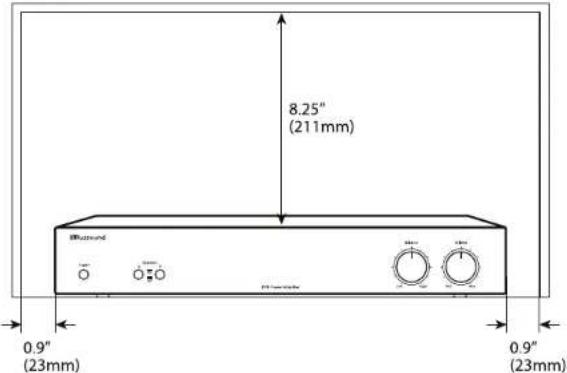
Table of Contents Clearance Requirements
Safety Instructions 2
Product Overview 4
Front and Rear Panels 5
System Configuration - Stereo Mode 6
System Diagram - Stereo Mode....7
System Configuration - Bridged Mode 8
System Configuration - Basic Speaker Connection 9
System Configuration - External Volume Controls 9
Technical Specifications....10
Warranty 11
PRODUCT OVERVIEW
Introduction
The Russound P75 is a 2-channel dual source power amplifier with auto-source switching. It features two audio line inputs with a loop out to another zone, receiver, or device from the Line 2 source.
The P75 amplifier is rated at 75 watts per channel into 4 ohms, and 60 watts into 8 ohms. With the Stereo/Bridge Mono switch in Bridge Mono position, both amplifier channels are combined for a higher powered mono output. In Bridge mode the P75 is rated at 160 watts of power into a single 8 ohm load. Each amplifier output channel incorporates robust protection circuitry for reliability and safety.
Thermal Protection
P75 amplifiers is designed with special circuitry to safeguard the amplifier under a thermal overload condition. Thermal protection mode will only engage when the unit has been run at high volume for extended periods of time without adequate ventilation and/or when speaker impedances are below the minimum levels for the amplifier. In thermal protection mode the amplifier will automatically stop output. If this fault occurs, turn off the amplifier, and check that the speaker impedance rating is above the minimum rating. Also check for adequate ventilation around the amplifier and make adjustments if necessary. Once the unit has cooled to safe operating temperatures, the amplifier may be powered back on.
Protection Circuitry
Special circuitry has been designed into the amplifier to safeguard under a short-circuit condition. A faulty speaker can also cause a short circuit condition. If this fault condition occurs, turn off the amplifier and check speakers for short circuit conditions when appropriate.
Installation
The P75 amplifier can be placed on a shelf in an equipment rack, or on a table or cabinet. Be sure to follow the required clearances shown on page 3 to allow for ventilation and heat dissipation.
Front Panel Controls
On the front panel of the P75 amplifier are the power button plus speaker selector, a master balance and a master volume adjustment.
Power - the front panel switch will manually switch the power on or off.
Power LED indicator - RED = ON, AMBER = Standby, No Light = Protection Mode
Speaker selector - select speaker pair A (main) or speaker pair B (auxiliary) for audio output. You can use speakers A and B together, as long as the speakers are at a minimum 8-ohm impedance.
Balance - adjust speaker output balance between right and left channels. The default setting is at center.
Volume - adjust the speaker output volume. If using Bridged mode, set the volume at minimum, then adjust to the desired level.
Unswitched Outlet
The P75 amplifier has a built-in outlet on the back panel. This 120 VAC outlet provides 400W unswitched power for a device such as a small powered subwoofer. This switch provides power as long as the P75 is plugged into an outlet, whether or not the unit itself is powered on.
Manual / Auto On
The P75 amplifier can be turned on manually or automatically by setting a switch on the back panel. For manual power on or off, press the Power button on the front panel. For automatic power on, set the rear switch to Auto On, and place the front panel power button in the "On" position. When music is sensed on either input RCA connector, the amplifier's signal sensing sends a command for it to power on. Once the signal ends, the amplifier turns off.
Speaker Cable
When connecting speakers to the P75 amplifier, use a minimum 16 gauge and maximum 12 gauge stranded copper cable. Avoid leaving stray strands and keep polarity consistent.


P75 Rear Panel
SYSTEM CONFIGURATION - STEREO MODE WITH DUAL SOURCES
The P75 has dual source capability. If two sources are used, connect the source you want to listen to most of the time to the Line 2 (secondary) input and the source you listen to less constantly to the Line 1 (primary) input.
Whenever the Line 1 (primary) source becomes active, that signal will take priority over the distributed audio signal on the Line 2 (secondary) input. Once the Line 1 (primary) audio signal is muted or turned off, the P75 will automatically switch back to the Line 2 (secondary) audio signal.
Stereo Mode
- Unplug the P75.
- Set the Stereo/Bridge switch to Stereo.
- Connect the audio line output from a stereo preamplifier or source to the left and right Line 2 input jacks of the P75 (for secondary source).
- Connect the audio line output from the primary source to the Line 1 input jacks in the same manner.
- Connect your speakers to the terminals, observing proper polarity.
- Restore power to the amplifier. Use the front panel knobs for Balance and Volume adjustments.

Stereo Mode Configuration with Dual Sources (CD player is primary source)
SYSTEM CONFIGURATION - BRIDGED MODE
Bridge Mode
In this mode both the left and right channels are combined for a higher power mono output.
NOTE: The minimum impedance for the total load connected to a pair of channels in the bridge mode is 8 ohms.
- Unplug the P75.
- Set the Stereo/Bridge switch to Bridge Mono.
- Connect the line out from a preamplifier or source to the Line 2 inputs of the P75.
-
On Speaker A, connect the negative lead (-) of the speaker cable to the L(+) terminal. Connect the positive lead (+) of the speaker cable to the R(+) terminal. (See the Bridge markings on the terminals on the rear panel). An 8 ohm minimum load is required.
-
Restore power to the amplifier.
- On the front panel, set the Balance to center, and set the Volume to Min (minimum). Adjust the output with the volume control to the desired level.
- Set the Balance control on the front panel to Center.

Bridged Mode Connection Detail

Bridged Mode Configuration
SYSTEM CONFIGURATION - EXTERNAL VOLUME CONTROLSYS
System Configuration Using Speaker A and B Connection
The P75 amplifier has a minimum 4 ohm load in stereo mode. Connect up to one pair of 8ohm speakers on A and one pair of 8 ohm speakers on B.
System Configuration with External Volume Controls
The P75 amplifier can be used for multiple pairs of speakers with impedance matching volume controls and/or speaker selectors. In this configuration, connect up to four (total) impedance matching volume controls to the amplifier on speaker A connection only.


flowchart
graph TD
    A["Patio Bedroom"] --> B["8 Ohm Speakers"]
    A --> C["8 Ohm Speakers"]
    B --> D["Autoformer-based Volume Control"]
    C --> E["Autoformer-based Volume Control"]
    D --> F["Speaker Cable"]
    E --> G["Speaker Cable"]
    F --> H["P75 Amplifier"]
    G --> I["EZB-8 Modular Connecting Block"]
    H --> J["Line Out from source"]
    I --> K["Configuration with Autoformer Volume Control"]
TECHNICAL SPECIFICATIONS
P75 Amplifier
Continuous Output Power: 60W per channel at 8 ohms
(<1.0% THD+N) @ 1kHz 75W per channel at 4 ohms
160W bridged mono at 8 ohms
Signal-to-Noise Ratio: 100dB A-weighted
Frequency Response: 10Hz to 30kHz +0.0dB/- 3.0dB @ 8 ohms, 1 W
Input Sensitivity: 900mV for 50W at 8 ohms
Crosstalk: >70dB @ 1 kHz
Power
Requirements: 120VAC 60Hz 4.2A
Dimensions: 16.5"W x 8"D x 2.5"H
(41.9 × 20.3 × 6.4 cm)
Weight: 10.4 lbs. (4.68 kg)
Warranty
The Russound P75 Amplifier is guaranteed against all defects in materials and workmanship for one (1) year from the date of purchase. During this period, Russound will replace any defective parts and correct any defect in workmanship without charge for either parts or labor.
For this warranty to apply, the unit must be installed and used according to its written instructions. If service is necessary, it must be performed by Russound. The unit must be returned to Russound at the owner's expense and with prior written permission. Accidental damage and shipping damage are not considered defects, nor is damage resulting from abuse or from servicing by an agency or person not specifically authorized in writing by Russound.
This Warranty does not cover:
- Damage caused by abuse, accident, misuse, negligence, or improper installation or operation
• Power surges and lightning strikes
• Normal wear and maintenance - Products that have been altered or modified
- Any product whose identifying number, decal, serial number, etc. has been altered, defaced or removed.
Russound sells products only through authorized Dealers and Distributors to ensure that customers obtain proper support and service. Any Russound product purchased from an unauthorized dealer or other source, including retailers, mail order sellers and online sellers will not be honored or serviced under existing Russound warranty policy. Any sale of products by an unauthorized source or other manner not authorized by Russound shall void the warranty on the applicable product.
Damage to or destruction of components due to application of excessive power voids the warranty on those parts. In these cases, repairs will be made on the basis of the retail value of the parts and labor. To return for repairs, the unit must be shipped to Russound at the owner's expense, along with a note explaining the nature of service required. Be sure to pack the unit in a corrugated container with at least three (3) inches of resilient material to protect the unit from damage in transit.
Before returning a unit for repair, call Russound at (603) 659-5170 for a Return Authorization number. Write this number on the shipping label and ship to:
Russound
ATTN: Service
1 Forbes Road
Newmarket, NH 03857
Due to continual efforts to improve product quality as new technology and techniques become available, Russound/FMP, Inc. reserves the right to revise system specifications without notice.
RRussound®
P75 Dual Source Power Amplifier Installation Manual
©2016 Russound. All rights reserved.
All trademarks are the property of their respective owners.
Specifications are subject to change without notice.
Russound, Inc.
1 Forbes Road, Newmarket, NH 03857
tel 603.659.5170 · fax 603.659.5388
email: tech@russound.com www.russound.com
28-1387 11.21.16, Rev.2
Rockustics®
ULTRA-FIDELITY OUTDOOR SPEAKERS

natural_image
Black-and-white photo of a large, textured stone structure with vertical grooves, surrounded by shrubbery (no text or symbols visible)ROCK SPEAKERS | OWNER'S MANUAL
ROCK SPEAKERS | OWNER'S MANUAL
Please read the following instructions carefully before installing your Rockustics ® Rock speaker. If you have any questions regarding installation that are not answered in the following directions, please contact your local sound contractor or the Rockustics ® /MSE Audio ® technical support team. Contact information can be found on the back of the manual.
Basic Wiring
(Diagram A) Locate speaker wire on the underside of the rock. If necessary, strip the wire ends and trim the wire to the appropriate length. Use the supplied silicone wire nut to connect the positive (red) leads of the speaker and input wires. Repeat this step with the negative (black) leads. Rockustics recommends using 14ga or heavier Direct Burial cable for the connection between the amplifier and the speakers.

Diagram A
NOTE: The provided wire nuts are meant for permanent installation use only. If you are temporarily wiring the speakers, do not use these wire nuts. In the event you have used the wire nuts, and need to re-wire your system, do not attempt to unscrew the nuts. Instead, clip the wires below the nut, and follow the steps in the Basic Wiring section with a new pair of waterproof wire nuts (these are available at most hardware stores).
Optimizing Speaker Placement for Best Sound
All Rockustics speakers can generate a high SPL (sound pressure level). Be ready to rock, but be considerate of your neighbors! Maximum acoustic performance should be an important factor in determining speaker placement. Here is how to achieve it:
1) Establish where the most likely or average listening position will be.
2) The speakers should be placed at or close to the same distance from that point.
3) The actual distance between the listening position and the location of the speakers is not critical. However, keep in mind that as the distance between listening area and speaker is increased, there will be a noticeable decrease in perceived volume.
4) Be sure to confirm amp power matches the power rating on the speaker. Over-driving the speaker can lead to permanent damage that is not covered under warranty.
Optimizing Aesthetics with Speaker Placement
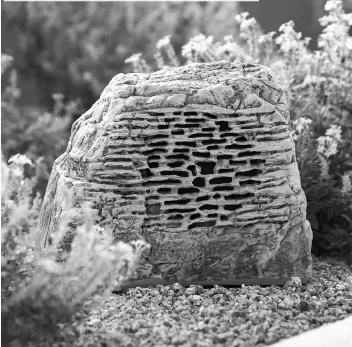
All Rockustics products are designed with a boost in high frequency response to accommodate for placement near plants and other landscaping features. Feel free to position the product within your landscaping, camouflaged near bushes or shrubs. Rockustics products strive to blend into the natural aesthetic of their surroundings.
Be sure to account for the wires which will run from the rock to your stereo or audio source. Camouflage wires by running them an inch below ground level when possible.
Cautions and Maintenance
All Rockustics Rock Series speakers are sealed and fully weatherproof. However, DO NOT place speakers where the grille will be in the path of a sprinkler system. Sprinklers typically have a high water pressure level that can damage speaker cones if hit directly.
DO NOT place soil or wood chips over the speaker grille. If the grilles accumulate a build up of soil, the speaker may become damaged. If build up does occur, simply rinse the grille with a garden hose set to a low pressure level. Accumulated soil may also promote undesired insect traffic into the speaker. Insects may eat through the speaker cone. Chemical sprays may also cause damage to the rubber of the speaker surround. This includes bug spray, deck sealant, some fertilizers and oil based products. Speakers MUST be covered when applying these treatments or chemicals in your yard.
For environments that get snow and ice during the winter months, be sure to check that the openings and woofer cone are clear and there is no hard-packed snow or ice built up in these areas before playing. If there is ice or snow present on the cone, use a hair dryer set on a low setting to to melt it away. If the speakers are not going to be used during winter months, it is recommended that they either be disconnected and brought indoors, or covered with a plastic bag to help protect the speaker components.
Wiring for 70V/100V Applications
For speakers with transformers, use Diagram C to find the proper wire selection for your desired tap setting. Once the desired tap setting is confirmed, trim the unused wires to minimize corrosion. For harsh and wet environments, it is recommended to apply a bead of silicone to the end of the unused wires for added protection.
If daisy-chaining, follow wire preparations as outlined in the Basic Wiring section. Review Diagram E for a typical daisy-chain wiring system for 70V and 100V applications. Be sure to connect the wires going to the next speaker in the chain as shown in Diagram D. There should be three pairs of wires at each speaker, but the last speaker in the chain will only have two pair. Follow standard protocol for polarity and make sure all units are wired with the same polarity.

Diagram C

Diagram D

flowchart
graph TD
    A["SoundTube MA3501t 70V Amplifier"] --> B["Flexible"]
    B --> C["Subwoofer can be connected anywhere in the daisy chain."]
    style A fill:#f9f,stroke:#333
    style B fill:#ccf,stroke:#333
    style C fill:#cfc,stroke:#333
Diagram E
Applicable Models
PunkRock™
PunkRock™ Transformer
EconoRock™
EconoRock™ Transformer
Pavarocci™
Pavarocci™ Transformer
OctoRock™
OctoRock™ Transformer
Rocky Jr. TM
Rocky Jr. TM Transformer
StoneHenge™ II
StoneHenge™ II Transformer
SurroundStone™ 8
SurroundStone™ 8 Transformer
CRUTCHFIELD®
Thank you for purchasing your Russound amplifier from Crutchfield. The manufactures warranty for this amplifier is 2 years, however thanks to our partnership with Russound, this has been extended by Russound to 3 years from the original date of purchase. During this timeframe Crutchfield will, at Crutchfield's sole discretion, exchange the amplifier if it is found to be defective. If the amplifier is no longer available, a replacement model of similar features as solely determined by Crutchfield will be substituted.
The cost for the packaging, insurance and return shipping to Crutchfield of the defective amplifier is the responsibility of the purchaser, and the cost of packaging and shipping of the replacement amplifier will be the responsibility of Crutchfield.
Any and all other terms and conditions of the Amplifier's original Russound owner's warranty remain in full force, except as modified by this document.
Please contact Crutchfield Customer Service at 1-800-955-9091 if you are experiencing any issues with your Russound amplifier and our agents will help diagnose the problem and if the product is found to be defective within the normal stipulations of the manufactures warranty, a repair or replacement will be arranged for a period of 3 years from the original date of purchase.



- Safety Instructions
- Table of Contents Clearance Requirements
- PRODUCT OVERVIEW
- Introduction
- Thermal Protection
- Protection Circuitry
- Installation
- Front Panel Controls
- Unswitched Outlet
- Manual / Auto On
- Speaker Cable
- SYSTEM CONFIGURATION - STEREO MODE WITH DUAL SOURCES
- Stereo Mode
- SYSTEM CONFIGURATION - BRIDGED MODE
- Bridge Mode
- SYSTEM CONFIGURATION - EXTERNAL VOLUME CONTROLSYS
- System Configuration Using Speaker A and B Connection
- System Configuration with External Volume Controls
- TECHNICAL SPECIFICATIONS
- P75 Amplifier
- Warranty
- Russound
- RRussound®
- P75 Dual Source Power Amplifier Installation Manual
- Rockustics®
- ROCK SPEAKERS | OWNER'S MANUAL
- Basic Wiring
- Optimizing Speaker Placement for Best Sound
- Optimizing Aesthetics with Speaker Placement
- Cautions and Maintenance
- Wiring for 70V/100V Applications
- Applicable Models
- CRUTCHFIELD®
Brand : CAMBRIDGE
Model : P75
Category : CD Player