
KS 100 G - Oven KENWOOD - Free user manual and instructions
Find the device manual for free KS 100 G KENWOOD in PDF.


| Type | Built-in Electric Oven |
| Brand | Kenwood |
| Model | KS 100 G |
| Height | 59.5 cm |
| Width | 59.5 cm |
| Depth | 55 cm |
| Net Weight | 32 kg |
| Power Supply | 220-240 V, 50/60 Hz |
| Power Consumption | 2.5 kW (max) |
| Oven Capacity | 65 L |
| Cooking Functions | Conventional, Fan, Grill, Fan-Assisted Grill, Defrost |
| Temperature Range | 50°C - 250°C |
| Control Type | Mechanical Knobs and Timer |
| Interior Light | Yes |
| Cleaning | Standard Enamel Interior, Manual Cleaning Recommended |
| Door Type | Drop-Down with Glass Window |
| Safety Features | Child Lock, Automatic Shut-Off, Overheat Protection |
| Spare Parts Availability | Genuine Kenwood Parts Available |
| Installation Type | Built-in or Freestanding |
| Energy Efficiency Class | A (Estimated) |
Frequently Asked Questions - KS 100 G KENWOOD
User questions about KS 100 G KENWOOD
0 question about this device. Answer the ones you know or ask your own.
Ask a new question about this device
Download the instructions for your Oven in PDF format for free! Find your manual KS 100 G - KENWOOD and take your electronic device back in hand. On this page are published all the documents necessary for the use of your device. KS 100 G by KENWOOD.
USER MANUAL KS 100 G KENWOOD
Instructions for use - Installation advice

natural_image
Front view of a modern kitchen oven with three rotary gauges and a blank chamber (no text or symbols on main components)CE
KENWOOD
Before operating this oven, please read these instructions carefully
CONTENTS Page Number
Introduction 3 - 4
Important Safeguards & Recommendations 5
Control Panel 6
How to use the Fan Oven.... 7 - 14
Minute Counter 15
Cleaning & Maintenance 16 - 22
Advice for the Installer 23
Installation 24 - 27
Gas Section 28 - 35
Electrical installation 36 - 37
Guarantee 38
Dear Customer,
Thank you for having purchased and given your preference to our product. The safety precautions and recommendations within this booklet are for your own safety and that of others. They will also provide a means by which to make full use of the features offered by your appliance.
Please preserve this booklet carefully. It may be useful in future, either to yourself or to others in the event that doubts should arise relating to its operation.
This appliance must be used only for the task it has explicitly been designed for, that is for cooking foodstuffs. Any other form of usage is to be considered as inappropriate and therefore dangerous.
The manufacturer declines all responsibility in the event of damage caused by improper, incorrect or illogical use of the appliance.
Declaration of CE Conformity
This oven has been designed to be used only for cooking.
Any other use (such as heating a room) is improper and dangerous.
This oven has been designed, constructed, and marketed in compliance with:
—safety requirements of EU Directive "Gas" 2009/142/EC;
—safety requirements of EU Directive "Low voltage" 2006/95/EC;
—safety requirements of EU Directive "EMC" 2004/108/EC;
—requirements of EU Directive 93/68/EEC.
Before Using for the First Time
- Read the instructions carefully before installing and using the appliance.
• After unpacking the appliance, check that it is not damaged. In case of doubt, do not use the appliance and contact your supplier or a qualified engineer. - Remove all the packing materials (i.e. plastic bags, polystyrene foam, etc.) and do not leave it around within easy reach of children, as these may cause serious injuries. The packaging materials are recyclable (symbol 🌐)
- The installation and all the gas/electrical connections shall be made by a qualified engineer in compliance with local regulations in force and following the manufacturer's instructions.
- Do not attempt to modify the technical characteristics of the appliance, as it may be come dangerous to use.
Using the Oven for the First Time
You are advised to carry out the following operations:
- Assemble the interior of the oven as described under the heading “Cleaning and maintenance”.
- Switch the empty oven ON at maximum temperature for about two hours to eliminate traces of grease and smell from the components.
- Let the oven cool down, switch off the electrical supply, then clean the inside of the oven with a cloth soaked in water and neutral detergent and dry thoroughly.
Important Precautions and Recommendations for Use of Electrical Appliances
Use of any electrical appliance implies the necessity to follow a series of fundamental rules. In particular:
• never touch the appliance with wet hands or feet;
• do not operate the appliance barefooted;
• do not allow children or disabled people to use the appliance without your supervision.
The manufacturer cannot be held responsible for any damages caused by improper, incorrect or unreasonable use of the appliance.
Important Safeguards & Recommendations
- If you should decide not to use this appliance any longer (or decide to substitute an older model), before disposing of it, it is recommended that it is made inoperative in an appropriate manner in accordance to health and environmental protection regulations, ensuring in particular that all potentially hazardous parts be made harmless, especially in relation to children who could play with unused appliances.
• Some appliances are supplied with a protective film on steel and aluminium parts.
This film must be removed before using the appliance.
- Do not carry out any cleaning or maintenance without first disconnecting the appliance from the electrical supply.
- During and after use of the oven, certain parts will become very hot. Do not touch hot parts.
• After use always ensure that the control knobs are in the "O" (OFF) position. - Keep children away from the oven during use.
• Household appliances are not intended to be played with by children. - Children, or persons with a disability which limits their ability to use the appliance, should have a responsible person to instruct them in its use. The instructor should be satisfied that they can use the appliance without danger to themselves or their surroundings.
- WARNING. When correctly installed, your product meets all safety requirements laid down for this type of product category. However special care should be taken around the rear or the underneath of the appliance as these areas are not designed or intended to be touched and may contain sharp or rough edges, that may cause injury.
- Fire Risk! Do not store inflammable materials inside the oven.
- Always use oven gloves when removing the shelves and food trays from the oven whilst hot.
- Clean the oven regularly and do not allow fat or oils to build up in the oven base or trays. Remove spillages as soon as they occur.
- Do not line the oven walls with aluminium foil. Do not place baking trays or the drip tray on the base of the oven chamber.
- Always stand back from the oven when opening the oven door to allow steam and hot air to escape before removing the food.
- Do not hang towels, dishcloths or other items on the oven or its handle – as this could be a fire hazard.
• Make sure that electrical cords connecting other appliances in the proximity cannot become entrapped in the oven door. - Safe food handling: leave food in the oven for as short a time as possible before and after cooking. This is to avoid contamination by organisms which may cause food poisoning. Take particular care during warmer weather.
- Important: This appliance has been designed for domestic use only.
1 - CONTROL PANEL
Fig. 1.1

Controls Description
- Gas oven/gas grill control knob
- 60' timer control knob
- Oven light / fan motor control knob
Notes:
- The electric ignition is incorporated in the thermostat control knob.
- The appliance has a safety valve system fitted, the flow of gas will be stopped if and when the flame should accidentally go out.
CAUTION:
If the burner is accidentally extinguished, turn the gas off at the control knob and wait at least 1 minute before attempting to relight.
CAUTION:
Gas appliances produce heat and humidity in the environment in which they are installed.
Ensure that the cooking area is well ventilated by opening the natural ventilation grilles or by installing an extractor hood connected to an outlet duct.
CAUTION:
If the appliance is used for a prolonged time it may be necessary to provide further ventilation by opening a window or by increasing the suction power of the extractor hood (if fitted).
2 - HOW TO USE THE FAN OVEN
Technical Features
The oven is furnished completely clean.
It is advisable however, upon first use, to turn the oven on to the maximum temperature to eliminate possible traces of grease from the oven burner.
The same operation shall be done with the gas grill.
This oven is fitted with:
- One gas oven burner (2,70 kW), located at the bottom, providing self-ignition and safety device.
- One gas grill burner (2,10 kW), placed on the top, providing self-ignition and safety device.
- A fan motor, positioned on the back panel of the oven cavity, which can be used:
• in combination with the oven gas burner; - alone, without heating.
- in combination with the oven gas burner;
- alone, without heating.
IMPORTANT NOTE - It is not possible to use the fan motor in combination with the gas grill: a safety device switches off the fan motor when the gas oven/grill control knob is turned on grill position.
Operating Principles
Heating and cooking in the gas oven are obtained in the following ways:
a. by Normal Convection
The heat is produced by the oven gas burner.
b. by Forced Convection
The heat produced by the oven burner is distributed throughout the oven by the fan.
c. by Radiation
The heat is radiated by the gas grill.
d. by Ventilation
The food is defrosted by using the fan only without oven burner (this is not a cooking function).
Cooling Fan Motor
This appliance incorporates a safety cooling fan motor to achieve optimum efficiency of the controls, ensure lower surface temperatures are maintained and cool the internal components.
The cooling fan motor turns on automatically when igniting the oven or grill burner.
It may run on (for various minutes) even after the oven or grill burner has been turned off.
The duration of this time is dependent on previous cooking temperature and duration.
ATTENTION:
The oven door becomes very hot during operation and very hot steam goes out from the area below the control panel. Keep children away.
The door is hot, use the handle.
During use the appliance becomes hot.
Care should be taken to avoid touching the heating elements inside the oven.
IMPORTANT NOTES:
- Do not use the appliance in case of power failure or if the cooling fan motor is damaged. The appliance may overheat and get damaged due to the non-operation of the cooling fan motor.
- In case of failure of the cooling fan motor during the operation of the gas oven or grill, the oven or grill burner is turned off automatically after about 20 minutes. In that case do not use the appliance and contact the after-sales service.
- When the cooling fan motor is operating correctly there is an air flow in the top area of the appliance (fig. 2.1).

Oven Burner
The gas flow to the burner is regulated by a thermostat which allows to maintain the oven temperature constant.
The control of the temperature is assured by a thermostatic probe positioned inside the oven. The probe must be always kept in its housing, in a clean condition, as an incorrect position or encrustment may cause an alteration in the control of the temperature.
Moreover, the thermostat is fitted with a safety valve which automatically shuts off the gas supply when the flame goes out.
Thermostat
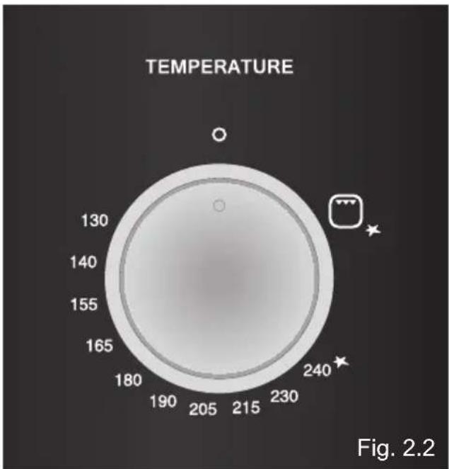
The numbers printed on the control panel (fig. 2.2) indicate the increasing oven temperature value.
To regulate the temperature, set the knob to the chosen number. The ★ symbol close to the maximum position indicates that the electric ignition is incorporated into the knob (activated by the knob itself).
radar
| Temperature | | ----------- | | 130 | | 140 | | 155 | | 165 | | 180 | | 190 | | 205 | | 215 | | 230 | | 240 |Lighting of Oven Burner
IMPORTANT: The oven door must be open during this operation.
To ignite the oven burner:
1 Fully open the oven door.
If this operation is not performed you should not proceed to light the oven.
- Press the thermostat knob throughly to start up the electric ignition and, keeping the
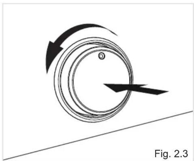
knob under pressure turn it anti-clockwise (fig. 2.3) to the maximum position 240★(fig. 2.2).
Never continue this operation for more than 15 seconds. If the burner has still not ignited, wait for about 1 minute prior to repeating the ignition.
In case of mains failure, to light the oven manually, approach a flame to the hole “A” of the floor (fig. 2.4), then press and turn the thermostat knob (fig. 2.3).
-
Wait about ten seconds after lighting the burner to release the knob (priming time of the thermocouple).
-
Check that the burner has lit; if not, turn the knob clockwise back to "O" (OFF) and repeat the procedure from step 1.
-
Close the oven door slowly and adjust the thermostat knob on the desired setting.
If the flame extinguishes for any reason, the safety valve will automatically shut off the gas supply to the burner.
To re-light the burner, first turn the oven control knob to OFF position O", wait for at least 1 minute and then repeat the lighting procedure.
For the correct use of the gas oven see the chapters "COOKING WITH GAS OVEN" and "COOKING WITH FAN ASSISTED GAS OVEN".
During and after use of the oven, certain parts will become very hot. Keep children away.
ATTENTION: In case of manual lighting, never turn the thermostat before approaching a flame to the hole "A" of the floor.
natural_image
Diagram showing a circular object with an arrow indicating rotational motion, resting on a diagonal line (no text or symbols)
Lighting of Gas Grill Burner
IMPORTANT: The oven door must be open during this operation.
To light the burner, you need to:
1 Fully open the oven door.
If this operation is not performed you should not proceed to light the oven.
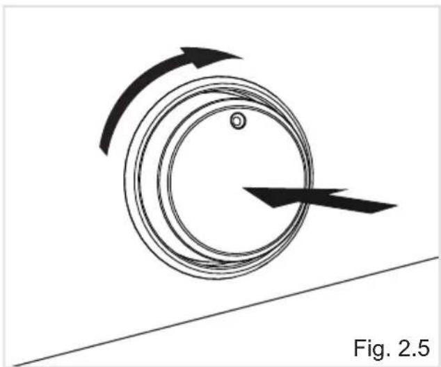
2 Press the thermostat knob throughly to start up the electric ignition and, keeping the knob under pressure turn it clockwise (fig. 2.5) to position ☐ (fig. 2.2).
Never continue this operation for more than 15 seconds. If the burner has still not ignited, wait for about 1 minute prior to repeating the ignition.
In case of mains failure, to light the grill manually, put a flame to the right and left side of the burner (fig. 2.6), then press and turn the thermostat knob (fig. 2.5).
-
Wait about ten seconds after the burner lighting before releasing the knob (priming time of the thermocouple).
-
Check that the burner has lit; if not, turn the knob anti-clockwise back to "O" (OFF) and repeat the procedure from step 1.
-
The oven door must always be kept half-open when the grill is in operation.
For correct use see chapter "TRADITIONAL GRILLING".
If the flame extinguishes for any reason, the safety valve will automatically shut off the gas supply to the burner.
To re-light the burner, first turn the grill control knob to OFF position “O”, wait for at least 1 minute and then repeat the lighting procedure.
IMPORTANT NOTE: It is not possible to use the fan motor in combination with the gas grill; a safety device switches off the fan motor when the gas oven/grill control knob is turned on grill position.
During and after use of the grill, certain parts will become very hot. Keep children away.
ATTENTION: In case of manual lighting, never turn the thermostat before approaching a flame to the burner.
natural_image
Diagram showing a circular object with curved arrows indicating motion, resting on a diagonal line (no text or symbols)
natural_image
Illustration of a hand inserting a component into a rack inside a device (no text or symbols visible)Cooking With Gas Oven
Before introducing the food, preheat the oven to the desired temperature.
For a correct preheating operation, it is advisable to remove the tray from the oven and introduce it together with the food, when the oven has reached the desired temperature.
Check the cooking time and turn off the oven 5 minutes before the theoretical time to recuperate the stored heat.
Fan Motor
The fan motor is designed to distribute throughout the oven the heat generated by the oven gas burner.
The fan motor can also be used without the oven gas burner (without heating) to defrost frozen foods.
The fan is controlled by a knob (fig. 2.7).
-To operate the fan motor turn the knob indicated in fig. 2.7 to position 📊.
- To switch it off turn the knob to the off position "O".
IMPORTANT: When using the fan motor together with the oven gas burner, switch on the fan only after the ignition of the gas burner.

Cooking With Fan Assisted Gas Oven (Oven Burner and Fan Motor - fig. 2.8)
After the ignition of the gas burner, close the oven door and switch on the fan motor.
Before introducing the food, preheat the oven to the desired temperature.
For a correct preheating operation, it is advisable to remove the tray from the oven and introduce it together with the food, when the oven has reached the desired temperature.
Check the cooking time and turn off the oven 5 minutes before the theoretical time to recuperate the stored heat.
Defrosting Frozen Foods (Fan Motor Only - fig. 2.9)
Switch on the fan motor only.
The oven thermostat control knob shall be in the "O" (off) position.
The defrosting is done by simple ventilation without heat.

natural_image
Diagram of a server rack with internal components and directional arrows indicating flow or movement (no text or symbols)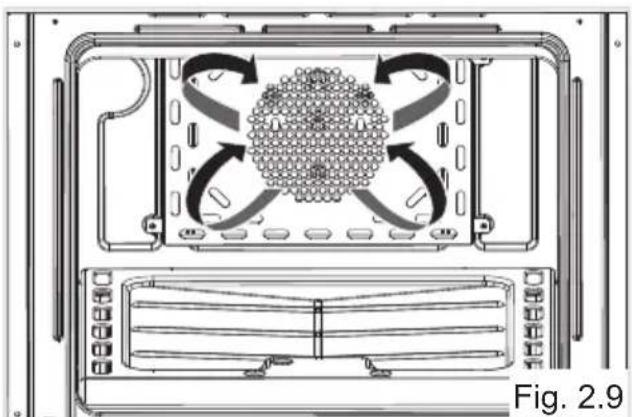
natural_image
Technical diagram of a server rack with internal fan and ventilation system (no text or symbols)Oven Light
The oven provides an interior lamp to allow the visual inspection during the cooking. To light the oven lamp turn the knob indicated in fig. 2.7 to position ☐.
Traditional Grilling
Warning: The grill burner must be used with the door ajar only.
Leave to warm up for approximately 5 minutes with the door ajar. Place the food inside positioning the rack as near as possible to the grill. Insert the drip pan under the rack to collect the cooking juices.
The operation of the grill should not exceed 30 minutes.
Attention: The oven door becomes very hot during operation. Keep children away.

natural_image
Diagram of a door handle with curved arrows indicating flow or movement, no text or symbols present
Fig. 2.10
WARNING !!
The grill burner must be used with the door ajar only.
The cooling fan air flow (below the control panel) allows a correct discharging of the hot air coming from the inside of the cavity. Do not use the grill burner if the cooling fan is not operating (e.g. mains failure, cooling fan broken).
Cooking Guide
Your gas oven is a newly designed oven which incorporates an indirect burner located under the oven base plate.
If you have previously been used to cooking with gas you may need to slightly alter your cooking methods.
The bottom of the oven is hot and is ideal for browning the underside of shallow pastry dishes and pizzas.
Other items should be cooked nearer the top of the oven.
When baking cakes, scones etc on more than one shelf the best results will be achieved by swapping the shelf positions over half way through the cooking process.
Safety
NEVER allow fat to build on the oven base.
As with all ovens, clean and empty fat regularly from the trays and oven base to avoid the possibility of fat fires.
The oven incorporates a safety cooling fan motor to achieve optimum efficiency of the controls, ensure lower surface temperatures are maintained and cool the internal components.
However, the oven door can become hot - keep children away from this appliance.
NEVER place anything on the bottom of the oven.
Do not line the oven walls with aluminium foil.
Do not place baking trays or the drip tray on the base of the oven chamber.
| Temperature recipe guide | |||
| MARK | APPROX. TEMP. | HEAT OF OVEN | TYPE OF DISH TO COOK |
| 130 | 130°C266°F | Very cool oven | Meringue cakes, slow cooking items. |
| 140 | 140°C - 145°C284°F - 293°F | Cool oven | Milk puddings, very rich fruit cakes, i.e., Christmas. |
| 155 | 155°C311°F | Cool or slow oven | Stews, casseroles, braising, rich fruit cakes, i.e., Dundee. |
| 165 | 165°C - 170°C329°F - 338°F | Cool or slow oven | Biscuits, rich plain cakes i.e., Madeira.Low temp. roasting. |
| 180 | 180°C350°F | Warm oven | Plain cakes, Victoria sandwich, raised meat pies. |
| 190 | 190°C - 195°C374°F - 383°F | Moderate oven Small cakes, savoury flans, fish. | |
| 205 | 205°C401°F | Fairly hot oven | Plain cakes and buns, swiss rolls, fruit pies. High temp. roasting. |
| 215 | 215°C - 220°C419°F - 428°F | Hot oven | Bread and bread rolls etc., scones, flaky and rough puff pastry, yorkshire pudding. |
| 230 | 230°C446°F | Moderately hot oven | Sausage rolls, mince pies, puff pastry, pizza. |
| 240 | 240°C464°F | Very hot oven Browning ready cooked dishes. | |
3 - MINUTE COUNTER
60' Timer
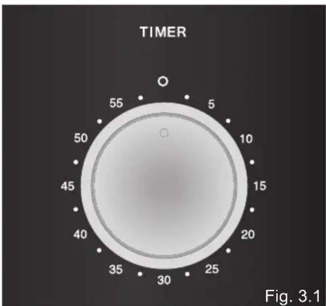
The minute counter is a timed acoustic warning device which can be set for a maximum of 60 minutes.
The knob (Fig. 3.1) must be rotated clockwise as far as the 60 minute position and then set to the required time by rotating it anticlockwise.
IMPORTANT WARNING:
This is only a mechanical timer.
Remember to turn off the oven/grill manually.
4 - CLEANING AND MAINTENANCE
Care and Maintenance
IMPORTANT: Before any operation of cleaning and maintenance disconnect the appliance from the electrical supply.
CAUTION: Do not use a steam cleaner because the moisture can get into the appliance thus make it unsafe.
It is advisable to clean when the appliance is cold and especially for cleaning the enamelled parts.
Do not use abrasive substances or nonneutral detergents as these will irreparably damage the surface.
Avoid leaving alkaline or acidic substances (lemon juice, vinegar, etc.) on the surfaces.
Avoid using cleaning products with a chlorine or acidic base.
WARNING
When correctly installed, your product meets all safety requirements laid down for this type of product category. However special care should be taken around the rear or the underneath of the appliance as these areas are not designed or intended to be touched and may contain sharp or rough edges, that may cause injury.
Inside of Oven
The oven should always be cleaned after use when it has cooled down.
The cavity should be cleaned using a mild detergent solution and warm water.
Suitable proprietary chemical cleaners may be used after first consulting with the manufacturers recommendations and testing a small sample of the oven cavity. Abrasive cleaning agents or scouring pads/cloths should not be used on the cavity surface.
NOTE: The manufacturers of this appliance will accept no responsibility for damage caused by chemical or abrasive cleaning.
ATTENTION: Let the oven cool down and pay special attention no to touch the hot heating elements inside the oven cavity.
CAUTION: Do not store flammable material in the oven.
Enamelled Parts
All the enamelled parts must be cleaned with a sponge and soapy water only or other non-abrasive products.
Dry preferably with a micro fibre or soft cloth.
Stainless Steel, Aluminium, Painted Parts and Silk-screen Printed Surfaces
Clean using an appropriate product. Always dry thoroughly.
Stainless steel surfaces: can be cleaned with an appropriate stainless steel cleaner.
IMPORTANT: these parts must be cleaned very carefully to avoid scratching and abrasion.
You are advised to use a soft cloth and neutral soap.
CAUTION: Do not use abrasive substances or non-neutral detergents as these will irreparably damage the surface.
Glass Control Panel
Clean using an appropriate product. Always dry thoroughly.
Do not use harsh abrasive cleaners or sharp metal scrapers to clean the control panel since they can scratch the surface, which may result in shattering of the glass.
Assembling and Dismantling of the Side Runner Frames
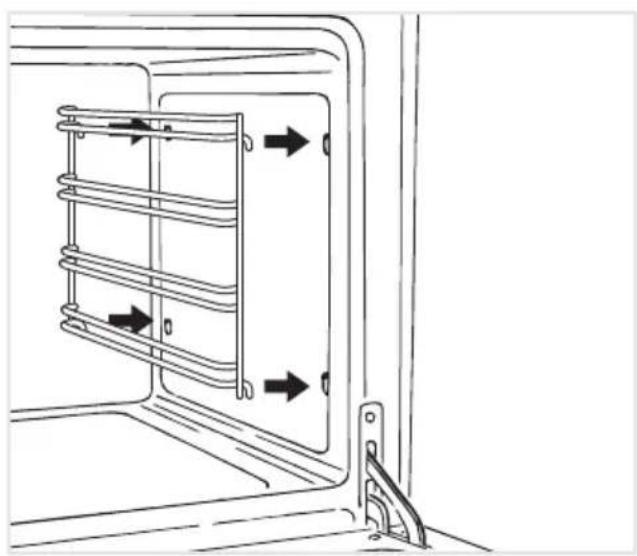
- Fit the side runner frames into the holes on the side walls inside the oven (fig. 4.1).
– Slide the drip pan and rack into the runners as shown in fig. 4.2.
The rack must be fitted so that the safety catch, which stops it sliding out, faces the inside of the oven.
-To dismantle, operate in reverse order.
natural_image
Technical line drawing of a mechanical component with spring-loaded housing and directional arrows indicating movement (no text or symbols)
natural_image
Technical diagram showing two views of a mechanical component with internal structure and mounting holes (no text or symbols)Fig. 4.2 Fig. 4.1
Replacing the Oven Lamp
WARNING: Ensure the appliance is switched off before replacing the lamp to avoid the possibility of electric shock.
- Let the oven cavity and the heating elements to cool down.
-Switch off the electrical supply.
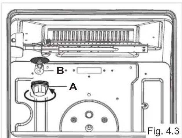
- Remove the protective cover "A" (fig. 4.3).
- Unscrew and replace the bulb “B” with a new one suitable for high temperatures (300°C) having the following specifications: 230V or 220-240V, E14 and same power (check watt power as stamped in the bulb itself) of the replaced bulb.
- Refit the protective cover "A".
Note: Oven bulb replacement is not covered by your guarantee.
Removing the Oven Door
Take care, the oven door is heavy. If you have any doubts, do not attempt to remove the door.
The oven door can easily be removed as follows:
-Open the door to the full extent (fig. 4.5).
- Open the lever "A" completely on the left and right hinges (fig. 4.6).
-Hold the door as shown in fig. 4.4.
-Gently close the door (fig. 4.7) until left and right hinge levers "A" are hooked to part "B" of the door (fig. 4.6).
-Withdraw the hinge hooks from their location following arrow "C" (fig. 4.8).
-Rest the door on a soft surface.
CAUTION: Do not use harsh abrasive cleaners or sharp metal scrapers to clean the oven door glass since they can scratch the surface, which may result in shattering of the glass.

natural_image
Technical line drawing of a mechanical bracket assembly (no text or symbols)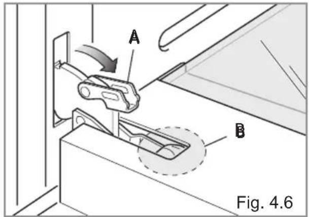

natural_image
Technical line drawing of a mechanical component or bracket assembly (no text or symbols)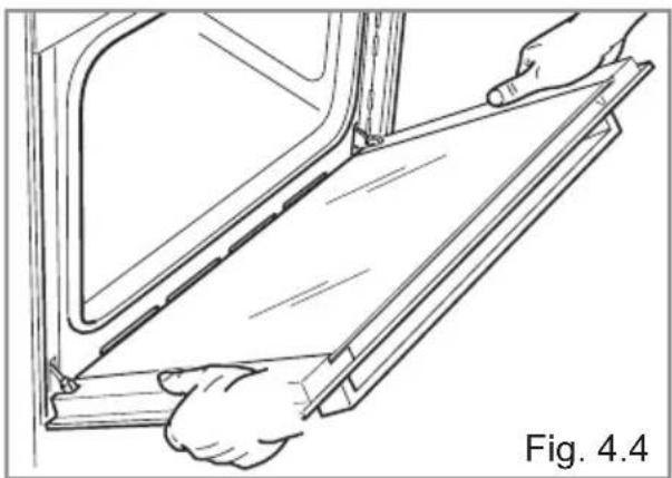
natural_image
Line drawing of hands installing or adjusting a panel inside a vehicle (no text or symbols)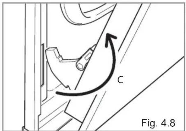
Refitting the Oven Door
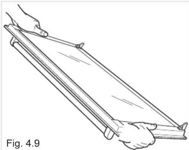
-Hold the door firmly (fig. 4.9).
-Insert the hinge tongues into the slots, making sure that the groove drops into place as shown in the fig. 4.10.
-Open the door to its full extent.
- Fully close the levers "A" on the left and right hinges, as shown in the figure fig. 4.11.
- Close the door and check that it is properly in place.
Removing and Replacing the Inner Door Glass Pane for Cleaning
If you wish to clean the inner glass of the door, make sure you follow the precautions and instructions very carefully.
Replacing the glass pane and the door incorrectly may result in damage to the oven and may void your warranty.
IMPORTANT!
-Take care, the oven door is heavy. If you have any doubts, do not attempt to remove the door.
- Make sure the oven and all its parts have cooled down. Do not attempt to handle the parts of a hot oven.
-Take extreme care when handling the glass pane. Avoid the edges of the glass bumping against any surface. This may result in the glass shattering.
-Do not use harsh abrasive cleaners or sharp metal scrapers to clean the oven door glass since they can scratch the surface, which may result in shattering of the glass.
- If you notice any sign of damage on any of the glass panes (such as chipping, or cracks), do not use the oven. Call your Authorised Service Centre or Customer Care.
- Make sure you replace the glass pane correctly. Do not use the oven without glass pane correctly in place.
- If the glass pane feels difficult to remove or replace, do not force it. Call your Authorised Repairer or Customer Care for help.
Note: service visits providing assistance with using or maintaining the oven are not covered by your warranty.
natural_image
Line drawing of two hands holding a long, thin wooden object (no text or symbols)
natural_image
Technical diagram of a mechanical component with directional arrows and a circled feature, labeled Fig. 4.10 (no readable text or symbols)
Removing the Inner Pane of Glass
The oven door is fitted with no. 2 panes:
-no. 1 outside;
-no. 1 inner.
To clean all panes on both sides it is necessary to remove the inner pane as follows:
- Lock the door open:
-Open the door to the full extent (fig. 4.12).
- Open the lever "A" completely on the left and right hinges (fig. 4.13).
-Gently close the door (fig. 4.14) until left and right hinge levers "A" are hooked to part "B" of the door (fig. 4.13).
- Remove the inner pane:
-Gently pull out the inner pane of glass (fig. 4.15).
-Clean the glass with an appropriate cleaner. Dry thoroughly, and place on a soft surface.
Now you can also clean the inside of the outer glass.

natural_image
Technical line drawing of a mechanical bracket assembly (no text or symbols)

natural_image
Technical line drawing of a mechanical component or bracket with diagonal lines and a labeled section (Fig. 4.14), no readable text or symbols beyond the label.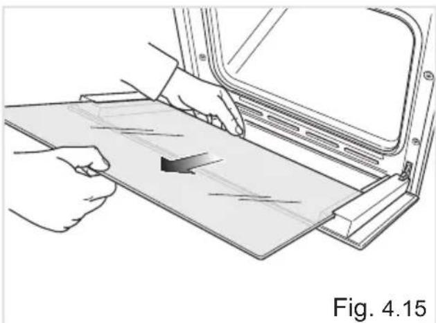
natural_image
Illustration of hands installing or adjusting a panel on a vehicle door frame, with no visible text or symbols.After Cleaning, Replace the Inner Glass Pane
When replacing the inner glass pane, make sure that:
-You replace the pane correctly, as shown. The pane must be in the position described below in order to fit into the door and to ensure that the oven operates safely and correctly.
-You take extra care not to bump the edges of the glass against any object or surface.
-You do not force the pane into place. If you are experiencing difficulties replacing the pane, remove it and start the process again from the beginning. If this still does not help, call Customer Care.
To reassemble the inner pane of the oven door operate as follows:
-
Make sure the door is locked open (see fig. 4.14).
-
Replace the inner pane:
-Check that the four rubber pads are in place ("D" in fig. 4.16).
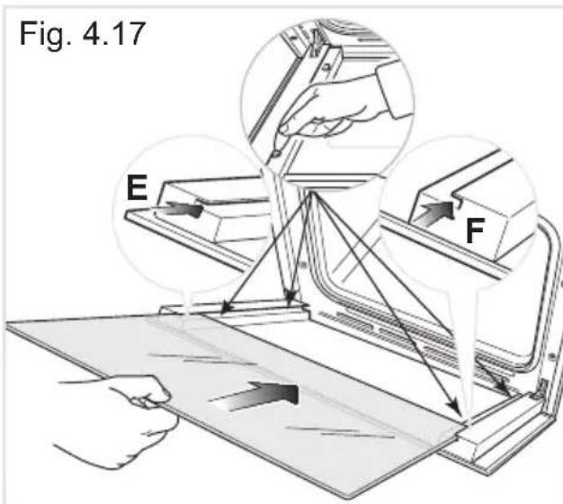
IMPORTANT: It is advisable, while refitting the glass, to keep pressed in position the four rubber pads "D", by a finger, to avoid breakage or slippage of the rubber pads themselves (Fig. 4.17).
-Check that you are holding the pane the correct way. You should be able to read the wording on it as it faces you.
- Insert the pane in the left "E" and right "F" slide guides (fig. 4.17), and gently slide it to the retainers "H" (Fig. 4.18).
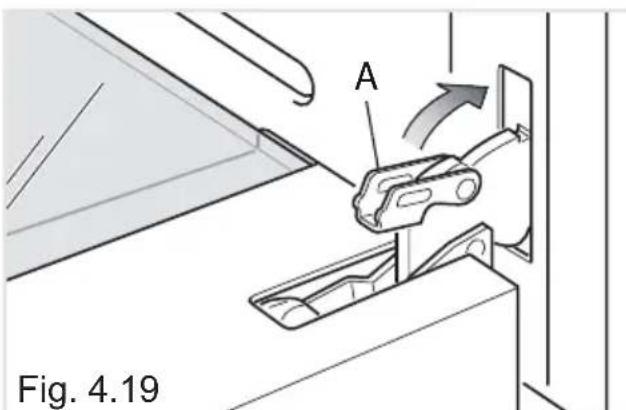
-Unlock the oven door by opening it completely and closing the lever "A" on the left and right hinges (fig. 4.19).

natural_image
Technical line drawing of a mechanical component with labeled point D (no text or symbols beyond label)Fig. 4.16

Do's and do not's
-Do always grill with the oven door ajar.
- Do read the user instructions carefully before using the oven for first time.
- Do allow the oven to heat for about two hours, before using for the first time, in order to expel any smell from the new oven insulation, without the introduction of food.
-Do clean your oven regularly.
-Do remove spills as soon as they occur.
- Do always use oven gloves when removing food shelves and trays from the oven.
- Do not allow children near the oven when in use.
- Do not allow fat or oils to build up in the oven tray, or oven base.
- Do not place cooking utensils or plates directly onto the oven base.
-Do not grill food containing fat without using the grid.
-Do not cover the grilling grid with aluminium-foil.
-Do not line the oven walls with aluminium foil.
-Do not use the oven tray for roasting.
- Do not place hot enamel parts in water. Leave them to cool first.
- Do not allow vinegar, coffee, milk, saltwater, lemon or tomato juice to remain in contact with enamel parts (inside the oven and on the oven tray).
- Do not use abrasive cleaners or powders that will scratch the surfaces and the enamel.
-Do not attempt to repair the internal workings of your oven.
-Do remove the protective film before the first use.
- Do not carry out any cleaning or maintenance without first disconnecting the appliance from the electrical supply.
– Fire risk! Do not store flammable material in the oven.
For Your Safety
The product should only be used for its intended purpose which is for the cooking of domestic foodstuffs.
Under no circumstances should any external covers be removed for servicing or maintenance except by suitably qualified personnel.
Important Notes
Installation, and any demonstration, information or adjustments are not included in the warranty.
The oven must be installed by a suitably qualified and registered person in accordance with the relevant Standards.
ATTENTION:
The appliance gets very hot, mainly around the cooking areas. It is very important that children are not left alone in the kitchen when you are cooking.
Advice for the installer
5 - INSTALLATION
Appliance installation and maintenance must only be carried out by QUALIFIED TECHNICIANS and in compliance with the local safety standards.
–Failure to observe this rule will invalidate the warranty.
- Always disconnect the appliance from the electrical supply before carrying out any maintenance operations or repairs.
- The walls surrounding the oven must be made of heat-resistant material.
-Taking care NOT to lift the oven by the door handle.
WARNING
When correctly installed, your product meets all safety requirements laid down for this type of product category.
However special care should be taken around the rear or the underneath of the appliance as these areas are not designed or intended to be touched and may contain sharp or rough edges, that may cause injury.
Location
The appliance may be installed in a kitchen, Kitchen/diner or a bed sitting room, but not in a room or space containing a bath or a shower.
The appliance must not be installed in a bed-sitting room of less than 20m 3 .
The appliance is designed and approved for domestic use only and should not be installed in a commercial, semi commercial or communal environment.
Your product will not be guaranteed if installed in any of the above environments and could affect any third party or public liability insurances you may have.
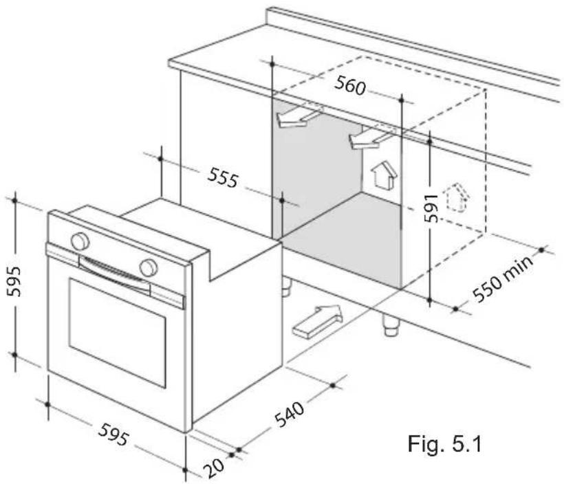
The oven is designed to fit into a cabinet of 600 mm width.
The oven can be built in or built under the kitchen units, but you must ensure that it is properly ventilated.
In the diagram the built in oven is ventilated by means of a space at the top of the kitchen cabinet.
There are many other methods of ventilating your oven.
Consult a qualified engineer for advice.
Important
Ensure that air can flow freely around the housing area.
Failure to allow adequate ventilation to the appliance may result in over heating or damage to adjacent units.
Lift the oven carefully into position on the shelf, taking care NOT to lift it by the door handle. If you lower the oven door, you will see 4 screw holes, 2 on each side of the oven.
The oven should then be secured to the housing by fitting screws into these holes.
Remember the housing should not be free standing but secured to the wall and/or adjacent fittings.

Fixing the Oven
Introduce the oven into the furniture opening and fix it with 4 screws (not supplied) as figure 5.3.
It is essential that the oven rests on a surface which will support its weight, as the screw fixing is only complementary.
Adjust the hinges of furniture doors adjacent to the oven to allow a 4-5 mm gap between the furniture door and the oven frame.
IMPORTANT:
To avoid damage to the lower trim please note the following instructions.
The lower trim is designed to allow for good air circulation and the correct opening of the oven door.
To ensure the trim is not damaged due to the appliance being placed on the floor, the appliance should be suitably supported as in illustration here below.
After installation the appliance door should be slowly opened to ensure no damage has occurred.
No responsibility for lower trim damage will be accepted if these instructions have not been followed.

natural_image
Line drawing of an open oven with screw fasteners, labeled as Fig. 5.3 (no text or symbols on the diagram itself)
Fig. 5.4
Provision for Ventilation
- The appliance should be installed into a room or space with an air supply in accordance with BS 5440-2: 2000.
-For rooms with a volume of less than 5m 3 - permanent ventilation of 100cm 2 free area will be required.
-For rooms with a volume of between 5m-3 and 10m3 a permanent ventilation of 50cm2 free area will be required unless the room has a door which opens directly to the outside air in which case no permanent ventilation is required.
-For rooms with a volume greater than 10m 3 - no permanent ventilation is required.
Note: Regardless of room size, all rooms containing the appliance must have direct access to the outside air via an openable window or equivalent.
- Where there are other fuel burning appliances in the same room, BS 5440-2: 2000 should be consulted to determine the correct amount of free area ventilation requirements.
- The above requirements allow also for use of a gas oven and grill but if there are other gas burning appliances in the same room, consult a qualified engineer.
6 - GAS SECTION
Gas Installation
Important Note
This appliance is supplied for use on NATURAL GAS or LPG (check the gas regulation label attached on the appliance).
- Appliances supplied for use on NATURAL GAS: they are adjusted for this gas only and cannot be used on any other gas (LPG) without modification. The appliances are manufactured for conversion to LPG.
- Appliances supplied for use on LPG: they are adjusted for this gas only and cannot be used on any other gas (NATURAL GAS) without modification. The appliances are manufactured for conversion to NATURAL GAS.
If the NATURAL GAS/LPG conversion kit is not supplied with the appliance this kit can be purchased by contacting the After-Sales Service.
Installation and Service Regulations (United Kingdom)
It is a legal requirement that all gas appliances are Installed & Serviced by a competent person in accordance with the current editions of the following Standards & Regulations or those regulations appropriate to the geographical region in which they are to be installed:
-Gas Safety (Installation & Use) Regulations
-Building Regulations
-British Standards
-Regulations for Electrical Installation
Installation and service of any gas product must be made by a suitably qualified and registered person competent on the type of product being installed or serviced and holding a valid certificate of competence for the work being carried out. Currently the proof of competence is the Accredited Certification Scheme (ACS) or S/NVQ that has been aligned to the ACS.
It is also a requirement that all businesses or self employed installers are members of a class of person approved by the Health and Safety Executive.
Failure to install the appliance correctly could invalidate any manufacturers warranty and lead to prosecution under the above quoted regulation.
Gas Connection
The installation of the gas appliance to Natural Gas or LP Gas must be carried out by a suitably qualified and registered installer. Installers shall take due account of the provisions of the relevant British Standards Code of Practice, the Gas Safety Regulations and the Building Standards (Scotland) (Consolidation) Regulations issued by the Scottish Development Department.
Installation to Natural Gas
Installation to Natural Gas must conform to the Code of Practice, etc.
The supply pressure for Natural Gas is 20 mbar.
The installation must conform to the relevant British Standards.
Installation to LP Gas
When operating on Butane gas a supply pressure of 28-30 mbar is required.
When using Propane gas a supply pressure of 37 mbar is required.
The installation must conform to the relevant British Standards.
Warning: Only a suitably qualified and registered installer, also with technical knowledge of electricity should install the appliance. He should observe the Regulations and Codes of Practice governing such installation of gas appliances.
Note: It is recommended that the gas connection to the appliance is installed with a flexible connecting tube made to BS5386.
Notes:
- Flexible hoses can be used where the sited ambient temperature of the hose does not exceed 70°C. These hoses must be manufactured in accordance with BS669 part 1 and be of the correct construction for the type of gas being used.
Gas hoses designed for natural gas MUST NOT be used for supplying LPG gas (LPG gas hoses can be identified by a either a red band or stripe on the rubber outer coating of the hose). The hose should not be crushed or trapped or be in contact with sharp or abrasive edges.
If installation is to be carried out using a flexible connector (to BS669), then the following points must be adhered to:
Note: The gas installation pipes and the final connection to the appliance connecting pipe shall be sufficient size to maintain the heat output of the appliance as specified under installation.
- The appliance flexible connector should not be subject to undue forces, either in normal use whilst being connected or disconnected.
- The appliance flexible connector should not be subject to excessive heat by direct exposure to flue products or by contact with hot surfaces.
- The socket into which the plug of the appliance flexible connector fits should be permanently attached to a firmly fixed gas installation pipe and positioned such that the hose hangs freely downwards.
- The appliance flexible connector should be positioned such that it will not suffer mechanical damage; eg abrasion from the surrounding kitchen furniture which may be moved in use, such as a door or drawer, or by being trapped by a stability device.
- The plug-in connector should be accessible for disconnection after moving the appliance.

natural_image
Line drawing of a microwave oven with a close-up inset showing internal components (no text or symbols)Installing the Test Point Adaptor

Fig. 6.2
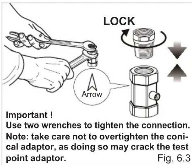
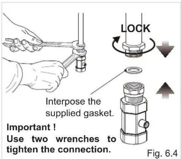
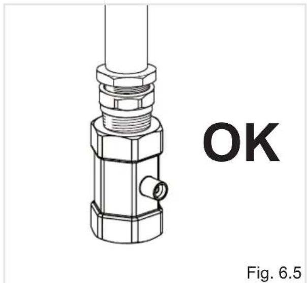
Using a suitable leak detection fluid solution (e.g. Rocol) check each gas connection one at a time by brushing the solution over the connection.
The presence of bubbles will indicate a leak.
If there is a leak, tighten the fitting and then recheck for leaks.
IMPORTANT! Do not use a naked flame to test for leaks.
MAINTENANCE AND CONVERSION TO NATURAL GAS OR TO LPG
| Table for the Choice of the Injectors Cat: II 2H3+ GB | ||||||
| BURNERS | Nominal power [kW] | Reduced power [kW] | LPG G30 (28-30 mbar) G31 (37 mbar) | Natural Gas G20 (20 mbar) | ||
| ∅ injector [1/100 mm] | Ring opening [mm] | ∅ injector [1/100 mm] | Ring opening [mm] | |||
| Oven 2,70 0,65 78 | Fully open (*) | 120 2 (*) | ||||
| Grill 2,10 - 72 | Fully open (*) | 110 2 (*) | ||||
(*) = Reference value
| AIR VENT NECESSARY FOR GAS COMBUSTION = (2 m3/h x kW) | |
| BURNERS Air necessary for combustion [m 3/h] | |
| Oven 5,40 | |
| Grill 4,20 | |
IMPORTANT: All intervention regarding installation maintenance and conversion of the appliance must be fulfilled with original factory parts.
The manufacturer declines any liability resulting from the non-compliance of this obligation.
Operations to Be Executed for the Replacement of the Injectors of the Oven and Grill Burners
Some models are provided with a set of injectors for the various types of gas.
If the injectors are not supplied they can be obtained from the "Service Centre".
Select the injectors to be replaced according to the "Table for the choice of the injectors".
The nozzle diameters, expressed in hundredths of a millimetre, are marked on the body of each injector.
Oven Burner
-Lift and remove the lower panel inside the oven.
- Unscrew and remove the burner securing screw "A" (fig. 6.6).
- Withdraw the burner as shown in figure 6.7 and rest it inside the oven. Take care not to damage the safety valve probe and the electric ignition electrode.
- Using a 7 mm box spanner, unscrew the injector (indicated by the arrow in fig. 6.7) and replace it with a new one selected in accordance with the “Table for the choice of the injectors”.
- Regulate the air supply to the oven burner as indicated in the section "Regulation of air supply to oven and grill bur-
ners"; then replace the burner and the other components repeating the above steps in reverse order.
IMPORTANT: Check the correct operation of the safety valve and the ignition electrode.

natural_image
Technical diagram of a device interior showing internal components and labeled parts (A), with no readable text or symbols beyond label.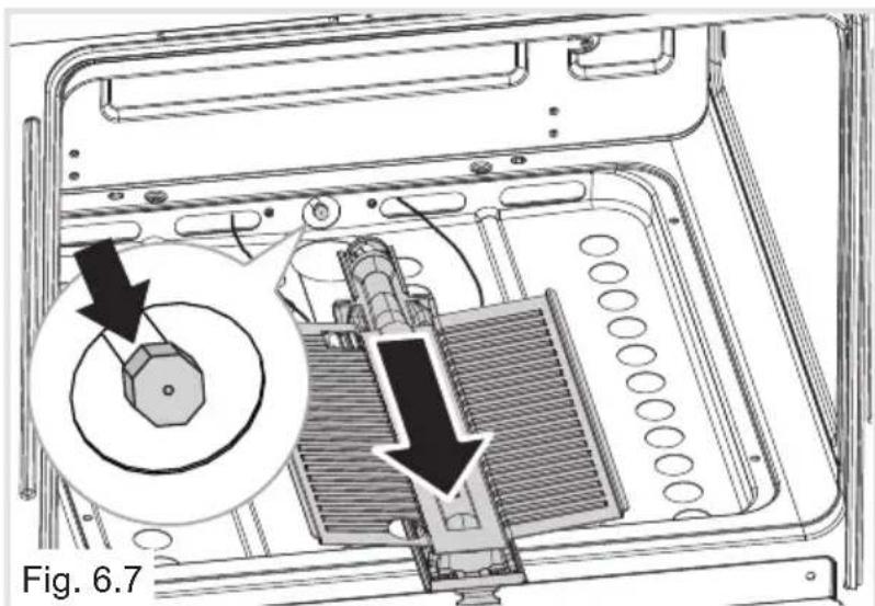
natural_image
Technical diagram of a mechanical assembly with a magnified inset showing internal components (no text or symbols)Grill Burner
- Unscrew and remove the burner securing screw "A" (fig. 6.8).
- Withdraw the burner as shown in figure 6.9. Take care not to damage the safety valve probe and the electric ignition electrode.
- Using a 7 mm box spanner, unscrew the injector (indicated by the arrow in fig. 6.9) and replace it with a new one selected in accordance with the “Table for the choice of the injectors”.
- Regulate the air supply to the grill burner as indicated in the section "Regulation of air supply to oven and grill burners"; then replace the burner repeating the above steps in reverse order.
IMPORTANT: Check the correct operation of the safety valve and the ignition electrode.

natural_image
Technical line drawing of a mechanical device with labeled component A, showing internal components and no readable text or symbols.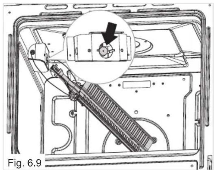
natural_image
Technical line drawing of a mechanical assembly inside a device frame, showing internal components and a magnified inset (no text or symbols)Regulation of Air Supply to Oven and Grill Burners
To regulate the air supply it is necessary to remove the burners from their housings (figs. 6.6 - 6.8).
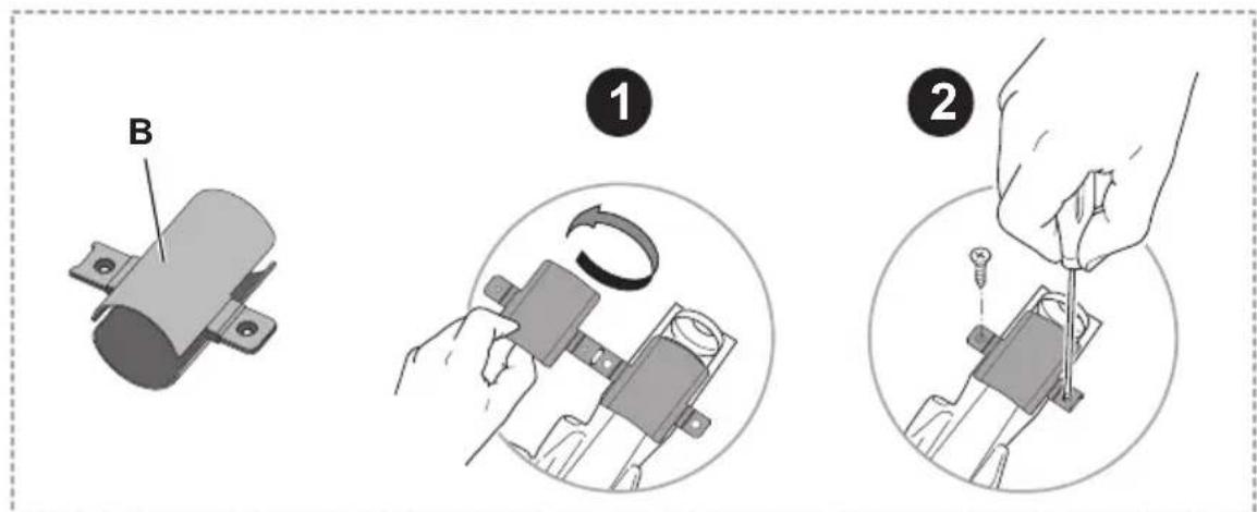
- Using a cross-head screwdriver, slacken the screws “A” securing the air flow regulation collar “B” (fig. 6.10) and move the collar forward or backward to increase or reduce the air aperture in accordance with gas type and the indications in the ‘Table for the choice of the injectors’.
IMPORTANT: If the air flow regulation collar “B” is not already fitted on the burner (e.g. oven burner set in the factory for LPG use), it is supplied with the kit for the gas conversion. In this case the air flow regulation collar “B” shall be fitted as indicated in figure 6.10:
- the collar "B" shall be folded around the burner (one half part at the top and one half part at the bottom);
- the throttled section shall be oriented toward the burner deflector (opposite side with respect to the injector).
-Replace and light the burners to check the flames.
Fig. 6.10
![6.10 Grill burner Ring opening [mm] (see the "Table for the choice of the injectors") Oven burner A B](/content/2026/05/965491/images/7f058bdab1625dbc46e8abd64c8a8e7272eed5022e2ee56d4cb05f8d61f815e1.jpg)
| Flame faulty in primary air | Flame correct | Flame with excess primary air |
| flong, yellow and trembling | clear interior blue cone | short and sharp too blue interior cone tending to detach |
| CAUSE | ||
| air regulating tube, too closed | correct distance of the tube | air regulating tube, too open |

Flame correct

Flame faulty in primary air
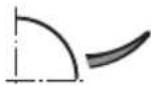
Flame with excess primary air
Adjustment of the Oven Burner Minimum
This needs to be done only for the oven burner (the grill is a fixed capacity) by acting on the thermostat.
In the minimum position the flame must have a length of about 4 mm and must remain lit even with a brusque passage from the maximum position to that of minimum.
The flame adjustment is done in the following way:
- Turn on the oven burner by setting the thermostat knob on maximum position "240".
- Remove the knob and unscrew the by-pass screw "G" (fig. 6.11) about three times by passing a small flat screwdriver (∅ 3 mm blade, 100 mm length) through the control panel opening.
Note: for the models with glass control panel, for easy access to the by-pass screw, it is suggested to remove the control panel itself (fig. 6.12). To do that unscrew the two screws on the bottom side of the control panel and then move, toward the outside, the bottom edge of the glass until the complete extraction of the bottom fixing tongues.
Then let it slide downwards to disengage the top fixing tongues.
- Re-mount the knob and let the oven heat up for about 15 minutes, then bring the knob to the minimum position "130" to operate the thermostat by-pass.
- After having removed the knob again and being very careful not to turn the thermostat rod, slowly screw the by-pass screws "G" (fig. 6.11) until you obtain a flame of 3 - 4mm in height.
-Turn off the burner and reassemble the knob.
N.B. For G30/G31 (LPG) the by-pass screw must be fixed thoroughly.


7 - ELECTRICAL SECTION
IMPORTANT: Installation must be carried out according to the manufacturer's instructions. Incorrect installation may cause harm and damage to people, animals or property, for which the manufacturer accepts no responsibility.
Before carrying out any work on the electrical section of the appliance, it must be disconnected from the mains.
Connection to a good earth wiring system is absolutely essential.
The manufacturer accepts no responsibility for any inconvenience caused by failure to comply with this rule.
This appliance must be installed by a qualified technician according with the current local regulations and in compliance with the manufacturer instructions.
This appliance is supplied with a moulded 13 amp three pin mains plug with a 3 amp fuse fitted. Should the fuse require replacement, it must be replaced with a fuse rated at 3 amp and approved by ASTA or BSI to BS 1362.
The plug contains a removable fuse cover that must be refitted when the fuse is replaced. In the event of the fuse cover being lost or damaged, the plug must not be used until a replacement cover has been obtained. Replacement fuse covers can be purchased from your nearest electrical dealer and must be the same colour as the original.
IF THE MOULDED MAINS PLUG IS UNSUITABLE FOR THE SOCKET OUTLET IN YOUR HOME OR IS REMOVED FOR ANY OTHER REASON, THEN THE FUSE SHOULD BE REMOVED AND THE CUT OFF PLUG DISPOSED OF SAFELY TO PREVENT THE HAZARD OF ELECTRIC SHOCK.
THERE IS A DANGER OF ELECTRICAL SHOCK IF THE CUT OFF PLUG IS INSERTED INTO ANY 13 AMP SOCKET OUTLET.
If a replacement plug is to be fitted, please observe the wiring code shown below.
A properly earthed three pin plug (fused at 3 amps, to BS 1362 ASTA approved) must be used. As the colours of the wires in the mains lead of this appliance may not correspond with the coloured markings identifying the terminals in your plug, proceed as follows:
- The wire which is coloured GREEN & YELLOW must be connected to the terminal in the plug which is marked with letter "E" or by the Earth symbol " 1= " or coloured GREEN & YELLOW.
- The wire which is coloured BLUE must be connected to the terminal which is marked with the letter "N" or coloured BLACK.
- The wire which is coloured BROWN must be connected to the terminal which is marked with the letter "L" or coloured RED.

CONNECTION OF THE POWER SUPPLY CABLE
- Unhook the terminal board cover by inserting a screwdriver into the two hooks "A" (fig. 7.2).
- Open the cable gland by unscrewing screw "F" (fig. 7.3), unscrew the terminal screws and remove the cable.
- The new supply cable, of suitable type and section, is connected to the terminal board following the diagram of fig. 7.4.
WARNING: If the power supply cable is damaged, it must be replaced only by an authorised service agent in order to avoid a hazard.
FEEDER CABLE SECTION TYPE "H05RR-F" or "H05V2V2-F"
230 V ac 3 × 0.75 mm2

natural_image
Technical line drawing of a mechanical clamp or connector assembly with labeled component 'F', no readable text or symbols beyond label and figure label

8 - GUARANTEE
Your new “KENWOOD” product comes with 12-month guarantee covering all parts and labour.
If your appliance proves to be defective as a result of faulty materials or workmanship during the guarantee period, these parts will be repaired or replaced free of charge.
AFTER SALES SERVICE
Should you require service, spares or product information and advice:
• Please Telephone 0843 362 1934.
• Details of your purchase receipt will be required if you require service within the first 12-month of purchase.
-
The rights and benefits under this guarantee are additional to your statutory rights, which are not affected by this guarantee.
-
The manufacturer undertakes within the specified period, to repair or replace free of charge any parts of the appliance found to be defective provided that:
• We are promptly informed of the defect.
- The appliance is installed and used in accordance with the written instructions enclosed with the appliance.
- The appliance is used only on an electrical supply as indicated on the rating label fixed to the appliance.
- The appliance has not been altered in any way or subject to misuse or repaired by a person other than an authorised service agent.
-
No rights are given under this guarantee to a person acquiring the appliance second hand or for commercial, semi-commercial or communal use.
-
This guarantee applies throughout the UK and Channel Islands.
-
Any repaired or replacement appliances will be guaranteed on these terms for the unexpired portion of the guarantee.
The manufacturer cannot be held responsible for possible inaccuracies due to printing or transcription errors in the present booklet.
The manufacturer reserves the right to make all modifications to its products deemed necessary for manufacture or commercial reasons at any moment and without prior notice, without jeopardising the essential functional and safety characteristics of the appliances.
KENWOOD
- KENWOOD
- CONTENTS Page Number
- Dear Customer,
- Declaration of CE Conformity
- Before Using for the First Time
- Using the Oven for the First Time
- Important Precautions and Recommendations for Use of Electrical Appliances
- Important Safeguards & Recommendations
- This film must be removed before using the appliance.
- - CONTROL PANEL
- Controls Description
- Notes:
- CAUTION:
- - HOW TO USE THE FAN OVEN
- Technical Features
- Operating Principles
- Cooling Fan Motor
- ATTENTION:
- IMPORTANT NOTES:
- Oven Burner
- Thermostat
- Lighting of Oven Burner
- Lighting of Gas Grill Burner
- Cooking With Gas Oven
- Fan Motor
- Cooking With Fan Assisted Gas Oven (Oven Burner and Fan Motor - fig. 2.8)
- Defrosting Frozen Foods (Fan Motor Only - fig. 2.9)
- Oven Light
- Traditional Grilling
- WARNING !!
- Cooking Guide
- Safety
- - MINUTE COUNTER
- 60' Timer
- IMPORTANT WARNING:
- - CLEANING AND MAINTENANCE
- Care and Maintenance
- WARNING
- Inside of Oven
- Enamelled Parts
- Stainless Steel, Aluminium, Painted Parts and Silk-screen Printed Surfaces
- Glass Control Panel
- Assembling and Dismantling of the Side Runner Frames
- Replacing the Oven Lamp
- Removing the Oven Door
- Refitting the Oven Door
- Removing and Replacing the Inner Door Glass Pane for Cleaning
- IMPORTANT!
- Removing the Inner Pane of Glass
- After Cleaning, Replace the Inner Glass Pane
- Do's and do not's
- For Your Safety
- Important Notes
- Advice for the installer
- - INSTALLATION
- Location
- Important
- Fixing the Oven
- IMPORTANT:
- Provision for Ventilation
- Note: Regardless of room size, all rooms containing the appliance must have direct access to the outside air via an openable window or equivalent.
- - GAS SECTION
- Gas Installation
- Important Note
- Installation and Service Regulations (United Kingdom)
- Gas Connection
- Installation to Natural Gas
- Installation to LP Gas
- Installing the Test Point Adaptor
- MAINTENANCE AND CONVERSION TO NATURAL GAS OR TO LPG
- Operations to Be Executed for the Replacement of the Injectors of the Oven and Grill Burners
- Grill Burner
- Regulation of Air Supply to Oven and Grill Burners
- Adjustment of the Oven Burner Minimum
- - ELECTRICAL SECTION
- CONNECTION OF THE POWER SUPPLY CABLE
- FEEDER CABLE SECTION TYPE "H05RR-F" or "H05V2V2-F"
- - GUARANTEE
- AFTER SALES SERVICE
Brand : KENWOOD
Model : KS 100 G
Category : Oven