WNAP-7320 - Access Point Planet - Free user manual and instructions
Find the device manual for free WNAP-7320 Planet in PDF.


| Type of Product | Wireless Access Point |
| Brand | Planet |
| Model | WNAP-7320 |
| Dimensions (W x D x H) | 200 mm x 200 mm x 40 mm |
| Weight | 300 g |
| Power Supply | PoE (802.3af) or 12V DC |
| Wireless Standard | 802.11n, 2.4 GHz |
| Maximum Data Rate | 300 Mbps |
| Number of SSIDs | 8 |
| Security Features | WPA/WPA2, MAC filtering, SSID broadcast disable |
| Management | Web-based, SNMP |
| Mounting | Wall/ceiling mountable |
| Operating Temperature | 0°C to 50°C |
| Humidity | 10% to 90% non-condensing |
| Cleaning Instructions | Wipe with a dry, soft cloth |
| Safety Precautions | Keep away from water and heat sources |
| Spare Parts and Repairability | No user-serviceable parts inside |
| General Information | Indoor use only |
Frequently Asked Questions - WNAP-7320 Planet
User questions about WNAP-7320 Planet
0 question about this device. Answer the ones you know or ask your own.
Ask a new question about this device
Download the instructions for your Access Point in PDF format for free! Find your manual WNAP-7320 - Planet and take your electronic device back in hand. On this page are published all the documents necessary for the use of your device. WNAP-7320 by Planet.
USER MANUAL WNAP-7320 Planet
802.11a/n Wireless Outdoor AP
WNAP-7320

natural_image
Woman in business attire using a laptop on a stone staircase (no visible text or symbols)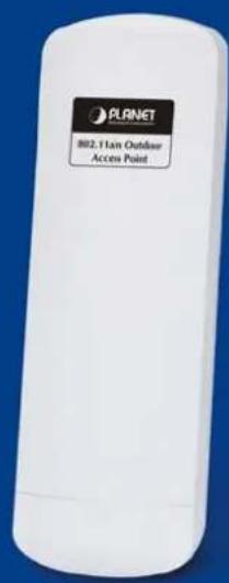
Copyright
Copyright © 2013 by PLANET Technology Corp. All rights reserved. No part of this publication may be reproduced, transmitted, transcribed, stored in a retrieval system, or translated into any language or computer language, in any form or by any means, electronic, mechanical, magnetic, optical, chemical, manual or otherwise, without the prior written permission of PLANET.
PLANET makes no representations or warranties, either expressed or implied, with respect to the contents hereof and specifically disclaims any warranties, merchantability or fitness for any particular purpose. Any software described in this manual is sold or licensed "as is". Should the programs prove defective following their purchase, the buyer (and not this company, its distributor, or its dealer) assumes the entire cost of all necessary servicing, repair, and any incidental or consequential damages resulting from any defect in the software. Further, this company reserves the right to revise this publication and to make changes from time to time in the contents hereof without obligation to notify any person of such revision or changes.
All brand and product names mentioned in this manual are trademarks and/or registered trademarks of their respective holders.
Federal Communication Commission Interference Statement
This equipment has been tested and found to comply with the limits for a Class A digital device,
FCC pursuant to part 15 of the FCC Rules. These limits are designed to provide reasonable protection against harmful interference when the equipment is operated in a commercial environment. This equipment generates, uses, and can radiate radio frequency energy and, if not installed and used in accordance with the instruction manual, may cause harmful interference to radio communications. Operation of this equipment in a residential area is likely to cause harmful interference in which case the user will be required to correct the interference at his/her own expense. Any changes or modifications not expressly approved by PLANET could void the user's authority to operate this equipment under the rules and regulations of the FCC.
FCC Caution:
To assure continued compliance, (example-use only shielded interface cables when connecting to computer or peripheral devices) any changes or modifications not expressly approved by the party responsible for compliance could void the user's authority to operate the equipment.
This device complies with Part 15 of the FCC Rules. Operation is subject to the Following two conditions:
(1) This device may not cause harmful interference
(2) This Device must accept any interference received, including interference that may cause undesired operation.
Federal Communication Commission (FCC) Radiation Exposure Statement
This equipment complies with FCC radiation exposure set forth for an uncontrolled environment. In order to avoid the possibility of exceeding the FCC radio frequency exposure limits, human proximity to the antenna shall not be less than 20 cm (8 inches) during normal operation.
This is a Class B product. In a domestic environment, this product may cause radio interference, in which case the user may be required to take adequate measures.
Energy Saving Note of the Device
This power required device does not support Standby mode operation.
For energy saving, please remove the DC-plug to disconnect the device from the power circuit. Without remove the DC-plug, the device still consuming power from the power circuit. In the view of Saving the Energy and reduce the unnecessary power consuming, it is strongly suggested to remove the DC-plug for the device if this device is not intended to be active.
R&TTE Compliance Statement
This equipment complies with all the requirements of DIRECTIVE 1999/5/CE OF THE EUROPEAN PARLIAMENT AND THE COUNCIL OF 9 March 1999 on radio equipment and telecommunication terminal Equipment and the mutual recognition of their conformity (R&TTE).
The R&TTE Directive repeals and replaces in the directive 98/13/EEC (Telecommunications Terminal Equipment and Satellite Earth Station Equipment) As of April 8, 2000.
Safety
This equipment is designed with the utmost care for the safety of those who install and use it. However, special attention must be paid to the dangers of electric shock and static electricity when working with electrical equipment. All guidelines of this and of the computer manufacture must therefore be allowed at all times to ensure the safe use of the equipment.
WEEE regulation

To avoid the potential effects on the environment and human health as a result of the presence of hazardous substances in electrical and electronic equipment, end users of electrical and electronic equipment should understand the meaning of the crossed-out wheeled bin symbol. Do not dispose of WEEE as unsorted municipal waste and have to collect such WEEE separately.
Revision
User's Manual for PLANET 802.11a/n Wireless Outdoor Access Point
Model: WNAP-7320
Rev: 1.0 (March, 2013)
Part No. EM-WNAP-7320_v1.0 (2081-E10530-000)
CONTENTS
Chapter 1.Product Introduction....1
1.1 Package Contents .... 1
1.2 Product Description....2
1.3 Product Features....5
1.4 Product Specification 6
Chapter 2. Hardware Installation ...... 9
2.1 Hardware Description....9
2.1.1 The Side Panel – LED 10
2.1.2 The Rear Panel – Mounting Design 11
2.1.3 The Bottom Panel – Port 12
Chapter 3. Connecting to the AP ....13
3.1 Preparation before Installation 13
3.1.1 Professional Installation Required....13
3.1.2 Safety Precautions....13
3.2 Installation Precautions....13
3.3 Installing the AP 15
3.4 Standard Pole Mounting....17
3.5 Adjustable Pole Mounting....17
3.6 Wall Mounting....18
Chapter 4. Quick Installation Guide ...... 19
4.1 Manual Network Setup - TCP/IP Configuration....19
4.1.1 Configure the IP Address Manually 19
4.2 Starting Setup in the Web UI....23
Chapter 5.Configuring the AP....25
5.1 Status....25
5.2 Easy Setup....28
5.3 Advanced....29
5.3.1 Advanced - Management....29
5.3.1.1. Web Interface Settings (Password)....30
5.3.1.2. Firmware Upgrade 30
5.3.1.3. Configuration....31
5.3.1.4. Load Factory Defaults 32
5.3.1.5. Reboot System 32
5.3.1.6. Scheduling Reboot....33
5.3.2 Advanced – Advanced Settings....33
5.3.2.1. Time Zone Settings....34
5.3.2.2. DDNS Settings....34
5.3.2.3. UPNP Settings 38
5.3.2.4. SNMP Settings....39
5.3.3 Advanced – Operation Mode....39
5.3.3.1. AP Router (AP+Router) 40
5.3.3.2. AP Bridge (AP+WDS) 40
5.3.3.3. Client Router (WISP) 41
5.3.3.4. Client Bridge (Slave AP Bridge) 45
5.3.4 Advanced – System Log....46
5.3.5 Advanced – Tools 46
5.3.5.1. Ping....47
5.3.5.2. Traceroute....47
5.3.5.3. Throughput....48
5.4 Firewall Settings....48
5.4.1 MAC/IP/Port Filtering 48
5.4.2 Virtual Server 50
5.4.3 DMZ 51
5.4.4 Firewall....51
5.4.5 QoS....52
5.4.6 Content Filtering .... 54
5.4.6.1. Webs URL Filter Settings....54
5.4.6.2. Web Host Filter Settings 55
5.5 Network Settings....55
5.5.1 WAN....55
5.5.1.1. Static (Fixed IP)....55
5.5.1.2. Cable/Dynamic IP (DHCP)....56
5.5.1.3. PPPoE (ADSL)....57
5.5.1.4. IPSEC 58
5.5.1.5. PPTP 62
5.5.1.6. L2TP 63
5.5.2 LAN 64
5.5.2.1. DHCP Server 65
5.5.2.2. DHCP Relay....65
5.5.3 VLAN....66
5.5.4 Advanced Routing 67
5.5.5 IPv6....68
5.6 Wireless Settings....69
5.6.1 Basic 69
5.6.1.1. Wireless Mode – Access Point....69
5.6.1.2. Wireless Mode – WDS Access Point 71
5.6.1.3. Wireless Mode – WDS Repeater ....73
5.6.1.4. Wireless Mode – WDS Client....75
5.6.2 Profile Settings....77
5.6.3 Advanced....79
5.6.4 Access Control....80
5.7 Logout....81
Appendix A: FAQ....82
A.1 What and how to find my PC's IP and MAC address? 82
A.2 What is Wireless LAN?......82
A.3 What are ISM bands?......82
A.4 How does wireless networking work?......82
A.5 What is BSSID?......83
A.6 What is ESSID?......83
A.7 What are potential factors that may causes interference?......83
A.8 What are the Open System and Shared Key authentications?......84
A.9 What is WEP?......84
A.10 What is Fragment Threshold? 84
A.11 What is RTS (Request to Send) Threshold? 85
A.12 What is Beacon Interval? 85
A.13 What is Preamble Type?......85
A.14 What is SSID Broadcast?......85
A.15 What is Wi-Fi Protected Access (WPA)? 86
A.16 What is WPA2?......86
A.17 What is 802.1x Authentication?......86
A.18 What is Temporal Key Integrity Protocol (TKIP)?......86
A.19 What is Advanced Encryption Standard (AES)?......86
A.20 What is Inter-Access Point Protocol (IAPP)?......86
A.21 What is Wireless Distribution System (WDS)?......87
A.22 What is Universal Plug and Play (UPnP)?......87
A.23 What is Maximum Transmission Unit (MTU) Size? 87
A.24 What is Clone MAC Address? 87
A.25 What is DDNS?......87
A.26 What is NTP Client?......87
A.27 What is VPN?......87
A.28 What is IPSEC? 88
A.29 What is WLAN Block Relay between Clients? 88
A.30 What is WMM?......88
A.31 What is WLAN ACK TIMEOUT? 88
A.32 What is Modulation Coding Scheme (MCS)?......88
A.33 What is Frame Aggregation?......88
A.34 What is Guard Intervals (GI)? 89
Appendix B: Configuring the PC in Windows 7....90
Appendix C: Use Planet Smart Discovery to find AP 93
Appendix D: Specifications....94
Chapter 1. Product Introduction
1.1 Package Contents
Thank you for choosing PLANET WNAP-7320. Before installing the AP, please verify the contents inside the package box.
WNAP-7320 Wireless AP Quick Installation Guide CD-ROM

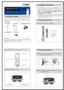
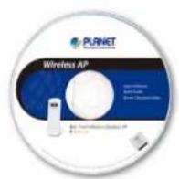
(User Manual included)
PoE Injector & Power Cord Mounting Tie x 2
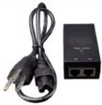
natural_image
Black cable and network device with two ports (no visible text or symbols)

If there is any item missed or damaged, please contact the seller immediately.
1.2 Product Description .2 Product Description
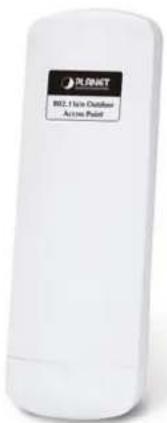
High Power Outdoor Wireless Coverage
PLANET Technology introduces the latest high power outdoor wireless LAN solution - the 300Mbps outdoor wireless AP, WNAP-7320. It provides higher transmit power, better performance, widely coverage and stable connection than standard outdoor wireless AP. As an IEEE 802.11a/n compliant wireless device, the WNAP-7320 is able to give stable and efficient wireless performance for long distance application; while designed with IEEE 802.11n standard and 2T2R MIMO technology makes it possible to deliver six times faster data rate up to 300Mbps than normal 802.11a wireless device. It also features adjustable output power up to 500mW to extend higher coverage in outdoor long range application.
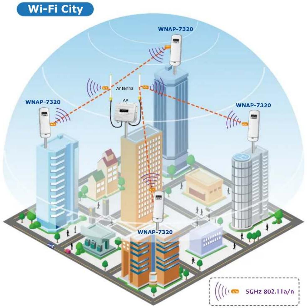
Multiple Operating & Wireless Modes
The WNAP-7320 supports multiple wireless communication connectivity (AP / Client CPE / WDS PtP / WDS PtMP / Repeater) allowing for various application requirements and thus it gives users more comprehensive experience when using the WNAP-7320. It helps users to easily build a wireless network and extend the wireless range of existing wireless network.
The WNAP-7320 also supports WISP mode, so CPE users could easily connect to Internet via WISP provider or connect to a wired network.
flowchart
graph LR
    A["Internet"] --> B["Cable/xDSL Modem"]
    B --> C["WAN"]
    C --> D["WNAP-7320"]
    D --> E["Client"]
    D --> F["Client"]
    G["AP Router Mode"] --> H["Ap Router Mode"]
flowchart
graph LR
    A["Internet"] --> B["WNAP-7320"]
    B --> C["Switch"]
    C --> D["Clients"]
    B --> E["Client"]
    style A fill:#f9f,stroke:#333
    style B fill:#ccf,stroke:#333
    style C fill:#cfc,stroke:#333
    style D fill:#fcc,stroke:#333
    style E fill:#ffc,stroke:#333
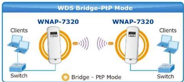
flowchart
graph LR
    A["WNAP-7320"] -->|Wireless Signal| B["Switch"]
    C["WNAP-7320"] -->|Wireless Signal| D["Switch"]
    E["WNAP-7320"] -->|Wireless Signal| F["Switch"]
    G["WNAP-7320"] -->|Wireless Signal| H["Switch"]
    I["WNAP-7320"] -->|Wireless Signal| J["Switch"]
    K["WNAP-7320"] -->|Wireless Signal| L["Switch"]
    M["WNAP-7320"] -->|Wireless Signal| N["Switch"]
    O["WNAP-7320"] -->|Wireless Signal| P["Switch"]
    Q["WNAP-7320"] -->|Wireless Signal| R["Switch"]
    S["WNAP-7320"] -->|Wireless Signal| T["Switch"]
    U["WNAP-7320"] -->|Wireless Signal| V["Switch"]
    W["WNAP-7320"] -->|Wireless Signal| X["Switch"]
    Y["WNAP-7320"] -->|Wireless Signal| Z["Switch"]
    AA["WNAP-7320"] -->|Wireless Signal| AB["Switch"]
    AC["WNAP-7320"] -->|Wireless Signal| AD["Switch"]
    AE["WNAP-7320"] -->|Wireless Signal| AF["Switch"]
    AG["WNAP-7320"] -->|Wireless Signal| AH["Switch"]
    AI["WNAP-7320"] -->|Wireless Signal| AJ["Switch"]
    AK["WNAP-7320"] -->|Wireless Signal| AL["Switch"]
    AM["WNAP-7320"] -->|Wireless Signal| AN["Switch"]
    AO["WNAP-7320"] -->|Wireless Signal| AP["Switch"]
    AQ["WNAP-7320"] -->|Wireless Signal| AR["Switch"]
    AS["WNAP-7320"] -->|Wireless Signal| AT["Switch"]
    AU["WNAP-7320"] -->|Wireless Signal| AV["Switch"]
    AW["WNAP-7320"] -->|Wireless Signal| AX["Switch"]
    AY["WNAP-7320"] --> AZ["Client"]
    BA["WNAP-7320"] --> BB["Client"]
    BC["WNAP-7320"] --> BD["Client"]
    BE["WNAP-7320"] --> BF["Client"]
    BG["WNAP-7320"] --> BH["Client"]
    BI["WNAP-7320"] --> BJ["Client"]
    BK["WNAP-7320"] --> BL["Client"]
    BM["WNAP-7320"] --> BN["Client"]
    BO["WNAP-7320"] --> BP["Client"]
    BP["WNAP-7320"] --> BQ["Client"]
    BR["WNAP-7320"] --> BS["Client"]
    BT["WNAP-7320"] --> BU["Client"]
    BV["WNAP-7320"] --> BW["Client"]
    BX["WNAP-7320"] --> BY["Client"]
    BZ["WNAP-7320"] --> CA["Client"]
    CB["WNAP-7320"] --> CD["Client"]
    CE["WNAP-7320"] --> CF["Client"]
    DG["WNAP-7320"] --> DH["Client"]
    DI["WNAP-7320"] --> DJ["Client"]
    DK["WNAP-7320"] --> DL["Client"]
    DM["WNAP-7320"] --> DE["Client"]
    DF["WNAP-7320"] --> DG
    DG --> DG
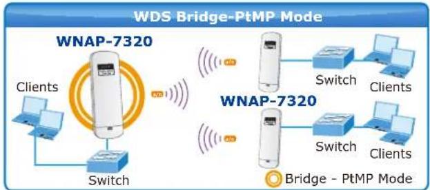
flowchart
graph TD
    A["WNAP-7320"] -->|Switch| B["WNAP-7320"]
    A -->|Clients| C["Client"]
    A -->|Switch| D["Switch"]
    E["WNAP-7320"] -->|Switch| F["WNAP-7320"]
    E -->|Clients| G["Clients"]
    E -->|Switch| H["Switch"]
    I["WNAP-7320"] -->|Switch| J["WNAP-7320"]
    I -->|Clients| K["Clients"]
    I -->|Switch| L["Switch"]
    M["Bridge - PtMP Mode"] --> N["Switch"]
    M --> O["Switch"]
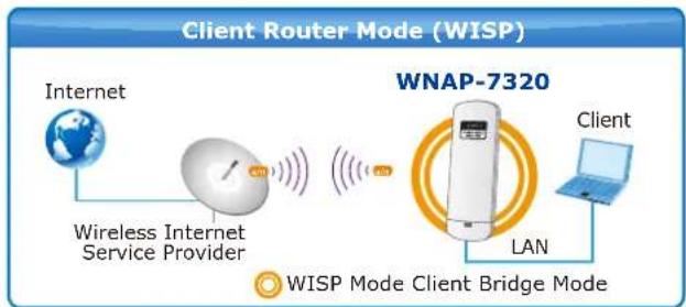
flowchart
graph LR
    A["Internet"] --> B["Wireless Internet Service Provider"]
    B --> C["WNAP-7320"]
    C --> D["Client"]
    C --> E["LAN"]
    E --> F["Client"]
    style A fill:#f9f,stroke:#333
    style B fill:#ccf,stroke:#333
    style C fill:#cfc,stroke:#333
    style D fill:#fcc,stroke:#333
    style E fill:#cff,stroke:#333
    style F fill:#ffc,stroke:#333
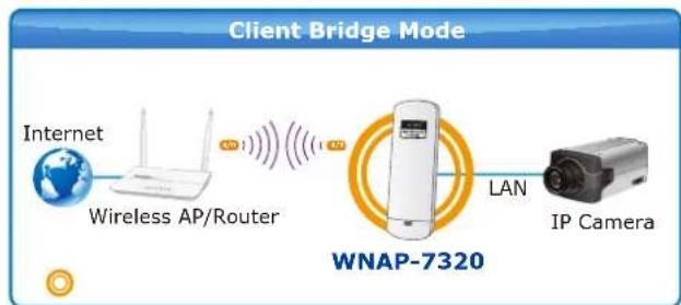
flowchart
graph LR
    A["Internet"] --> B["Wireless AP/Router"]
    B --> C["WiNAP-7320"]
    C --> D["LAN"]
    D --> E["IP Camera"]
Advanced Security and Management
In aspect of security, besides 64/128-bit WEP encryption, the WNAP-7320 integrates WPA / WPA2, WPA-PSK / WPA2-PSK and 802.1x authority to secure and protect your wireless LAN. The wireless MAC filtering and SSID broadcast control consolidate the wireless network security and prevent unauthorized wireless connection. To fulfill enterprise and various applications demand, the WNAP-7320 enhances security and management features such as providing multiple SSID support.
Perfect Solution for Outdoor Environment
The WNAP-7320 is perfectly suitable in outdoor environments and exposed locations. By designing with IP55 and Outdoor UV Stabilized Enclosure, the WNAP-7320 can perform normally under rigorous weather conditions including heavy rain, wind and snow. Moreover, the WNAP-7320 is rated to operate at the temperature from -30 to 75 Degree C; thus it can operate more stably than general outdoor equipments. It is the best way using the WNAP-7320 to build outdoor wireless access applications between buildings on campuses, business, rural areas and etc.
Flexible Deployment with PoE Feature
With the proprietary Power over Ethernet (PoE) design, the WNAP-7320 can be easily applied in the areas where power outlets are not available. It thus reduces the needs of extra cables and dedicated electrical outlets on the wall, ceiling or any other places where are difficult to reach. It enables the wireless LAN deployment becomes more flexible and worries free from the power outlet locations. It is the best way using the WNAP-7320 to build outdoor wireless access applications between buildings on campuses, business, rural areas and etc.
Easy Installation & Management
With user-friendly Web UI and step by step Setup Wizard, the WNAP-7320 is easier to install, even for users who never experience setting up a wireless network. Furthermore, with SNMP-Based management interface, the WNAP-7320 is convenient to be managed and configured remotely.
1.3 Product Features
Industrial Compliant Wireless LAN & LAN
■ Compliant with IEEE 802.11n wireless technology capable of up to 300Mbps data rate
■ Backward compatible with 802.11a standard
■ Equipped with 10/100Mbps RJ-45 Ports for LAN & WAN, Auto MDI/ MDI-X supported
xed-network Broadband AP
■ Supported connection types: Dynamic IP / Static IP / PPPoE / PPTP / L2TP / IPSec
■ Supports Virtual Server, DMZ for various networking applications
■ Supports DHCP Server, UPnP, Dynamic DNS
▶ Interface Characteristics
■ Built-in 14dBi Dual-Polarization Antenna
■ High Output Power up to 500mW with multiple adjustable transmit power control
Outdoor Environmental Characteristics
■ Outdoor UV Stabilized Enclosure, IP55 Protection Grade
■ Passive Power over Ethernet design
■ Operating Temperature: -30\~75 Degree C
Multiple Operation & Wireless Mode
■ Multiple Operation Modes: Bridge, Gateway, WISP
■ Multiple Wireless Modes: AP, Client CPE (WISP), WDS PtP, WDS PtMP, Repeater
■ Supports Dual-SSID allowing users to access different networks through one single AP
■ Supports WMM (Wi-Fi Multimedia)
▶ Secure Network Connection
■ Supports Software Wi-Fi Protected Setup (WPS)
■ Advanced security: 64/128-bit WEP, WPA / WPA2, WPA-PSK / WPA2-PSK (TKIP/AES), and 802.1x Authentication
■ Supports NAT firewall features, with SPI function to protect against DoS attacks
■ Supports IP / Protocol-based access control and MAC Filtering
Easy Installation & Management
■ Web-Based UI and Quick Setup Wizard for easy configuration
■ Remote Management allows configuration from a remote site
■ SNMP-Based management interface
■ System status monitoring includes DHCP Client, System Log
1.4 Product Specification
| Product | WNAP-73205GHz 300Mbps 802.11a/n Wireless Outdoor Access Point | |||
| Hardware Specifications | ||||
| Standard support | IEEE 802.11a/n Wireless LANIEEE 802.11i Wireless SecurityIEEE 802.3 10Base-T EthernetIEEE 802.3u 100Base-TX EthernetIEEE 802.3x Flow Control | |||
| Memory | 32 Mbytes DDR SDRAM8 Mbytes Flash | |||
| Interface | Wireless IEEE802.11a/n, 2T2RLAN: 1 x 10/100Base-TX, Auto-MDI/MDIXWAN: 1 x 10/100Base-TX, Auto-MDI/MDIX | |||
| Antenna | Built-in 14dBi Dual-Polarization Antenna- Horizontal: 45 degree- Vertical: 60 degree | |||
| Wireless RF Specifications | ||||
| Wireless Technology | IEEE 802.11aIEEE 802.11n | |||
| Data Rate | IEEE 802.11a: 54, 48, 36, 24, 18, 12, 9 and 6MbpsIEEE 802.11n (20MHz): up to 150MbpsIEEE 802.11n (40MHz): up to 300Mbp | |||
| Media Access Control CSMA / CA | ||||
| Modulation | Transmission / Emission Type: OFDMData modulation type: OFDM with BPSK, QPSK, 16-QAM, 64-QAM | |||
| Frequency Band 5.180GHz ~ 5.825GHz | ||||
| Operating Channel | 5.180GHz | CH36 | 5.580GHz | CH1 |
| 5.200GHz | CH40 | 5.600GHz | CH1 | |
| 5.220GHz | CH44 | 5.620GHz | CH1 | |
| 5.240GHz | CH48 | 5.640GHz | CH1 | |
| 5.260GHz | CH52 | 5.660GHz | CH1 | |
| 5.280GHz | CH56 | 5.680GHz | CH1 | |
| 5.300GHz | CH60 | 5.700GHz | CH1 | |
| 5.320GHz | CH64 | 5.745GHz | CH1 | |
| 5.500GHz | CH100 | 5.765GHz | CH | |
| 5.520GHz | CH104 | 5.785GHz | CH | |
| 5.540GHz | CH108 | 5.805GHz | CH | |
| 5.560GHz | CH112 | 5.825GHz | CH | |
| *The above 24 channels are defined in theory. The actual application will vary depends on the regulation in different regions and countries. | ||||
| RF Output Power IEEE 802.11a: 27 ± 1dBm | ||||
| IEEE 802.11n: 24 ± 1dBm | |
| Receiver Sensitivity | IEEE 802.11a: -92 ~ -73dBm @ 6Mbps ~ 54MbpsIEEE 802.11n: -94 ~ -73dBm @ MCS0 ~ MCS15 |
| Output Power Control 3~27dBm | |
| Software Features | |
| LAN | Built-in DHCP server supporting static IP address distributing |
| Supports 802.1d STP (Spanning Tree) | |
| WAN | ■ Static IP■ Dynamic IP■ PPPoE■ PPTP■ L2TP■ IPSec |
| Operating Mode | ■ Bridge■ Gateway■ WISP |
| Firewall | NAT firewall with SPI (Stateful Packet Inspection) |
| Built-in NAT server supporting Virtual Server and DMZ | |
| Built-in firewall with Port / IP address / MAC / URL filtering | |
| Wireless Mode | ■ AP■ Client■ WDS PTP■ WDS PTMP■ WDS Repeater (AP+WDS) |
| Channel Width 20MHz / 40MHz | |
| Wireless Isolation | Enable it to isolate each connected wireless clients from communicating with each other mutually. |
| Encryption Type 64/128 | bits WEP, WPA, WPA-PSK, WPA2, WPA2-PSK, 802.1X |
| Wireless Security | Provides wireless LAN ACL (Access Control List) filtering |
| Wireless MAC address filtering | |
| Supports WPS (WIFI Protected Setup) | |
| Enable / Disable SSID Broadcast | |
| Multiple SSID Up to 2 | |
| Max. Wireless Client 40 | |
| Max. WDS AP 8 | |
| Max. Wired Client | 60 |
| WMM Supports Wi-Fi Multimedia | |
| QoS Supports Quality of Service for bandwidth control | |
| NTP Network Time Management | |
| Management | Web UI, DHCP Client, Configuration Backup & Restore, Dynamic DNS, SNMP |
| Diagnostic tool | System Log, Ping Watchdog |
| Mechanical & Power | |
| IP Rate | IP55 |
| Material Outdoor UV Stabilized Enclosure | ||
| Dimension (W x D x H) 275 x 93 x 45mm | ||
| Weight 336 ± 5g | ||
| Installation Pole mounting or Wall mounting | ||
| Power Requirements | LAN 24V DC, 0.5A/ Passive PoEPin 4,5 VDC+Pin 7,8 VDC- | |
| Power Consumption 7.68W | ||
| Environment & Certification | ||
| Operation Temperature | -30~75 Degree C | |
| Operating Humidity 10~95% non-condensing | ||
| Regulatory CE / RoHS | ||
| Accessory | ||
| Standard Accessories | ■ 24V DC Passive PoE injector & Power cord x 1■ Mounting Tie x 2■ Quick Installation Guide x 1■ CD (User's Manual, Quick Installation Guide) x 1 | |
Chapter 2. Hardware Installation
Please follow the instructions below to connect WNAP-7320 to the existing network devices and your computers.
2.1 Hardware Description
■ Dimension: 275 x 93 x 45mm (W x D x H)
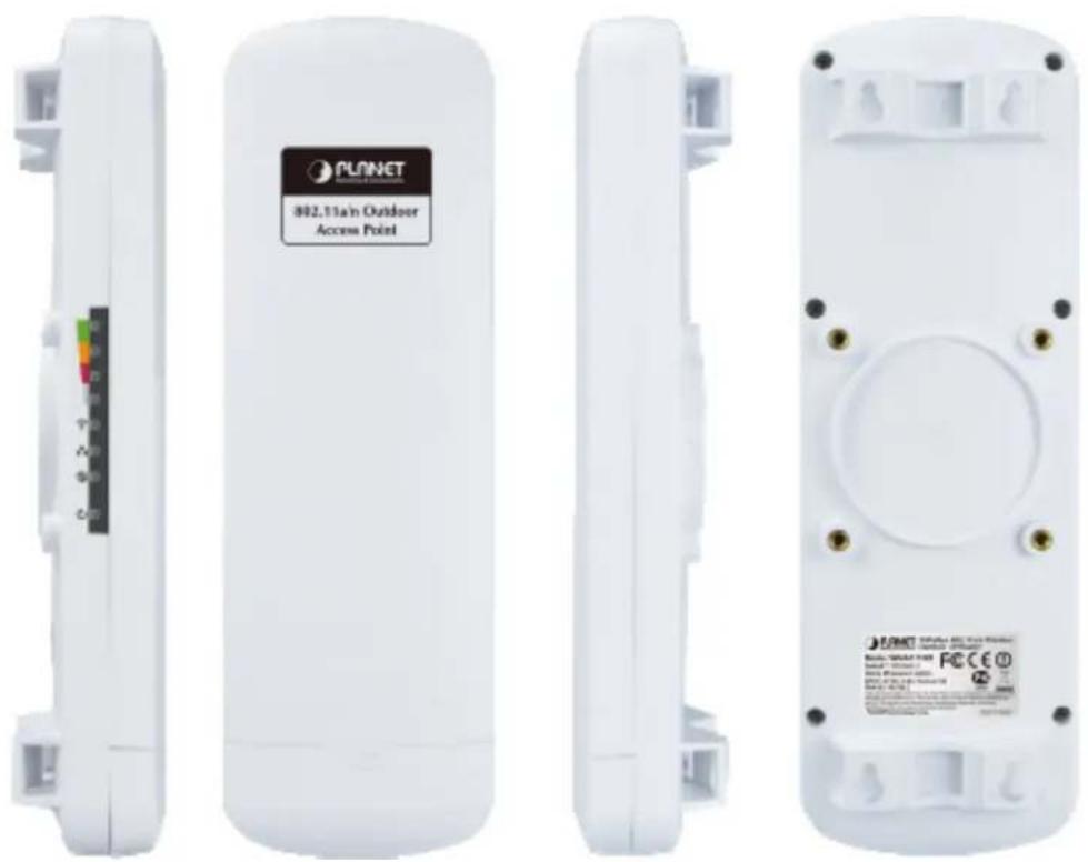
Figure 2-1 Three-way View
2.1.1 The Side Panel – LED
Side Panel - LED
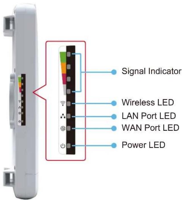
Figure 2-2 LED
LED definition
| LED State Meaning | ||
| Power | On System On | |
| Off System Off | ||
| Signal Indicator | On Indicates the wireless signal strength of remote AP | |
| (Client/Repeater Mode) | Off No remote wireless signal | |
| Wireless | On Wi-Fi On | |
| Off Wi-Fi Off | ||
| WAN Port | On Port linked. | |
| Off No link. | ||
| LAN Port | On Port linked. | |
| Off No link. | ||
Table 2-1 The LED indication
2.1.2 The Rear Panel – Mounting Design
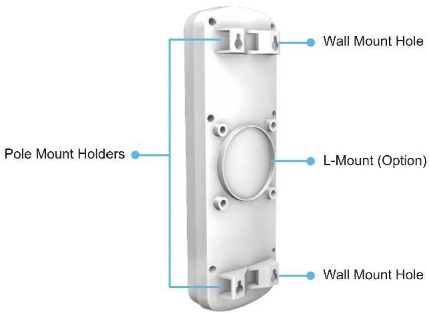
Figure 2-3 Mounting Design
Mounting Design
| LED Meaning | |
| Pole Mount Holders | Use the "Mounting Ties" shipped in the box with the WNAP-7320 for Pole Mounting. |
| L-Mount (Option) | Use the optional "L-Mount Kit" for Pole Mounting with adjustable angle.The L-Mount-Kit must be purchased separately. |
| Wall Mount Hole | Use suitable screws for Wall Mounting. The screws did not supply with the WNAP-7320. |
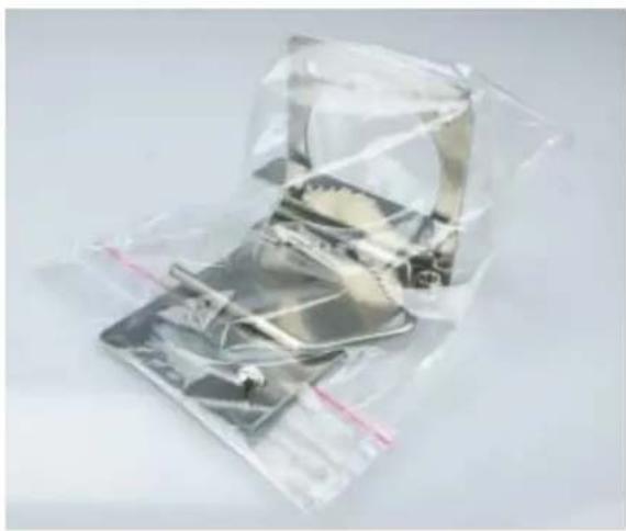
natural_image
Metallic electronic device wrapped in transparent plastic, no visible text or symbolsFigure 2-4 L-Mount Kit
2.1.3 The Bottom Panel – Port
The Bottom panel provides the physical connectors connected to the power adapter and any other network devices. Figure 2-5 shows the Bottom panel of WNAP-7320.
Bottom Panel
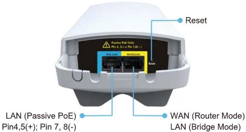
Figure 2-5 Bottom Panel
Interface definition
| Interface Description | |
| LAN (Passive PoE) | 10/100Mbps RJ-45 port , Auto MDI/ MDI-X & Passive PoE supportedConnect LAN port to the PoE injector to power on the device. |
| WAN/LAN | 10/100Mbps RJ-45 port , Auto MDI/ MDI-XConnect this port to the xDSL modem in router mode.Connect this port to the network equipment in bridge mode. |
| Reset | Press Reset button over 5 seconds to return factory default setting. |
Table 2-2 The Interface indication
Chapter 3. Connecting to the AP
3.1 Preparation before Installation
3.1.1 Professional Installation Required
Please seek assistance from a professional installer who is well trained in the RF installation and knowledgeable in the local regulations.
3.1.2 Safety Precautions
- To keep you safe and install the hardware properly, please read and follow these safety precautions.
- If you are installing WNAP-7320 for the first time, for your safety as well as others', please seek assistance from a professional installer who has received safety training on the hazards involved.
- Keep safety as well as performance in mind when selecting your installation site, especially where there are electric power and phone lines.
- When installing WNAP-7320, please note the following things:
♦ Do not use a metal ladder;
♦ Do not work on a wet or windy day;
◆ Wear shoes with rubber soles and heels, rubber gloves, long sleeved shirt or jacket.
- When the system is operational, avoid standing directly in front of it. Strong RF fields are present when the transmitter is on.
3.2 Installation Precautions
■ Users MUST use a proper and well-installed surge arrestor and grounding kit with WNAP-7320; otherwise, a random lightening could easily cause fatal damage to WNAP-7320. EMD (Lightning) DAMAGE IS NOT COVERED UNDER WARRANTY.
- Users MUST use the “Power cord & PoE Injector” shipped in the box with the WNAP-7320. Use of other options will cause damage to the WNAP-7320.

OUTDOOR INSTALLATION WARNING
IMPORTANT SAFETY PRECAUTIONS:
LIVES MAY BE AT RISK! Carefully observe these instructions and any special instructions that are included with the equipment you are installing.
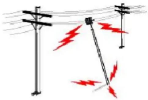
CONTACTING POWER LINES CAN BE LETHAL. Make sure no power lines are anywhere where possible contact can be made. Antennas, masts, towers, guy wires or cables may lean or fall and contact these limes. People may be injured or killed if they are touching or holding any part of equipment when it contacts electric lines. Make sure there is NO possibility that equipment or personnel can come in contact directly or indirectly with power lines.
natural_image
Illustration of three utility poles with red lightning bolts indicating electrical hazard (no text or symbols)Assume all overhead lines are power lines.
The horizontal distance from a tower, mast or antenna to the nearest power line should be at least twice the total length of the mast/antenna combination. This will ensure that the mast will not contact power if it falls either during installation or later.
TO AVOID FALLING, USE SAFE PROCEDURES WHEN WORKING AT HEIGHTS ABOVE GROUND.
- Select equipment locations that will allow safe, simple equipment installation.
- Don't work alone. A friend or co-worker can save your life if an accident happens.
- Use approved non-conducting lasers and other safety equipment. Make sure all equipment is in good repair.
- If a tower or mast begins falling, don't attempt to catch it. Stand back and let it fall.
- If anything such as a wire or mast does come in contact with a power line, DON'T TOUCH IT OR ATTEMPT TO MOVE IT. Instead, save your life by calling the power company.
- Don't attempt to erect antennas or towers on windy days.
MAKE SURE ALL TOWERS AND MASTS ARE SECURELY GROUNDED, AND ELECTRICAL CABLES CONNECTED TO ANTENNAS HAVE LIGHTNING ARRESTORS. This will help prevent fire damage or human injury in case of lightning, static build-up, or short circuit within equipment connected to the antenna.
- The base of the antenna mast or tower must be connected directly to the building protective ground or to one or more approved grounding rods, using 1 OAWG ground wire and corrosion-resistant connectors.
- Refer to the National Electrical Code for grounding details.
IF A PERSON COMES IN CONTACT WITH ELECTRICAL POWER, AND CANNOT MOVE:
- DON'T TOUCH THAT PERSON, OR YOU MAY BE ELECTROCUTED.
- Use a non-conductive dry board, stick or rope to push or drag them so they no longer are in contact with electrical power.
Once they are no longer contacting electrical power, administer CPR if you are certified, and make sure that emergency medical aid has been requested.
3.3 Installing the AP
Please install the AP according to the following steps. Don't forget to pull out the power plug and keep your hands dry.
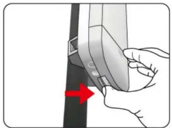
Step 1. Push the latch in the bottom of WNAP-7320 to remove the sliding cover.
natural_image
Illustration of a hand holding a device with a red arrow pointing to a component (no text or symbols present)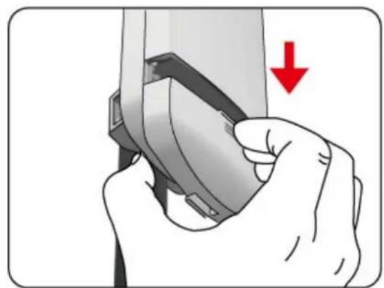
natural_image
Illustration of a hand holding a device with a red downward arrow indicating action (no text or symbols present)Figure 3-1
Step 2. Plug the RJ-45 Ethernet cable into the PoE LAN Port of WNAP-7320.
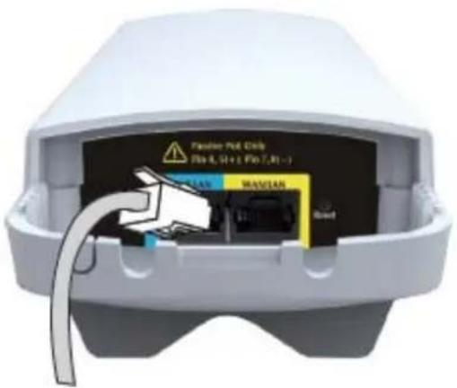
Figure 3-2

Note
RJ-45 8P8C Ethernet cable is required.
Step 3. Take out the power cord and PoE injector, plug the power cord into the DC port and plug the other side of the RJ-45 cable in the Step 2 into the POE port of the PoE injector.
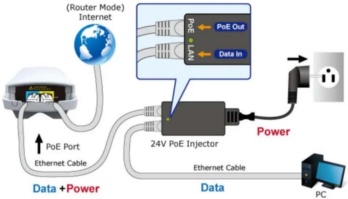
flowchart
graph TD
    A["Router Mode"] -->|PoE Port Ethernet Cable| B["24V PoE Injector"]
    B -->|Data + Power| C["PC"]
    B -->|Data| D["Output"]
    B -->|Power| E["Switch"]
    B --> F["Internet"]
    style A fill:#f9f,stroke:#333
    style B fill:#ccf,stroke:#333
    style C fill:#dfd,stroke:#333
    style D fill:#dfd,stroke:#333
    style E fill:#dfd,stroke:#333
    style F fill:#dfd,stroke:#333
Figure 3-3
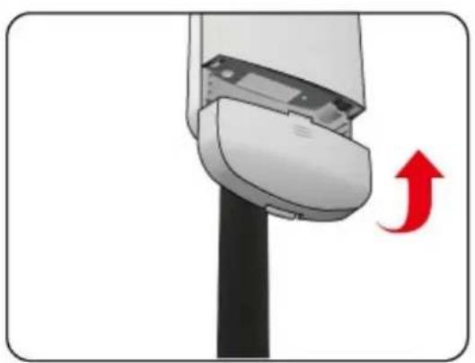
Step 4. Slide the cover back to seal the bottom of the WNAP-7320 to finish the installation.
natural_image
Close-up of a mechanical component with a red upward arrow indicating motion or direction (no text or symbols)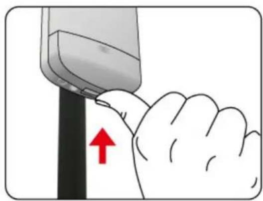
natural_image
Illustration of a hand pressing down on a tool, with a red arrow indicating the process (no text or symbols present)Figure 3-4
3.4 Standard Pole Mounting
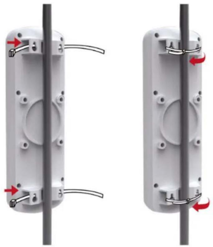
Place the straps through the slots on the back of the WNAP-7320 and then around the pole. Tighten the straps to secure the WNAP-7320.
natural_image
Two identical mechanical components with red arrows indicating rotation, mounted on a vertical pole (no text or symbols present)Figure 3-5 Pole Mounting
3.5 Adjustable Pole Mounting
The WNAP-7320 has L-Mount design in the rear panel which provide flexible mounting option for various environments.
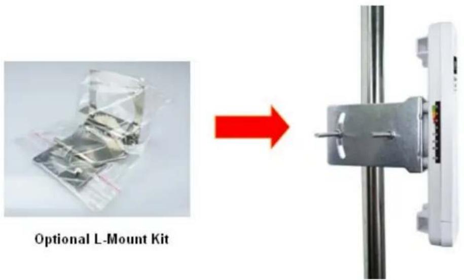
Figure 3-5 L-Mount
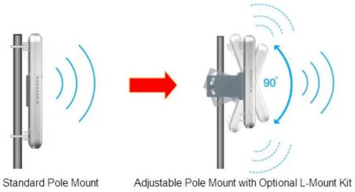
Figure 3-6 L-Mount – Adjustable antenna
3.6 Wall Mounting
There are four Wall Mount Holes in the rear panel of WNAP-7320 which provide wall mounting option for users.
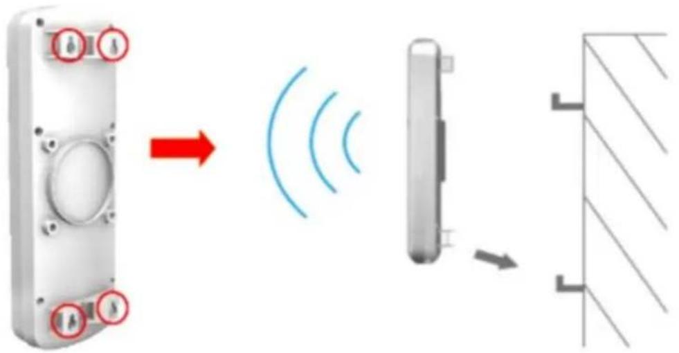
Figure 3-7 Wall Mount
Chapter 4. Quick Installation Guide
This chapter will show you how to configure the basic functions of your Wireless AP using Easy Setup within minutes.

A computer with wired Ethernet connection to the Wireless AP is required for the first-time configuration.
4.1 Manual Network Setup - TCP/IP Configuration
The default IP address of the WNAP-7320 is 192.168.1.1. And the default Subnet Mask is 255.255.255.0. These values can be changed as you desire. In this guide, we use all the default values for description.
Connect the WNAP-7320 with your PC by an Ethernet cable plugging in LAN port of PoE injector in one side and in LAN port of PC in the other side. Please power on the WNAP-7320 by PoE from PoE injector or PoE switch.
In the following sections, we'll introduce how to install and configure the TCP/IP correctly in Windows XP. And the procedures in other operating systems are similar. First, make sure your Ethernet Adapter is working, and refer to the Ethernet adapter's manual if needed.
4.1.1 Configure the IP Address Manually
Summary:
■ Set up the TCP/IP Protocol for your PC.
- Configure the network parameters. The IP address is 192.168.1.xxx ("xxx" is any number from 2 to 254), Subnet Mask is 255.255.255.0, and Gateway is 192.168.1.1 (The AP's default IP address)
1 Select Use the following IP address radio button.
2 If the AP's LAN IP address is 192.168.1.1, enter IP address 192.168.1.x (x is from 2 to 254), and Subnet mask 255.255.255.0.
3 Select Use the following DNS server addresses radio button. In the Preferred DNS Server field, you can enter the DNS server IP address which has been provided by your ISP

Figure 4-1
Now click OK to save your settings.
Now, you can run the Ping command in the command prompt to verify the network connection between your PC and the AP. The following example is in Windows XP OS. Please follow the steps below:
- Click on Start > Run.
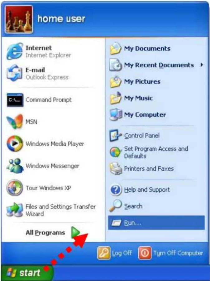
Figure 4-2
- In the run box type "cmd" and click OK. (Windows Vista users type "cmd" in the Start .Search box.) At the prompt.
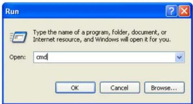
Figure 4-3
Open a command prompt, and type ping 192.168.1.1, and then press Enter.
If the result displayed is similar to Figure 4-4, it means the connection between your PC and the AP has been established well.
![C:\WINDOWS\system32\cmd.exe Microsoft Windows XP [Version 5.1.2600] (C) Copyright 1985-2001 Microsoft Corp. C:\Documents and Settings\user>ping 192.168.1.1 Pinging 192.168.1.1 with 32 bytes of data: Reply from 192.168.1.1: bytes=32 time<1ms TTL=64 Reply from 192.168.1.1: bytes=32 time<1ms TTL=64 Reply from 192.168.1.1: bytes=32 time<1ms TTL=64 Reply from 192.168.1.1: bytes=32 time<1ms TTL=64 Ping statistics for 192.168.1.1: Packets: Sent = 4, Received = 4, Lost = 0 (0% loss), Approximate round trip times in milli-seconds: Minimum = 0ms, Maximum = 0ms, Average = 0ms C:\Documents and Settings\user>](/content/2026/05/964728/images/b5223f9afdf9c2621f5a1cbeb7d7f45ee70cab06ccdb3db7d6c0d893ef18ed5a.jpg)
Figure 4-4 Success result of Ping command
If the result displayed is similar to Figure 4-5, it means the connection between your PC and the AP has failed.
![C:\WINDOWS\system32\cmd.exe Microsoft Windows XP [Version 5.1.2600] (C) Copyright 1985-2001 Microsoft Corp. C:\Documents and Settings\user>ping 192.168.1.1 Pinging 192.168.1.1 with 32 bytes of data: Destination host unreachable. Destination host unreachable. Destination host unreachable. Destination host unreachable. Ping statistics for 192.168.1.1: Packets: Sent = 4, Received = 0, Lost = 4 (100% loss), C:\Documents and Settings\user>](/content/2026/05/964728/images/196692e02ebc5bb66b3b605722001659b0085fdd3d87f8cbfe8bdff76192ba48.jpg)
Figure 4-5 Failure result of Ping command
If the address is 0.0.0.0, check your adapter installation, security settings, and the settings on your AP. Some firewall software programs may block a DHCP request on newly installed adapters.
4.2 Starting Setup in the Web UI
It is easy to configure and manage the WNAP-7320 with the web browser.
Step 1. To access the configuration page, open a web-browser and enter the default IP address http://192.168.1.1 in the web address field of the browser.
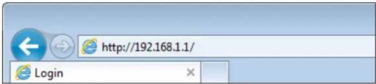
Figure 4-6 Login the AP
After a moment, a login window will appear. Enter admin for the User Name and Password, both in lower case letters. Then click the OK button or press the Enter key.
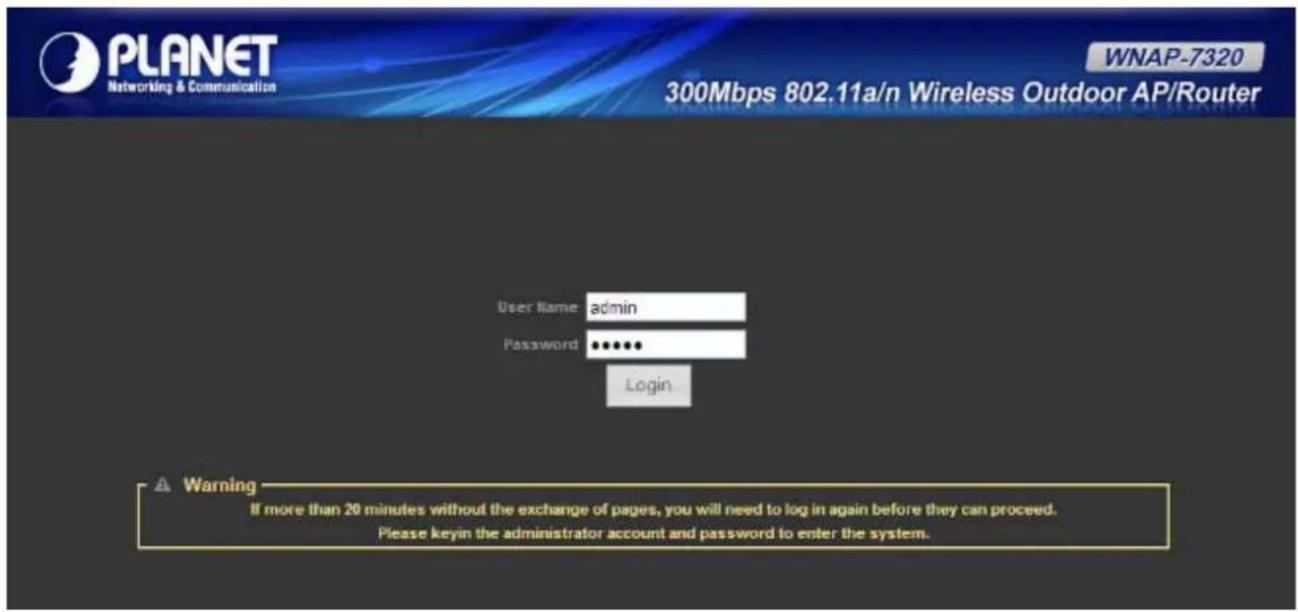
Figure 4-7 Login Window
Default IP Address: 192.168.1.1
Default User name: admin
Default Password: admin

Note
If the above screen does not pop up, it may mean that your web-browser has been set to a proxy. Go to Tools menu>Internet Options>Connections>LAN Settings, in the screen that appears, cancel the Using Proxy checkbox, and click OK to finish it.
After entering the username and password, the Status page screen appears as Figure 4-8
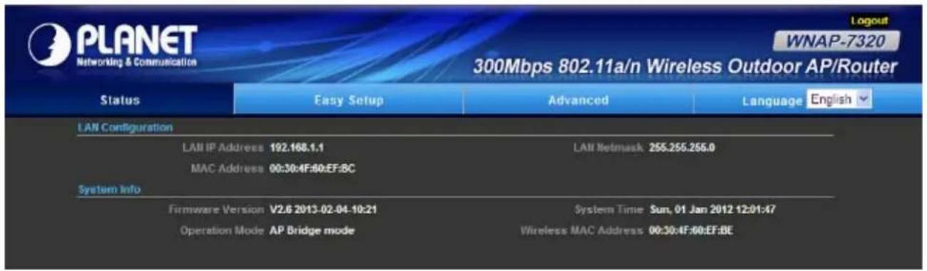
Figure 4-8 WNAP-7320 Web UI Screenshot
Step 2. Go to "Easy Setup" to choose an Operation Mode. Please refer to the instructions in the next chapter for configuring the other Operation Modes.

Figure 4-9 Choose Operation Mode
Step 3. Please enter the SSID, configure your Encryption Settings, Pre-Shared Key and etc. Then click Done button to make the configuration take effect immediately.
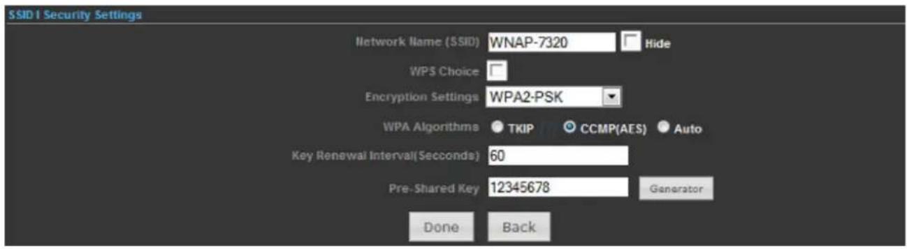
Figure 4-10 Configure Wireless Settings
Chapter 5. Configuring the AP
This chapter delivers a detailed presentation of AP's functionalities and features under 3 main menus (Status, Easy Setup, and Advanced) below, allowing you to manage the AP with ease.

Figure 5-1
5.1 Status
In this page, you can view information about the current running status of WNAP-7320, including WAN interface, LAN interface, Wireless interface, and firmware version information.
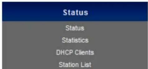
Status
This section allows you to view the AP's System info listed below:
| Internet Configuration | ||
| Connected Type DHCP | Connected Status Disconnected/Connecting... | |
| WAN IP Address | Subnet Mask | |
| Default Gateway | Primary Domain Name Server | |
| Secondary Domain Name Server | MAC Address 00:30:4F:60:37:91 | |
| LAN Configuration | ||
| LAN IP Address 192.168.1.1 | LAN Netmask 255.255.255.0 | |
| MAC Address 00:30:4F:60:37:90 | ||
| System Info | ||
| Firmware Version V2.6 2012-10-23-15:12 | System Time Sun, 01 Jan 2012 12:02:42 | |
| Operation Mode AP Router mode | Wireless MAC Address 00:30:4F:60:37:92 | |
Figure 5-1-1
| Object Description | |
| Internet Configuration | |
| Connected Type | Displays current Internet connection type. |
| Connected Status | Disconnected: Indicates that the Ethernet cable from your ISP side is / is not correctly connected to the WAN port on the AP or the AP is not logically connected to your ISP.Connecting: Indicates that the WAN port is correctly connected and is requesting an IP address from your ISP-connected: Indicates that the AP has been connected to your ISP. |
| WAN IP | Displays WAN IP address. |
| Subnet Mask | Displays WAN subnet mask. |
| Default Gateway | Displays WAN gateway address. |
| Primary Domain Name Server | Displays WAN DNS address. |
| Secondary Domain Name Server | Displays WAN DNS address. |
| MAC Address | Displays AP's WAN MAC address. |
| LAN Configuration | |
| LAN IP Address | Displays LAN IP address. |
| LAN Netmask | Displays LAN subnet mask. |
| MAC Address | Displays AP's LAN MAC address. |
| System Info | |
| Firmware Version | Displays current F/W version. |
| System Time | Displays the System Time. |
| Operation Mode | Displays current Operation Mode. |
| Wireless MAC Address | Displays AP's Wireless MAC address. |
■ Statistics
This section allows you to view the AP's Statistics listed below:
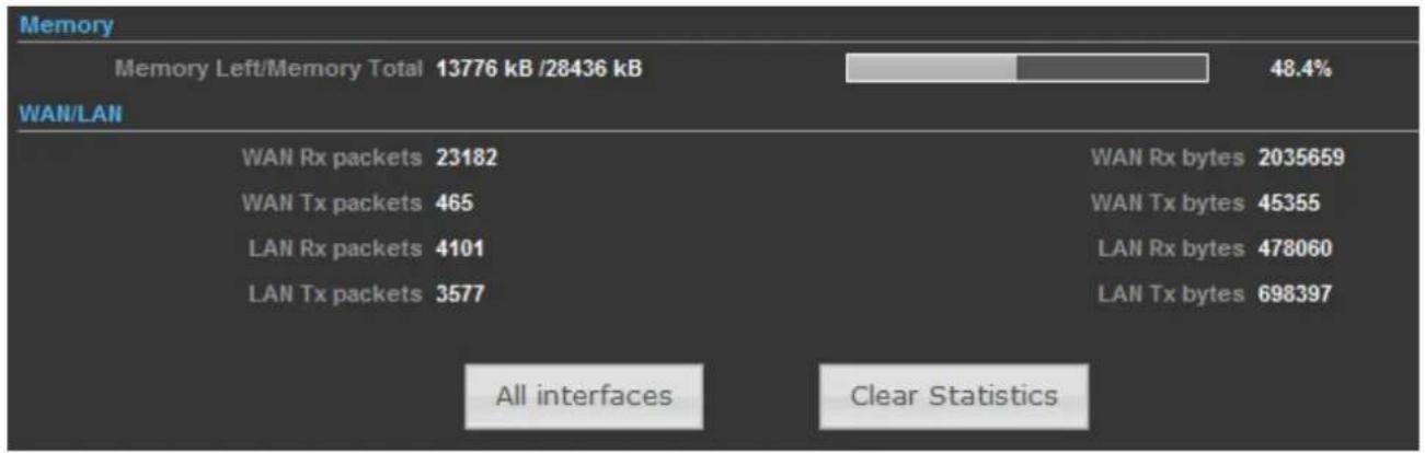
bar
| Metric | Value | | :--- | :--- | | Memory Left/Memory Total | 13776 kB /28436 kB | | WAN/LAN | 48.4% | | WAN Rx packets | 23182 | | WAN Tx packets | 465 | | LAN Rx packets | 4101 | | LAN Tx packets | 3577 | | WAN Rx bytes | 2035659 | | WAN Tx bytes | 45355 | | LAN Rx bytes | 478060 | | LAN Tx bytes | 698397 | All interfaces Clear StatisticsFigure 5-1-2
| Object Description | |
| Memory | |
| • Memory Left/ Memory Total | Displays the retain memory and total memory. |
| WAN/LAN | |
| • WAN Rx packets | Displays the real-time packets received from WAN port. |
| • WAN Rx bytes | Displays the real-time bytes received from WAN port. |
| • WAN Tx packets | Displays the real-time packets transmitted from WAN port. |
| • WAN Tx bytes | Displays the real-time bytes transmitted from WAN port. |
| • LAN Rx packets | Displays the real-time packets received from LAN port. |
| • LAN Rx bytes | Displays the real-time bytes received from LAN port. |
| • LAN Tx packets | Displays the real-time packets transmitted from LAN port. |
| • LAN Tx bytes | Displays the real-time bytes transmitted from LAN port. |
■ DHCP Clients
This section displays a DHCP dynamic client list, which includes MAC address, IP address, and lease time info.
| DHCP Clients | ||
| MAC Address | IP Address | Expires in |
| 00:26:66:46:cb:cf | 192.168.1.195 | 23:27:35 |
| Refresh | ||
Figure 5-1-3
| Object Description | |
| • MAC address | Displays MAC address of a given host. |
| • IP Address | Displays IP address(es) that client(s) obtained from the DHCP server. |
| • Expires in | Remaining time for a corresponding IP address lease. |
■ Station List
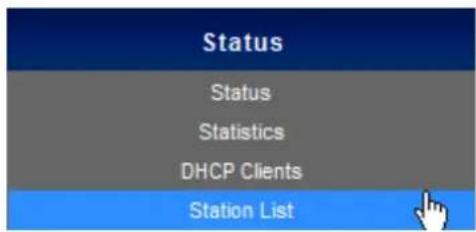
This section allows you to view the Station List. The Station List submenu is only available in AP mode.

Figure 5-1-4
| Object Description | |
| • MAC address | Displays MAC address of a connected client. |
| • Rate | Displays connection speed of a connected client. |
| • Expires in | Displays the signal strength of a connected client. |
5.2 Easy Setup
The Easy Setup helps you configure the basic functions of your Wireless AP within minutes.
Please refer to the Step 2 in the section "4.2 Starting Setup in the Web UI" for the detail procedure.

Figure 5-2-1
5.3 Advanced
"Advanced" includes the following four submenus (Advanced, Firewall Settings, Network Settings, and Wireless Settings). Clicking any of them enters corresponding interface for configuration. Below explains, in details, each such feature.
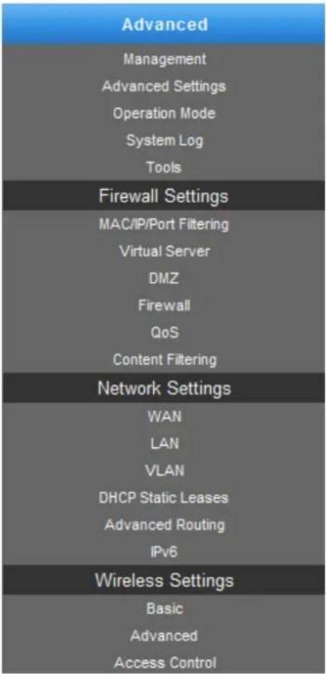
Figure 5-3-1
5.3.1 Advanced - Management
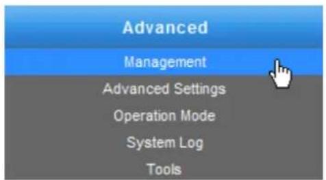
This section allows you to manage the Wireless AP.
5.3.1.1. Web Interface Settings (Password)
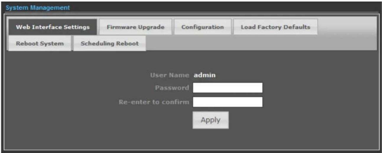
Figure 5-3-2
| Object Description | |
| User Name | Display the User Name info. |
| Password | Enter the new password that you prefer for login. |
| Re-enter to confirm | Re-enter the new password to confirm. |

If you changed the login password, you must enter the new one in the next login.
5.3.1.2. Firmware Upgrade
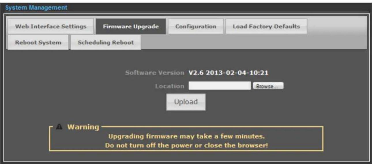
Figure 5-3-3
Click the "Browse..." button to select the new firmware for upgrading.
| Object Description | |
| • Software Version | Display the current Software Version info. |
| • Location | Click the “Browse...” button to select the new firmware in this field. |
| • Upload | Click the “Upload” button to upgrade the new firmware. |

IMPORTANT SAFETY PRECAUTIONS:
Do Not Turn off the power or close the browser during upgrade process!
5.3.1.3. Configuration
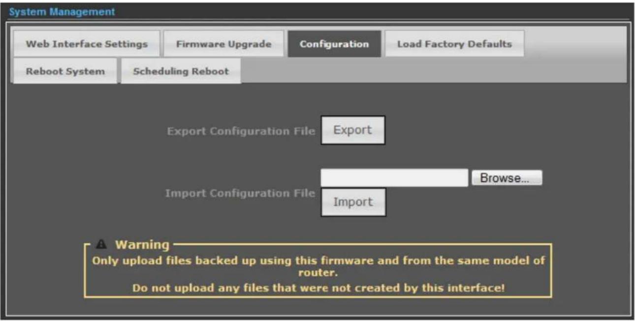
Figure 5-3-4
Click the "Export" button to backup the configuration of the Wireless AP, and click "Import" to restore the configuration.
| Object Description | |
| • Export | Click the “Export” button to backup the configuration. |
| • Browse... | Click the “Browse...” button to select the configuration file in this field for restoring settings. |
| • Import | Click the “Import” button to restore the configuration. |
5.3.1.4. Load Factory Defaults
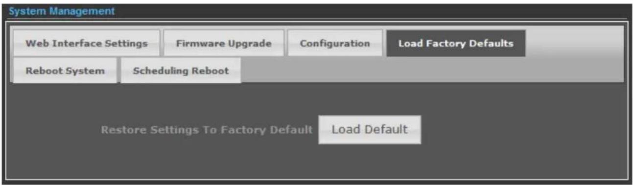
Figure 5-3-5
Click the "Load Default" button to reset it to factory default settings.
Click the "Reboot Now!" button to restart the Wireless AP.
5.3.1.6. Scheduling Reboot
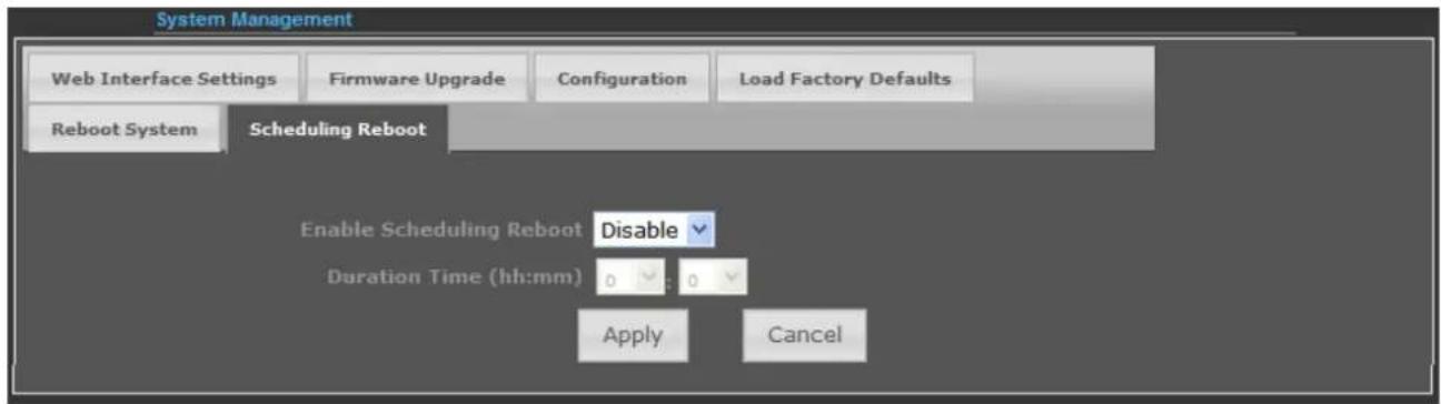
Figure 5-3-7
Select "Enable" to configure the system auto reboot according to the Duration Time (Time interval).
| Object Description | |
| Enable Scheduling Reboot | Enable: select it to enable the Scheduling Reboot.Disable: select it to disable the Scheduling Reboot. |
| Duration Time (hh:mm) | Configure the particular time interval for the system auto reboot.hh: means hoursmm: means minutes |
5.3.2 Advanced – Advanced Settings
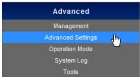
This section allows you to configure advanced settings of the Wireless AP.
5.3.2.1. Time Zone Settings
![Advanced Settings Time Zone Settings DDNS Settings UPNP Settings SNMP Settings Current Time Sun, 01 Jan 2012 14:50; Sync with host Time Zone Please select your Time Zone settings. SNTP Server [?] SNTP synchronization (minutes) Apply Cancel](/content/2026/05/964728/images/7b7ad82b02dd270cf6bcbbefddbb98455c6c0f7ee2ad9654737d97e2beccf41d.jpg)
Figure 5-3-8
The page includes the following fields:
| Object Description | |
| • Current Time | Display the current Time. |
| • Sync with host | Click it to sync your PC's time to the device. |
| • Time Zone | Select your current time zone. |
| • SNTP Server | Configure your SNTP Server. |
| • SNTP Synchronization (minutes) | Determines a time length when device periodically updates its time and date info from Internet. |
5.3.2.2. DDNS Settings
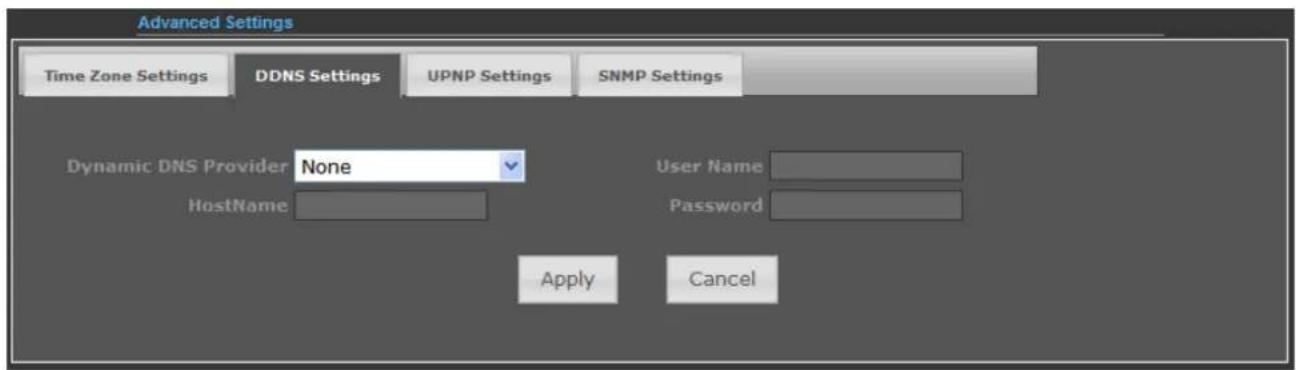
Figure 5-3-9
The page includes the following fields:
| Object Description |
| • Dynamic DNS Provider | Select your Dynamic DNS Provider. |
| • Host Name | Enter the host name or domain name provided by your DDNS service provider. |
| • User Name | Enter the name of your DDNS account. |
| • Password | Password: Enter the password of the DDNS account. |
Example of Planet DDNS Settings:

Please go to http://www.planetddns.com/to register a Planet DDNS account.
Please refer to the FAQ (http://www.planetddns.com/index.php/faq) for how to register a free account.
Please refer to the procedure listed as following to configure using Planet DDNS service.
Step 1. Select "Enable Dynamic DDNS" and "planetddns.com" from the list of Dynamic DNS Provider to use the Planet DDNS service.
Step 2. Configure the DDNS account that has been registered in Planet DDNS website.
Host Name: Enter your DDNS host (format: xxx.planetddns.com, xxx is the registered domain name)
User Name: Enter your DDNS account
Password: Enter your DDNS account's password
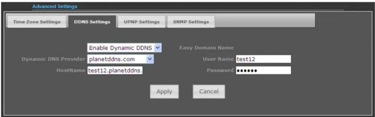
Figure 5-3-10
Step 3. Go to "Advanced-> Firewall Settings-> Firewall" to allow remote access from WAN port.

Figure 5-3-11
Step 4. Go to "Advanced-> Network Settings-> WAN" to configure WAN Connection using Static (Fixed IP).
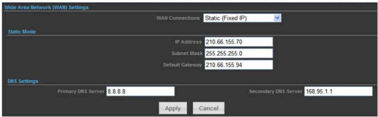
Figure 5-3-12
Step 5. Apply the settings, and connect your WAN port of the Wireless AP to the internet by Ethernet cable.
Step 6. In a remote computer, enter the DDNS host name as the figure shown as below. Then, you should be able to login the WNAP-7320 remotely.
Please remember to enter the remote management port number that you have configured in Step 3.

Figure 5-3-13
You can go to My Devices page of Planet DDNS website to check if the "Last Connection IP" is displayed. This indicates your DDNS service is work properly.
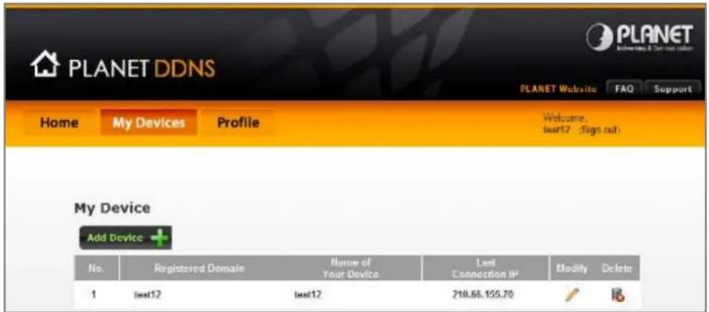
Figure 5-3-14
Example of Easy DDNS Settings:

This service is not required to register any DDNS account.
Please refer to the procedure listed as following to configure using Planet Easy DDNS service.
Step 1. Select "Enable Easy DDNS" to use the Planet Easy DDNS service.
Easy Domain Name: Display the specified domain name for this device. (format: plxxxxxx.planetddns.com, xxxxxx is the last six-digit of the WAN Port MAC address)
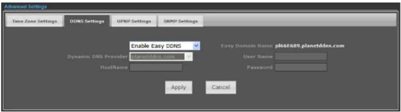
Figure 5-3-15
Step 2. Go to "Advanced-> Firewall Settings-> Firewall" to allow remote access from WAN port.

Figure 5-3-16
Step 3. Go to "Advanced-> Network Settings-> WAN" to configure WAN Connection using Static (Fixed IP).
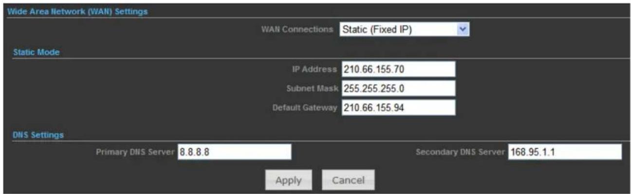
Figure 5-3-17
Step 4. Apply the settings, and connect your WAN port of the Wireless AP to the internet by Ethernet cable.
Step 5. In a remote computer, enter the Easy Domain Name displayed in the Step 1. Then, you should be able to login the WNAP-7320 remotely.
Please remember to enter the remote management port number that you have configured in Step 3.

Figure 5-3-18
5.3.2.3. UPNP Settings
Select "Enable" to enable the UPNP function.
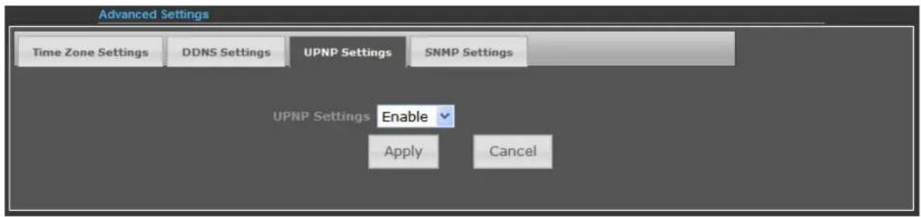
Figure 5-3-19
In the computer connected with WNAP-7320, go to "Network" to check the WNAP-7320 is displayed in the list. Double-click it to logon the Web UI of WNAP-7320.
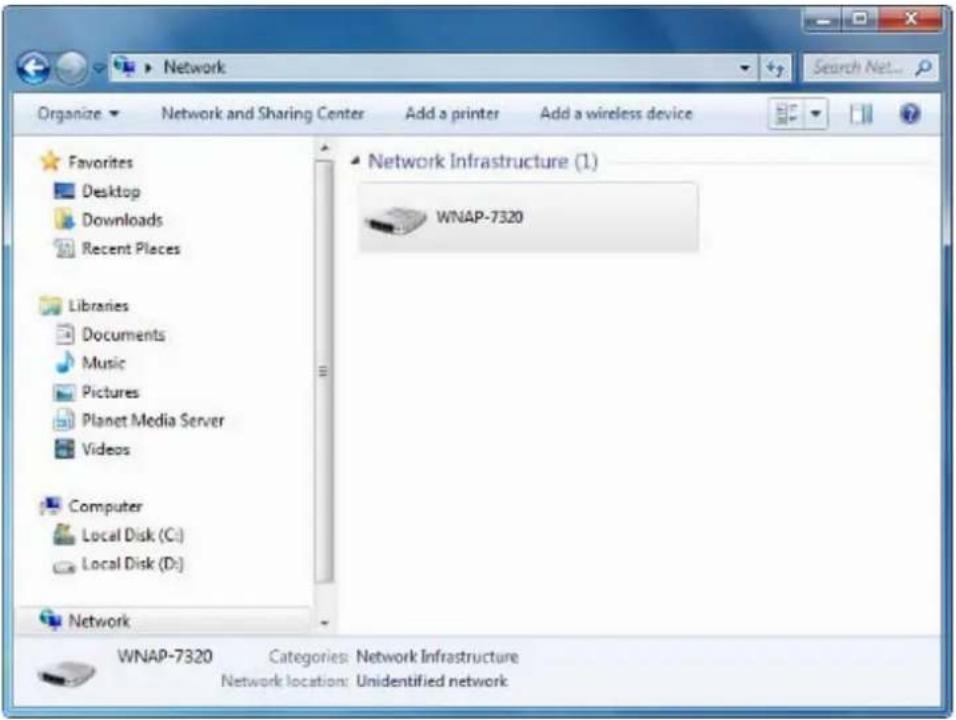
Figure 5-3-20
5.3.2.4. SNMP Settings
Enable SNMP function will allow the network management station to retrieve statistics and status from the SNMP Agent in the device.
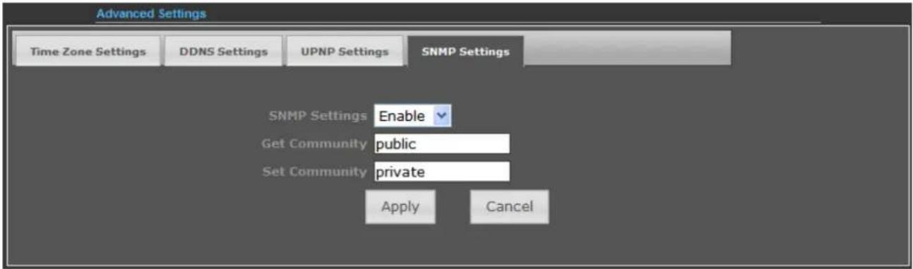
Figure 5-3-21
The page includes the following fields:
| Object Description | |
| • SNMP Settings | Choose Enable to open this function if you want to have remote control through SNMPv1/v2 agent.Choose Disable to close this function. |
| • Get Community | Enter the community name that allows Read-Only access to the Device's SNMP information. The community name can be considered a group password. The default setting is public. |
| • Set Community | Enter the community name that allows Read/Write access to the Device's SNMP information. The community name can be considered a group password. The default setting is private. |
5.3.3 Advanced – Operation Mode
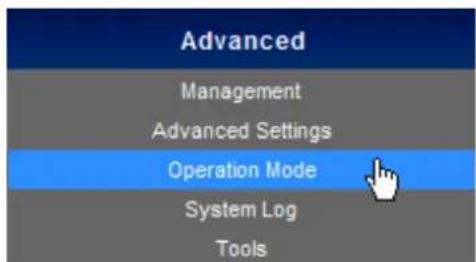
There are 4 operation modes (AP Router, AP Bridge, Client Router, Client Bridge) can be configured to meet various applications.
5.3.3.1. AP Router (AP+Router)
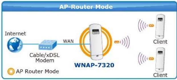
In the Access Point Mode with Router Function, WNAP-7320 acts as central connection point, which wireless clients can connect to. The DHCP & NAT is enabled, so the clients wirelessly connected to WNAP-7320 can share the internet connection by connecting WNAP-7320 to a DSL/Cable modem.
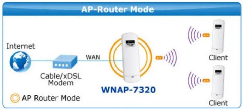
flowchart
graph LR
    A["Internet"] -->|Cable/xDSL Modem| B["WAN"]
    B --> C["WNAP-7320"]
    C --> D["Client"]
    C --> E["Client"]
    style A fill:#f9f,stroke:#333
    style B fill:#ccf,stroke:#333
    style C fill:#cfc,stroke:#333
    style D fill:#fcc,stroke:#333
    style E fill:#fcc,stroke:#333
- Connect the LAN port of WNAP-7320 to the POE port of the PoE Injector with an Ethernet cable.
- Connect the DSL/Cable Modem to the WAN port of the WNAP-7320.
- Plug one end of the power cord into the PoE Injector, and the other end in electrical socket.
- Go to "Advanced->Operation Mode" to configure it to AP Router Mode.

Figure 5-3-22

In this mode, the LAN2 of the WNAP-7320 works as the WAN port.
To configure the Wireless Settings of AP Router Mode, please refer to the section 5.6 Wireless Settings.
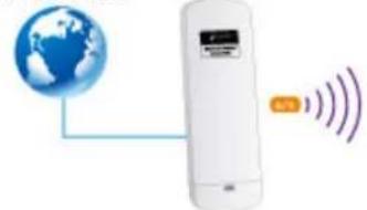
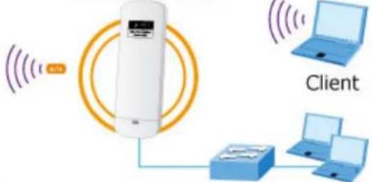
5.3.3.2. AP Bridge (AP+WDS)
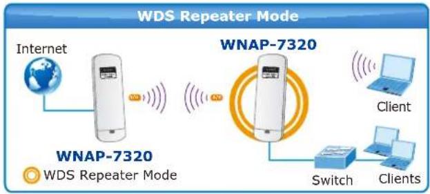
In the Access Point Mode with WDS Function, WNAP-7320 function likes a central connection for any stations or clients. Stations and Client must configure the same SSID and Security Password to associate within the range. WNAP-7320 supports 2 different SSIDs to separate different clients at the same time.
WDS Repeater Mode
Internet
natural_image
White remote control device with a blue globe icon and signal waves (no text or symbols)WNAP-7320

WDS Repeater Mode
WNAP-7320
Switch
Clients
- Connect the LAN port of WNAP-7320 to the POE port of the PoE Injector with an Ethernet cable.
- Connect the PC to the LAN port of the PoE Injector with an Ethernet cable.
- Plug one end of the power cord into the PoE Injector, and the other end in electrical socket.
- Go to "Advanced->Operation Mode" to configure it to AP Bridge Mode.
Operation Mode Configuration

Apply
Cancel
Figure 5-3-23

Note
In this mode, the Wireless interface of the WNAP-7320 works as the WAN port.
To configure the Wireless Settings of AP Bridge Mode, please refer to the section 5.6 Wireless Settings.
5.3.3.3. Client Router (WISP)
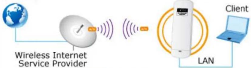
In the Client Router Mode, the WNAP-7320 has DHCP Server build inside that allows many LANs automatically generate an IP address to share the same Internet. Connect an AP/WISP Wirelessly and connect to LANs via wired. Client Router Mode is act completely opposite to the AP Router Mode.
Client Router Mode (WISP)
Internet
flowchart
graph LR
    A["Global"] --> B["Wireless Internet Service Provider"]
    B --> C["LAN"]
    C --> D["Client"]
    style A fill:#f9f,stroke:#333
    style D fill:#bbf,stroke:#333

WISP Mode
- Connect the LAN port of WNAP-7320 to the POE port of the PoE Injector with an Ethernet cable.
- Connect the PC to the LAN port of the PoE Injector with an Ethernet cable.
- Plug one end of the power cord into the PoE Injector, and the other end in electrical socket.
- Go to "Advanced->Operation Mode" to configure it to Client Router Mode.

Figure 5-3-24
WISP Setup Procedure:
Step 1. Go to Advanced-> Wireless Settings-> Profile Settings.

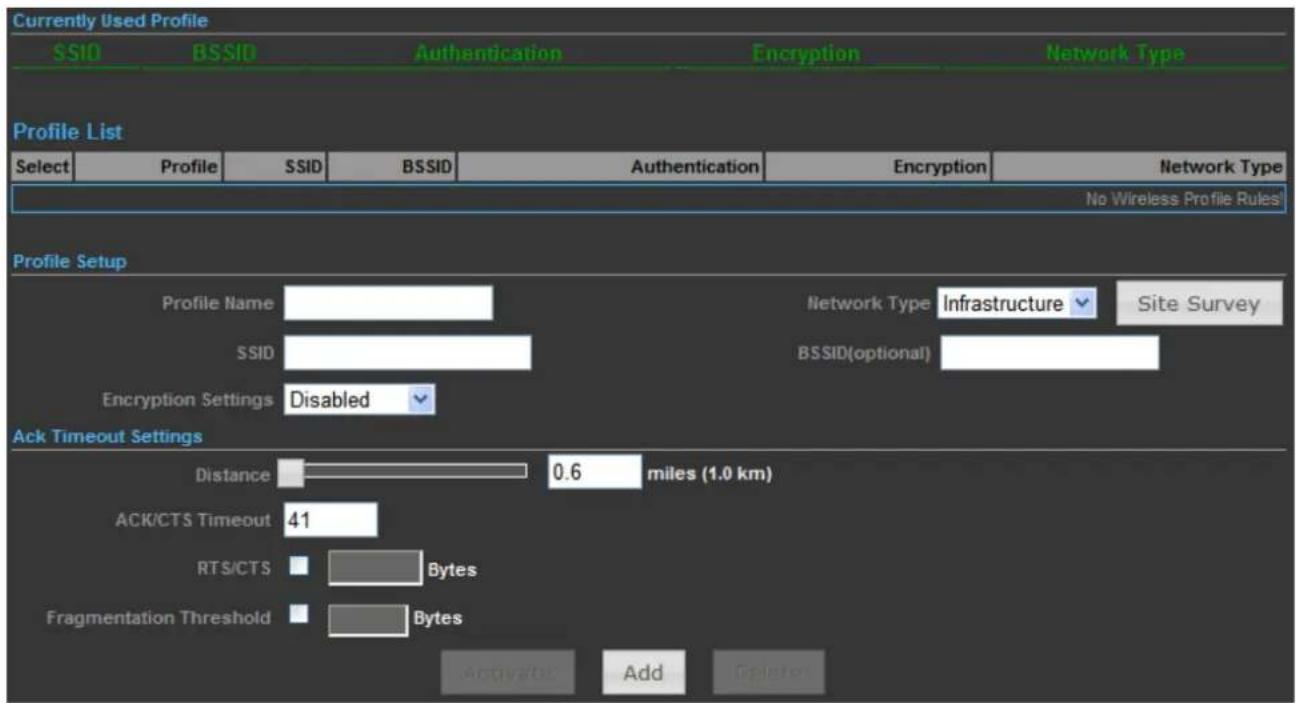
Figure 5-3-25
Step 2. Click "Site Survey" to discover the Wireless Internet Service Provider.
Step 3. Select the WISP's AP, and the click "Select".

Figure 5-3-26
Step 4. Enter the Passphrase, and then click "Add" to add this setting to the profile.
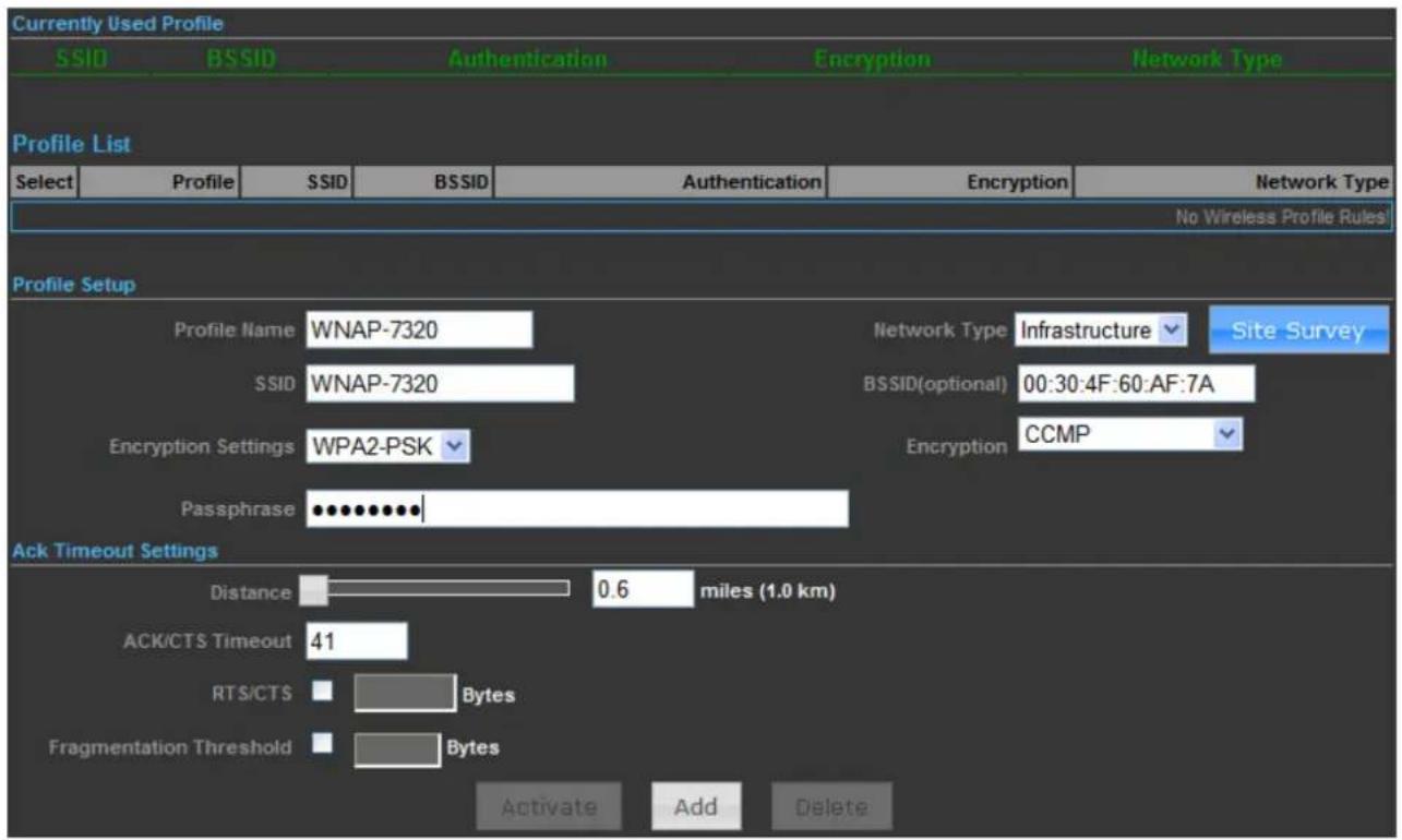
Figure 5-3-27
Step 5. The profile should be listed in the Profile List as the figure shown as below.
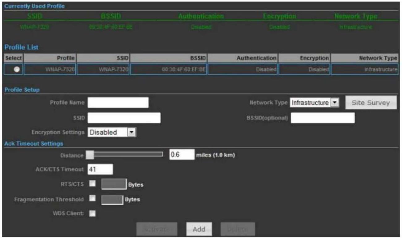
Figure 5-3-28
Step 6. Go to "Advanced->Network Settings->LAN" to enable DHCP Server.
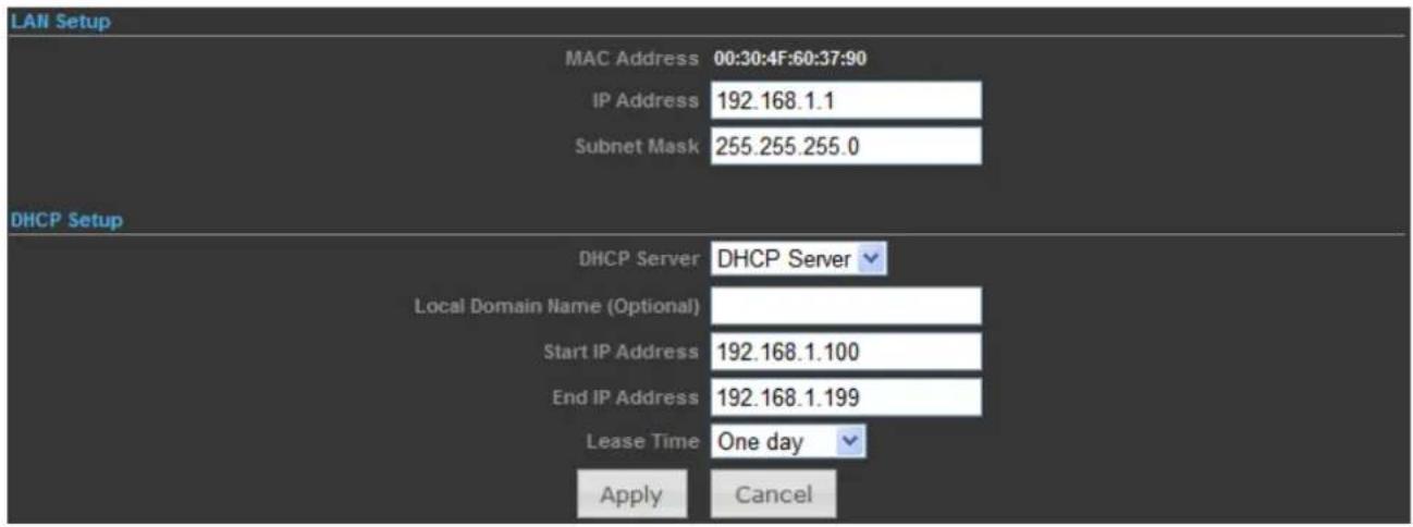
Figure 5-3-29
Step 7. Go to "Advanced-> Network Settings-> WAN" to configure the WAN Connection.
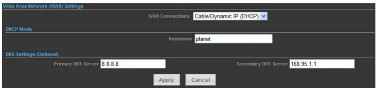
Figure 5-3-30
Step 8. Configure the wired client's TCP/IP setting to "Obtain an IP address automatically".
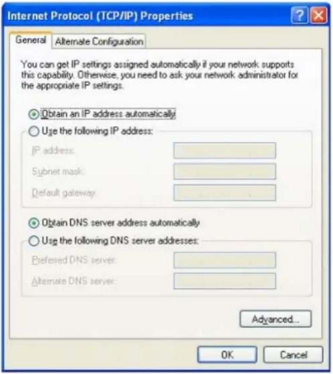
Figure 5-3-31
After got the IP assigned by the WNAP-7320, ping the DNS server to check whether internet connection is reachable.
5.3.3.4. Client Bridge (Slave AP Bridge)
In the Client Bridge Mode, the WNAP-7320 function likes a wireless adapter. Connected to an Access Point wirelessly and surf internet whenever you want. Using Site Survey to scan all the Access Point within the range and configure its SSID and Security Password to associate with it.
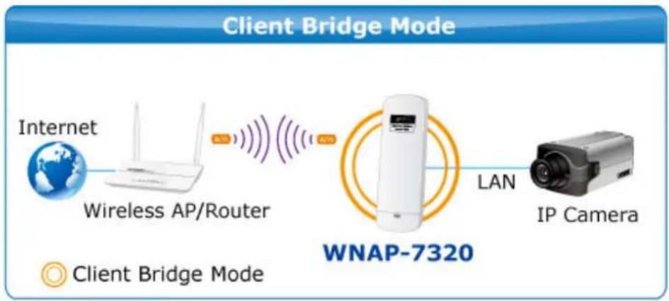
flowchart
graph LR
    A["Internet"] --> B["Wireless AP/Router"]
    B --> C["Wi-Fi Device"]
    C --> D["LAN"]
    D --> E["IP Camera"]
    style A fill:#f9f,stroke:#333
    style B fill:#ccf,stroke:#333
    style C fill:#cfc,stroke:#333
    style D fill:#fcc,stroke:#333
    style E fill:#cff,stroke:#333
- Connect the LAN port of WNAP-7320 to the POE port of the PoE Injector with an Ethernet cable.
- Connect the PC to the LAN port of the PoE Injector with an Ethernet cable.
- Plug one end of the power cord into the PoE Injector, and the other end in electrical socket.
- Go to "Advanced->Operation Mode" to configure it to Client Bridge Mode.

Figure 5-3-32
To configure the Wireless Settings of Client Bridge Mode, please refer to the section 5.6 Wireless Settings.
5.3.4 Advanced - System Log
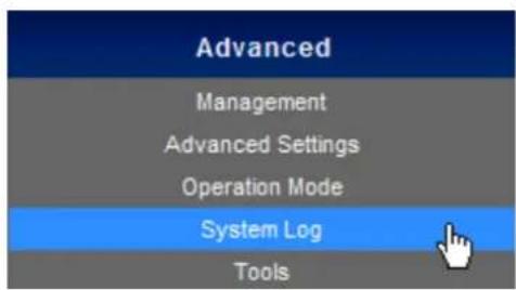
Choose menu "Advanced-> System Log" to view the logs of the Wireless AP.
Click "Refresh" to update the system log.
Click "Clear" to erase the current system log.
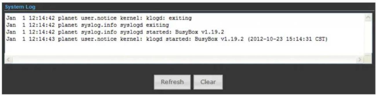
Figure 5-3-33
5.3.5 Advanced - Tools
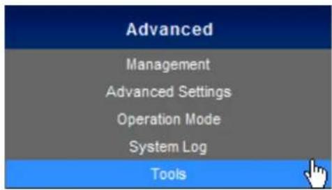
The Tools included Ping, Traceroute, and Throughput can help user diagnostic the network connection.
5.3.5.1. Ping
Ping is a network tool used to test whether a particular host is reachable across an IP network.
Enter the IP, Ping Count, and click "Start" to diagnostic your internet connection.
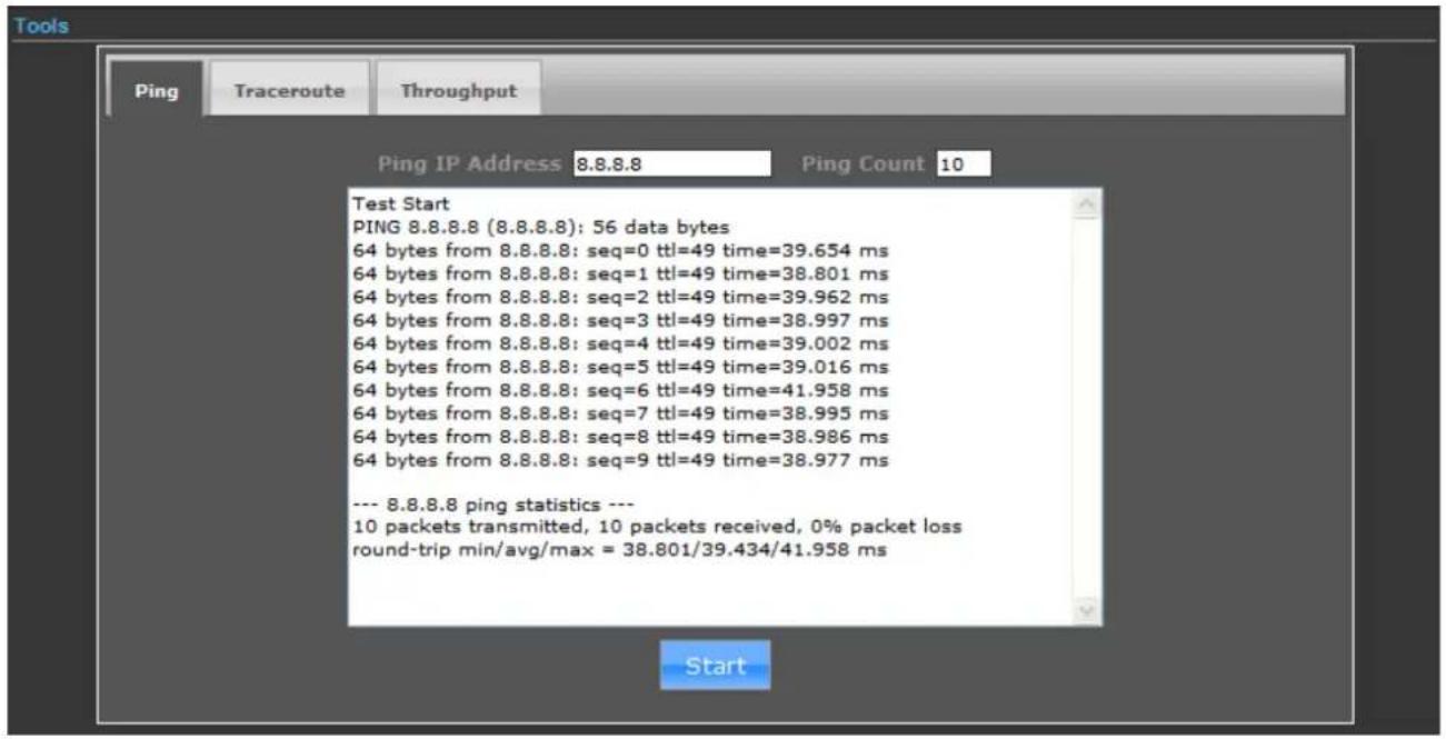
Figure 5-3-34
5.3.5.2. Traceroute
Traceroute is a computer network diagnostic tool for displaying the route (path) and measuring transit delays of packets across an Internet Protocol (IP) network. It can help identify connection problems.
Enter the IP or Hostname, and click "Start" to diagnostic your internet connection.
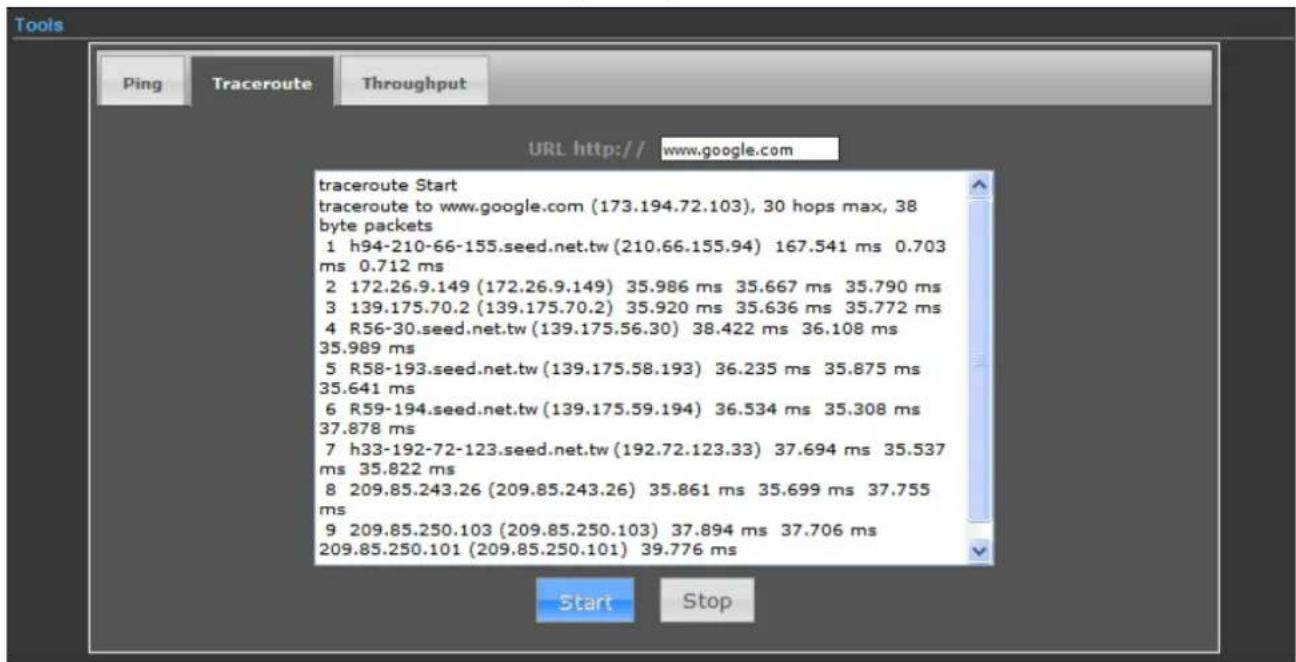
Figure 5-3-35
5.3.5.3. Throughput
Click "VISIT THE SITE TO TEST SPEED" button to go http://www.speedtest.net/ to test the internet connection speed.

Figure 5-3-36
5.4 Firewall Settings
5.4.1 MAC/IP/Port Filtering
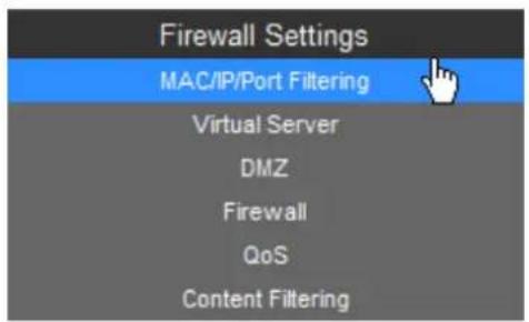
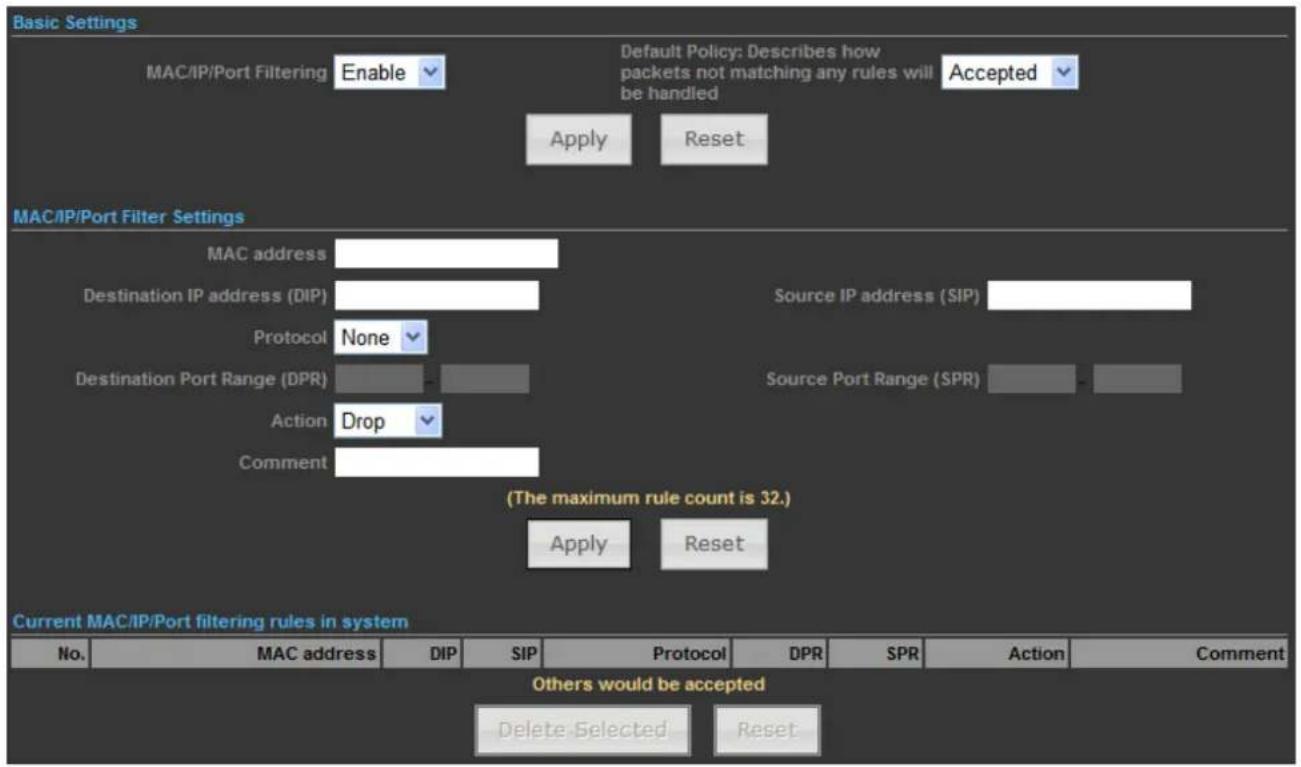
Figure 5-4-1
The page includes the following fields:
| Object Description | |
| • MAC/IP/Port Filtering | Select Enable to enable the MAC/IP/Port Filtering function. |
| • Default Policy | Select a policy for filtering rule. |
| • MAC Address | Fill in the MAC address of source NIC, to restrict data transmission. |
| • Destination IP address (DIP) | Fill in the IP address of destination, to restrict data transmission. |
| • Source IP address (SIP) | Fill in the IP address of source, to restrict data transmission. |
| • Protocol | Select the protocol that you want to restrict. There are four options: None, TCP, UDP and ICMP. |
| • Destination Port Range | Fill in the start-port and end-port number of destination, to restrict data transmission. |
| • Source Port Range | Fill in the start-port and end-port number of source, to restrict data transmission. |
| • Action | Select Accept or Drop to specify the action of filtering policies. |
| • Comment | Make a comment for the filtering policy. |
5.4.2 Virtual Server
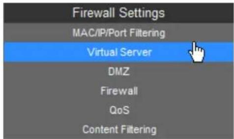
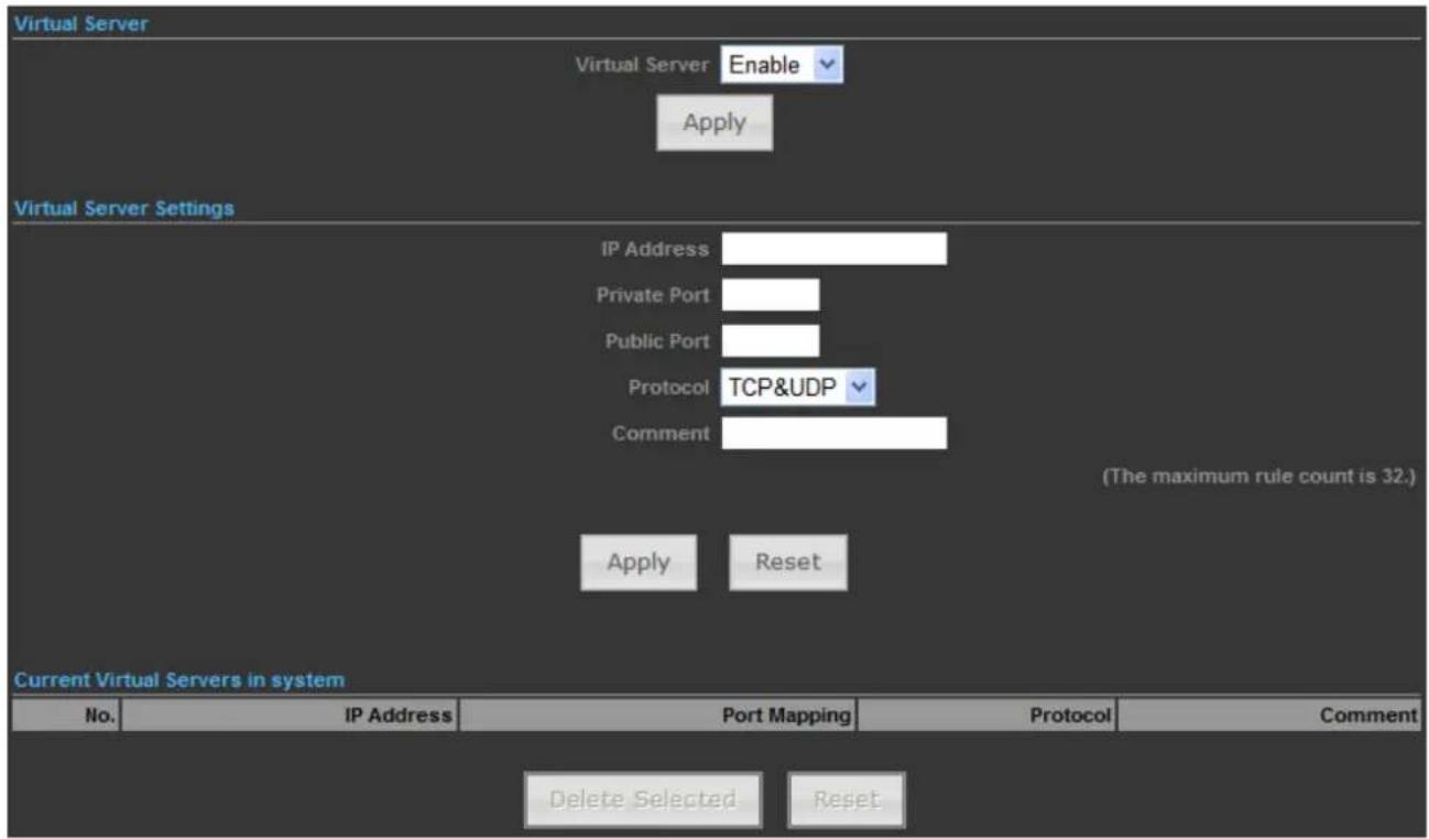
Figure 5-4-2
The page includes the following fields:
| Object Description | |
| • Virtual Server | Select Enable to enable the Virtual Server function. |
| • IP address | To forward data packets coming from WAN to a specific IP address that hosted in local network behind the NAT firewall, fill in the IP address. |
| • Private Port | To forward data packets coming from WAN to a specific IP address that hosted in local network behind the NAT firewall, fill in the private port. |
| • Public Port | To forward data packets coming from WAN to a specific IP address that hosted in local network behind the NAT firewall, fill in the public port. |
| Protocol | The protocol used for this application, either of TCP, UDP, or TCP&UDP (all protocols are supported by the Device.). |
| Comment | Make a comment to help identify the setting. |
5.4.3 DMZ
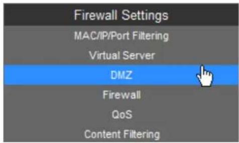

Figure 5-4-3
The page includes the following fields:
| Object Description | |
| • DMZ Settings | Select Enable to enable the DMZ function. |
| • DMZ IP Address | To support DMZ in your firewall design, fill in the IP address of DMZ host that can be access from the WAN interface. |
5.4.4 Firewall
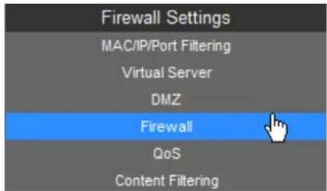
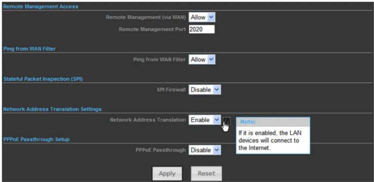
Figure 5-4-4
The page includes the following fields:
| Object Description | |
| • Remote Management (via WAN) | Select Deny or Allow for remote management function. |
| • Remote Management Port | Configure the port for remote management. |
| • Ping from WAN Filter | Select Deny or Allow for Ping permit from WAN. |
| • SPI Firewall | Select Disable or Enable for SPI firewall function. |
| • Network Address Translation | Enable it to let the LAN devices connect to the internet.All computers must be assigned with a public IP address to get connected to the Internet without NAT. However, Internet Service Providers only provide very few IP addresses to every user. Therefore it is necessary to use NAT to share a single public IP address to multiple computers on local network, so everyone can get connected to the Internet. |
| • PPPoE Passthrough | Enable it to allow Multiple PPP connections on remote hosts. |
5.4.5 QoS
Quality of Service provides an efficient way for clients on the network to share the bandwidth with a promised quality of Internet service. Without QoS, all computers and devices on the network will compete with each other to get the bandwidth, and some applications which require guaranteed bandwidth (like video streaming and network telephone) will be affected. With this function, you can limit the maximum bandwidth or give a guaranteed bandwidth for a specific computer, to avoid such unpleasing result from happening.
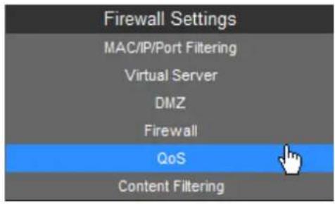
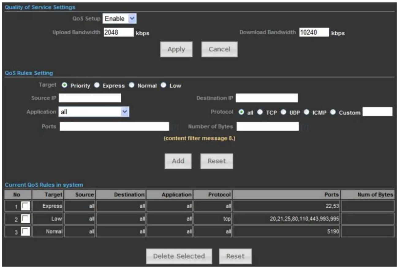
Figure 5-4-5
The page includes the following fields:
| Object Description | |
| • QoS Setup | Select Enable to enable the QoS function. |
| • Upload Bandwidth | Set the limit of total upload bandwidth in kbits. To disable upload bandwidth limitation, input ‘0’ here. |
| • Download Bandwidth | Set the limit of total download bandwidth in kbits. To disable download bandwidth limitation, input ‘0’ here. |
| • Target | Set the target of QoS rule. |
| • Source IP | Specify the local (source) IP address that will be affected by this rule. Please input the starting IP address in the left field, and input the end IP address in the right field to define a range of IP addresses, or just input the IP address in the left field to define a single IP address. |
| • Destination IP | Specify the remote (destination) IP address that will be affected by this rule. Please input the starting IP address in the left field, and input the end IP address in the right field to define a range of IP addresses, or just input the IP address in the left field to define a single IP address. |
| • Application | Select the pre-defined application for this rule. |
| • Protocol | Please select the protocol type of this rule. If you don’t know what protocol your application uses, please try ‘TCP’ first, and switch to ‘UDP’ if this rule doesn’t seems to work. |
| • Ports | Fill out the ports for this rule. |
| • Number of Bytes | Fill out the max. Number of bytes for this rule. |
5.4.6 Content Filtering
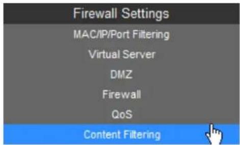
There are two types (Webs URL Filter Settings and Web Host Filter Settings) of content filtering.
5.4.6.1. Webs URL Filter Settings
The Webs URL Filter option allows you to set up a list of Web sites you would like to deny through your network. Please enter a URL for filtering.
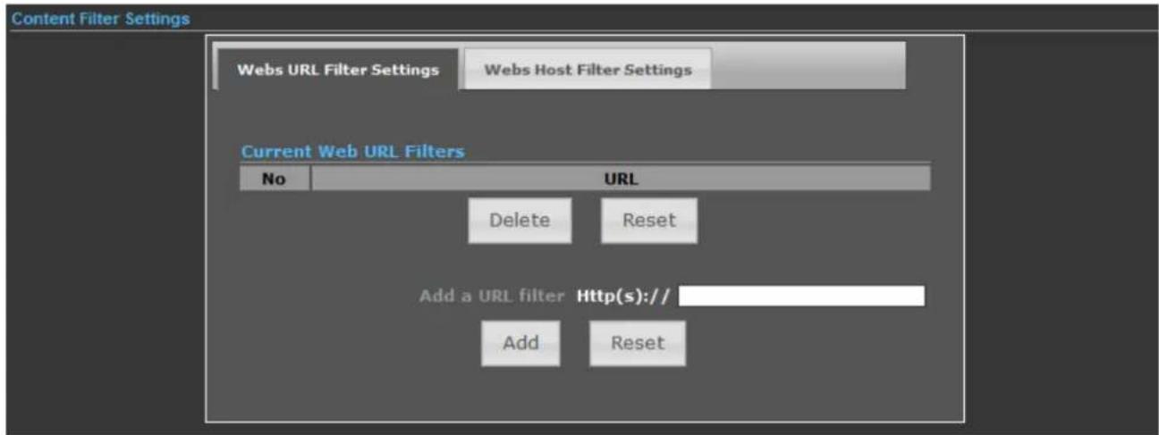
Figure 5-4-6
5.4.6.2. Web Host Filter Settings
The Webs Host Filter option allows you to set up a list of keyword you would like to deny through your network. Please enter a Host (keyword) for filtering.
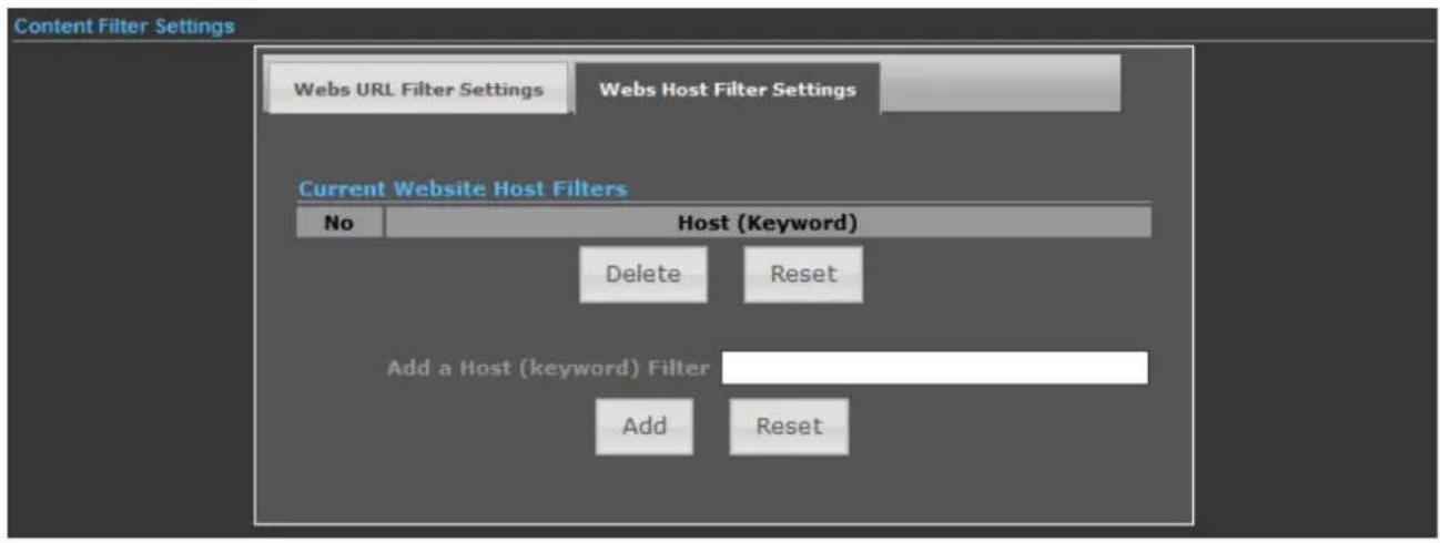
Figure 5-4-7
5.5 Network Settings
5.5.1 WAN
There are 5 submenus under the Network menu: WAN, LAN, VLAN, Advanced Routing and IPv6. Click any of them, and you will be able to configure the corresponding function.
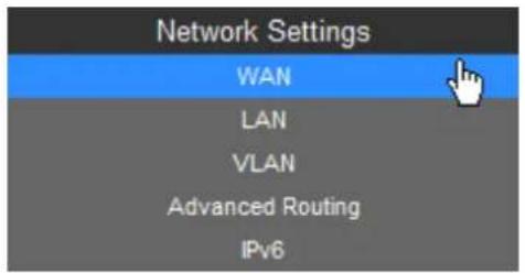
WAN Connection Types:
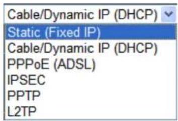
5.5.1.1. Static (Fixed IP)
If your ISP provides a static or fixed IP Address, Subnet Mask, Gateway and DNS setting, select Static (Fixed IP). The Static IP settings page will appear as the figure shown as below.
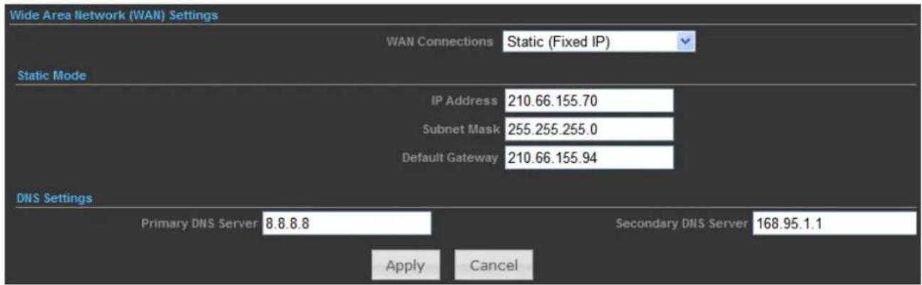
Figure 5-5-1
The page includes the following fields:
| Object Description | |
| • WAN Connections | Select Static (Fixed IP) from the list. |
| • IP Address | Enter the IP address in dotted-decimal notation provided by your ISP. |
| • Subnet Mask | Enter the subnet Mask in dotted-decimal notation provided by your ISP, usually is 255.255.255.0 |
| • Default Gateway | (Optional) Enter the gateway IP address in dotted-decimal notation provided by your ISP. |
| • Primary DNS Server | (Optional) Enter the DNS IP address in dotted-decimal notation provided by your ISP. |
| • Secondary DNS Server | (Optional) Enter another DNS IP address in dotted-decimal notation provided by your ISP. |
5.5.1.2. Cable/Dynamic IP (DHCP)
If your ISP provides the DHCP service, please choose Cable/Dynamic IP (DHCP) type, and the AP Router will automatically obtain IP parameters from your ISP. You can see the page shown as the below.
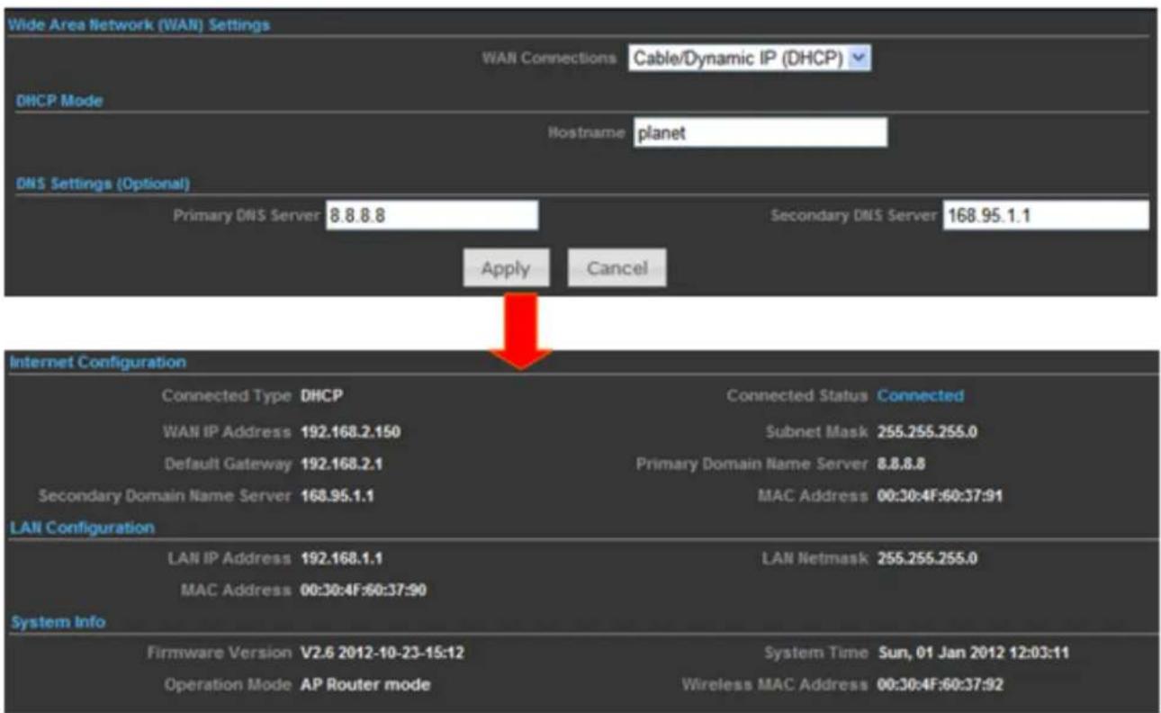
Figure 5-5-2
The page includes the following fields:
| Object Description | |
| • WAN Connections | Select Cable/Dynamic IP (DHCP) from the list. |
| • Host Name | This option specifies the Host Name of the AP Router. |
| • Primary DNS Server | (Optional) Enter the DNS IP address in dotted-decimal notation provided by your ISP. |
| • Secondary DNS Server | (Optional) Enter another DNS IP address in dotted-decimal notation provided by your ISP. |
5.5.1.3. PPPoE (ADSL)
If local ISP provides a PPPoE connection, choose PPPoE (ADSL) and fill the necessary parameters below.
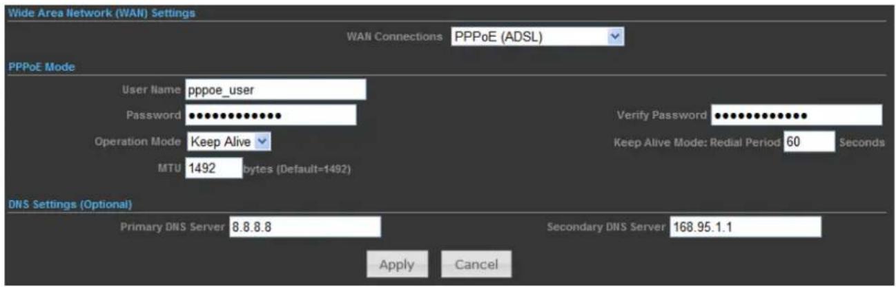
Figure 5-5-3
The page includes the following fields:
| Object Description | |
| WAN Connections | Select PPPoE (ADSL) from the list. |
| Host Name | This option specifies the Host Name of the AP Router. |
| User Name / Password | Enter the User Name and Password provided by your ISP. These fields are case-sensitive. |
| Verify Password | Enter the same password entered above for the confirmation. |
| Operation Mode | Keep Alive: Being constantly connected. |
| Keep Alive Mode | Set up the redial period after the disconnection.The default setting is "60 seconds". |
| MTU | Please input the MTU value of your network connection here. If you don't know, please keep the default value. |
| Primary DNS Server | (Optional) Enter the DNS IP address in dotted-decimal notation provided by your ISP. |
| Secondary DNS Server | (Optional) Enter another DNS IP address in dotted-decimal notation provided by your ISP. |
5.5.1.4. IPSEC
If your ISP provides IPSEC connection, please select IPSEC. And enter the following parameters.
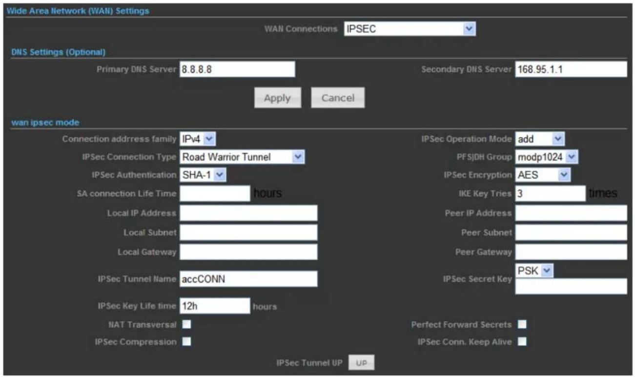
Figure 5-5-4
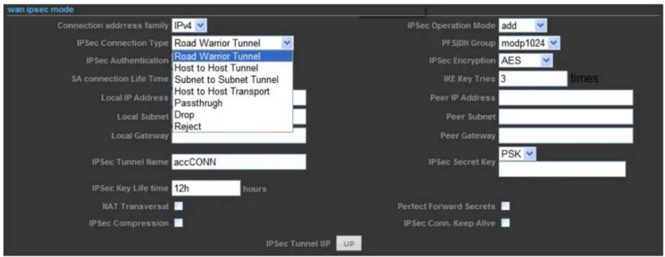
Figure 5-5-5
The page includes the following fields:
| Object Description | ||
| • WAN Connections | Select IPSEC from the list. | |
| • Primary DNS Server | (Optional) Enter the DNS IP address in dotted-decimal notation provided by your ISP. | |
| • Secondary DNS Server | (Optional) Enter another DNS IP address in dotted-decimal notation provided by your ISP. | |
| • Connection address family | For an IPSec connection, all host addresses must be of the same Address Family (IPv4 and IPv6 use different Address Families). | |
| • IPSec Operation Mode | Select the IPSec Operation Mode from the drop-down list. | |
| • IPSec Connection Type | This field allows you to set the connection type to any of the following:SelectTunnelto specify a Host to Host, Host to Subnet (Road Warrior), orSubnet to Subnet Tunnel. This is by far the most common connection type.SelectTransportto specify a Host to Host Transportmode tunnel. This connection type is much less common, and would generally only be used if you are attempting to establish and IPSec connection to another host which specifically requires this mode.SelectPassthroughto disable IPSec processing on packets associated with the tunnel. We can't imagine a scenario where you would use this connection type. I mean seriously, if you don't allow IPSec to process the packets then you don't really have a tunnel, right? Still, the underlying protocol supports this mode, and so here we are.SelectDropto cause the kernel to drop IPSec packets associated with the tunnel.SelectRejectto cause the kernel to reject IPSec packets associated with the tunnel. | |
| • PFS|DH Group | Perfect Forward Secrecy (PFS)—PFSensures that a given IPSec SA key was not derived from any other secret, like some other keys. In other words, if someone breaks a key, PFS ensures that the attacker is not able to derive any other key. If PFS is not enabled, someone can potentially break the IKE SA secret key, copy all the IPSec protected data, and then use knowledge of the IKE SA secret in order to compromise the IPSec SAs setup by this IKE SA. With PFS, breaking IKE does not give an attacker immediate access to IPSec. The attacker needs to break each IPSec SA individually.Diffie-Hellman (DH) key exchange protocol allows two parties without any initial shared secret to create one securely. The following Modular Exponential (MODP) and Elliptic Curve (EC2N) Diffie-Hellman (also known as "Oakley") Groups are supported: | |
| Diffie-Hellman Group Name Reference | ||
| Group 1 768 bit MODP group RFC 2409 | ||
| Group 2 1024 bits MODP group RFC 2409 | ||
| Group 3 EC2N group on GP(2^155) RFC 2409 | ||
| Group 4 EC2N group on GP(2^185) RFC 2409 | ||
| Group 5 1536 bits MODP group RFC 3526 | ||
| • IPSec Authentication | The AP supports SHA1 & MD5 authentication algorithms. | |
| • IPSec Encryption | The AP supports DES, 3DES, AES, Blowfish, Twofish, Camellia Encryption methods.DES - 56-bit DES-CBC encryption algorithm3DES - 168-bit DES encryption algorithmAES - 128, 192 and 256-bit key AES-CBC encryption algorithmBlowfish - a symmetric block cipher that can be used as a drop-in replacement for DES or IDEA. It takes a variable-length key, from 32 bits to 448 bits.Twofish - Twofish has a 128-bit block size, a key size ranging from 128 to 256 bits, and is optimized for 32-bit CPUs.Camellia - 128, 192 and 256-bit key Camellia encryption algorithm | |
| • SA connection Life Time | This value describes the timeframe in hours for which the IKE SA is valid and when the next rekeying should take place. | |
| • IKE Key Tries | The field is used to specify the retry times of IKE Key. | |
| • Local IP Address | This field is used to configure the IP address of the Untangle server on the network configured in the Local Network field. | |
| • Peer IP Address | This field should contain the public IP address of the host to which the IPSec VPN will be connected. | |
| • Local Subnet | This field is used to configure the local network that will be reachable from hosts on the other side of the IPSec VPN. | |
| • Peer Subnet | This field is used to configure the remote network that will be reachable from hosts on the local side of the IPSec VPN. | |
| • Local Gateway | This field is used to configure the Gateway of the Untangle server on the network configured in the Local Network field. | |
| • Peer Gateway | This field should contain the public Gateway of the host to which the IPSec VPN will be connected. | |
| • IPSec Tunnel Name | This field should contain a short name or description. | |
| • IPSec Secret Key | This field should contain the shared secret or PSK (pre-shared key) that is used to authenticate the connection, and must be the same on both sides of the tunnel for the connection to be successful. Because the PSK is actually used as the encryption key for the session, using long strings of a random nature will provide the highest level of security. | |
| IPSec Key Life time | Lifetime settings determine when a new key is generated. Any time a key lifetime is reached, the associated SA is also renegotiated. The process of generating new keys at intervals is called dynamic rekeying or key regeneration. Lifetimes allow you to force the generation of a new key after a specific interval. For example, if the communication takes 12 hours and you specify the key lifetime as 1 hour, 12 keys will be generated (one every 1 hour) during the exchange. | |
| NAT Traversal | NAT Traversal also known as UDP encapsulation allows traffic to get to the specified destination when a device does not have a public address. This is usually the case if your ISP is doing NAT, or the external interface of your firewall is connected to a device that has NAT enabled. | |
| Perfect Forward Secrets | Select the checkbox to enable PFS (Perfect Forward Secrets). | |
| IPSec Compression | Select the checkbox to enable compression of content on the connection. | |
| IPSec Conn. Keep Alive | When the firewall is located behind a NAT device, it sends keep alive packets to maintain the connection. You can also force it to send keep alive packets for all NAT-T connections. | |
| IPSec Tunnel UP | This field indicates the IPSec Tunnel is UP and running. | |
5.5.1.5. PPTP
If your ISP provides PPTP connection, please select PPTP. And enter the following parameters.
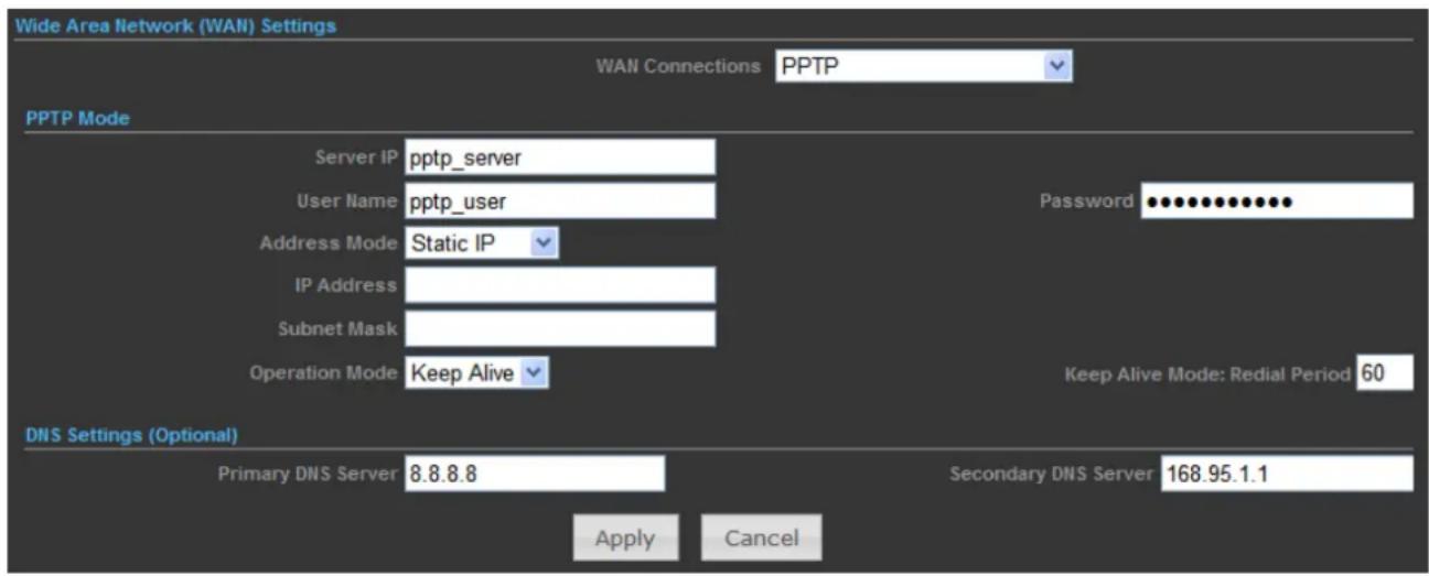
Figure 5-5-6
The page includes the following fields:
| Object Description | |
| • WAN Connections | Select PPTP from the list. |
| • Server IP | Enter the IP address of the PPTP server. |
| • User Name / Password | Enter the User Name and Password provided by your ISP. These fields are case-sensitive. |
| • Address Mode | Static IP/ Dynamic IP: Choose either as you are given by your ISP and If you choose static IP and enter the domain name, you should also enter the DNS assigned by your ISP. And click the Save button. |
| • IP Address | Enter the User Name and Password provided by your ISP. These fields are case-sensitive. |
| • Subnet Mask | Enter the subnet Mask in dotted-decimal notation provided by your ISP, usually is 255.255.255.0 |
| • Operation Mode | Keep Alive: Being constantly connected. |
| • Keep Alive Mode | Set up the redial period after the disconnection. The default setting is "60 seconds". |
| • Primary DNS Server | (Optional) Enter the DNS IP address in dotted-decimal notation provided by your ISP. |
| • Secondary DNS Server | (Optional) Enter another DNS IP address in dotted-decimal notation provided by your ISP. |
5.5.1.6. L2TP
If your ISP provides L2TP connection, please select L2TP. And enter the following parameters.
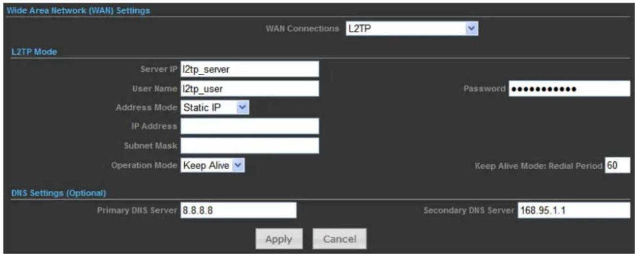
Figure 5-5-7
The page includes the following fields:
| Object Description | |
| • WAN Connections | Select L2TP from the list. |
| • Server IP | Enter the IP address of the L2TP server. |
| User Name / Password | Enter the User Name and Password provided by your ISP. These fields are case-sensitive. |
| Address Mode | Static IP/ Dynamic IP: Choose either as you are given by your ISP and If you choose static IP and enter the domain name, you should also enter the DNS assigned by your ISP. And click the Save button. |
| IP Address | Enter the User Name and Password provided by your ISP. These fields are case-sensitive. |
| Subnet Mask | Enter the subnet Mask in dotted-decimal notation provided by your ISP, usually is 255.255.255.0 |
| Operation Mode | Keep Alive: Being constantly connected. |
| Keep Alive Mode | Set up the redial period after the disconnection. The default setting is "60 seconds". |
| Primary DNS Server | (Optional) Enter the DNS IP address in dotted-decimal notation provided by your ISP. |
| Secondary DNS Server | (Optional) Enter another DNS IP address in dotted-decimal notation provided by your ISP. |
5.5.2 LAN
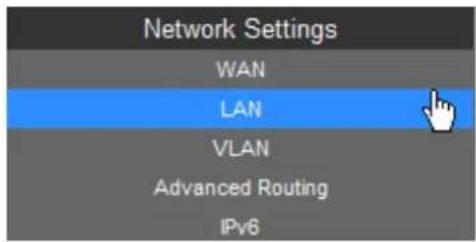

Figure 5-5-8
The page includes the following fields:
| Object Description | |
| • MAC Address | Display the LAN port MAC address of the Wireless AP. |
| • IP Address | The Wireless AP's LAN IP.The default is 192.168.1.1. You can change it according to your need. |
| • Subnet Mask | Enter the subnet mask of the LAN IP. |
5.5.2.1. DHCP Server
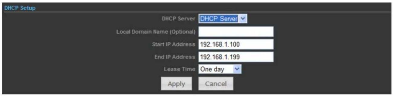
Figure 5-5-9
The page includes the following fields:
| Object Description | |
| DHCP Server | Select DHCP Server to enable DHCP server feature. |
| Local Domain Name (Optional) | (Optional) Input the domain name of your network. |
| Start IP Address | Enter the starting IP address for the DHCP server's IP assignment. |
| End IP Address | Enter the ending IP address for the DHCP server's IP assignment. |
| Lease Time | The length of time for the IP address lease. Configuring a proper lease time improves the efficiency for the DHCP server to reclaim disused IP addresses. |
To benefit from the DHCP server feature, you must set all LAN PCs to DHCP clients by selecting the "Obtain an IP Address Automatically" radio buttons thereon.
5.5.2.2. DHCP Relay

Figure 5-5-10
The page includes the following fields:
| Object Description | |
| DHCP Server | Select DHCP Relay to enable DHCP relay feature. |
| DHCP Relay | A DHCP relay agent is any host that forwards DHCP packets between clients and servers.Configure the IP address of DHCP Relay host. |
5.5.3 VLAN
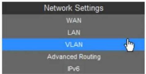
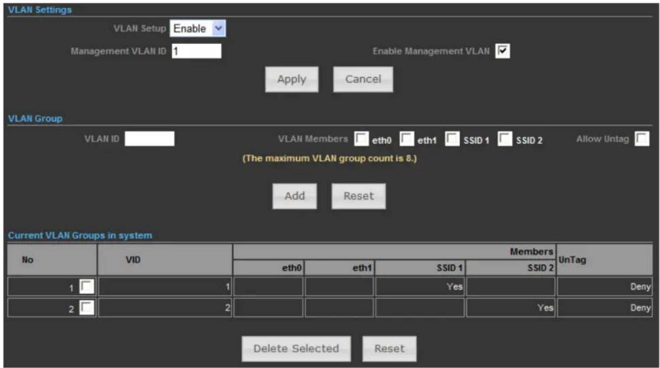
Figure 5-5-11
The page includes the following fields:
| Object Description | |
| • VLAN Setup | Check this box to enable the VLAN function. |
| • Management VLAN ID | Configure a specified VLAN to be the management VLAN. |
| • Enable Management VLAN ID | Check this box to enable the Management VLAN function. |
| • VLAN ID | The ID of a VLAN. Only in the same VLAN can a wireless PC and a wired PC communicate with each other. The value can be between 1 and 4095. If the VLAN function is enabled, when AP forwards packets, the packets out from the LAN port will be added with an IEEE 802.1Q VLAN Tag, whose VLAN ID is just the ID of the VLAN where the sender belongs. |
5.5.4 Advanced Routing
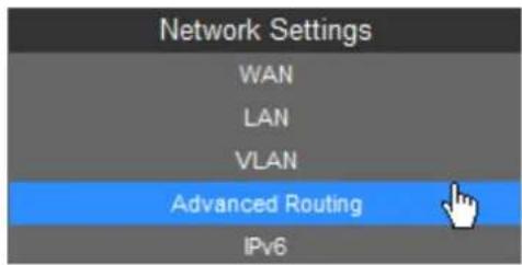
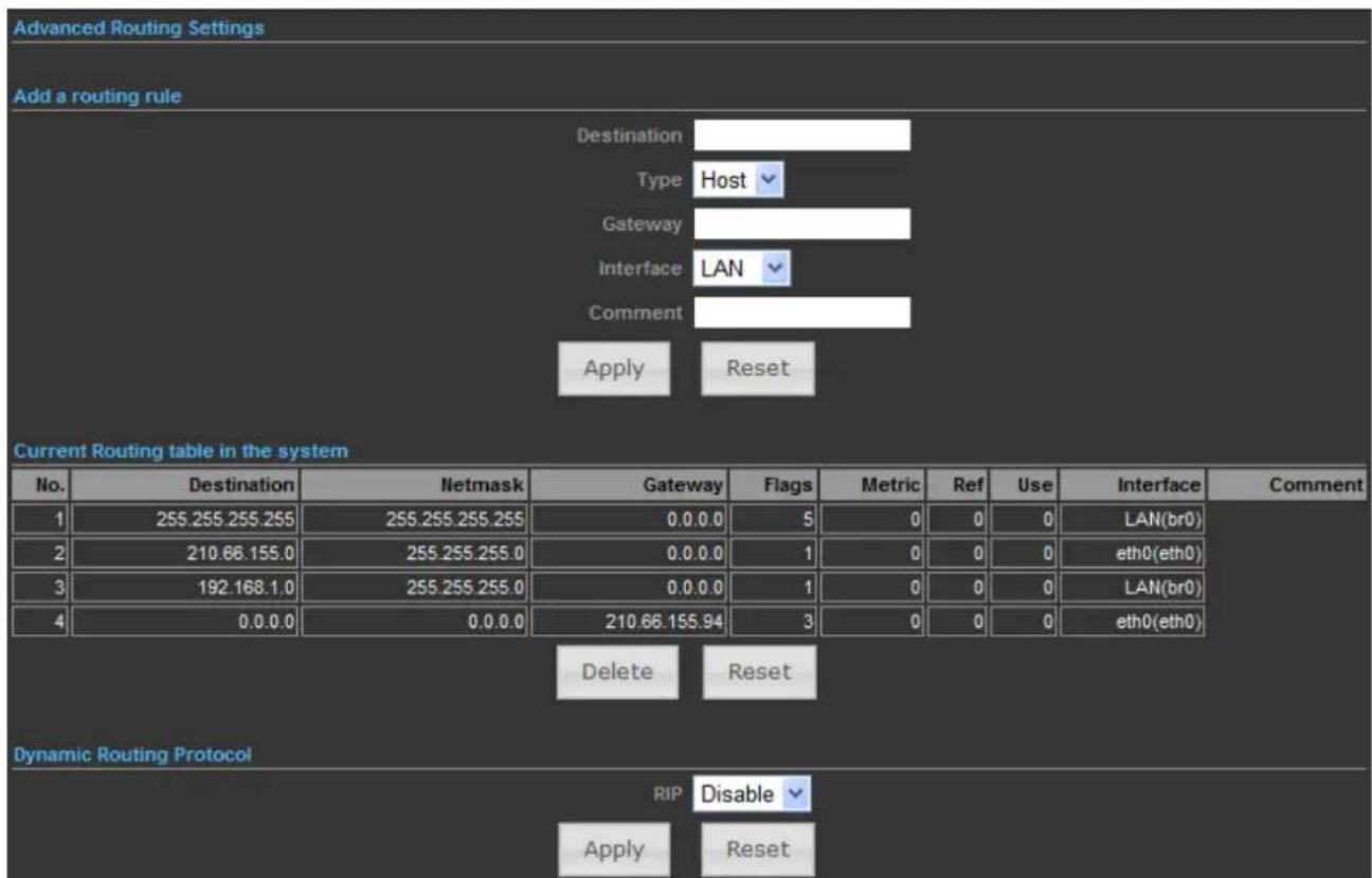
Figure 5-5-12
The page includes the following fields:
| Object Description | |
| • Destination | The IP address of packets that can be routed. |
| • Type | Defines the type of destination. ( Host: Signal IP address / Net: Portion of Network ) |
| • Gateway | Defines the packets destination next hop |
| • Interface | Select interface to which a static routing subnet is to be applied |
| • Comment | Help identify the routing |
| • Dynamic Routing Protocol | Enable or disable the RIP (Routing Information Protocol) for the WAN or LAN interface.It supports RIP v1 and v2. |
5.5.5 IPv6
Use this section to configure your IPv6 Connection type. If you are unsure of your connection method, please contact your Internet Service Provider.
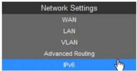
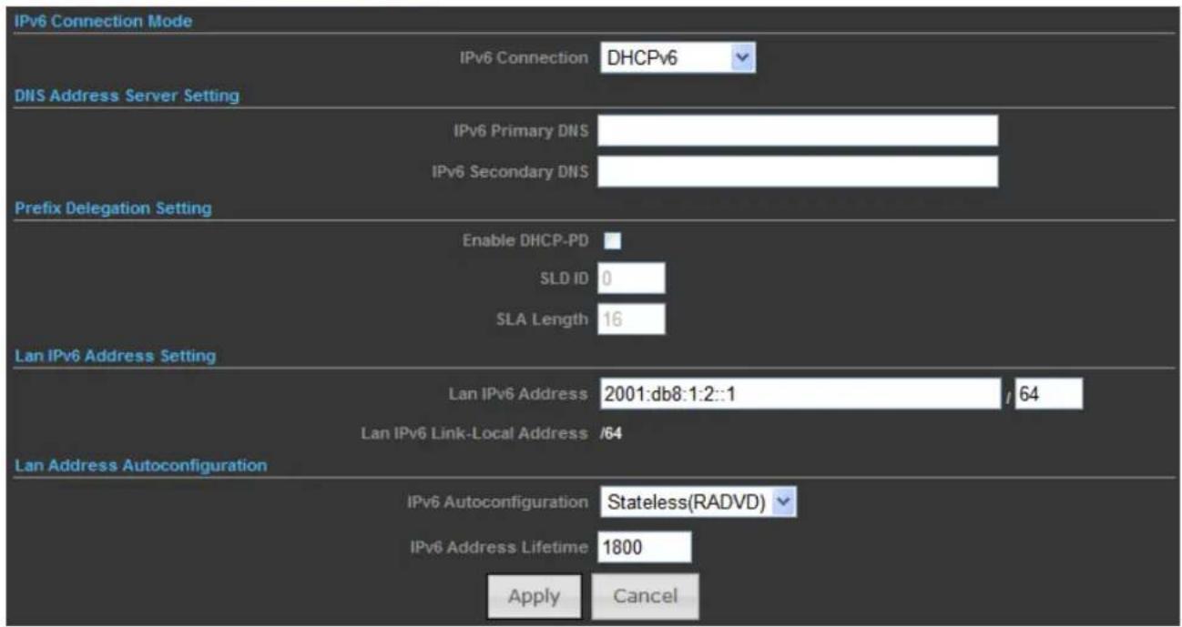
Figure 5-5-13
The page includes the following fields:
| Object Description | |
| IPv6 Connection Mode | Choose the mode to be used by the AP/Router to the IPv6 Internet.There are 7 connection modes available:Static, SLAAC, DHCPv6, 6to4 Tunnel, 6in4 Tunnel, PPPoE, and Pass Through. |
| DNS Address Server Setting | Enter the IPv6 Primary DNS & IPv6 Secondary DNS to this section. |
| Prefix Delegation Setting | Enter the IPv6 Prefix Delegation information provided by your Internet Service Provider (ISP). |
| LAN IPv6 Address Setting | Use this section to configure the internal network settings of your AP/Router. If you change the LAN IPv6 Address here, you may need to adjust your PC network settings to access the network again. |
| LAN Address Auto | IPv6 offers two types of autoconfiguration: Stateful (DHCPv6) & |
| configuration | Stateless (RADVD). |
| Stateful (DHCPv6):This type of configuration is suitable for small organizations and individuals. It allows each host to determine its address from the contents of received user advertisements. It makes use of the IEEE EUI-64 standard to define the network ID portion of the address. | |
| Stateless(RADVD):With Stateless Autoconfiguration, a host gains an address via an interface automatically "leasing" an address and does not require the establishment of an server to delve out address space. |
5.6 Wireless Settings
You could configure the minimum number of Wireless settings for communication, such as Network Name (SSID) and Channel. The Access Point can be set simply with only the minimum setting items.
5.6.1 Basic
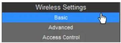
5.6.1.1. Wireless Mode – Access Point
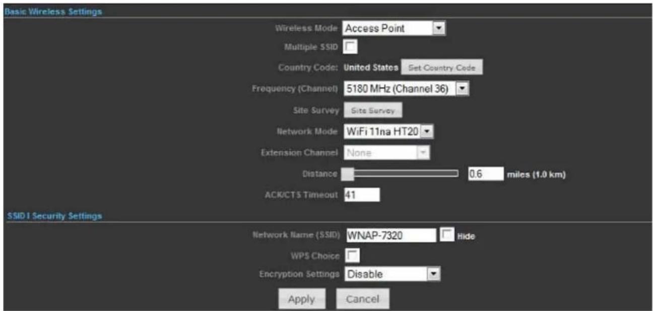
Figure 5-6-1
The page includes the following fields:
| Object Description | |
| • Wireless Mode | Click to select Wireless Mode from pull down menu.There are 4 options available:■ Access Point:This mode allows wireless clients or Stations(STA) to access■ WDS Access Point:This mode enables the wireless interconnection of Access Point in an IEEE802.11 network .and accept wireless clients at the same time.■ WDS Repeater:Set to this mode to enable the wireless access point repeat the signal of root access point using WDS.■ WDS Client:Set to this mode to enable wireless client using WDS to connect to the WDS Access Point. |
| • Multiple SSID | There is one more SSID available. Select the checkbox to enable it, enter the descriptive names that you want to use. |
| • Country Code | Set your country code by clicking the “Set Country Code”. |
| • Frequency (Channel) | Set the channel you would like to use. The channel range will be changed by selecting different domain. |
| • Site Survey | Click “Site Survey” button to observe the signal of remote sites. |
| • Network Mode | Select the operating channel width to WiFi 11na (mixed), HT20 or HT40MHz. |
| • Extension Channel | An extension channel is a secondary channel used to bond with the primary channel to increase this range to 40MHz. Bonded channels allow for greater bandwidth on the local network. |
| • Distance | To decrease the chances of data retransmission at long distance, the IEEE 802.11a/n Wireless Outdoor CPE can automatically adjust proper ACK timeout value by specifying distance of the two nodes. |
| • ACK/CTS Timeout | ACK/CTS Timeout settings are for long distance links. It is important to tweak settings to achieve the optimal result based on requirement.The device’s default settings should be sufficient for most applications.The value is auto determined by distance between the radios, data rate of average environment. |
| • Network Name (SSID) | It is the wireless network name. The SSID can be 32 bytes long.User can use the default SSID or change it.The default SSID is WNAP-7320. |
| • WPS Choice | Enable it to use WPS associating with AP or Client device. |
| • Encryption Settings | Select the encryption type that you would like to use. |
| • WPA Algorithms | Select the WPA Algorithms that you would like to use. |
| • Key Renewal Interval (Seconds) | The key renewal time is the period of time that the AP uses the same key before a new one is generated. |
| • Pre-Shared Key | Data encryption and key are required for wireless authentication. |
5.6.1.2. Wireless Mode – WDS Access Point
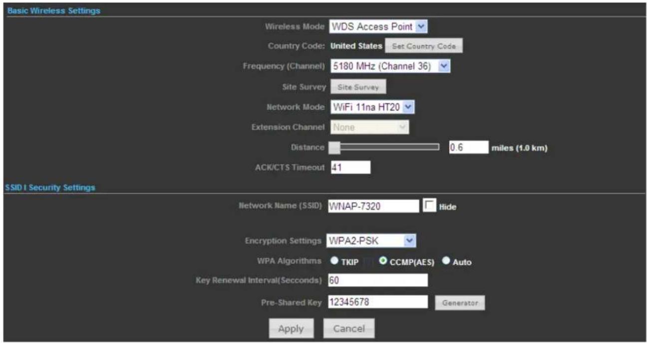
Figure 5-6-2
The page includes the following fields:
| Object Description | |
| • Wireless Mode | Click to select Wireless Mode from pull down menu.There are 4 options available:Access Point:This mode allows wireless clients or Stations(STA) to accessWDS Access Point:This mode enables the wireless interconnection of Access Point in an IEEE802.11 network .and accept wireless clients at the same time.WDS Repeater:Set to this mode to enable the wireless access point repeat the signal of root access point using WDS.WDS Client:Set to this mode to enable wireless client using WDS to connect to the WDS Access Point. |
| Country Code | Set your country code by clicking the “Set Country Code”. |
| Frequency (Channel) | Set the channel you would like to use. The channel range will be changed by selecting different domain. |
| Site Survey | Click “Site Survey” button to observe the signal of remote sites. |
| Network Mode | Select the operating channel width to WiFi 11na (mixed), HT20 or HT40MHz. |
| Extension Channel | An extension channel is a secondary channel used to bond with the primary channel to increase this range to 40MHz. Bonded channels allow for greater bandwidth on the local network. |
| Distance | To decrease the chances of data retransmission at long distance, the IEEE 802.11a/n Wireless Outdoor CPE can automatically adjust proper ACK timeout value by specifying distance of the two nodes. |
| ACK/CTS Timeout | ACK/CTS Timeout settings are for long distance links. It is important to tweak settings to achieve the optimal result based on requirement.The device's default settings should be sufficient for most applications.The value is auto determined by distance between the radios, data rate of average environment. |
| Network Name (SSID) | It is the wireless network name. The SSID can be 32 bytes long.User can use the default SSID or change it.The default SSID is WNAP-7320. |
| Encryption Settings | Select the encryption type that you would like to use. |
| WPA Algorithms | Select the WPA Algorithms that you would like to use. |
| Key Renewal Interval (Seconds) | The key renewal time is the period of time that the AP uses the same key before a new one is generated. |
| Pre-Shared Key | Data encryption and key are required for wireless authentication. |
5.6.1.3. Wireless Mode – WDS Repeater
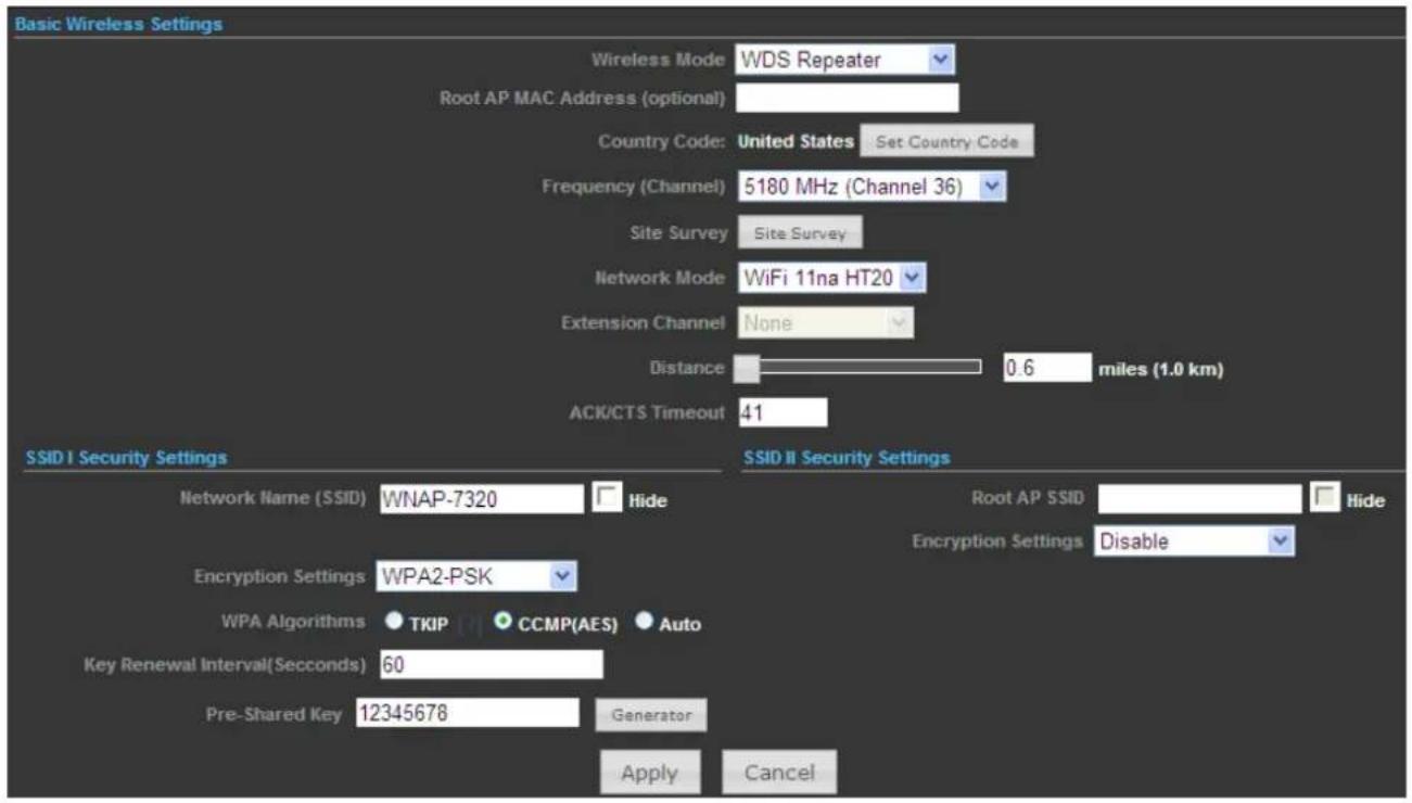
Figure 5-6-3
The page includes the following fields:
| Object Description | |
| • Wireless Mode | Click to select Wireless Mode from pull down menu.There are 4 options available:■ Access Point:This mode allows wireless clients or Stations(STA) to access■ WDS Access Point:This mode enables the wireless interconnection of Access Point in an IEEE802.11 network .and accept wireless clients at the same time.■ WDS Repeater:Set to this mode to enable the wireless access point repeat the signal of root access point using WDS.■ WDS Client:Set to this mode to enable wireless client using WDS to connect to the WDS Access Point. |
| • Root AP MAC Address (optional) | Fill out the Root AP's MAC Address enable it to connect to the Root AP using WDS. |
| • Country Code | Set your country code by clicking the “Set Country Code”. |
| Frequency (Channel) | Set the channel you would like to use. The channel range will be changed by selecting different domain. |
| Site Survey | Click "Site Survey" button to observe the signal of remote sites. |
| Network Mode | Select the operating channel width to WiFi 11na (mixed), HT20 or HT40MHz. |
| Extension Channel | An extension channel is a secondary channel used to bond with the primary channel to increase this range to 40MHz. Bonded channels allow for greater bandwidth on the local network. |
| Distance | To decrease the chances of data retransmission at long distance, the IEEE 802.11a/n Wireless Outdoor CPE can automatically adjust proper ACK timeout value by specifying distance of the two nodes. |
| ACK/CTS Timeout | ACK/CTS Timeout settings are for long distance links. It is important to tweak settings to achieve the optimal result based on requirement. The device's default settings should be sufficient for most applications.The value is auto determined by distance between the radios, data rate of average environment. |
| Network Name (SSID) | It is the wireless network name of itself. The SSID can be 32 bytes long.User can use the default SSID or change it.The default SSID is WNAP-7320. |
| Root AP SSID | It is the wireless network name of Root AP.The SSID must be the same with Root AP so that the connection can be established successfully. |
| Encryption Settings | Select the encryption type that you would like to use. |
| WPA Algorithms | Select the WPA Algorithms that you would like to use. |
| Key Renewal Interval (Seconds) | The key renewal time is the period of time that the AP uses the same key before a new one is generated. |
| Pre-Shared Key | Data encryption and key are required for wireless authentication. |
5.6.1.4. Wireless Mode – WDS Client
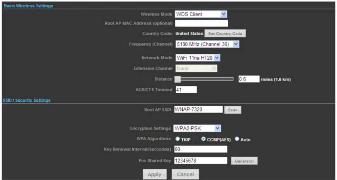
Figure 5-6-4
The page includes the following fields:
| Object Description | |
| • Wireless Mode | Click to select Wireless Mode from pull down menu.There are 4 options available:■ Access Point:This mode allows wireless clients or Stations(STA) to access■ WDS Access Point:This mode enables the wireless interconnection of Access Point in an IEEE802.11 network .and accept wireless clients at the same time.■ WDS Repeater:Set to this mode to enable the wireless access point repeat the signal of root access point using WDS.■ WDS Client:Set to this mode to enable wireless client using WDS to connect to the WDS Access Point. |
| • Root AP MAC Address (optional) | Fill out the Root AP's MAC Address enable it to connect to the Root AP using WDS. |
| • Country Code | Set your country code by clicking the “Set Country Code”. |
| Frequency (Channel) | Set the channel you would like to use. The channel range will be changed by selecting different domain. |
| Network Mode | Select the operating channel width to WiFi 11na (mixed), HT20 or HT40MHz. |
| Extension Channel | An extension channel is a secondary channel used to bond with the primary channel to increase this range to 40MHz. Bonded channels allow for greater bandwidth on the local network. |
| Distance | To decrease the chances of data retransmission at long distance, the IEEE 802.11a/n Wireless Outdoor CPE can automatically adjust proper ACK timeout value by specifying distance of the two nodes. |
| ACK/CTS Timeout | ACK/CTS Timeout settings are for long distance links. It is important to tweak settings to achieve the optimal result based on requirement.The device's default settings should be sufficient for most applications.The value is auto determined by distance between the radios, data rate of average environment. |
| Root AP SSID | It is the wireless network name of Root AP.The SSID must be the same with Root AP so that the connection can be established successfully.Click "Scan" to site survey the Root AP. |
| Encryption Settings | Select the encryption type that you would like to use. |
| WPA Algorithms | Select the WPA Algorithms that you would like to use. |
| Key Renewal Interval (Seconds) | The key renewal time is the period of time that the AP uses the same key before a new one is generated. |
| Pre-Shared Key | Data encryption and key are required for wireless authentication. |
5.6.2 Profile Settings
In Client Bridge and Client Router operation modes, please go to "Advanced-> Wireless Settings-> Profile Settings" to configure the wireless client function to connect with the wireless AP.

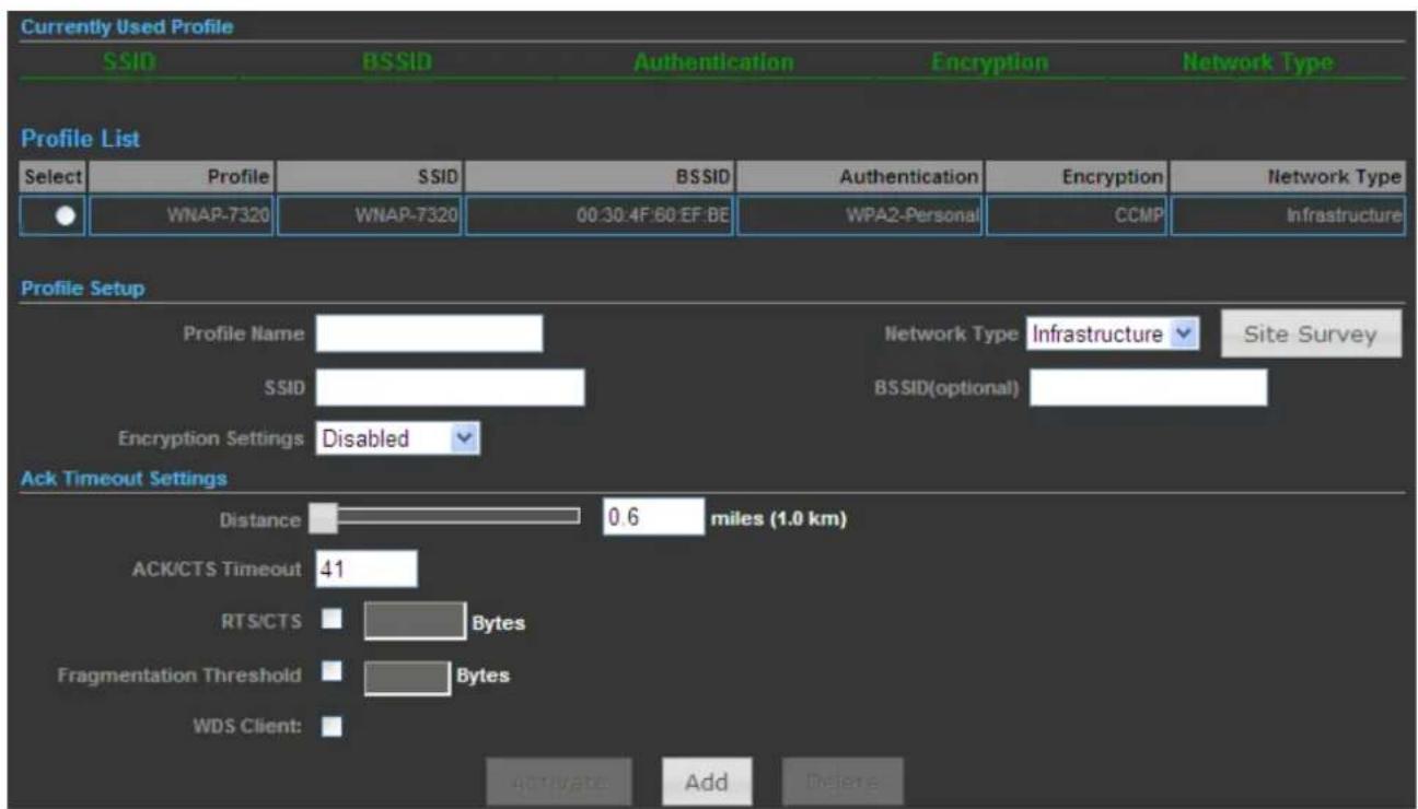
Figure 5-6-5
The page includes the following fields:
| Object Description | |
| • Profile Name | Fill out the Root AP's MAC Address enable it to connect to the Root AP using WDS. |
| • Network Type | Set the Network Type that you would like to use.■ Infrastructure:Infrastructure networks consist of the networked devices and the wireless access point or wireless router. Each device must connect to the access point before having access to other computers on the network.■ Ad-hoc:In an ad hoc network, each device's network adapter directly communicates with other devices. |
| • SSID | It is the wireless network name of Root AP. |
| • BSSID (optional) | Indicate the Basic Service Set ID of the associated AP |
| • Encryption Settings | Select the encryption type that you would like to use. |
| • Distance | To decrease the chances of data retransmission at long distance, the IEEE 802.11a/n Wireless Outdoor CPE can automatically adjust proper ACK timeout value by specifying distance of the two nodes. |
| • ACK/CTS Timeout | ACK/CTS Timeout settings are for long distance links. It is important to tweak settings to achieve the optimal result based on requirement. The device's default settings should be sufficient for most applications.The value is auto determined by distance between the radios, data rate of average environment. |
| • RTS/CTS | RTS/CTS (Request to Send / Clear to Send) is the optional mechanism used by the 802.11 wireless networking protocol to reduce frame collisions introduced by the hidden node problem.You can enter a setting ranging from 0 to 2347 bytes. |
| • Fragmentation Threshold | The fragmentation threshold determines the size at which packets are fragmented (sent as several pieces instead of as one block). Use a low setting in areas where communication is poor or where there is a great deal of radio interference. This function will help you to improve the network performance. |
| • WDS Client | Check it to enable WDS Client function. |
5.6.3 Advanced
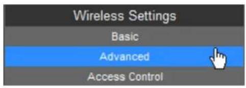
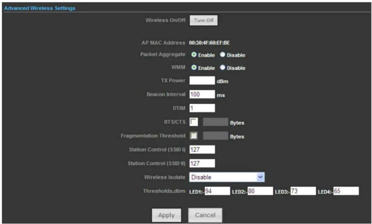
Figure 5-6-6
The page includes the following fields:
| Object Description | |
| • Wireless On/Off | Click this button to switch the Wireless Radio On or Off. |
| • AP MAC Address | Display the AP MAC Address of wireless interface. |
| • Packet Aggregate | In a packet-based communications network, packet aggregation is the process of joining multiple packets together into a single transmission unit, in order to reduce the overhead associated with each transmission. |
| • WMM | WMM function can guarantee the packets with high-priority messages being transmitted preferentially. It is strongly recommended enabled. |
| • TX Power | The range of TX power is “3~27dBm”. In case of shortening the distance and the coverage of the wireless network, input a smaller value to reduce the radio transmission power. For example, input9 to apply 33% Tx power. |
| • Beacon Interval | The beacons are the packets sent by the Device to synchronize a wireless network. Beacon Interval value determines the time interval of the beacons. You can specify a value between 20-1000 milliseconds. The default value is 100. |
| • DTIM | This value determines the interval of the Delivery Traffic Indication Message (DTIM). You can specify the value between 1-255 Beacon Intervals. The default value is 1, which indicates the DTIM Interval is the same as Beacon Interval. |
| • RTS/CTS | The RTS/CTS mechanism is widely used in wireless networks in order to avoid packet collisions and, thus, achieve high throughput. |
| • Fragmentation Threshold | This value is the maximum size determining whether packets will be fragmented. Setting the Fragmentation Threshold too low may result in poor network performance since excessive packets. 2346 is the default setting and is recommended. |
| • Station Control (SSID I) | Fill out the Station Control value of SSID I. |
| • Station Control (SSID II) | Fill out the Station Control value of SSID II. |
| • Wireless Isolate | Isolate all connected wireless stations so that wireless stations cannot access each other through WLAN. This function will be disabled if WDS/Bridge is enabled. |
| • Thresholds, dbm | Set the AP to the external LED lights and wireless signal strength received correspondence, when the AP receives the wireless signal, according to the wireless signal strength, the corresponding LED will be lit. |
5.6.4 Access Control
Choose menu "Advanced-> Wireless Settings-> Access Control" to configure the filtering rules for the clients would like to associate with Wireless AP.
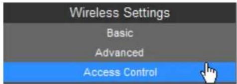
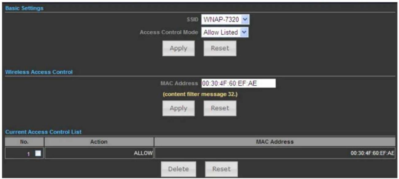
Figure 5-6-7
The page includes the following fields:
| Object Description | |
| • SSID | Select the SSID which you would like to configure access control. |
| • Access Control Mode | Allow Listed: allow the packets not specified by any access control policy to pass through the AP Router.Deny Listed: deny the packets not specified by any access control policy to pass through the AP Router. |
| • MAC Address | Configure the MAC Address to apply the access control. |
| • Current Access Control List | Display the current Access Control List. |
5.7 Logout
Select "Logout", and then click "Yes" to logout the system.

Figure 5-7-1

Figure 5-7-2
Appendix A: FAQ
A.1 What and how to find my PC's IP and MAC address?
IP address is the identifier for a computer or device on a TCP/IP network. Networks using the TCP/IP protocol route messages based on the IP address of the destination. The format of an IP address is a 32-bit numeric address written as four numbers separated by periods. Each number can be zero to 255. For example, 191.168.1.254 could be an IP address
The MAC (Media Access Control) address is your computer's unique hardware number. (On an Ethernet LAN, it's the same as your Ethernet address.) When you're connected to the Internet from your computer (or host as the Internet protocol thinks of it), a correspondence table relates your IP address to your computer's physical (MAC) address on the LAN.
To find your PC's IP and MAC address,
(1) Open the Command program in the Microsoft Windows.
(2) Type in "ipconfig /all", then press the Enter button.
(3) Your PC's IP address is the one entitled IP Address and your PC's MAC address is the one entitled Physical Address.
A.2 What is Wireless LAN?
A wireless LAN (WLAN) is a network that allows access to Internet without the need for any wired connections to the user's machine.
A.3 What are ISM bands?
ISM stands for Industrial, Scientific and Medical; radio frequency bands that the Federal Communications Commission (FCC) authorized for wireless LANs. The ISM bands are located at 915 +/-13 MHz, 2450 +/-50 MHz and 5800 +/-75 MHz.
A.4 How does wireless networking work?
The 802.11 standard define two modes: infrastructure mode and ad hoc mode. In infrastructure mode, the wireless network consists of at least one access point connected to the wired network infrastructure and a set of wireless end stations. This configuration is called a Basic Service Set (BSS). An Extended Service Set (ESS) is a set of two or more BSSs forming a single sub-network. Since most corporate WLANs require access to the wired LAN for services (file servers, printers, Internet links) they will operate in infrastructure mode.
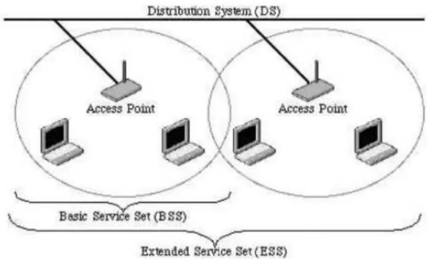
flowchart
graph TD
    A["Access Point"] -->|Basic Service Set (BSS)| B["Distribution System (DS)"]
    C["Access Point"] -->|Extended Service Set (ESS)| D["Distribution System (DS)"]
    style A fill:#f9f,stroke:#333
    style C fill:#ccf,stroke:#333
    style B fill:#cfc,stroke:#333
    style D fill:#fcc,stroke:#333
Example 1: wireless Infrastructure Mode
Ad hoc mode (also called peer-to-peer mode or an Independent Basic Service Set, or IBSS) is simply a set of 802.11 wireless stations that communicate directly with one another without using an access point or any connection to a wired network. This mode is useful for quickly and easily setting up a wireless network anywhere that a wireless infrastructure does not exist or is not required for services, such as a hotel room, convention center, or airport, or where access to the wired network is barred (such as for consultants at a client site).
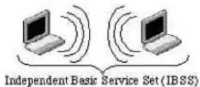
Example 2: wireless Ad Hoc Mode
A.5 What is BSSID?
A six-byte address is that distinguish a particular a particular access point from others. Also know as just SSID. Serve as a network ID or name.
A.6 What is ESSID?
The Extended Service Set ID (ESSID) is the name of the network you want to access. It is used to identify different wireless networks.
A.7 What are potential factors that may causes interference?
Factors of interference:
■ Obstacles: walls, ceilings, furniture... etc.
■ Building Materials: metal door, aluminum studs.
■ Electrical devices: microwaves, monitors and electrical motors.
Solutions to overcome the interferences:
■ Minimizing the number of walls and ceilings.
■ Position the WLAN antenna for best reception.
- Keep WLAN devices away from other electrical devices, eg: microwaves, monitors, electric motors...etc.
■ Add additional WLAN Access Points if necessary.
A.8 What are the Open System and Shared Key authentications?
IEEE 802.11 supports two subtypes of network authentication services: open system and shared key. Under open system authentication, any wireless station can request authentication. The station that needs to authenticate with another wireless station sends an authentication management frame that contains the identity of the sending station. The receiving station then returns a frame that indicates whether it recognizes the sending station. Under shared key authentication, each wireless station is assumed to have received a secret shared key over a secure channel that is independent from the 802.11 wireless network communications channel.
A.9 What is WEP?
An option of IEEE 802.11 function is that offers frame transmission privacy similar to a wired network. The Wired Equivalent Privacy generates secret shared encryption keys that both source and destination stations can use to alert frame bits to avoid disclosure to eavesdroppers.
WEP relies on a secret key that is shared between a mobile station (e.g. a laptop with a wireless Ethernet card) and an access point (i.e. a base station). The secret key is used to encrypt packets before they are transmitted, and an integrity check is used to ensure that packets are not modified in transit.
A.10 What is Fragment Threshold?
The proposed protocol uses the frame fragmentation mechanism defined in IEEE 802.11 to achieve parallel transmissions. A large data frame is fragmented into several fragments each of size equal to fragment threshold. By tuning the fragment threshold value, we can get varying fragment sizes. The determination of an efficient fragment threshold is an important issue in this scheme. If the fragment threshold is small, the overlap part of the master and parallel transmissions is large. This means the spatial reuse ratio of parallel transmissions is high. In contrast, with a large fragment threshold, the overlap is small and the spatial reuse ratio is low. However high fragment threshold leads to low fragment overhead. Hence there is a trade-off between spatial re-use and fragment overhead.
Fragment threshold is the maximum packet size used for fragmentation. Packets larger than the size programmed in this field will be fragmented.
If you find that your corrupted packets or asymmetric packet reception (all send packets, for example). You may want to try lowering your fragmentation threshold. This will cause packets to be broken into smaller fragments.
These small fragments, if corrupted, can be resent faster than a larger fragment. Fragmentation increases overhead, so you'll want to keep this value as close to the maximum value as possible.
A.11 What is RTS (Request to Send) Threshold?
The RTS threshold is the packet size at which packet transmission is governed by the RTS/CTS transaction. The IEEE 802.11-1997 standard allows for short packets to be transmitted without RTS/CTS transactions. Each station can have a different RTS threshold. RTS/CTS is used when the data packet size exceeds the defined RTS threshold. With the CSMA/CA transmission mechanism, the transmitting station sends out an RTS packet to the receiving station, and waits for the receiving station to send back a CTS (Clear to Send) packet before sending the actual packet data.
This setting is useful for networks with many clients. With many clients, and a high network load, there will be many more collisions. By lowering the RTS threshold, there may be fewer collisions, and performance should improve. Basically, with a faster RTS threshold, the system can recover from problems faster. RTS packets consume valuable bandwidth, however, so setting this value too low will limit performance.
A.12 What is Beacon Interval?
In addition to data frames that carry information from higher layers, 802.11 include management and control frames that support data transfer. The beacon frame, which is a type of management frame, provides the "heartbeat" of a wireless LAN, enabling stations to establish and maintain communications in an orderly fashion.
Beacon Interval represents the amount of time between beacon transmissions. Before a station enters power save mode, the station needs the beacon interval to know when to wake up to receive the beacon (and learn whether there are buffered frames at the access point).
A.13 What is Preamble Type?
There are two preamble types defined in IEEE 802.11 specification. A long preamble basically gives the decoder more time to process the preamble. All 802.11 devices support a long preamble. The short preamble is designed to improve efficiency (for example, for VoIP systems). The difference between the two is in the Synchronization field. The long preamble is 128 bits, and the short is 56 bits.
A.14 What is SSID Broadcast?
Broadcast of SSID is done in access points by the beacon. This announces your access point (including various bits of information about it) to the wireless world around it. By disabling that feature, the SSID configured in the client must match the SSID of the access point.
Some wireless devices don't work properly if SSID isn't broadcast (for example the D-link DWL-120 USB 802.11b adapter). Generally if your client hardware supports operation with SSID disabled, it's not a bad idea to run that way to enhance network security. However it's no replacement for WEP, MAC filtering or other protections.
A.15 What is Wi-Fi Protected Access (WPA)?
Wi-Fi's original security mechanism, Wired Equivalent Privacy (WEP), has been viewed as insufficient for securing confidential business communications. A longer-term solution, the IEEE 802.11i standard, is under development. However, since the IEEE 802.11i standard is not expected to be published until the end of 2003, several members of the WI-Fi Alliance teamed up with members of the IEEE 802.11i task group to develop a significant near-term enhancement to Wi-Fi security. Together, this team developed Wi-Fi Protected Access.
To upgrade a WLAN network to support WPA, Access Points will require a WPA software upgrade. Clients will require a software upgrade for the network interface card, and possibly a software update for the operating system. For enterprise networks, an authentication server, typically one that supports RADIUS and the selected EAP authentication protocol, will be added to the network.
A.16 What is WPA2?
It is the second generation of WPA. WPA2 is based on the final IEEE 802.11i amendment to the 802.11 standard.
A.17 What is 802.1x Authentication?
802.1x is a framework for authenticated MAC-level access control, defines Extensible Authentication Protocol (EAP) over LANs (WAPOL). The standard encapsulates and leverages much of EAP, which was defined for dial-up authentication with Point-to-Point Protocol in RFC 2284.
Beyond encapsulating EAP packets, the 802.1x standard also defines EAPOL messages that convey the shared key information critical for wireless security.
A.18 What is Temporal Key Integrity Protocol (TKIP)?
The Temporal Key Integrity Protocol, pronounced tee-kip, is part of the IEEE 802.11i encryption standard for wireless LANs. TKIP is the next generation of WEP, the Wired Equivalency Protocol, which is used to secure 802.11 wireless LANs. TKIP provides per-packet key mixing, a message integrity check and a re-keying mechanism, thus fixing the flaws of WEP.
A.19 What is Advanced Encryption Standard (AES)?
Security issues are a major concern for wireless LANs, AES is the U.S. government's next-generation cryptography algorithm, which will replace DES and 3DES.
A.20 What is Inter-Access Point Protocol (IAPP)?
The IEEE 802.11f Inter-Access Point Protocol (IAPP) supports Access Point Vendor interoperability, enabling roaming of 802.11 Stations within IP subnet.
IAPP defines messages and data to be exchanged between Access Points and between the IAPP and high layer management entities to support roaming. The IAPP protocol uses TCP for inter-Access Point communication and UDP for RADIUS request/response exchanges. It also uses Layer 2 frames to update the forwarding tables of Layer 2 devices.
A.21 What is Wireless Distribution System (WDS)?
The Wireless Distribution System feature allows WLAN AP to talk directly to other APs via wireless channel, like the wireless WDS or repeater service.
A.22 What is Universal Plug and Play (UPnP)?
UPnP is an open networking architecture that consists of services, devices, and control points. The ultimate goal is to allow data communication among all UPnP devices regardless of media, operating system, programming language, and wired/wireless connection.
A.23 What is Maximum Transmission Unit (MTU) Size?
Maximum Transmission Unit (MTU) indicates the network stack of any packet is larger than this value will be fragmented before the transmission. During the PPP negotiation, the peer of the PPP connection will indicate its MRU and will be accepted. The actual MTU of the PPP connection will be set to the smaller one of MTU and the peer's MRU.
A.24 What is Clone MAC Address?
Clone MAC address is designed for your special application that request the clients to register to a server machine with one identified MAC address. Since that all the clients will communicate outside world through the WLAN Broadband Router, so have the cloned MAC address set on the WLAN Broadband Router will solve the issue.
A.25 What is DDNS?
DDNS is the abbreviation of Dynamic Domain Name Server. It is designed for user owned the DNS server with dynamic WAN IP address.
A.26 What is NTP Client?
NTP client is designed for fetching the current timestamp from internet via Network Time protocol. User can specify time zone, NTP server IP address.
A.27 What is VPN?
VPN is the abbreviation of Virtual Private Network. It is designed for creating point-to point private link via shared or public network.
A.28 What is IPSEC?
IPSEC is the abbreviation of IP Security. It is used to transferring data securely under VPN.
A.29 What is WLAN Block Relay between Clients?
An Infrastructure Basic Service Set is a BSS with a component called an Access Point (AP). The access point provides a local relay function for the BSS. All stations in the BSS communicate with the access point and no longer communicate directly. All frames are relayed between stations by the access point. This local relay function effectively doubles the range of the IBSS.
A.30 What is WMM?
WMM is based on a subset of the IEEE 802.11e WLAN QoS draft standard. WMM adds prioritized capabilities to Wi-Fi networks and optimizes their performance when multiple concurring applications, each with different latency and throughput requirements, compete for network resources. By using WMM, end-user satisfaction is maintained in a wider variety of environments and traffic conditions. WMM makes it possible for home network users and enterprise network managers to decide which data streams are most important and assign them a higher traffic priority.
A.31 What is WLAN ACK TIMEOUT?
ACK frame has to receive ACK timeout frame. If remote does not receive in specified period, it will be retransmitted.
A.32 What is Modulation Coding Scheme (MCS)?
MCS is Wireless link data rate for 802.11n. The throughput/range performance of an AP will depend on its implementation of coding schemes. MCS includes variables such as the number of spatial streams, modulation, and the data rate on each stream. Radios establishing and maintaining a link must automatically negotiate the optimum MCS based on channel conditions and then continuously adjust the selection of MCS as conditions change due to interference, motion, fading, and other events.
A.33 What is Frame Aggregation?
Every 802.11 packet, no matter how small, has a fixed amount of overhead associated with it. Frame Aggregation combines multiple smaller packets together to form one larger packet. The larger packet can be sent without the overhead of the individual packets. This technique helps improve the efficiency of the 802.11n radio allowing more end user data to be sent in a given time.
A.34 What is Guard Intervals (GI)?
A GI is a period of time between symbol transmission that allows reflections (from multipath) from the previous data transmission to settle before transmitting a new symbol. The 802.11n specifies two guard intervals: 400ns (short) and 800ns (long). Support of the 400ns GI is optional for transmit and receive. The purpose of a guard interval is to introduce immunity to propagation delays, echoes, and reflections to which digital data is normally very sensitive.
Appendix B: Configuring the PC in Windows 7
In this section, we'll introduce how to configure the TCP/IP correctly in Windows 7. First make sure your Network Adapter is working, refer to the adapter's manual if needed.
1) On the Windows taskbar, click the Start button, and then click Control Panel.
2) Click the Network and Sharing Center icon, and then click the Change adapter settings on the left side of the screen.
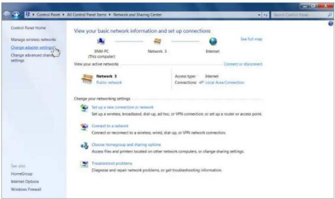
Figure B-1
3) Right click the icon of the network adapter shown in the figure below, and select Properties on the prompt window.
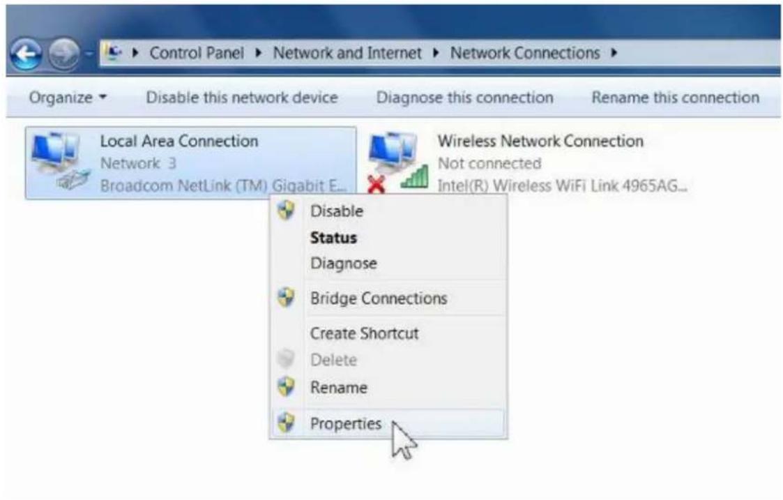
Figure B-2
4) In the prompt page shown below, double click on the Internet Protocol Version 4 (TCP/IPv4).
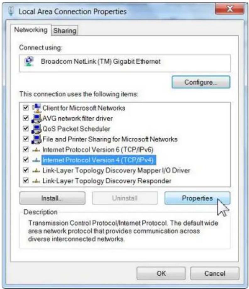
Figure B-3
5) The following TCP/IP Properties window will display and the IP Address tab is open on this window by default.
Now you can configure the TCP/IP protocol below:
Setting IP address manually
1 Select Use the following IP address radio button.
2 If the AP's LAN IP address is 192.168.1.1, type in IP address 192.168.1.x (x is from 2 to 254), and Subnet mask 255.255.255.0.
3 Select Use the following DNS server addresses radio button. In the Preferred DNS Server field you can type the DNS server IP address which has been provided by your ISP
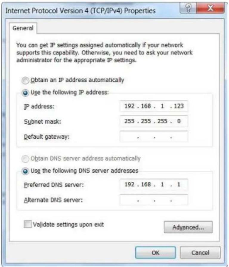
Figure B-4
Now click OK to keep your settings.
Appendix C: Use Planet Smart Discovery to find AP
For easily discover the WNAP-7320 in your Ethernet environment, the Planet Smart Discovery Utility from user's manual CD-ROM is an ideal solution.
The following install instructions guiding you to run the Planet Smart Discovery Utility.
Step 1: Deposit the Planet Smart Discovery Utility in administrator PC.
Step 2: Execute this utility.

Planet_Utility.exe PLANET Corp.
Step 3: Click "Refresh" button to update the current connected devices list, the screen is shown as follow.
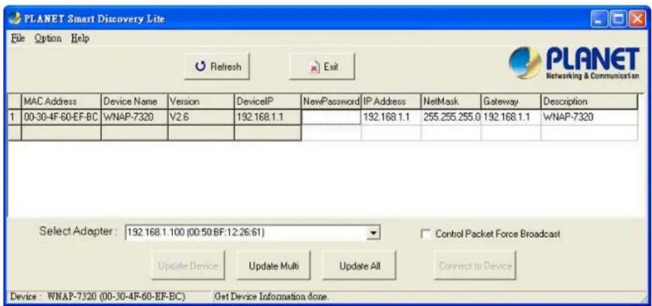
Figure C-1
Step 3: Select the WNAP-7320 from the list, and then click "Connect to Device" button to login the Web Management Configuration Page.

Note
The fields in white background can be modified directly, and then you can apply the new setting by clicking the "Update Device" button.
Appendix D: Specifications
| Product | WNAP-73205GHz 300Mbps 802.11a/n Wireless Outdoor Access Point | |||
| Hardware Specifications | ||||
| Standard support | IEEE 802.11a/n Wireless LANIEEE 802.11i Wireless SecurityIEEE 802.3 10Base-T EthernetIEEE 802.3u 100Base-TX EthernetIEEE 802.3x Flow Control | |||
| Memory | 32 Mbytes DDR SDRAM8 Mbytes Flash | |||
| Interface | Wireless IEEE802.11a/n, 2T2RLAN: 1 x 10/100Base-TX, Auto-MDI/MDIXWAN: 1 x 10/100Base-TX, Auto-MDI/MDIX | |||
| Antenna | Built-in 14dBi Dual-Polarization Antenna- Horizontal: 45 degree- Vertical: 60 degree | |||
| Wireless RF Specifications | ||||
| Wireless Technology | IEEE 802.11aIEEE 802.11n | |||
| Data Rate | IEEE 802.11a: 54, 48, 36, 24, 18, 12, 9 and 6MbpsIEEE 802.11n (20MHz): up to 150MbpsIEEE 802.11n (40MHz): up to 300Mbp | |||
| Media Access Control | CSMA / CA | |||
| Modulation | Transmission / Emission Type: OFDMData modulation type: OFDM with BPSK, QPSK, 16-QAM, 64-QAM | |||
| Frequency Band 5.180GHz ~ 5.825GHz | ||||
| Operating Channel | 5.180GHz | CH36 | 5.580GHz | CH1 |
| 5.200GHz | CH40 | 5.600GHz | CH1 | |
| 5.220GHz | CH44 | 5.620GHz | CH1 | |
| 5.240GHz | CH48 | 5.640GHz | CH1 | |
| 5.260GHz | CH52 | 5.660GHz | CH1 | |
| 5.280GHz | CH56 | 5.680GHz | CH1 | |
| 5.300GHz | CH60 | 5.700GHz | CH1 | |
| 5.320GHz | CH64 | 5.745GHz | CH1 | |
| 5.500GHz | CH100 | 5.765GHz | CH | |
| 5.520GHz | CH104 | 5.785GHz | CH | |
| 5.540GHz | CH108 | 5.805GHz | CH | |
| 5.560GHz | CH112 | 5.825GHz | CH | |
| *The above 24 channels are defined in theory. The actual application will vary depends on the regulation in different regions and countries. | ||||
| RF Output Power | IEEE 802.11a: 27 ± 1dBmIEEE 802.11n: 24 ± 1dBm | |||
| Receiver Sensitivity | IEEE 802.11a: -92 ~ -73dBm @ 6Mbps ~ 54MbpsIEEE 802.11n: -94 ~ -73dBm @ MCS0 ~ MCS15 | |||
| Output Power Control 3~27dBm | ||||
| Software Features | ||||
| LAN | Built-in DHCP server supporting static IP address distributing | |||
| Supports 802.1d STP (Spanning Tree) | ||||
| WAN | ■ Static IP■ Dynamic IP■ PPPoE■ PPTP■ L2TP■ IPSec | |||
| Operating Mode | ■ Bridge■ Gateway■ WISP | |||
| Firewall | NAT firewall with SPI (Stateful Packet Inspection) | |||
| Built-in NAT server supporting Virtual Server and DMZ | ||||
| Built-in firewall with Port / IP address / MAC / URL filtering | ||||
| Wireless Mode | ■ AP■ Client■ WDS PTP■ WDS PTMP■ WDS Repeater (AP+WDS) | |||
| Channel Width 20MHz / 40MHz | ||||
| Wireless Isolation | Enable it to isolate each connected wireless clients from communicating with each other mutually. | |||
| Encryption Type 64/128-bits WEP, WPA, WPA-PSK, WPA2, WPA2-PSK, 802.1X | ||||
| Wireless Security | Provides wireless LAN ACL (Access Control List) filtering | |||
| Wireless MAC address filtering | ||||
| Supports WPS (WIFI Protected Setup ) | ||||
| Enable / Disable SSID Broadcast | ||||
| Multiple SSID Up to 2 | ||||
| Max. Wireless Client 40 | ||||
| Max. WDS AP 8 | ||||
| Max. Wired Client | 60 | |||
| WMM Supports Wi-Fi Multimedia | ||||
| QoS Supports Quality of Service for bandwidth control | ||||
| NTP Network Time Management | ||||
| Management | Web UI, DHCP Client, Configuration Backup & Restore, Dynamic DNS, SNMP | |||
| Diagnostic tool | System Log, Ping Watchdog | |||
| Mechanical & Power | ||||
| IP Rate IP55 | ||
| Material Outdoor UV Stabilized Enclosure | ||
| Dimension (W x D x H) 275 x 93 x 45mm | ||
| Weight 336 ± 5g | ||
| Installation Pole mounting or Wall mounting | ||
| Power Requirements | LAN 24V DC, 0.5A/ Passive PoEPin 4,5 VDC+Pin 7,8 VDC- | |
| Power Consumption 7.68W | ||
| Environment & Certification | ||
| Operation Temperature | -30~75 Degree C | |
| Operating Humidity 10~95% non-condensing | ||
| Regulatory CE / RoHS | ||
| Accessory | ||
| Standard Accessories | ■ 24V DC Passive PoE injector & Power cord x 1■ Mounting Tie x 2■ Quick Installation Guide x 1■ CD (User's Manual, Quick Installation Guide) x 1 | |
EC Declaration of Conformity
For the following equipment:
*Type of Product : 5GHz 802.11a/n 300Mbps Wireless LAN Outdoor CPE AP/Router (14dBi Antenna Built-in)
*Model Number : WNAP-7320
* Produced by:
Manufacturer's Name : Planet Technology Corp.
Manufacturer's Address: 10F., No.96, Minquan Rd., Xindian Dist.,
New Taipei City 231, Taiwan (R.O.C.)
is herewith confirmed to comply with the requirements set out in the Council Directive on the Approximation of the Laws of the Member States relating to 1999/5/EC R&TTE. For the evaluation regarding the R&TTE the following standards were applied:
EN 301 893 V1.5.1 (2008-12)
EN 301 489-1 V1.8.1 (2008-04)
EN 301 489-17 V2.1.1 (2009-05)
EN 60950-1 (2006 + A11: 2009 + A1:2010 + A12:2011)
Responsible for marking this declaration if the:
☑ Manufacturer ☐ Authorized representative established within the EU
Authorized representative established within the EU (if applicable):
Company Name: Planet Technology Corp.
Company Address: 10F., No.96, Minquan Rd., Xindian Dist., New Taipei City 231, Taiwan (R.O.C.)
Person responsible for making this declaration
Name, Surname Kent Kang
Position / Title : Product Manager
Taiwan
Place
8^th March., 2013
Date

PLANET TECHNOLOGY CORPORATION
EC Declaration of Conformity
| English | Hereby, PLANET Technology Corporation, declares that this 300Mbps 802.11a/n Wireless Outdoor AP/Router is in compliance with the essential requirements and other relevant provisions of Directive 1999/5/EC. | Lietuviškai | Šiuo PLANET Technology Corporation,, skelbia, kad 300Mbps 802.11a/n Wireless Outdoor AP/Router tenkina visus svarbiausius 1999/5/EC direktyvos reikalavimus ir kitas svarbias nuostatas. |
| Česky | Společnost PLANET Technology Corporation, tímto prohlašuje, že tato 300Mbps 802.11a/n Wireless Outdoor AP/Router splňuje základní požadavky a další příslušná ustanovení směrnice 1999/5/EC. | Magyar | A gyártó PLANET Technology Corporation, kijelenti, hogy ez a 300Mbps 802.11a/n Wireless Outdoor AP/Router megfelel az 1999/5/EK irányelv alapkövetelményeinek és a kapcsolódó rendelkezéseknek. |
| Dansk | PLANET Technology Corporation, erklærer herved, at følgende udstyr 300Mbps 802.11a/n Wireless Outdoor AP/Router overholder de væsentlige krav og øvrige relevante krav i direktiv 1999/5/EF | Malti | Hawnhekk, PLANET Technology Corporation, jiddikjara li dan 300Mbps 802.11a/n Wireless Outdoor AP/Router jikkonforma mal-htigijiet essenzjali u ma provvedimenti ohrajn relevanti li hemm fid-Dirrettiva 1999/5/EC |
| Deutsch | Hiermit erklärt PLANET Technology Corporation, dass sich dieses Gerät 300Mbps 802.11a/n Wireless Outdoor AP/Router in Übereinstimmung mit den grundlegenden Anforderungen und den anderen relevanten Vorschriften der Richtlinie 1999/5/EG befindet". (BMWi) | Nederlands | Hierbij verklaart , PLANET Technology orporation, dat 300Mbps 802.11a/n Wireless Outdoor AP/Router in overeenstemming is met de essentiële eisen en de andere relevante bepalingen van richtlijn 1999/5/EG |
| Eestikeeles | Käesolevaga kinnitab PLANET Technology Corporation, et see 300Mbps 802.11a/n Wireless Outdoor AP/Router vastab Euroopa Nõukogu direktiivi 1999/5/EC põhinõuetele ja muudele olulistele tingimustele. | Polski | Niniejszym firma PLANET Technology Corporation, oświadcza, že 300Mbps 802.11a/n Wireless Outdoor AP/Router spełnia wszystkie istotne wymogi i klauzule zawarte w dokumencie „Directive 1999/5/EC”. |
| Ελληνικά | ME THN ΠΑΡΟΥΣΑ , PLANET Technology Corporation, ΔΗΛΩΝΕΙ ΟΤΙ ΑΥΤΟ 300Mbps 802.11a/n Wireless Outdoor AP/RouterΣΥΜΜΟΡΦΩΝΕΤΑΙ ΠΡΟΣ ΤΙΣ ΟΥΣΙΩΔΕΙΣ ΑΠΑΙΤΗΣΕΙΣ ΚΑΙ ΤΙΣ ΛΟΙΠΕΣ ΣΧΕΤΙΚΕΣ ΔΙΑΤΑΞΕΙΣ ΤΗΣ ΟΔΗΓΙΑΣ 1999/5/EK | Português | PLANET Technology Corporation, declara que este 300Mbps 802.11a/n Wireless Outdoor AP/Router está conforme com os requisitos essenciais e outras disposições da Directiva 1999/5/CE. |
| Español | Por medio de la presente, PLANET Technology Corporation, declara que 300Mbps 802.11a/n Wireless Outdoor AP/Router cumple con los requisitos esenciales y cualesquiera otras disposiciones aplicables o exigibles de la Directiva 1999/5/CE | Slovensky | Výrobca PLANET Technology Corporation, týmto deklaruje, že táto 300Mbps 802.11a/n Wireless Outdoor AP/Router je v súlade so základnymi požiadavkami a ďalšími relevantnými predpismi smernice 1999/5/EC. |
| Français | Par la présente, PLANET Technology Corporation, déclare que les appareils du 300Mbps 802.11a/n Wireless Outdoor AP/Router sont conformes aux exigences essentielles et aux autres dispositions pertinentes de la directive 1999/5/CE | Slovensko | PLANET Technology Corporation, s tem potrjuje, da je ta 300Mbps 802.11a/n Wireless Outdoor AP/Router skladen/a z osnovnimi zahtevami in ustrezními določili Direktive 1999/5/EC. |
| Italiano | Con la presente, PLANET Technology Corporation, dichiara che questo 300Mbps 802.11a/n Wireless Outdoor AP/Router è conforme ai requisiti essenziali ed alle altre disposizioni pertinenti stabilite dalla direttiva 1999/5/CE. | Suomi | PLANET Technology Corporation, vakuuttaa täten että 300Mbps 802.11a/n Wireless Outdoor AP/Router typpinen laite on direktiivin 1999/5/EY oleellisten vaatimusten ja sitä koskevien direktiivin muiden ehtojen mukainen. |
| Latviski | Ar šo PLANET Technology Corporation, apliecina, ka šī 300Mbps 802.11a/n Wireless Outdoor AP/Router atbilst Direktīvas 1999/5/EK pamatprasībām un citiem atbilstošiem noteikumiem. | Svenska | Härmed intygar, PLANET Technology Corporation, att denna 300Mbps 802.11a/n Wireless Outdoor AP/Router står i överensstämmelse med de väsentliga egenskapskrav och övriga relevanta bestämmelser som framgår av direktiv 1999/5/EG. |
- 802.11a/n Wireless Outdoor AP
- Copyright
- Federal Communication Commission Interference Statement
- FCC Caution:
- Federal Communication Commission (FCC) Radiation Exposure Statement
- Energy Saving Note of the Device
- R&TTE Compliance Statement
- Safety
- WEEE regulation
- Revision
- CONTENTS
- Chapter 1.Product Introduction....1
- Chapter 2. Hardware Installation ...... 9
- Chapter 3. Connecting to the AP ....13
- Chapter 4. Quick Installation Guide ...... 19
- Chapter 5.Configuring the AP....25
- Firewall Settings....48
- Network Settings....55
- Wireless Settings....69
- Access Control....80
- Logout....81
- Appendix A: FAQ....82
- Appendix B: Configuring the PC in Windows 7....90
- Chapter 1. Product Introduction
- Package Contents
- Product Description .2 Product Description
- High Power Outdoor Wireless Coverage
- Multiple Operating & Wireless Modes
- Advanced Security and Management
- Perfect Solution for Outdoor Environment
- Flexible Deployment with PoE Feature
- Easy Installation & Management
- Product Features
- Industrial Compliant Wireless LAN & LAN
- xed-network Broadband AP
- ▶ Interface Characteristics
- Outdoor Environmental Characteristics
- Multiple Operation & Wireless Mode
- ▶ Secure Network Connection
- Chapter 2. Hardware Installation
- Hardware Description
- The Side Panel – LED
- Side Panel - LED
- The Rear Panel – Mounting Design
- The Bottom Panel – Port
- Bottom Panel
- Interface definition
- Chapter 3. Connecting to the AP
- Preparation before Installation
- Professional Installation Required
- Safety Precautions
- Installation Precautions
- OUTDOOR INSTALLATION WARNING
- IMPORTANT SAFETY PRECAUTIONS:
- TO AVOID FALLING, USE SAFE PROCEDURES WHEN WORKING AT HEIGHTS ABOVE GROUND.
- IF A PERSON COMES IN CONTACT WITH ELECTRICAL POWER, AND CANNOT MOVE:
- Installing the AP
- Standard Pole Mounting
- Adjustable Pole Mounting
- Wall Mounting
- Chapter 4. Quick Installation Guide
- Manual Network Setup - TCP/IP Configuration
- Configure the IP Address Manually
- Summary:
- Starting Setup in the Web UI
- Chapter 5. Configuring the AP
- Status
- Status
- ■ Statistics
- ■ DHCP Clients
- ■ Station List
- Easy Setup
- Advanced
- Advanced - Management
- Web Interface Settings (Password)
- Firmware Upgrade
- Configuration
- Load Factory Defaults
- Scheduling Reboot
- Advanced – Advanced Settings
- Time Zone Settings
- DDNS Settings
- Example of Planet DDNS Settings:
- Step 1. Select "Enable Easy DDNS" to use the Planet Easy DDNS service.
- Step 2. Go to "Advanced-> Firewall Settings-> Firewall" to allow remote access from WAN port.
- Step 3. Go to "Advanced-> Network Settings-> WAN" to configure WAN Connection using Static (Fixed IP).
- Step 4. Apply the settings, and connect your WAN port of the Wireless AP to the internet by Ethernet cable.
- Step 5. In a remote computer, enter the Easy Domain Name displayed in the Step 1. Then, you should be able to login the WNAP-7320 remotely.
- UPNP Settings
- SNMP Settings
- Advanced – Operation Mode
- AP Router (AP+Router)
- AP Bridge (AP+WDS)
- WDS Repeater Mode
- Client Router (WISP)
- Client Router Mode (WISP)
- WISP Setup Procedure:
- Step 8. Configure the wired client's TCP/IP setting to "Obtain an IP address automatically".
- Client Bridge (Slave AP Bridge)
- Advanced - System Log
- Advanced - Tools
- Ping
- Traceroute
- Throughput
- Firewall Settings
- MAC/IP/Port Filtering
- Virtual Server
- DMZ
- Firewall
- QoS
- Content Filtering
- Webs URL Filter Settings
- Web Host Filter Settings
- Network Settings
- WAN
- Static (Fixed IP)
- Cable/Dynamic IP (DHCP)
- PPPoE (ADSL)
- IPSEC
- PPTP
- L2TP
- LAN
- DHCP Server
- DHCP Relay
- VLAN
- Advanced Routing
- IPv6
- Wireless Settings
- Basic
- Wireless Mode – Access Point
- Wireless Mode – WDS Access Point
- Wireless Mode – WDS Repeater
- Wireless Mode – WDS Client
- Profile Settings
- Advanced
- Access Control
- Logout
- Appendix A: FAQ
- A.1 What and how to find my PC's IP and MAC address?
- A.2 What is Wireless LAN?
- A.3 What are ISM bands?
- A.4 How does wireless networking work?
- A.5 What is BSSID?
- A.6 What is ESSID?
- A.7 What are potential factors that may causes interference?
- A.8 What are the Open System and Shared Key authentications?
- A.9 What is WEP?
- A.10 What is Fragment Threshold?
- A.11 What is RTS (Request to Send) Threshold?
- A.12 What is Beacon Interval?
- A.13 What is Preamble Type?
- A.14 What is SSID Broadcast?
- A.15 What is Wi-Fi Protected Access (WPA)?
- A.16 What is WPA2?
- A.17 What is 802.1x Authentication?
- A.18 What is Temporal Key Integrity Protocol (TKIP)?
- A.19 What is Advanced Encryption Standard (AES)?
- A.20 What is Inter-Access Point Protocol (IAPP)?
- A.21 What is Wireless Distribution System (WDS)?
- A.22 What is Universal Plug and Play (UPnP)?
- A.23 What is Maximum Transmission Unit (MTU) Size?
- A.24 What is Clone MAC Address?
- A.25 What is DDNS?
- A.26 What is NTP Client?
- A.27 What is VPN?
- A.28 What is IPSEC?
- A.29 What is WLAN Block Relay between Clients?
- A.30 What is WMM?
- A.31 What is WLAN ACK TIMEOUT?
- A.32 What is Modulation Coding Scheme (MCS)?
- A.33 What is Frame Aggregation?
- A.34 What is Guard Intervals (GI)?
- Appendix B: Configuring the PC in Windows 7
- Setting IP address manually
- Appendix C: Use Planet Smart Discovery to find AP
- EC Declaration of Conformity
- PLANET TECHNOLOGY CORPORATION
Brand : Planet
Model : WNAP-7320
Category : Access Point