
StorStation AITe520V - Data Storage SONY - Free user manual and instructions
Find the device manual for free StorStation AITe520V SONY in PDF.


| Product Type | AIT-5 Tape Drive |
| Model | StorStation AITe520V |
| Brand | Sony |
| Form Factor | Internal 5.25-inch half-height |
| Interface | Ultra160 SCSI (LVD/SE) |
| Native Capacity | 500 GB |
| Compressed Capacity | 1.3 TB (assuming 2.6:1 compression) |
| Native Transfer Rate | 24 MB/s |
| Compressed Transfer Rate | 62 MB/s |
| Media Type | AIT-5 (SDX5-500) and backward compatible |
| Dimensions (W x H x D) | 5.75 x 1.63 x 8.0 in (146 x 41.3 x 203 mm) |
| Weight | 2.2 lb (1.0 kg) |
| Power Supply | +5V, +12V (typical 14W idle, 22W active) |
| Operating Temperature | 41°F to 104°F (5°C to 40°C) |
| Storage Temperature | -40°F to 158°F (-40°C to 70°C) |
| Reliability (MTBF) | 400,000 hours |
| Buffer Size | 64 MB |
| WORM Support | Yes (Write Once Read Many) |
| Encryption | Hardware AES-256 |
| Load/Unload Cycles | 50,000 (typical) |
| Cleaning Cartridge | Sony AIT-CL (recommended every 50 hours) |
| Ecology & Repairability | RoHS compliant; limited user-serviceable parts |
Frequently Asked Questions - StorStation AITe520V SONY
User questions about StorStation AITe520V SONY
0 question about this device. Answer the ones you know or ask your own.
Ask a new question about this device
Download the instructions for your Data Storage in PDF format for free! Find your manual StorStation AITe520V - SONY and take your electronic device back in hand. On this page are published all the documents necessary for the use of your device. StorStation AITe520V by SONY.
USER MANUAL StorStation AITe520V SONY
Operating Instructions
StorStation
AIT-5 TAPE DRIVE
AITe1040/AITe1040V
AIT-4 TAPE DRIVE
AITe520/AITe520V
AIT-3 Ex TAPE DRIVE
AITe390/AITe390V
AIT-3 TAPE DRIVE
AITe260/AITe260V
AIT-2 TAPE DRIVE
AlTe130/AlTe130V
AIT-1 TAPE DRIVE
AITe90/AITe90V
Safety Regulations
Owner's Record
The model and serial numbers are located on the bottom. Record the serial number in the space provided below.
Refer to them whenever you call upon your dealer regarding this product.
Model No. Serial No.
Information
WARNING
To reduce the risk of fire or electric shock, do not expose this apparatus to rain or moisture.
To avoid electrical shock, do not open the cabinet.
Refer servicing to qualified personnel only.
Model No. for Regulatory Compliance
Your AITe1040 or AITe1040V is assigned a Model No. SDX-D1100 for regulatory compliance certifications. Your AITe520, AITe520V, AITe390, or AITe390V is assigned a Model No. ATDEA4 for regulatory compliance certifications. Your AITe260 or AITe260V is assigned a Model No.: ATDEA3 for regulatory compliance certifications. Your AITe130, AITe130V, AITe90, or AITe90V is assigned a Model No.: ATDEA2 for regulatory compliance certifications. The number is indicated on the model number label on your drive along with the rated voltage and current.
For the customers in the USA
You are cautioned that any changes or modifications not expressly approved in this manual could void your authority to operate this equipment.
WARNING
Note: This equipment has been tested and found to comply with the limits for a Class B digital device, pursuant to Part 15 of the FCC Rules. These limits are designed to provide reasonable protection against harmful interference in a residential installation. This equipment generates, uses and can radiate radio frequency energy and, if not installed and used in accordance with the instructions, may cause harmful interference to radio communications. However, there is no guarantee that interference will not occur in a particular installation. If this equipment does cause harmful interference to radio or television reception, which can be determined by turning the equipment off and on, the user is encouraged to try to correct the interference by one or more of the following measures:
- Reorient or relocate the receiving antenna.
- Increase the separation between the equipment and receiver.
- Connect the equipment into an outlet on a circuit different from that to which the receiver is connected.
- Consult the dealer or an experienced radio/TV technician for help.
All interface cables used to connect peripherals must be shielded in order to comply with the limits for a digital device pursuant to Subpart B of Part 15 of FCC Rules.
CAUTION
The mains plug on this equipment must be used to disconnect mains power. Please ensure that the socket outlet is installed near the equipment and shall be easily accessible.
ACHTUNG
Use the power cord set approved by the appropriate testing organization for the specific countries where this unit is to be used.
HINWEIS
If you have any questions about this product, please refer to Sony contact in the instruction manual.
ATTENTION
According to the EU Directives related to product safety, EMC and R&TTE the manufacturer of this product is Sony Corporation, 1-7-1 Konan Minato-ku Tokyo, 108-0075 Japan. The Authorised Representative is Sony Deutschland GmbH, Hedelfinger Strasse 61,70327 Stuttgart, Germany. For any service or guarantee matters please refer to the addresses given in separate service or guarantee documents.
AUFMERKSAMKEIT
European Union Restriction of Hazardous Substances Directive compliant.
DECLARATION OF CONFORMITY
Trade Name: SONY
Model: SDX-D1100, ATDEA4, ATDEA3, ATDEA2
Responsible Party: Sony Electronics Inc.
Address: 16530 Via Esprillo San Diego, CA.
92127 U.S.A.
Telephone number: 858-942-2230
This device complies with part 15 of the FCC Rules. Operation is subject to the following two conditions:
(1) This device may not cause harmful interference.
(2) This device must accept any interference received, including interference that may cause undesired operation.
For your protection, please read these safety instructions completely before operating the appliance, and keep this manual for future reference.
Carefully observe all warnings, precautions and instructions on the appliance, or described in the operating instructions and adhere to them.
USE
Power Sources – This unit should be operated only from the type of power source indicated on the marking label. If you are not sure of the type of electrical power, consult your dealer or local power company.
For the unit with a three-wire grounding type ac plug:
If you are unable to insert the plug into the outlet, contact your electrician to have a suitable plug installed. Do not defeat the safety purpose of the grounding plug.
AC Power cord:
The AC power cord should have appropriate safety approvals or marking for the country in which the equipment will be used. Consult your dealer or local power company.
Cleaning – Unplug the unit from the wall outlet before cleaning or polishing it. Do not use liquid cleaners or aerosol cleaners.
Use a cloth lightly dampened with water for cleaning the exterior of the unit.
Object and Liquid Entry – Never push objects of any kind into the unit through openings as they may touch dangerous voltage points or short out parts that could result in a fire or electric shock.
Never spill liquid of any kind on the unit.
INSTALLATION
Water and Moisture – Do not use power-line operated units near water - for example, near a bathtub, washbowl, kitchen sink, or laundry tub, in a wet basement, or near a swimming pool, etc.
Power-Cord Protection – Route the power cord so that it is not likely to be walked on or pinched by items placed upon or against it, paying particular attention to the plugs, receptacles, and the point where the cord exits from the appliance.
Accessories – Do not place the unit on an unstable cart, stand, tripod, bracket, or table. The unit may fall, causing serious injury to a child or an adult, and serious damage to the unit. Use only a cart, stand, tripod, bracket, or table recommended by the manufacturer.
Ventilation – The slots and openings in the cabinet are provided for necessary ventilation. To ensure reliable operation of the unit, and to protect it from overheating, these slots and openings must never be blocked or covered.
- Never cover the slots and openings with a cloth or other materials.
- Never block the slots and openings by placing the unit on a bed, sofa, rug, or other similar surface.
- Never place the unit in a confined space, such as a bookcase, or built-in cabinet, unless proper ventilation is provided.
SERVICE
Damage Requiring Service – Unplug the unit from the wall outlet and refer servicing to qualified service personnel under the following conditions:
- When the power cord or plug is damaged or frayed.
- If liquid has been spilled or objects have fallen into the unit.
- If the unit has been exposed to rain or water.
- If the unit has been subject to excessive shock by being dropped, or the cabinet has been damaged.
- If the unit does not operate normally when following the operating instructions. Adjust only those controls that are specified in the operating instructions. Improper adjustment of other controls may result in damage and will often require extensive work by a qualified technician to restore the unit to normal operation.
- When the unit exhibits a distinct change in performance - this indicates a need for service.
Servicing – Do not attempt to service the unit yourself as opening or removing covers may expose you to dangerous voltage or other hazards. Refer to all servicing to qualified service personnel.
Table of Contents
How To Use This Guide 8
Part 1. Introduction
About AIT Drives 9
Features.... 10
Compatible Data Cartridges ...... 13
System Components 14
Part Names and Functions.... 15
Front Panel.... 15
Rear Panel 16
Part 2. Preparation
Supplied Items.... 17
Interconnections 18
SCSI ID Setting 18
Option Switches (DIP Switch) 19
Part 3. Operation
How To Use the AIT Drive 24
Cartridge Removal 25
Attaching the Dust Cover 26
WORM Function 28
Part 4. Care and Maintenance
Taking Care of the Drive 30
Safety Considerations 30
Avoiding Damage 30
Taking Care of Cartridges 32
Use Precautions 32
Storage Precautions 32
Cleaning 33
How To Clean 33
Appendix
Specifications (AlTe1040/AlTe1040V) 34
Specifications (AITe520/AITe520V) 35
Specifications (AlTe390/AlTe390V) 36
Specifications (AITe260/AITe260V) 37
Specifications (AITe130/AITe130V) 38
Specifications (AITe90/AITe90V) 39
Sony Contacts 40
- Sony cannot accept liability for data written to cartridges lost as a result of using this product.
- Sony bears no responsibility for any financial damages, lost profits, or claims made by third parties arising from the use of this product.
How To Use This Guide
This Guide describes the AITe1040/AITe1040V/AITe520/AITe520V/AITe390/AITe390V/AITe260/AITe260V/AITe130/AITe130V/AITe90/AITe90V drive, and how to take care of it. Please read it carefully before using the unit, and keep it handy for future reference.
The Guide consists of four parts, plus the specifications. Refer to the parts that relate to your use of the drive.
Part 1 describes the features of the drive, its system components, and the name and function of each part.
Part 2 describes the necessary connections between the drive and the host computer. If other SCSI devices are being used, you may need to change the SCSI ID setting. Read this part if you are installing the drive.
Part 3 describes how to use the drive, including how to turn it on, and how to insert and remove cartridges. Read this part if you are going to operate the drive.
Part 4 describes how to take care of the drive and cartridges, and how to clean the drive. Read this part before using the drive.
Appendix provides the major specifications of the AITe1040/AITe1040V/AITe520/AITe520V/AITe390/AITe390V/AITe260/AITe260V/AITe130/AITe130V/AITe90/AITe90V drive.
About AIT Drives
The AITe1040/AITe1040V AIT-5 Tape Drives are external AIT drive units that use data cartridges conforming to the AIT-5 format.
The AITe520/AITe520V AIT-4 Tape Drives are external AIT drive units that use data cartridges conforming to the AIT-4 format.
The AITe390/AITe390V AIT-3 Ex Tape Drives are external AIT drive units that use data cartridges conforming to the AIT-3 Ex format.
The AITe260/AITe260V AIT-3 Tape Drives are external AIT drive units that use data cartridges conforming to the AIT-3 format.
The AITe130/AITe130V AIT-2 Tape Drives are external AIT drive units that use data cartridges conforming to the AIT-2 format.
The AITe90/AITe90V AIT-1 Tape Drives are external AIT drive units that use data cartridges conforming to the AIT-1 format.
The AITe1040/AITe1040V drives support the AIT-5, AIT-4, AIT-3 Ex, and AIT-3 formats.
The AITe520/AITe520V drives support the AIT-4 and AIT-3 Ex format.
The AITe390/AITe390V drives support the AIT-3 Ex, AIT-3, AIT-2 Turbo, AIT-2 (Read only), AIT-1 Turbo (Read only), AIT-1 (Read only), and AIT-E Turbo (Read only) formats.
The AITe260/AITe260V drives support the AIT-3, AIT-2, and AIT-1 formats.
The AITe130/AITe130V drives support the AIT-2 and AIT-1 formats.
The AITe90/AITe90V drives support only the AIT-1 format.
Features
The AITe1040/AITe1040V drives have the following features:
- Supports reading and writing to data cartridges conforming to the AIT-5, AIT-4, AIT-3 Ex, and AIT-3 formats.
- Data compression provides 1,040 gigabytes of storage on SDX5-400C data cartridges.*
The native capacity is 400 gigabytes of storage on SDX5-400C data cartridges. - Ultra 160 SCSI interface is fully supported for host computer access.
- Fragment rewrite function (AIT-5, AIT-4, AIT-3 Ex)
• Frame rewrite function (AIT-3)
The AITe520/AITe520V drives have the following features:
- Supports reading and writing to data cartridges conforming to the AIT-4 and AIT-3 Ex formats.
- Data compression provides 520 gigabytes of storage on SDX4-200C data cartridges.*
The native capacity is 200 gigabytes of storage on SDX4-200C data cartridges.
- Ultra 160 SCSI interface is fully supported for host computer access.
- Fragment rewrite function
* This is assuming 2.6 : 1 compression ratio.
The degree of data compression attained while recording data varies according to system environment and data type.
The AITe390/AITe390V drives have the following features:
- Supports reading and writing to data cartridges conforming to the AIT-3 Ex, AIT-3, and AIT-2 Turbo formats.
- Supports reading from data cartridges conforming to the AIT-2, AIT-1 Turbo, AIT-1, and AIT-E Turbo formats.
- Data compression provides 390 gigabytes of storage on SDX3X-150C data cartridges.*
The native capacity is 150 gigabytes of storage on SDX3X-150C data cartridges.
- Ultra 160 SCSI interface is fully supported for host computer access.
- Fragment rewrite function (AIT-3 Ex)
• Frame rewrite function (AIT-3)
The AITe260/AITe260V drives have the following features:
- Supports reading and writing to data cartridges conforming to the AIT-3, AIT-2, and AIT-1 formats.
- Data compression provides 260 gigabytes of storage on SDX3-100C data cartridges.*
The native capacity is 100 gigabytes of storage on SDX3-100C data cartridges.
- Ultra 160 SCSI interface is fully supported for host computer access.
• Frame rewrite function
The AITe130/AITe130V drives have the following features:
- Supports reading and writing to data cartridges conforming to the AIT-2 and AIT-1 formats.
- Data compression provides 130 gigabytes of storage on SDX2-50C data cartridges.*
The native capacity is 50 gigabytes of storage on SDX2-50C data cartridges.
- Wide Ultra SCSI (LVD/SE) interface is fully supported for host computer access.
• Frame rewrite function
The AITe90/AITe90V drives have the following features:
- Supports reading and writing to data cartridges conforming to the AIT-1 format.
- Data compression provides 91 gigabytes of storage on SDX1-35C data cartridges.*
The native capacity is 35 gigabytes of storage on SDX1-35C data cartridges.
- Wide Ultra SCSI (LVD/SE) interface is fully supported for host computer access.
• Frame rewrite function
* This is assuming 2.6 : 1 compression ratio.
The degree of data compression attained while recording data varies according to system environment and data type.
Compatible Data Cartridges
The AITe1040/AITe1040V drives can be used with data cartridges marked with the AIT-5, AIT-4, AIT-3 Ex, or AIT-3 logo.
The AITe520/AITe520V drives can be used with data cartridges marked with the AIT-4 or AIT-3 Ex logo.
The AITe390/AITe390V drives can be used with data cartridges marked with the AIT-3 Ex, AIT-3, AIT-2 Turbo, AIT-2 (read only), AIT-1 Turbo (read only), AIT-1 (read only), or AIT-E Turbo (read only) logo.
The AITe260/AITe260V drives can be used with data cartridges marked with the AIT-3, AIT-2, or AIT-1 logo.
The AITe130/AITe130V drives can be used with data cartridges marked with the AIT-2 or AIT-1 logo.
The AITe90/AITe90V drives can be used with data cartridges marked with the AIT-1 logo.



AIT-E Turbo LOGO AIT-1 LOGO AIT-1 Turbo LOGO


AIT-2 LOGO AIT-2 Turbo LOGO AIT-3 LOGO


AIT-3 Ex LOGO AIT-4 LOGO AIT-5 LOGO
Caution
- Do not use cartridges other than the ones described above with this drive. Be sure to use only the cartridges designed specifically for AIT.
- Do not use anything but AIT cartridges with this drive, as doing so can damage the drive. Although commercially available 8 mm videotapes resemble AIT cartridges in appearance, they have entirely different specifications and cannot be used.
System Components
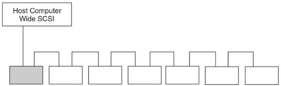
This drive uses a Wide SCSI interface. The following shows a typical system configuration.
flowchart
graph TD
    A["Host Computer Wide SCSI"] --> B["Gray Block"]
    A --> C["White Block"]
    A --> D["White Block"]
    A --> E["White Block"]
    A --> F["White Block"]
    A --> G["White Block"]
    A --> H["White Block"]
Peripheral DevicesAlTe1040/AlTe1040A/or
AlTe520/AlTe520V/
AlTe390/AlTe390V/
AlTe260/AlTe260V/
AlTe130/AlTe130V/
AlTe90/AlTe90V
Example connection to the host computer and other peripheral devices
Part Names and Functions
Front Panel
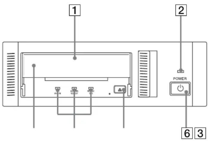
1 AIT Data Cartridge Receptacle
See page 24 to 25 for information on inserting and removing a AIT data cartridge.
2 POWER Indicator
Lights while the drive is on.
3 Dust Cover
Prevents dust from entering the data cartridge receptacle. Keep this cover closed when not inserting or removing data cartridges.
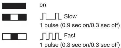
4 LED Indication for Drive Status
The LED indicators are defined as follows.
| LED | |||
| TAPE CLEANING REPLACE MOTION REQUEST TAPE | Sense | ||
| Independent | Independent Tape Loaded | ||
| Independent | Independent | Tape Access in Progress (write/read) | |
| Independent | Independent Tape Access in Progress (others) | ||
| Independent | Cleaning is requested | ||
| Independent | Cleaning is Not Completed | ||
| Independent | Independent Media | curred | |
| H/W Error Occurred | |||
5 EJECT Button
Push to remove a data cartridge from the drive.
6 POWER Switch
Press to turn the drive on or off.
Rear Panel
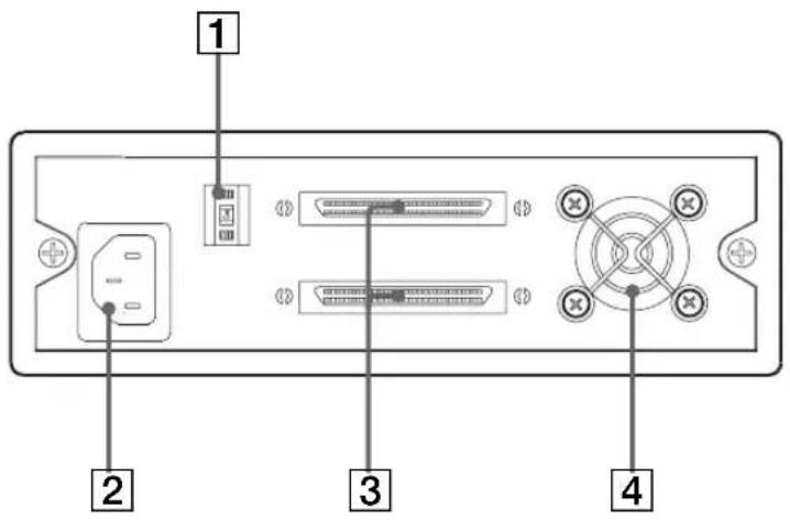
1 Rotary Selector Switch
SCSI ID selector.
② AC IN Connector
Connect the supplied power cable here.
3 SCSI Connector
Connects to the SCSI interface of the host computer or peripheral device via a Wide SCSI cable.
4 Cooling Fan
Part 2. Preparation
After you confirm that you have all of the required accessories for your installation, connect the drive to the host computer, and select the SCSI ID with the rotary switch on the rear panel.
Supplied Items
When you first open the box, make sure it contains the following items. Contact your supplier if anything is missing or broken.
- AIT Drive Unit
- Operating Instructions/Device Driver (CD-ROM)
- Quick Start Guide
- TapeCopy (CD-ROM)
- Terminator
- AIT data cartridge
- Cleaning cartridge
Notes
- In addition to the above items, the package may also include a power cord, SCSI cable, documentation, and application CD.
- The supplied items are listed on the bundled goods list affixed to the box.
Interconnections
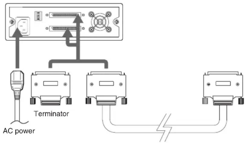
A single Wide SCSI bus allows connection of up to 15 peripheral SCSI devices.
Use a commercially available SCSI cable appropriate to the peripheral device for connections.
This drive uses a 68-pin half-pitch connector.
Precautions
- Switch off the host computer and peripherals before connecting the SCSI cable.
- Make sure the SCSI connectors are pressed tightly together.
- If this unit is the last (or only) device on the SCSI bus, make sure to connect a terminator to the appropriate unused SCSI connector. Using an incompatible terminator may damage the unit.
- During LVD SCSI connections, make sure that the total length of the cable(s) connecting the host computer and the last device on the SCSI bus is no longer than 12 meters (39 feet). (During single-end SCSI connections, make sure that the total length of the SCSI cable(s) is no longer than 1.5 meters (5 feet).)
SCSI ID Setting
The SCSI ID is set by the rotary switch on the rear panel. Press the + or - buttons to move the number up or down, respectively.
As shipped from the factory, the SCSI ID is set to 5. Press the switch buttons, if necessary, to select the SCSI ID number you require. Because the host adapter ID is usually set to 7, select some other value for the SCSI ID setting.
Precautions
- The SCSI ID must be different from IDs of the other peripherals on the SCSI bus.
- When shipped from the factory, SCSI parity is enabled and Term power is ON. Be sure to connect a terminator to the SCSI bus before use.
- Before changing the SCSI ID setting, be sure to turn off the power with the POWER switch on the front panel.
Option Switches (DIP Switch)
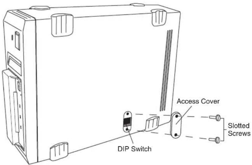
Remove the two slotted screws by using a slotted screwdriver. Remove the access cover to change the DIP switch settings. (Refer to the following figure for details changing the DIP switch settings.)
After changing the DIP switch settings, replace access cover and tighten the two slotted screws using a slotted screwdriver.
CAUTION
Before removing the access cover to change DIP switch settings on the drive, turn off the computer and disconnect the power cord from the unit. Once the DIP switch settings have been changed, replace the access cover using the two original slotted screws provided.
DIP Switch Positions
(for the AITe1040, AITe1040V, AITe520, AITe520V, AITe390, and AITe390V Drives)
Default
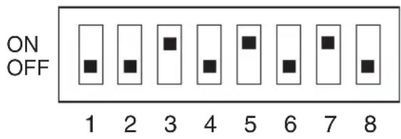
1 DR (Disaster Recovery)
Mode (OFF)
2 Emulation Mode (OFF)
3 AIT Library Interface Mode (ON)
4 Reserved (OFF)
5 Terminator Power (ON)
6 Periodic Cleaning Req (OFF)
7 DC Control (1) (ON)
8 DC Control (2) (OFF)
Emulation Mode\*
To enable Emulation Mode, set DIP switch 2 [Emulation Mode] to ON.
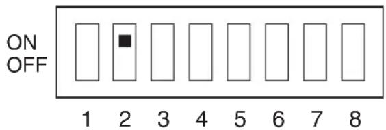
* Emulation Mode for the AITe1040/AITe1040V drives return the following as the Product Identification field of the Inquiry command.
SDX-900V
* Emulation Mode for the AITe520/AITe520V drives return the following as the Product Identification field of the Inquiry command.
SDX-700C
* Emulation Mode for the AITe390/AITe390V drives return the following as the Product Identification field of the Inquiry command.
SDX-700C
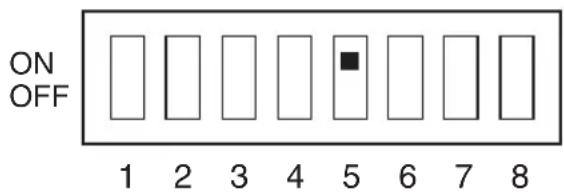
Terminator Power
To enable terminator power, set DIP switch 5 [Terminator Power] to ON.
Periodic Cleaning Request Mode
To enable Periodic Cleaning Request Mode, set DIP switch 6 [Periodic Cleaning Req] to ON.
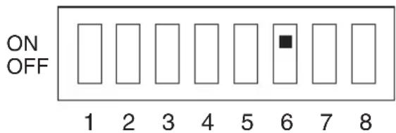
The “CLEANING REQUEST” LED on the front panel lights after every 100 hours of operation.
When this LED lights, clean the drive with a cleaning cartridge.
Note
To maintain the drive in optimum condition in environments affected by dust and other contaminants, we recommend keeping cleaning requests enabled.
Data Compression Control
Data compression can be selected by DIP switches.
Data compression is enabled when DIP switch 7 [DC Control (1)] is ON.
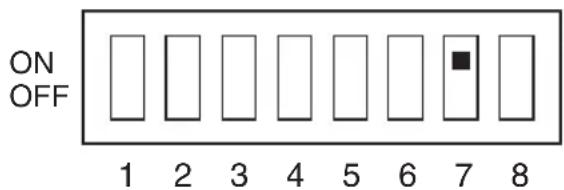
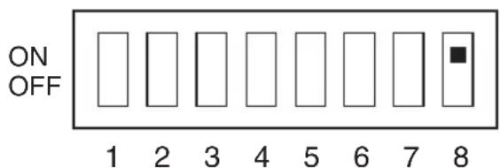
Control by host can be disabled when DIP switch 8 [DC Control (2)] is ON.
DIP Switch Positions
(for the AITe260, AITe260V, AITe130, AITe130V, AITe90, and AITe90V Drives)
Default
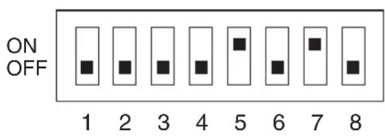
1 Drive Mode (OFF)
2 Drive Mode (OFF)
3 Drive Mode (OFF)
4 Drive Mode (OFF)
5 Terminator Power (ON)
6 Periodic Cleaning Req (OFF)
7 DC Control (1) (ON)
8 DC Control (2) (OFF)
Emulation Mode\*
To enable Emulation Mode, set DIP switches 1 to 4 [Drive Mode] to ON.
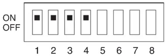
* Emulation Mode for the AITe260/AITe260V drives return the following as the Product Identification field of the Inquiry command.
SDX-700C
* Emulation Mode for the AITe130/AITe130V drives return the following as the Product Identification field of the Inquiry command.
SDX-500C
* Emulation Mode for the AITe90/AITe90V drives return the following as the Product Identification field of the Inquiry command.
SDX-400C
Terminator Power
To enable terminator power, set DIP switch 5 [Terminator Power] to ON.
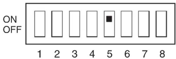
Periodic Cleaning Request Mode
To enable Periodic Cleaning Request Mode, set DIP switch 6 [Periodic Cleaning Req] to ON.
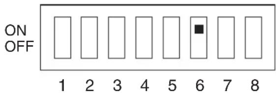
The “CLEANING REQUEST” LED on the front panel lights after every 100 hours of operation.
When this LED lights, clean the drive with a cleaning cartridge.
Note
To maintain the drive in optimum condition in environments affected by dust and other contaminants, we recommend keeping cleaning requests enabled.
Data Compression Control
Data compression can be selected by DIP switches.
Data compression is enabled when DIP switch 7 [DC Control (1)] is ON.
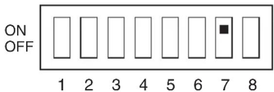
Control by host can be disabled when DIP switch 8 [DC Control (2)] is ON.
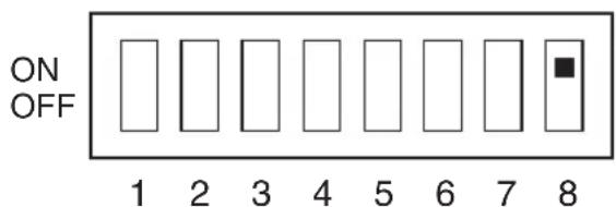
Part 3. Operation
This section describes how to use the AIT drive, and how to handle data cartridges.
How To Use the AIT Drive
1 Press the POWER switch on the front panel. The POWER indicator should light, and the TAPE MOTION, CLEANING REQUEST, and REPLACE TAPE indicators should blink as the self-test is performed.
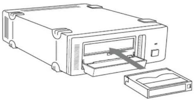
2 When the three indicators stop blinking, open the dust cover and insert a data cartridge as shown below. The TAPE MOTION indicator lights.
natural_image
Line drawing of a portable electronic device with an open drawer and a separate storage tray (no text or symbols)3 Computer software controls the reading and writing of tapes. While reading or writing, the TAPE MOTION indicator blinks.
4 Close the dust cover.
Cartridge Removal
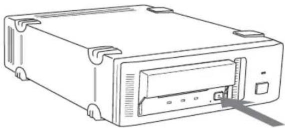
1 Press the EJECT button.
2 Open the dust cover. The cartridge is ejected automatically.
natural_image
Line drawing of a rectangular electronic device with a central drive and ports (no text or symbols)Caution
Do not push the EJECT button while the TAPE MOTION indicator is blinking. To do so may destroy data on the tape.
3 Remove the cartridge from the receptacle, and then close the dust cover.
Attaching the Dust Cover
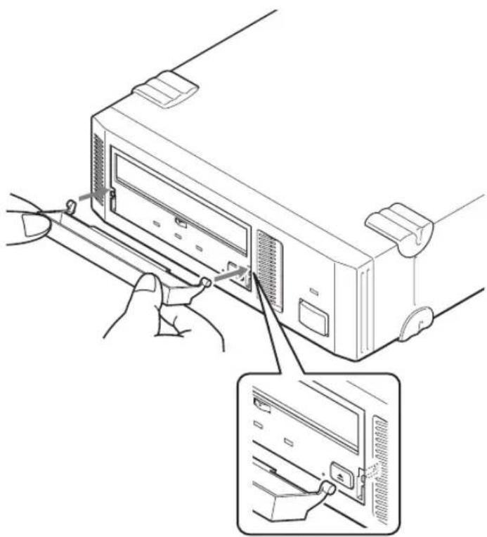
If the dust cover comes loose, attach it as described below.
Note
We recommend that you use the drive with the dust cover.
1 Align the dust cover's hinge clips (one on each side) with the pins of the drive bezel.
- The dust cover should be positioned so that the magnets* on the cover's back face the drive bezel.
* This magnet does not affect the tape of the cartridge. - Holding the dust cover at an angle as shown in the figure below, set the hinge clips on top of the bezel pins, positioning them so that they bracket the pins.
natural_image
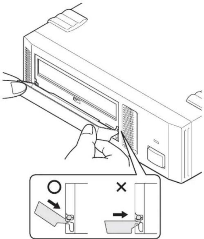
Line drawing of a computer monitor with cable and ports, showing a close-up of the internal panel (no text or symbols)2 Press down at an angle on each side in turn until you hear the hinge clips click into place.
Caution
Do not press the dust cover in horizontally from the front. Doing so could cause the dust cover to break.
3 Close the dust cover.
This completes attachment of the dust cover.
WORM Function
The AITe1040, AITe1040V, AITe520, AITe520V, AITe260, AITe260V, AITe130, and AITe130V drives support the WORM function. This explains the WORM function.
What is "WORM"?
“WORM” is an acronym for “Write Once Read Many”, a function that allows data to be written to the same place on a tape only once, but permits that data to be read from the tape for any number of times. The AITe1040,
AITe1040V, AITe520, AITe520V, AITe260, AITe260V, AITe130, and AITe130V drives support WORM cartridges. When a WORM cartridge is used with an application that supports the WORM function, data that has been written to a tape can not be accidentally deleted or overwritten.
A WORM drive operates in the same manner as a non-WORM drive when used with a non-WORM cartridge (henceforth referred to as “regular cartridge”).
The operation of a WORM drive and a non-WORM drive differs according to the type of cartridge that is being used.
| Tape Drive Cartridge | ||
| Regular Cartridge WORM (without WORM logo) (with WORM logo) | Cartridge | |
| Non-WORM drive Read/Write Enabled Waiting for Eject | ||
| WORM drive Read/Write Enabled Read/ | Append-Write Enabled | |
WORM Cartridges
WORM cartridges can be distinguished from regular cartridges by their WORM logo and red shutters.
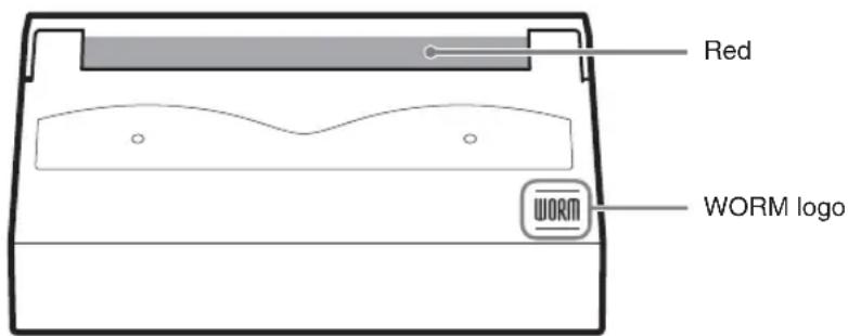
AIT-5 WORM cartridge: SDX5-400W
AIT-4 WORM cartridge: SDX4-200W
AIT-3 WORM cartridge: SDX3-100W
AIT-2 WORM cartridge: SDX2-50W
How to Write Data onto a WORM Cartridge
As with a regular cartridge, there is no limit on how many times data can be read from a WORM cartridge. When writing data to a WORM cartridge, the data cannot be written to a portion of the tape that data has already been written.
When writing data onto a WORM cartridge, it is appended after data that has already been written onto the cartridge. Accordingly, you must move to the EOD area before writing data onto the cartridge.
SCSI Commands Supported by the WORM Drive
The WORM drives support the same SCSI commands that are supported by non-WORM drives. However, if an attempt is made to write to a portion of a tape where data has already been written, the following error information is returned: “Sense Key = 07, ASC = 27h, ASCQ = 00: Persistent Write Protect” or “Sense Key = 03, ASC = 27h, ASCQ = 04: Write Position Error.”
Notes
- Sony cannot accept liability for data written onto a WORM cartridge that is lost as a result of using this unit.
- Sony accepts no responsibility for any financial damages, lost profits, or claims made by third parties arising from the use of this product.
Taking Care of the Drive
Safety Considerations
Power
- Be sure to use only 100 V - 240 V AC.
- Avoid plugging into the same outlet as high-current equipment like copiers or shredders.
■ Power Cable Precautions
- Do not crush the cable or place heavy items on it. If the cable insulation appears worn or broken, do not use the cable.
- Always unplug the cable by holding the plug. Never pull the cable itself, as it will break.
- If the drive is not being used for a long time, unplug the cable from the outlet.
Avoiding Damage
■ Avoid shock and vibration
Intense shock, such as from dropping the drive, will damage it.
■ Environmental considerations
Do not store or use the drive in locations subject to:
• high humidity • excessive dust
• high temperature • intense vibration
- direct sunlight • sudden changes in temperature
■ Proper ventilation
To avoid overheating, install the drive where it will have free air circulation around the case, and do not cover it during operation. The drive can malfunction if the internal temperature rises too high.
■ Avoid sudden changes in temperature
If the drive is moved from a cool place to a warm place, or if the room temperature suddenly rises, moisture may condense inside the case. After a sudden change in temperature, turn off the drive and wait at least one hour before turning it on again.
Inserting a cartridge with condensation inside the drive can damage the drive or the tape. Immediately remove cartridges in the drive if there is a possibility that there is condensation inside.
Leaving the drive on without inserting cartridges, moreover, will quickly evaporate any condensation.
■ Abnormal occurrences
If the drive behaves abnormally, or if it begins to smell or smoke, immediately unplug it from the wall outlet and contact your supplier for assistance.
■ Cabinet cleaning
Wipe the cabinet with a soft dry cloth. For heavy dirt, wipe with a soft cloth moistened with a gentle liquid soap, then wipe again with a soft dry cloth. Do not use alcohol, paint thinner, bug sprays, or other volatile solvents, as they can damage the finish.
Taking Care of Cartridges
Use Precautions
- Avoid heavy vibration and dropping.
- The shutter on the face of the cartridge is opened automatically when it is inserted into the drive. Do not open the shutter by hand, as touching the tape may damage it.
- The cartridge was carefully aligned during assembly at the factory. Please do not try to open it or take it apart.
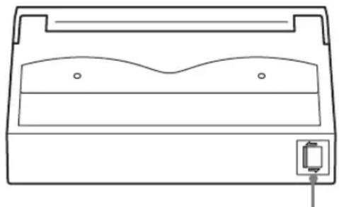
- The write-protect switch on the face of the cartridge prevents the tape from being written to or accidentally erased. If you do not need to write to the tape, move this switch to the write-protect position (in the direction of the arrow).
natural_image
Line drawing of a rectangular electronic device with a base and top component, no text or symbols present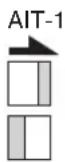
AIT-5 AIT-4 AIT-3 Ex AIT-3 AIT-2 Turbo AIT-2
AIT-1 Turbo AIT-E Turbo
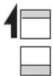
Using your fingernail, push the switch in the direction of the arrow to protect the tape from writing or accidental erasure.
Return the switch to its original position to re-enable writing.
- In case of a sudden change in temperature, condensation may interfere with reading and writing to a tape.
- Avoid unnecessary insertion and removal of cartridges if you do not need to write or read a tape.
- When finished using the drive, remove the cartridge.
Storage Precautions
- Keep cartridges in their cases when not in the drive.
- Avoid storing cartridges in dusty places, in direct sunlight, near heaters or air conditioners, or, in humid locations.
- Do not place cartridges on the dashboard or in a storage tray in a car.
Cleaning
To keep the AIT drive in top condition, clean the drive unit as needed using a cleaning cartridge with the AIT logo. When the drive unit needs cleaning, the CLEANING REQUEST indicator lights. (For the AITe1040, AITe1040V, AITe520, AITe520V, AITe390, and AITe390V, use the AITe1040, AITe1040V, AITe520, AITe520V, AITe390, and AITe390V cleaning cartridge respectively.)
Use the cleaning cartridge made exclusively for each model.
| Cleaning cartridge to use | |
| AITe1040, AITe1040V SDX5-CL | |
| AITe520, AITe520V SDX4-CL, SDX4-CLL | |
| AITc390, AITc390V SDX3X-CL | |
| AITc260, AITc260V, AITe130, AITe130V, SDX1-CL AITe90, AITe90V | CL |
How To Clean
1 Load the cleaning cartridge into the AIT drive.
Cleaning starts automatically.
2 Cleaning takes about 15 seconds and the cartridge is automatically ejected when finished. (AITe260, AITe260V, AITe130, AITe130V, AITe90, AITe90V)
Cleaning takes from a few seconds to a minute for the AITe1040, AITe1040V, AITe520, AITe520V, AITe390, and AITe390V*, and the cartridge is automatically ejected when finished.
* The cleaning time varies depending on the condition of the drive (AITe1040, AITe1040V, AITe520, AITe520V, AITe390, AITe390V).
Notice
Do not rewind the cleaning cartridge and reuse it. When you reach the end of the cartridge, dispose it and buy a new cleaning cartridge with the AIT logo.
Specifications (AlTe1040/AlTe1040V)
Performance
Storage Capacity 1,040GB compressed (with SDX5-400C) * 400 GB uncompressed (with SDX5-400C)
Bit Error Rate less than 10 -17
Data Transfer Rate 24 MB/s uncompressed
62.4 MB/s compressed*
Burst Data Transfer Rate 12 MB/s maximum, asynchronous
(SCSI) 160 MB/s maximum, synchronous
Initialize Time less than 5 seconds
Load Time average of 14 seconds **
Unload Time average of 24 seconds **
Rewind Time average of 115 seconds (with SDX5-400C)
■ Operating Environment
| Operating Temperature: 10 to 35 °C (ΔT<10 °C / h) |
| (50 to 95 °F (ΔT<18 °F / h)) |
| Humidity: 30 to 80% (no condensing) |
| Maximum wet bulb temperature: 26 °C (78.8 °F) |
| Non-operating Temperature: -40 to 70 °C (ΔT<20 °C / h) |
| (-40 to 158 °F (ΔT<36 °F / h)) |
| Humidity: 10 to 90% (ΔRH<30% / h) |
| Maximum wet bulb temperature: 45 °C (113 °F) |
■ Power Supply & Miscellaneous
Power Supply 100 V to 240 V AC, 50/60 Hz
1.2 A
Case Dimensions 198× 64.5× 246mm (W× H× D)
(excluding protruding parts)
Weight 2.4 kg
Specifications may be subject to change, in the interest of technological improvement, without notice or obligation.
Specifications (AlTe520/AlTe520V)
■ Performance
Storage Capacity 520 GB compressed (with SDX4-200C) * 200 GB uncompressed (with SDX4-200C) Bit Error Rate less than 10 -17
Data Transfer Rate 24 MB/s uncompressed 62.4 MB/s compressed*
Burst Data Transfer Rate 12 MB/s maximum, asynchronous
(SCSI) 160 MB/s maximum, synchronous
Initialize Time less than 5 seconds
Load Time average of 14 seconds
Unload Time average of 24 seconds
Rewind Time average of 115 seconds (with SDX4-200C)
■ Operating Environment
Operating Temperature: 10 to 35 °C ( T<10 ^/h ) (50 to 95 °F ( T<18 ^/h )) Humidity: 30 to 80% (no condensing) Maximum wet bulb temperature: 26 °C (78.8 °F)
Non-operating Temperature: -40 to 70 °C ( T<20 ^/h ) ( -40 to 158 ^ ( T<36 ^/h) )
Humidity: 10 to 90% ( RH < 30% / h)
Maximum wet bulb temperature: 45 °C (113 °F)
■ Power Supply & Miscellaneous
Power Supply 100 V to 240 V AC, 50/60 Hz 1.2 A Case Dimensions 198 × 64.5 × 246 mm (W × H × D) (excluding protruding parts) Weight 2.4 kg
Specifications may be subject to change, in the interest of technological improvement, without notice or obligation.
Specifications (AlTe390/AlTe390V)
■ Performance
| Storage Capacity 390 GB compressed (with SDX3X-150C) | * |
| 150 GB uncompressed (with SDX3X-150C) | |
| Bit Error Rate less than 10 | -17 |
| Data Transfer Rate 18 MB/s uncompressed | |
| 46.8 MB/s compressed* | |
| Burst Data Transfer Rate 12 MB/s maximum, asynchronous(SCSI) 160 MB/s maximum, synchronous | |
| Initialize Time less than 5 seconds | |
| Load Time average of 14 seconds | ** |
| Unload Time average of 24 seconds | ** |
| Rewind Time average of 115 seconds(with SDX3X-150C)** | |
■ Operating Environment
| Operating Temperature: 10 to 35 °C (ΔT<10 °C / h) |
| (50 to 95 °F (ΔT<18 °F / h)) |
| Humidity: 30 to 80% (no condensing) |
| Maximum wet bulb temperature: 26 °C (78.8 °F) |
| Non-operating Temperature: -40 to 70 °C (ΔT<20 °C / h) |
| (-40 to 158 °F (ΔT<36 °F / h)) |
| Humidity: 10 to 90% (ΔRH<30% / h) |
| Maximum wet bulb temperature: 45 °C (113 °F) |
■ Power Supply & Miscellaneous
| Power Supply | 100 V to 240 V AC, 50/60 Hz |
| 1.2 A | |
| Case Dimensions | 198 × 64.5 × 246 mm (W × H × D) |
| (excluding protruding parts) | |
| Weight | 2.4 kg |
Specifications may be subject to change, in the interest of technological improvement, without notice or obligation.
Specifications (AlTe260/AlTe260V)
■ Performance
Storage Capacity 260 GB compressed (with SDX3-100C) * 100 GB uncompressed (with SDX3-100C) Bit Error Rate less than 10 -17
Data Transfer Rate 12 MB/s uncompressed 31.2 MB/s compressed*
Burst Data Transfer Rate 12 MB/s maximum, asynchronous
(SCSI) 160 MB/s maximum, synchronous
Initialize Time less than 5 seconds
Load Time average of 14 seconds
Unload Time average of 24 seconds
Rewind Time average of 105 seconds (with SDX3-100C)
■ Operating Environment
Operating Temperature: 10 to 35 °C ( T<10 ^/h ) (50 to 95 °F ( T<18 ^/h )) Humidity: 30 to 80% (no condensing) Maximum wet bulb temperature: 26 °C (78.8 °F)
Non-operating Temperature: -40 to 70 °C ( T<20 ^/h ) ( -40 to 158 ^ ( T<36 ^/h) )
Humidity: 10 to 90% ( RH < 30% / h)
Maximum wet bulb temperature: 45 °C (113 °F)
■ Power Supply & Miscellaneous
Power Supply 100 V to 240 V AC, 50/60 Hz 1.2 A Case Dimensions 198 × 64.5 × 246 mm (W × H × D) (excluding protruding parts) Weight 2.4 kg
Specifications may be subject to change, in the interest of technological improvement, without notice or obligation.
Specifications (AlTe130/AlTe130V)
■ Performance
Storage Capacity 130 GB compressed (with SDX2-50C) * 50 GB uncompressed (with SDX2-50C) Bit Error Rate less than 10 -17
Data Transfer Rate 6 MB/s uncompressed 15.6 MB/s compressed*
Burst Data Transfer Rate 12 MB/s maximum, asynchronous (SCSI) 40 MB/s maximum, synchronous Initialize Time less than 5 seconds Load Time average of 14 seconds ** Unload Time average of 20 seconds ** Rewind Time average of 105 seconds (with SDX2-50C)
■ Operating Environment
Operating Temperature: 10 to 35 °C ( T<10 ^/h ) (50 to 95 °F ( T<18 ^/h )) Humidity: 30 to 80% (no condensing) Maximum wet bulb temperature: 26 °C (78.8 °F) Non-operating Temperature: -40 to 70 °C ( T<20 ^/h ) (-40 to 158 °F ( T<36 ^/h )) Humidity: 10 to 90% ( RH<30% /h ) Maximum wet bulb temperature: 45 °C (113 °F)
■ Power Supply & Miscellaneous
Power Supply 100 V to 240 V AC, 50/60 Hz 1.2 A Case Dimensions 198 × 64.5 × 246 mm (W × H × D) (excluding protruding parts) Weight 2.4 kg
Specifications may be subject to change, in the interest of technological improvement, without notice or obligation.
Specifications (AlTe90/AlTe90V)
■ Performance
Storage Capacity 91 GB compressed (with SDX1-35C) 35 GB uncompressed (with SDX1-35C) Bit Error Rate less than 10 -17
Data Transfer Rate 4 MB/s uncompressed 10.4 MB/s compressed*
Burst Data Transfer Rate 12 MB/s maximum, asynchronous (SCSI) 40 MB/s maximum, synchronous Initialize Time less than 5 seconds Load Time average of 14 seconds ** Unload Time average of 20 seconds ** Rewind Time average of 105 seconds (with SDX1-35C)
■ Operating Environment
Operating Temperature: 10 to 35 °C ( T<10 ^/h ) (50 to 95 °F ( T<18 ^/h )) Humidity: 30 to 80% (no condensing) Maximum wet bulb temperature: 26 °C (78.8 °F) Non-operating Temperature: -40 to 70 °C ( T<20 ^/h ) (-40 to 158 °F ( T<36 ^/h )) Humidity: 10 to 90% ( RH<30% /h ) Maximum wet bulb temperature: 45 °C (113 °F)
■ Power Supply & Miscellaneous
Power Supply 100 V to 240 V AC, 50/60 Hz 1.2 A Case Dimensions 198 × 64.5 × 246 mm (W × H × D) (excluding protruding parts) Weight 2.4 kg
Specifications may be subject to change, in the interest of technological improvement, without notice or obligation.
Sony Contacts
For further information, please contact:
Sony Electronics Inc., Tape Storage Solutions (USA)
URL: http://www.storagebysony.com
Sony of Canada Ltd., AV/IT Marketing Group
Computer Peripherals Product Marketing
115 Gordon Baker Road Toronto, Ontario, M2H 3R6 Canada
TEL: (416) 499-1414 or (1) 800-961-7669
FAX: (416) 499-8541
Sony Business Europe
URL: http://www.sonyisstorage.com/
Electronics Devices Marketing (Singapore)
(A division company of Sony Electronics (S) Pte. Ltd.)
Enterprise Storage Solutions Dept.
2 International Business Park, #01-10 Tower One, The Strategy,
Singapore 609930
TEL: 65-6544-8000 FAX: 65-6544-7390
Sony Corporation of Hong Kong Ltd.
Computer Peripheral Sales & Marketing Division
Electronic Devices Marketing Hong Kong
45/F, The Lee Gardens, 33 Hysan Avenue, Causeway Bay, Hong Kong
TEL: (852) 2909-1008 FAX: (852) 2909-2001
Sony Corporation of Hong Kong Ltd. Beijing Rep. Office
Computer Peripheral Div.
Full Link Plaza Tower A 11/F., No.18 Chaoyangmenwai Ave., Beijing
100020 P.R.C.
TEL: 86-10-6588-0633 FAX: 86-10-6588-0855
URL: http://www.sony.com.cn/ed/cp/ait/
Sony Corporation of Hong Kong Ltd.,
Electronic Devices Marketing Hong Kong
Computer Peripherals Sales & Marketing Div.
8/F, One Corporate Avenue, 222 Hu Bin Road. Luwan District,
Shanghai. P.R.C. Postcode 200021
TEL: 86-21-6121-6878
URL: http://www.sony.com.cn/ed/cp/ait/
Sony Brasil Ltda.
Rua Inocéncio Tobias, 125, Barra Funda
São Paulo-SP, Brasil 01144-000
TEL: (55) 11-2196-9000 FAX: (55) 11-2196-9186
Sony Australia Limited
33-39 Talavera Rd.
NORTH RYDE, NSW 2113
TEL: 1300-13-7669 FAX: 02-9870-5864
e-mail: CIC-customerissues@ap.sony.com
Sony New Zealand
Akoranga Business Park
NORTH SHORE, AUCKLAND
TEL: 0800-76-6969 FAX: 09-308-9300
e-mail: CIC-customerissues@ap.sony.com
Sony Chile Ltda
Av. Kennedy 8017, Las Condes, Santiago, Chile
TEL: (02) 210-6000 FAX: (02) 210-5417
Sony Taiwan Limited
Optical Devices Storage Dept. Data Storage Section
5F, 145 Changchun Road, Taipei 104, Taiwan
TEL: 886-2-2522-7920 FAX: 886-2-2522-2153
Sony Korea Corporation EDMK CP Sales & Marketing Team
34F, ASEM Tower, World Trade Center, 159-1, Samsung-Dong,
Kangnam-Ku, Seoul, 135-798, Korea
TEL: 82-2-6001-4249 FAX: 82-2-6001-4115
URL: http://www.sony.co.kr/cp/
Sony Gulf FZE Computer Display & Peripheral Div.
P.O.BOX 16871, Jebel Ali, Dubai, U.A.E.
TEL: 971-4-8815488 or 8816912 FAX: 971-4-8817210 or 8816259
Sony Marketing of Japan
Business Solution Dept. Server Solution Marketing Section
URL: http://www.sony.co.jp/STORAGE
- StorStation
- Safety Regulations
- Owner's Record
- Information
- WARNING
- To reduce the risk of fire or electric shock, do not expose this apparatus to rain or moisture.
- To avoid electrical shock, do not open the cabinet.
- Refer servicing to qualified personnel only.
- Model No. for Regulatory Compliance
- For the customers in the USA
- CAUTION
- ACHTUNG
- HINWEIS
- ATTENTION
- AUFMERKSAMKEIT
- European Union Restriction of Hazardous Substances Directive compliant.
- DECLARATION OF CONFORMITY
- USE
- For the unit with a three-wire grounding type ac plug:
- AC Power cord:
- INSTALLATION
- SERVICE
- Table of Contents
- How To Use This Guide
- About AIT Drives
- Features
- Compatible Data Cartridges
- System Components
- Part Names and Functions
- Front Panel
- Rear Panel
- Part 2. Preparation
- Supplied Items
- Notes
- Interconnections
- Precautions
- SCSI ID Setting
- Option Switches (DIP Switch)
- DIP Switch Positions
- Emulation Mode\*
- Terminator Power
- Periodic Cleaning Request Mode
- Note
- Data Compression Control
- (for the AITe260, AITe260V, AITe130, AITe130V, AITe90, and AITe90V Drives)
- Part 3. Operation
- How To Use the AIT Drive
- Cartridge Removal
- Attaching the Dust Cover
- WORM Function
- What is "WORM"?
- WORM Cartridges
- How to Write Data onto a WORM Cartridge
- SCSI Commands Supported by the WORM Drive
- Taking Care of the Drive
- Safety Considerations
- Power
- ■ Power Cable Precautions
- Avoiding Damage
- ■ Avoid shock and vibration
- ■ Environmental considerations
- ■ Proper ventilation
- ■ Avoid sudden changes in temperature
- ■ Abnormal occurrences
- ■ Cabinet cleaning
- Taking Care of Cartridges
- Use Precautions
- Storage Precautions
- Cleaning
- How To Clean
- Notice
- Specifications (AlTe1040/AlTe1040V)
- Performance
- ■ Operating Environment
- ■ Power Supply & Miscellaneous
- Specifications (AlTe520/AlTe520V)
- ■ Performance
- Specifications (AlTe390/AlTe390V)
- Specifications (AlTe260/AlTe260V)
- Specifications (AlTe130/AlTe130V)
- Specifications (AlTe90/AlTe90V)
- Sony Contacts
- For further information, please contact:
- Sony Australia Limited
- Sony New Zealand
- Sony Chile Ltda
- Sony Taiwan Limited
- Optical Devices Storage Dept. Data Storage Section
- Sony Korea Corporation EDMK CP Sales & Marketing Team
- Sony Gulf FZE Computer Display & Peripheral Div.
- Sony Marketing of Japan
Brand : SONY
Model : StorStation AITe520V
Category : Data Storage