
900 (1982) - Car SAAB - Free user manual and instructions
Find the device manual for free 900 (1982) SAAB in PDF.


| Product Type | Passenger car |
| Brand | Saab |
| Model | 900 |
| Model Year | 1982 |
| Body Style | 2-door coupe, 4-door sedan (approx) |
| Engine Type | 2.0L inline-4 gasoline |
| Power Output | Approx 100 hp |
| Transmission | 4-speed manual (standard) |
| Drive Type | Front-wheel drive |
| Seating Capacity | 5 |
| Fuel Type | Gasoline (unleaded) |
| Fuel Capacity | Approx 60 liters |
| Dimensions (L x W x H) | Approx 4.6 m x 1.7 m x 1.4 m |
| Weight (kerb) | Approx 1200 kg |
| Main Features | Heater, defroster, AM/FM radio, manual windows |
| Maintenance | Oil change every 5,000 km, timing belt every 60,000 km |
| Safety Equipment | Seat belts, collapsible steering column, impact-absorbing bumpers |
| Spare Parts Availability | Available through aftermarket and specialist suppliers |
| Repairability | Moderate; many parts shared with other Saab models |
Frequently Asked Questions - 900 (1982) SAAB
User questions about 900 (1982) SAAB
0 question about this device. Answer the ones you know or ask your own.
Ask a new question about this device
Download the instructions for your Car in PDF format for free! Find your manual 900 (1982) - SAAB and take your electronic device back in hand. On this page are published all the documents necessary for the use of your device. 900 (1982) by SAAB.
USER MANUAL 900 (1982) SAAB
natural_image
Front view of a modern sedan (no visible text or symbols)SAAB 900
1982 OWNER'S MANUAL
SERVICE STATION INFORMATION
| To open hood: | Pull hood release lever (located under left side of instrument panel).Press the front edge of hood down slightly and release safety catch. Allow front of hood to rise and move forward, then tilt entire hood forward. To close hood tilt rearward and reverse the above procedure.(CLOSE SLOWLY UNTIL SAFETY CATCH ENGAGES, THEN PUSH FIRMLY TO LATCH.) |
| To remove ignition key: | Engage Reverse (manual) or Park (automatic) and turn key to “L” (lock). Key is located on center console. |
| Recommended fuel:Lubricants: | Catalyst-Equipped Engine—Unleaded, minimum octane rating = 87.Engine Oil: Hot weather— SAE 10W40Normal — SAE 10W30, 10W40Below 0°F — SAE 5W20Transmission: Manual — SAE 10W30, API Service SEAutomatic — Type “F”, M2C33F (Do not use Dexron ATF)Final Drive (Automatic): EP SAE 80, API-GL-4 or GL-5 |
| Coolant: | Ethylene Glycol with aluminum corrosion protection properties mixed with clean fresh water (minimum 50% glycol in mix year round). |
| Power Steering: | Use only “GM Specification Power Steering Fluid” (GM 9985010, Texaco TL4834 or equivalent). Do not use ATF. |
| Tires: | Pressures: See Specifications Section page 38. DO NOT TIGHTEN WHEELNUTS WITH AN IMPACT WRENCH. |
| Tune-up information:Towing disabled vehicle: | See Vehicle Emission Control Information label, left front inner fender.See recommendations on page 55. |
| CAUTION: The fuel injection system should be adjusted or disassembled only with the proper tools and according to prescribed procedures and only by qualified persons skilled in Bosch CIS servicing. Fuel lines must never be cut or spliced and all connections must be properly torqued on reassembly. Tampering with the Continuous Injection System or Turbo-charger (if equipped) may void warranty coverage of affected components.When welding on vehicle, disconnect the alternator. Avoid the plastic fuel tank and lines and all flammable materials. | |
CONTENTS
| Section | Description | Page | |
| I. | Operating InstructionsA. ENTRY AND SECURITYB. ACCOMMODATIONS AND SAFETYC. CONTROLS AND INSTRUMENTSD. STARTING AND DRIVINGE. SPECIAL INSTRUCTIONS—TURBO MODELS | 2471620 | I. |
| II. | Technical InformationA. POWER UNITB. ELECTRICAL SYSTEMC. STEERING AND BRAKESD. WHEELS AND TIRESE. SPECIFICATIONSF. VEHICLE IDENTIFICATIONG. CONSUMER INFORMATION | 21303334364041 | II. |
| III. | Service and MaintenanceA. SCHEDULED MAINTENANCE PROGRAM (Inc. Break-In Service)B. GENERAL INFORMATION TROUBLE SHOOTING APPEARANCE CARE & RUST PREVENTATIVE CARE OWNER ASSISTANCE TOWING PROCEDURE | 4453535555 | III. |
| IV. | Index | 59 | IV. |
I. OPERATING INSTRUCTIONS
A. Entry and Security
DOORS
Two keys are supplied with the car. Both fit the ignition switch and all locks. The serial number of the key will be found engraved on a small plastic lug on the key ring. Keep the lug and make a note of the serial number in case the key is lost.
Both front side doors have lockable outside handles.
These are locked and unlocked as follows:
To Lock: Give the key a quarter turn rearward and let it spring back to the vertical position.
To Unlock: Give the key a quarter turn forward and let it spring back to the vertical position.

All side doors are fitted with safety lock buttons with which they can be locked from the inside when closed. Lock button on the driver's door cannot be pushed down when the door is open.
The rear doors of the 4-door models are provided with safety locks to prevent the doors from being unintentionally opened from the inside by children. When the lever is in the lower position (A), the doors can be opened from both inside and out, but when the lever is in the upper position (B), the door can only be opened from the outside.

natural_image
Close-up of a mechanical component with labeled parts (no readable text or symbols)Power Door Locks (4-Door 900S, Turbo)
All door locks and trunk lock will be locked or unlocked when the driver's door is locked or unlocked. Passenger doors may be locked or unlocked independently using the key (front door) or the inside knob. The trunk lid can be unlocked separately by inserting the key in the lock and turning it clockwise until it stops (approximately 2 o'clock position). With the key in this position press the release lever to unlatch the lid. Return the key to the 12 o'clock position and remove it from the lock. The lid will be automatically locked when closed.
When the power door lock is unlocked the trunk lid may be unlocked by turning the key 14 turn counter clockwise (9 o'clock position).
REAR LID
Hatchback
The rear lid is unlatched by pressing the release lever upward. The lid is locked or unlocked with the key lock on the right. An inside hand grip is provided to assist closing.
Sedan
The rear lid is unlatched by pressing the release lever rearward. The key lock is located in the lid face directly above the release lever.
The tool kit, spare tire and jack are stowed under the luggage compartment floor.
The tool well cover can also be removed via the rubber hinge straps which snap over buttons on the underside of the cover.
LUGGAGE AND CARGO SPACE
When desired, the rear seal can be converted to extend the luggage/cargo compartment.
On the hatchback models, the parcel shell can be removed and placed on the floor in the luggage compartment. The luggage compartment door is equipped with a catch to hold the parcel shell in the raised position to facilitate loading. The shell automatically returns to its horizontal position when the door is closed.

Release the seat latch and tip the seat cushion forward standing it on edge behind the front seats.
Next, release the backrest latch and drop the backrest forward.

natural_image
Close-up of a white fabric with a small dark object on the left side (no visible text or symbols)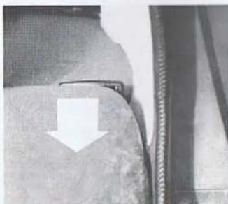
natural_image
Close-up of a fabric or leather piece with a white arrow pointing downward (no text or symbols visible)HOOD
The hood release handle is located under the instrument panel next to the inner left wheel housing.
To open the hood:
- Pull the release handle under the instrument panel. The hood will then open to the half-locked position, retained by a safety latch at the leading edge (to the right of center when facing the car).
- Press the leading edge of the hood down slightly and pull the safety catch. The hood will then spring up and can be tilted forward without effort.

natural_image
Close-up of electronic components with a white arrow pointing to a component (no visible text or symbols)To close the hood:
- Tilt hood rearward and down until the run-
- Slowly push hood rearward (with a slight upward motion) until the safety catch engages. Note: push at the center of the forward edge of the hood in order to engage the runners at the rear corners in their locking guides in the fenders.
- Press down firmly until the main lock engages securely.

B. Accommodations and Safety
SEATS
The backrest and cushion of the front seats of 900S and Turbo models have thermostat-controlled electric heating elements that warm up automatically when the ignition is switched on. The thermostat ensures that the heaters are switched on only when the seat is cold and switched off when the temperature exceeds 82^ . Both front seats are adjustable as to legroom, and the driver's seat can also be adjusted for height. The backrest angle is continuously adjustable from upright to reclining.
Legroom Adjustment
Release lever 1 (see illustration) and slide the seat to the desired position.
Backrest Angle Adjustment
The backrest angle can be infinitely adjusted between driving and resting position with knob 3.
Moving the Backrest Forward (3-Door Models)
Move lever 2 and drop the backrest forward.

Vertical Adjustment
The cushion of the driver's seat can be raised and lowered and also tilted to the front or rear. As the illustration shows, there are four possible positions.
Adjustments are made with handle 4 (see illustration) at the forward edge of the seat. Release the latch by pushing on the handle and moving it to the intermediate position. The seat can now be adjusted as follows:
- Raised seat. Move the handle back without pressing down on the seat.
- Lowered seat. Move the handle forward, pressing down on the seat.
- Seat tilted back. Move the handle back, pressing down on the seat.
- Seat tilted forward. Move the handle forward without pressing down on the seat.

Headrest Cushions
Some 900 models have removable rear headrest cushions as standard equipment. Rear cushions have a mounting post which fits into a bracket attached to the back of the rear seat backrest, when so equipped. The rear cushions must be pulled out when the seat is to be folded down.
Front seat head restraints have a vertical adjustment range of approximately 3½ inches. To raise, grasp both sides of the cushion and pull upwards. To lower, press down on the top center of the cushion. A system of detents will secure the cushion at the desired height.

SEAT BELT RESTRAINT SYSTEM
IMPORTANT! Seat belts, properly worn, reduce the risk of serious occupant injury in an accident or emergency maneuver. Belt type restraints are provided at all seating positions. Use them for your comfort and protection.
Driver and Front Seat Passenger
Each lap and shoulder restraint consists of a continuous belt, a latch stalk, and a locking retractor mechanism which allows passenger movement under normal circumstances and locks the belt in emergency deceleration situations.
To put the belt on, first grasp it near the shoulder belt guide loop and pull out a sufficient length of belt to reach the latch mechanism between the front seats. One section of the belt should now be lying low over the hips and the other over the shoulder nearest the guide loop. Position the latch tongue on the belt so that it can be inserted into the latch stalk.

natural_image
Close-up of hands using a mechanical clamp or bracket to adjust a piece of material (no visible text or symbols)Pull up on the upper portion of the belt to take up any slack in the lap portion. The retractor mechanism will automatically adjust the shoulder portion. The belt is released by pressing the red button marked PRESS(2). The retractor will return the belt to its stored position.
NOTE! Pregnant women should use the belt as described above paying special attention to applying the lap portion of the belt as low and snug over the hips as possible.
When the belts are in use the retractor mechanism is normally unlocked. This allows freedom of movement for the restrained occupant automatically. The belt locking mechanism is activated by rapid belt motion and/or sudden vehicle deceleration. The belts will lock during hard braking or when the vehicle is climbing or descending steep grades.
NOTE! On 4-door cars the belt guide loop comes fastened to the "B" pillar of the car body at the upper one of two possible positions. If the driver is short in stature and the belt lies too close to the neck, comfort may be improved by moving the guide loop downward 4 inches to the alternate mounting position on the "B" pillar. Ask your dealer to do this. Do not change the guide loop mounting point if by so doing the shoulder portion of the belt tends to slip off the driver's shoulder.
Rear Seat Passengers
Three lap belts are provided for rear seat passengers. The outboard belts are each equipped with an automatic retractor. The retractor mechanism is normally unlocked to permit freedom of movement. It will lock automatically under rapid belt motion or sudden force. The center belt must be adjusted manually.
WARNING!
- No alterations or additions should be made to this belt system.
- The webbing must not be bleached or redyed.
- Each belt is meant for one person only. The front belts must be used as a lap/shoulder restraint only.
- Holding your small child is not safe. Children under 5 years old and weighing less than 40 lbs. should be restrained in a suitable safety seat/restraint designed for that purpose. Follow seat manufacturer's instructions which are based on the size and weight of the child. Restraining a child safety seat with a 3-point belt requires a special clip to restrict belt movement and prevent the seat from tipping over. For further information on child restraint systems for your car write to: U.S. Dept. of Transportation, Washington, D.C. 20590.
- If in doubt on any matter concerning restraints or their use, please consult your dealer.
Seat Belt Reminder System
This vehicle is equipped with a seat belt reminder system as required by Federal Motor Vehicle Safety Standard 208, occupant Crash Protection. The purpose of this Standard is to reduce the number and severity of traffic accident injuries by promoting increased usage of seat belt systems. The vehicle may be started whether or not the seat belts are fastened. The audible buzzer of the seat belt reminder system is activated by the driver's seat and seat belt only.
REAR VIEW MIRRORS
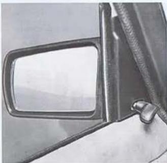
The interior rear view mirror can be deflected to avoid glare by operation of the control button underneath it. The exterior view mirrors are either manually or electrically adjustable from inside the car. The manual adjuster is a lever inside the door that is directly connected to the mirror. The electrical adjustment is done by means of four way toggle controls located on each side of the steering wheel (See diagram of controls and instruments). Exterior mirrors are anti-glare coated. To prevent scratching of this coating do not clean mirrors with sharp objects or abrasives.
NOTE: The righthand exterior mirror has a convex glass. Objects seen in the mirror are closer than they appear to be.
natural_image
Close-up of a car's side mirror and handle (no text or symbols visible)INTERIOR FITTINGS
Ashtrays
Three ashtrays are installed in the car. One is located centrally below the instrument panel and the other two in the armrests for the rear seat.
The ashtrays can be removed from the holders for emptying. To remove the front tray, grasp it at the two orange squares and pull upward. Press the ashtray down in the holder as you replace it, to ensure that it clicks into position.
Cigarette Lighter
To use the cigarette lighter, push it into the holder. It will spring back as soon as it is hot.
Glove Compartment
To open the glove compartment door, squeeze the catches on the lock. To lock, turn the key clockwise and withdraw it. To unlock the compartment, turn the key counter-clockwise. The key is the same as that for the other locks on the car.
Radio
Radio speakers are installed in the top of the instrument panel, along with wiring and antenna lead on all models. The radio, when installed, replaces the storage compartment in the center of the instrument panel.
Operational instructions are supplied with the radio provided and/or selected.
A full line of audio equipment is available from your Saab Dealer.
Sunroof
The sunroof is opened and closed by sliding the handle at the front of the panel either backwards or forwards. The roof can be opened either partially or completely. Once the handle is released, it will spring back to its central position (locking position). To close the roof, push the handle forward until the panel locks in the closed position.
C. Controls and Instruments
- Fresh air vent
- Switch, parking lights and headlights
- Clock and tachometer
- Warning lights
- Direction indicator lamp
- Speedometer, odometer and trip meter
- Combination instrument: fuel gauge, temperature gauge and pressure gauge (900 Turbo)
- Seat belt reminder light
- Switch, ventilation fan
- Temperature contro
- Air distribution control
- Switch, hazard warning flashers (cars with power windows only)
- Switch for adjusting external rear-view mirrors (900 Turbo)
- Extra switch
- Control for high/low beam and direction indicators

15A. Rheostat, control illumination
16. Horn control
17. Clock adjustment knob
18. Reset button for trip meter
19. Rheostat, instrument panel lighting
20. Control for wipers and washers
21. Switch, electric rear window defroster/Extra switch*
22. Power window switch left/Electric rear window defroster*
23. Cigarette lighter
24. Power window switch right/Hazard warning flashers*
25. Switch. Air Conditioning Compressor/Extra Switch*
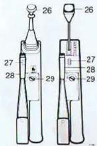
26. Gear (selector) lever
27. Switch, interior-lighting
28. Handbrake
29. Ignition switch and cear lever lock
*Switch locations vary depending on model and equipment.

WARNING AND INDICATOR LIGHTS.
Some of the warning lights will come on when the ignition is switched on before starting. These should go out once the engine is running.

Indicator Light, Electric Rear Window Defroster
This lamp will glow when the rear window defroster is switched on.

Charge Warning Light
This light will come on when the battery is not being charged. If the light comes on while you are driving, stop at the earliest convenience, switch off the engine and check the tension of the alternator drive belt.

High Beam Indicator Light
This light will glow when the headlights are switched to high beam.
PARK BRAKE
Handbrake Indicator Light
This light will glow when the handbrake is on.

Oil Pressure Warning Light (engine oil)
This light will come on if the engine oil pressure drops too low. If the light blinks or comes on while you are driving, stop the car immediately, switch off the engine and check the oil level.
BRAKE FLUID
Brake Warning Light (footbrake)
This light will come on if the level in the brake fluid reservoir drops too low. If the light comes on while you are driving, stop the car immediately and check the brake fluid level. Note: The fluid level gradually lowers as the brake pads wear. Blinking of the light may indicate that the pads are due for replacement.
EXH
Exhaust Emission System Maintenance Light
This light comes on every 30,000 miles as a reminder that components in the emission control system need maintenance. (This light does not indicate a failure).
COMBINATION INSTRUMENT
Fuel Gauge
Low Fuel Warning Light
This lamp will glow continuously when the quantity of gasoline in the fuel tank is less than approximately 2.5 U.S. gallons.
Temperature Gauge
This indicates the temperature of the engine coolant. If the needle enters the red zone repeatedly, stop as soon as possible and check the level of the coolant.
CAUTION, TURBO OWNERS! Do not operate the engine at full throttle until the needle has entered the green zone.
Pressure Gauge, 900 Turbo
The pressure gauge indicates the charging pressure in the inlet manifold. At low engine loads and during engine deceleration, a vacuum will be present in the manifold. In such cases, movement of the needle will be within the white zone. At increased loads or engine speeds, the turbo compressor will increase the charging pressure in the inlet manifold. In this case, the needle will move into the orange zone. The charging pressure will not normally be high enough to cause the needle to enter the red zone, since the engine is equipped with a regulator (wastegate) which controls the charging pressure. (There also is an overpressure safety switch.)
SPEEDOMETER, ODOMETER AND TRIP METER
The odometer records the distance in miles, and the trip meter in miles and tenths.
The reset button for the trip meter is located in the lower section of the meter. Push to reset.


TACHOMETER AND CLOCK
The tachometer indicates the speed of the engine in thousands of revolutions per minute. The needle should only be allowed to enter the broken red zone for brief periods. It must never enter the red zone. A safety device, which interrupts current to the fuel pump at 6000 rpm, is installed on the 900 Turbo.
LIGHTING SWITCHES
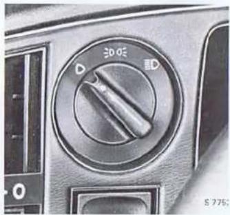
The headlight switch has three positions:

The lighting is off

Parking lights

Headlights and parking lights
Headlight Dimmer, High Beam Flasher, and Direction Indicator Control
The spring loaded lever is moved towards the steering wheel to switch from high beam or vice versa. The same action provides a warning high bleam flash when the headlights are switched off. A blue indicator light glows whenever the high beams are on. The direction indicator and cornering lights are operated by moving lever in the direction in which the steering wheel is turned. "Lane change" detents are provided.

NOTE! The headlights and parking lights are automatically turned off if the ignition key is turned to the L position. The parking lights can be operated alone, if the switch is moved to the intermediate position even if the key is removed from the ignition.
natural_image
Close-up of a car's headrest switch dial with no visible text or symbols on the dial (pure technical diagram)
Instrument Panel Lighting
The intensity of the illumination can be adjusted by means of the rheostat knob. Clockwise rotation increases brightness.
Hazard Warning
When the switch is pushed on all four direction indicator lights flash simultaneously. The warning system should only be used if the car is in a position where it is liable to endanger or obstruct other vehicles as a result of an accident, breakdown, etc. The switch flashes red when in use.
Interior Illumination
The interior illumination comprises three lights located: above the left door post, close to the rearview mirror, and beside the ignition switch. This illumination is operated by the switch on the door post lamp. The switch has three positions. The interior illumination may also be operated by means of a switch on the console between the front seats (see illustration). This switch can only be operated when the door post lamp switch is in the upper position.
NOTE! Be certain that the interior lights are switched off when parking the car.
IGNITION AND GEAR SELECTOR LOCK
The ignition and gear lock key also fits all other locks in the car. The key number is stamped into the plastic lug on the key ring. Detach and keep the lug so that the serial number is available if the key should be lost.
The ignition and gear lever lock has four positions: L—G—K—S
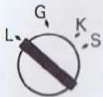
Lock Position. The gear selector lever must be placed in reverse position (manual transmission) or park (P) position (automatic transmission) before the key can be turned into the L position. In this way both the ignition and gear selector are locked simultaneously. Parking and hazard warning lamps may be activated.

Garage Position. All lights and radio can be operated. Make sure that the ignition switch is in the "G" or "L" position when the engine is not running. Otherwise the ignition coil may be damaged.

Driving Position. The entire electrical system including ignition, is operative.

Starting Position. The switch is spring loaded to return to K position when key is released. Should the engine stall or fail to start the key must be turned to the G position before the starter can again be actuated. On automatic transmission cars the starter motor can be operated ONLY when the gear selector lever is in the N or P positions.
NOTE! To ensure that the car is not left unlocked, a buzzer is activated if the left front door is opened with the key in the ignition lock.
GEAR (SELECTOR) LEVER
Manual Transmission
The gear positions are shown on the gear lever knob. To engage reverse (R), first raise the collar on the gear lever.
Automatic Transmission
The gear positions are shown on the console beside the gear selector lever.
p
R Reverse N Neutral
D)
2 } Positions for Forward Drive
1
Certain lever positions can only be selected after the button in the center of the selector knob has been depressed, to release the catch. The lever can be shifted freely to position D or N from position R, 2 or 1.

WIPER AND WASHER CONTROLS
The control lever for the windshield wipers and -asher has the following positions:
- OFF Position
- Windshield wiper, intermittent operation. The wipers will make a double sweep at intervals of a few seconds. This function is particularly useful in light drizzle, etc.
- Windshield Wipers, Low Speed
- Windshield Wipers, High Speed
- Windshield Washer: The windshield washer will operate as long as the lever is held toward the steering wheel. If the lever is pulled when in the "wipers-off" position, the wipers will automatically make a few sweeps.
Windshield Wiper and Washer Care
Inspect and clean the rubber blades of the wind-shield wipers at regular intervals. If they show signs of wear, they should be replaced. Soap and water is recommended for cleaning.
Use clean fluid for the washer and make sure that the container is free from dirt. Use suitable antifreeze in cold weather.
If the washer jets are blocked, the holes can be carefully cleaned and adjusted with a pin or smaller tool. If the jets are out of alignment, the adjustable ball nozzles can be turned to the desired position. NOTE: The driver's side jet is equipped with two ball nozzles while the passenger side has one ball nozzle.
SPEED CONTROL (OPTIONAL)
A speed control (cruise control) may be installed by your Saab dealer. (Operating instructions are provided with the unit and should be studied carefully before attempting to use the control.) This feature reduces fatigue noticeably on long highway trips. The control switch is integrated with the direction indicator level.
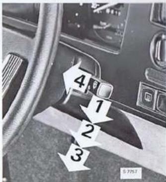
WARNING! Do not engage the speed control in dense traffic or when driving on slippery surfaces or on steep grades. Keep the control switched off when not in use.
ELECTRICALLY HEATED REAR WINDOW
The rear window defroster grid is controlled by means of a push switch near the center of the instrument panel. An indicator light glows when the heating is on. Always switch the heating off as soon as the rear window is free from ice and mist. Avoid placing heavy objects on the parcel shelf as the heating wires may easily be damaged. Do not switch on the window heating before starting the engine.
Damage to the unit may result if it is operated for a long period of time on a dry rear window. Do not use abrasive cleansers on the inside of the rear window which may damage the electrical continuity of the unit.


CLIMATE CONTROL SYSTEM Ventilation System
The Saab 900 has a sophisticated flow through ventilation system with an optional integrated air conditioner. Air enters at the right hood louver and exits at the rear quarter panel grilles. All incoming air passes through the air filter (or AC evaporator) and, except for air channels to the center panel vent, then passes through the heater core. All system controls are located in the center of the instrument panel. A schematic of the interior outlets is shown below. The three panel vents are adjustable directionally and have individual thumb wheel shut off switches (O = Off).
- Defroster outlets
- Outer panel vents (adjustable)
- Center panel vent (adjustable)
- Floor cutlets
Fresh Air Filter
(900 Models without AC)
All incoming air passes through the fresh air filter which removes pollen, dust, and other airborne particles.
The filter element should be changed every 15,000 miles. Caution: Avoid skin contact with the treated fibers. Irritation may result.
Air Conditioning (Optional)
On the 900 Turbo and other models equipped with air conditioning there is an on/off switch for the AC compressor. The compressor can be turned on independent of other climate control settings. (It will not switch on if the outside temperature is below 38^ .) AC-equipped models also have a recirculation feature incorporated in the Max Vent position of the air distribution selector.
Run the air conditioner a few minutes occasionally during the winter to ensure proper compressor seal lubrication.

4
CONTROL and SETTINGS
The rotary control switches are located in the center of the instrument panel.
1. Fan Switch
The fan is off when the air distribution selector is in the O position. It automatically runs in its fourth speed in the Max Vent position. In all other positions the rotary fan switch governs the fan speed. The switch has positions for the first through third speeds.
2. Temperature Control
All incoming air except that emitted from the center panel vent passes through the heater core. The temperature control modulates the amount of heat added to the air by controlling the flow of heated engine coolant through the core. Turning the rotary knob clockwise increases the temperature.
3. Air Distribution Selector
The rotary selector switch controls distribution of the incoming air. Recommended positions for engaging air conditioner, if so equipped, are shown in brackets [ ].


Defrost [AC—Dehumidify]
Maximum defrosting. Adjust temperature and fan speed as required. When equipped, engage AC in humid weather above 38° to aid in defogging windshield.
![SAAB 900 (1982) - Defrost [AC—Dehumidify] - 1](/content/2026/05/963689/images/1b7e6d1a06e811a3d6d9ca51e324ae208d5183660662bb832a0c8cb92006b1b2.jpg)
Bi-Level
Combination of delrosting and floor heating. Adjust temperature and fan speed as required. When equipped, engage AC in humid weather above 38° to aid in defogging windshield.

Floor
Floor heating. Adjust temperature and fan speed as required.

Floor & Vent
Floor heating, with outside unheated air through center panel vent. Adjust temperature and fan speed as required.

Normal Ventilation [Normal AC]
Basic ventilation setting. Outside air through panel vents. Set temperature knob to zero (full counter clockwise position) for maximum effect, or adjust as desired to increase heating effect. Adjust fan speed as required. When equipped, engage AC in this position for normal cooling of vehicle interior.
![SAAB 900 (1982) - Normal Ventilation [Normal AC] - 1](/content/2026/05/963689/images/5934fce00ad5f86486d9f676071fea3e942ce04d9f82db5481e51c55b1e9f3ca.jpg)
Maximum Ventilation [Max AC]
Maximum ventilation. Outside airthrough panel vents. Set temperature knob to zero for maximum effect. Fan automatically operates at highest speed. When equipped, engage AC in this position for rapid cooldown of vehicle interior.
![SAAB 900 (1982) - Maximum Ventilation [Max AC] - 1](/content/2026/05/963689/images/91143ca829662681a3a0b802f224260f3037e4ee7fd98abe72d7f7621d66152e.jpg)
All vents closed except defroster outlets (partially open). Fan off.
![SAAB 900 (1982) - Maximum Ventilation [Max AC] - 2](/content/2026/05/963689/images/36926577e9795686fd881420e65b5c403c634dbe18a44d49cbd8195b0316bed3.jpg)
D. Starting and Driving
STARTING THE ENGINE
General
Do not operate the starter for more than 10-15 seconds at a stretch; wait 20-30 seconds to let the battery recover before attempting to start the engine again. Make sure that the lights and electrically heated rear window are switched off before starting in wintertime. Avoid warming the engine by idling at a standstill. Start driving as soon as the oil pressure light has gone out to heat the engine up to its proper working temperature as quickly as possible.
WARNING! Do not start or let the engine run in a closed area. Exhaust gases contain carbon monoxide which may be fatal if inhaled.
Starting injection engines
The engine has an automatic cold starting enrichment system. Start as follows:
- Apply the handbrake and put the gear lever in neutral (manual transmission) or select P or N (automatic transmission).
NOTE! Cars with automatic transmission can only be started when the selector lever is at P or N. On cars with air conditioning turn the AC unit OFF to reduce starter load when cranking.
-
Fully depress the clutch pedal (manual transmission).
-
Turn the key to the start position and let it spring back as soon as the engine has started. Allow the engine to idle for about 10 seconds before touching the accelerator. Do not depress the accelerator for full throttle until the engine has run for at least 2—3 minutes.
For restarting a warm engine use the same procedure. If the outside temperature is high, depressing the accelerator during cranking may assist start up. Turn the air conditioner control off before cranking.
NOTE! Saab 900 Turbo: STARTING Don't rev the engine immediately after starting or permanent damage to the turbocharger will result. STOPPING Let the engine idle 20-30 seconds before switching it off after driving to allow time for the turbocharger to coast down from high rpm before oil pressure at the bearing is depleted. For the same reason, DON'T rev the engine immediately before switching it off. Permanent turbocharger damage will result.
After hard driving let the engine idle about a minute to let the oil cool the turbocharger bearing somewhat. This will also help prevent breakdown of the oil. If the engine is very hot, the radiator fan may cut in and continue to run for a while after the engine has been switched off.
GEAR CHANGING
Manual Transmission
When shifting gears, release the clutch pedal smoothly and carefully. There are only two
proper clutch positions for driving: Either out (pedal fully depressed) or in (pedal released). It is poor practice to drive with a slipping clutch or with the foot resting on the clutch pedal, as this causes heavy wear on the clutch assembly. When the car is standing still with the engine running, the gear lever should be in neutral and the clutch pedal released. In all shifts, move the lever gently but firmly and with a slight, barely perceptible, pause in neutral. The gear selector must be in reverse in order to remove the ignition key.
Before shifting to reverse, make sure that the car is at a standstill, the accelerator pedal is fully released, and the catch on the gear lever is pulled upward.
Cars with Automatic Transmission
The engine should be at idling speed when the gear selector lever is moved from one position to another and the car is at a standstill. If you depress the accelerator at the same time as you move the lever, this will cause abnormally high wear on the transmission. Always keep your foot on the brake to prevent the car from rolling when you select a drive position.
Selecting gears
D. The D (Drive) position is for normal forward driving. Whichever of the three forward gears best matches the speed and load on the engine is automatically engaged.
-
Position 2 gives automatic changing between first and second gears but top gear will not be engaged. If the lever is moved from D to 2, this gives an immediate change-down for more engine braking power. Position 2 must be selected at road speeds below 55 miles per hour (90 km/h).
-
Position 1 is used to obtain maximum engine braking power on steep downgrades. Road speed must be reduced to below about 12 mph
(20 km/h) before 1st gear is selected. This position should also be used for uphill driving on very steep hills to avoid overheating the transmission oil. Second and top gears will not be engaged when the lever is at 1.
N. In position N (Neutral) no gear is engaged. The starter contact is operative in this position. The handbrake should be applied when the selector lever is in position N to prevent the car from moving if it is standing on a slope.
R. Position R (Reverse) must not be selected unless the car is stationary.
P. Position P (Park) is selected when the car is parked, and the lever must be in this position before the ignition key can be turned to L (Locked) and withdrawn. The selector lever is then locked and the transmission is immobilized. Do not select position P when the car is in motion. The starter can be operated with the lever in this position.
Moving Off
- Move the selector lever to the desired position (normally D for forward driving).
- Release the brake and accelerate.
Kick-down
To obtain maximum acceleration, e.g. for overtaking, it is possible to effect an instant change-down at speeds below 50-55 mph (80-85 km/h) by pushing the accelerator pedal hard down to the kick-down position. Changing up to the next higher gear is automatic as soon as the engine reaches maximum revs for the gear engaged, or the pedal is eased up.
STEERING CHARACTERISTICS
The car has a built-in tendency to understeer, i.e. at a given position of the steering wheel the turning radius tends to increase with rising speed. The car is deliberately designed this way to improve its stability and reduce the risk of backwheel skids ("fishtailing").
One of the ways in which understeering has been achieved is through the weight distribution. With only a driver, about 50% of the vehicle weight is on the front wheels; the corresponding figure for a fully loaded car is about 50%.
BRAKING
To avoid subjecting the brakes to excessively high temperatures, e.g. when driving downhill in mountainous country with descents of thousands of feet, you should utilize the braking power of the engine by selecting a lower gear.
For cars with automatic transmission, use position "1" or "2".
IMPORTANT! It is good policy to check the brakes occasionally when driving to make sure that they are working properly, especially if they have been subjected to heavy splashing with water or when driving through snow or salty slush, as the braking effect may be temporarily reduced in conditions of this kind. The brake system is power assisted, but the added power from this is only available when the engine is running. It requires a considerably greater force on the pedal to brake the car when the engine is switched off.
The brake pads have been thoroughly tested and are designed to deliver the best results with respect to braking effort, useful life and minimum noise under normal driving conditions. We therefore recommend that Saab original brake pads be fitted when worn pads are being replaced.
OPTIONAL SPEED CONTROL
Operating instructions are supplied when this option is installed. Do not use the speed control (cruise control) where a constant speed may be inadvisable such as heavy traffic, winding roads and slippery roads. With the system engaged the vehicle will not decelerate until the brakes are applied, the clutch (manual trans.) is depressed, or the unit is turned off.
RUNNING IN
Every new car has a recommended running in period during which the owner is advised to drive with restraint. Pistons, cylinder walls and bearings need to be in operation for some time to produce smooth and hard-wearing contact surfaces. Placing too much strain on a new engine interferes with this gradual process, shortening the life of the car and especially the engine.
For the first 1,000 miles you should not drive at full throttle except for very brief periods. At 1,000 miles the car should be taken to a Saab dealer for the recommended break-in service (see Service and Maintenance Section).
CAUTIONS, CATALYST EQUIPPED CARS
Use only unleaded fuel to preserve the efficiency of the catalyst. Keep the vehicle in proper operating condition by observance of the maintenance schedule outlined elsewhere in this manual. Failure to do so will not only result in a loss of fuel economy but could also damage the catalytic converter.
Malfunctions involving fuel or ignition systems, resulting in misfire or loss of performance, may lead to overheating of the catalyst. Do not continue to operate your vehicle in this condition. Have it serviced by your Saab dealer as soon as possible.

Do not park, idle, or drive converter equipped cars in areas where dry grass or other combustible materials can come into contact with the hot exhaust and be ignited.
WINTER DRIVING
- Condensation in the fuel system is minimized by keeping the tank full. It is advisable to occasionally use a gasoline antifreeze additive (dry gas) to remove accumulated moisture. Follow manufacturer's usage instructions.
- Lock lubricants and antifreeze are available to prevent door and trunk locks from freezing in damp, cold weather. A frozen lock may be thawed by heating the key. Don't force it.
- Before driving in winter time, free possible frozen windshield wiper blades from the windshield glass. Remove any snow from the air intake or the passenger compartment at the right rear corner of the hood.
- If regular or studded (check state law) winter tires are used they should be mounted on all four wheels. Ordinary snow chains (avoid clamp-on types) can be used on both front and rear wheels. Drive carefully since chains may scrape against the body on large bumps or sharp turns.
NOTE! Models with wide profile tires: If wide profile winter tires are not available, 165SR15 winter tires (4) may be installed. 165SR15 winter tires may be used on any 900 model when mounted on 5×15 or 5½×15 inch Saab rims.
DRIVING WITH A TRAILER
A special towing hitch is available as an optional accessory. Bolt holes are already provided to facilitate mounting of the attachment.
We recommend you drive your new Saab 500 miles before trailer towing. After this 500 mile break in period and for the second 500 miles avoid speeds over 50 MPH and/or full throttle while trailer towing.
It is inadvisable to hook an excessively heavy trailer to a car, and the following points should, therefore, be borne in mind:
- Legal restrictions on towing speed, trailer weight, and trailer braking equipment in the state concerned must be complied with.
- The weight limit of the trailer is 1000 lbs. for a trailer without brakes and 2000 lbs. for a trailer equipped with brakes. Tongue weight should be 5% to 7% of the trailer weight with a maximum permissible tongue weight of 200 lbs. Tongue weight is to be considered as vehicle load and should be deducted from the permissible trunk load or weight.
- If the car has an automatic transmission, Position 1 should be selected for climbing steep grades in order to best utilize the torque available from the engine. The same applies for down gradients so as to obtain maximum engine braking effect.
- When towing a trailer, avoid grades of 15% or more, as in such conditions the weight on the front driving wheels is so low that they may lose traction and stop the car. For the same reason, the handbrake effect may be so reduced that the car and trailer cannot be held stationary on very steep uphill grades by the handbrake alone without the wheels starting to slide. When driving with a trailer on very long hills, you can help the engine cooling by turning on the heater for a time and running the fan at full speed.
- The load distribution in the trailer is most important. In a two-wheeled trailer the load should be placed low down and concen-
trated as much as possible over the wheels. - When driving with a trailer, always make allowance for the altered handling characteris-
tics and longer stopping distance. The brakes, suspension, shock absorbing equipment, and light system of the trailer are very important in towing a trailer safely.
-
If heavy trailers are to be towed, we recommend that a pneumatic spring-boosting accessory be used to assist the rear springs.
-
When towing trailers, inflate tow vehicle tires to the "Cold Tire Pressure" for "Max Load" as recommended in the specifications section of this manual.
NOTE: Trailer brakes requiring a tap from the vehicle's hydraulic system are not recommended.
ECONOMICAL DRIVING
For maximum economy, the Saab 900, like any other car, needs to be driven moderately. Avoid unnecessary full throttle acceleration and high engine speeds wherever possible.
Driving in congested areas and driving with a roof rack or trailer, all contribute to high fuel consumption. Excessive idling and "warming up" the engine also wastes gas. Use the air conditioner, if so equipped, only when necessary.
Recommended shift points for economical driving of cars with manual transmission are listed in the Specifications Section. Maintaining your car according to the recommended maintenance schedule will also help you get maximum fuel economy. Be sure the engine is tuned to specification, the battery is fully charged and wheel alignment and tire pressures are correct. (Use of "cold tire pressure" for "max load" during normal operation reduces rolling resistance and will improve mileage.)
DRIVING WITH THE LUGGAGE COMPARTMENT LID OPEN
Whenever possible, you should avoid driving with the luggage compartment lid open, since the exhaust gases can be drawn into the car. If, nonetheless, you are forced to drive with the lid open, make sure that all the windows are closed. Set the ventilation controls to the positions for maximum fan speed and defrosting.
If you drive with the lid open, always tie it securely to the bumper.
WARNING! Exhaust gases are dangerous if inhaled. The engine exhaust contains carbon monoxide, a colorless, odorless gas which may be fatal if inhaled.
FUEL AND FLUIDS
Fuel
The fuel tank holds 16.6 U.S. gallons (63 litres). The fuel warning light will come on when the amount of fuel left in the tank is below approximately 2.5 U.S. gallons (10 litres).
Recommended Fuel:
Catalyst equipped engines—unleaded, minimum octane rating = 87 (equivalent to 91 research octane).
Minimum octane rating is arrived at with the formula + RON2 = pump octane . MON is the industry Motor Octane Number. RON is Research Octane Number. The average of these two is the number that appears on the gas pump under the current laws. This number is sometimes referred to as the "anti-knock index".
NOTE: If "pinging" or knocking is heard, switch to a higher octane brand. If knocking persists, take your car to an authorized Saab dealer for inspection.
Use of unleaded Gasohol: Gasohol
—has sufficient octane rating and is safe to use in Saab engines.
—may cause warm starting problems in hot weather. Discontinue use if this occurs.
—may require fuel filter replacement soon after beginning continuous use.
Use only unleaded gasohols blended with ethanol type alcohols. Methanol blends can cause damage to fuel injection system parts.
Engine Oil
The oil level should be between the MAX and MIN marks on the oil dipstick. The distance between the marks corresponds to a volume of approx. 1 quart (1 litre). Top up with engine oil conforming to Service SE or SF, API system. Oil with a viscosity of 10 W 30 can be used year round in moderate climates (also see inside front cover).
Coolant
Never let the level drop below the MIN mark on the expansion tank. Top up with equal parts of clean water and ethylene glycol antifreeze suitable for engines with light alloy cylinder heads (also see Technical Information Section, Power Unit, for important information).
WARNING! Always release the cap on the expansion tank carefully, allowing any vapor to escape before removing the cap completely.
Brake Fluid and Clutch Fluid
Never let the level drop below the MIN mark on the container. Employ the utmost cleanliness when topping up. Use a brake fluid to specification DOT 4.
Washer Fluid
Use clean water, premixed windshield washer fluid, or a mixture of clean water and a suitable antifreeze type washer fluid concentrate.
Container capacity is 6.5 U.S. quarts (6 litres).
Power Steering Fluid
Check fluid level with the engine OFF. Use only GM specification power steering fluid. Never use ATF.
ADDITIONAL INFORMATION AND SPECIAL INSTRUCTIONS — TURBO MODELS
The turbocharger is what really makes the Saab Turbo special, being the component that harnesses what is normally wasted heat energy in the exhaust. It has a precision made and balanced turbine wheel/compressor impeller assembly capable of vibration free operation at tens of thousands of revolutions per minute. The impeller shaft bearing actually floats on a thin film of engine oil circulated through the turbocharger housing by the engine oil pump. The turbocharger will last the life of the car provided that it is not run without oil pressure at the bearing, the engine oil and filter change requirements are fulfilled, and no foreign objects pass through either the turbine or compressor side. The unit is sealed and should never be disassembled or cleaned internally.
The special instructions to keep in mind for turbocharged models can be simply expressed as follows:
Follow the recommended maintenance schedule. In particular be sure to:
—Check the engine and transmission oil levels frequently.
—Change the engine oil and filter at least every 5,000 miles or 6 months (more frequently under severe driving conditions ^* ). Use only oils which carry an "SE" or "SF" rating and are of the correct viscosity for prevailing temperature conditions. Oil additives are not recommended.
—Have the valve clearances checked and, if necessary, adjusted every 15,000 miles by a qualified Saab technician.
—Follow the coolant recommendations (don't use plain water) and change it regularly.
—Take your Turbo to a Saab dealer if you notice a loss of power, an increase in oil consumption, heavy engine detonation (audible pinging) while accelerating or driving at high speed, or abnormal behavior of the temperature or boost gauges. Do not run the engine without the standard air cleaner and exhaust system in place. Do not tamper with the turbocharging or emission control systems.
*Severe driving conditions are those conditions that may cause premature deterioration of the oil through contamination or oxidation. Contamination ranges from moisture-acid formation during stop and go city driving and short trip cold weather driving to dust and dirt from extended driving in dusty areas. Oxidation of oil is the formation of varnish-like substances due to high heat generated during trailer towing or prolonged high speed operation in hot weather. (See Footnote 2 in the maintenance schedule for a list of conditions listed as "severe".)
Observe common sense do's and when driving!
STARTING
Do idle the engine at least ten seconds after start up to ensure full oil pressure at the turbocharger before engine speed is increased, especially in colder weather.
Don't rev the engine immediately after starting or permanent damage to the turbocharger will result. To avoid possible engine damage, Don't use full throttle while driving until a cold engine has warmed up for 2 to 3 minutes or until the temperature gauge needle has entered the green zone.
STOPPING—
Let the engine idle 20-30 seconds before switching it off after driving to allow time for the turbocharger to coast down from high rpm before oil pressure at the bearing is depleted. For the same reason, Don't rev the engine immediately before switching it off. Permanent turbocharger damage will result. After hard driving let the engine idle about a minute to let the oil cool the turbocharger bearing somewhat. This will also help prevent breakdown of the oil.
II. TECHNICAL INFORMATION
A. Power Unit
ENGINE
The car has a four cylinder in-line liquid cooled engine with a roller chain driven overhead camshaft.
The engine block is cast iron and is canted 45° to the right. The light alloy cylinder head is of crossflow type, i.e. with inlet ports on one side and exhaust ports on the other. The crankshaft is supported in five main bearings and drives the oil pump. The ignition distributor is driven directly by the camshaft. The air intake preheater is thermostatically controlled.
Engine Oil
Check the oil level at regular intervals. Always switch the engine off first and allow it to cool for at least one minute. Do not let the level fall below the lower mark on the dipstick, nor fill beyond the upper mark; this will cause excessive oil consumption. The distance between the upper and lower marks corresponds to a volume of approx. 1 quart (1 litre). Top up with oil of recommended grade as necessary. After checking the oil and topping up as necessary, push the dipstick all the way down and tighten the cap securely.
The engine oil should be changed in accordance with the maintenance schedule. The oil should be changed at more frequent intervals, particularly in the case of Saab 900 Turbo, when the car is driven under severe service condi-
tions. The latter includes dusty conditions, frequent trailer towing or mountain driving, extensive idling, stop-and-go driving, driving in cold climates over repeated short trips without sufficient engine warm-up. The use of additives in the oil is not recommended, especially in turbocharged engines.

natural_image
Close-up of mechanical components with wires and tubing (no visible text or symbols)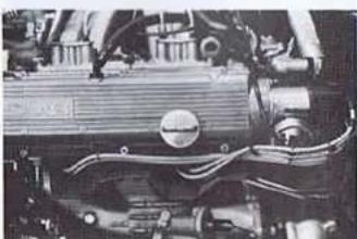
natural_image
Close-up of a mechanical engine component with visible hoses and springs (no text or symbols)NOTE! Do not confuse the engine and transmission drain plugs. Do not operate the engine with the oil fill cap removed or loosely installed. Oil spilled over the engine creates a fire hazard.
Oil Filter
The oil filter should be changed at the same time as the engine oil, in accordance with the maintenance schedule.
NOTE! Your new car came with a "break-in" filter. The service life of this filter is 1000 miles. It MUST be placed at the 1000 mile service.
Apply a little oil to the rubber gasket on the new filter, and tighten the filter by hand.
Air Cleaner
The air cleaner is located on the left-hand side in the front part of the engine compartment. The cleaner cartridge is replaceable and should be changed as specified in the maintenance schedule. If the car is driven over dusty roads, the cleaner should be changed more frequently. The cartridge is made of a special grade of paper which may not be washed or moistened, but it may be cleaned carefully with compressed air. The air cleaner housing and cover should be wiped off from time to time.

Fuel Filter
The electric fuel pump is a submersible type located in the fuel tank. The fuel filter is located on the left-hand side in the engine compartment and should be changed as specified in the maintenance schedule.
Ignition System
A breakerless ignition system is used
WARNING! High energy ignition system develops dangerous primary and secondary voltages.
If the spark plugs are removed, take care that no dirt enters the cylinders. Use only the recommended spark plug heat range and gap to specification. Resistive-type lugs should not be used as resistive wire leads are used for radio interference suppression.
The firing is 1-3-4-2(cylinder number 1 is closest to the firewall).
COOLING SYSTEM
The cooling system is pressurized with a crossflow radiator and expansion tank.
Until the engine has reached its operating temperature, the radiator inlet is closed by a thermostat and the coolant circulates through the engine and the fresh air heater until it reaches the temperature at which the thermostat opens.
The radiator fan is electrically operated and is regulated by a thermostatic switch. The fan is only operative when the temperature of the radiator coolant is higher than the cut-in temperature of the thermostatic switch.
The radiator fan may continue to run, or may cut in, for a short while after the engine has been switched off.
WARNING! Boiling coolant can cause serious burns. Let the engine cool before removing pressure cap.
The cooling system operates under pressure. Always open the cap on the expansion tank slowly and allow any steam to escape before you remove the cap.
The radiator must not be screened or blocked off!
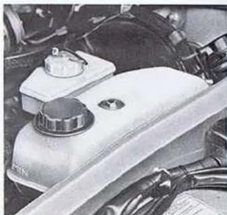
Checking the Coolant Level
The expansion tank is transparent to facilitate checking of the coolant level. The level should be between the MAX and MIN marks on the tank. When necessary, top up with the recommended anti-freeze coolant mixture (see below). After an empty expansion tank has been filled up, the engine should be run until warm and the tank topped up again.
natural_image
Close-up of a car engine bay with a mounted fuel tank and valve (no visible text or symbols)NOTE! Keep the coolant at the recommended level. Correct any leaks immediately. Operating the engine with low coolant level may cause damage to the cylinder head.
Changing Coolant
Draining
- Set the heater control to maximum heat.
- Loosen the pressure cap on the expansion tank.
- Open radiator drain cock which is located towards the bottom of the radiator on the right hand side.
- Open engine drain plug located to the right of the engine, under the exhaust manifold.
Filling
- Close the drain cock and ensure that the heater control is set to maximum heat.
- Fill the system with coolant until the expansion tank is filled.
- Open the bleeder nipple, allow the coolant to flow out of the nipple until free from air bubbles.
- Close the bleeder nipple, top up the expansion tank if necessary and replace cap.
Anti-Freeze Coolant Mixtures
The cooling system is factory filled with a mixture of ethylene glycol and water (50-50 mix). For maximum security against freezing and corrosion the glycol should be 50-70% of the mixture. Use antifreeze brands suitable for engines with aluminum alloy cylinder heads and mix with clean fresh water (see below).
To prevent freezing in the cold season and reduce the risk of boiling over in hot weather, never use pure water in the cooling system. Pure water is also undesirable as it affords no corrosion protection.
The factory fill coolant must be changed and the system flushed according to the maintenance schedule as the important corrosion inhibitors and other coolant additives lose their effectiveness with time and use. Without adequate corrosion protection, serious damage may occur to the cylinder head and other components in contact with the coolant. Corrosion protection may be depleted even though the coolant gives adequate anti-freeze protection and has an acceptable (alkaline) pH level of 7.5-11. When preparing a new coolant solution, mix the recommended ethylene glycol with water low in corrosive ions such as chlorides and sulfates. Avoid hard water which can cause clogging in the radiator. Do not use coolant booster additives. Keep the cooling system full and free of air pockets and foaming.
NOTE! When topping up the system, premix the ethylene glycol with a suitable quantity of water. As full circulation cannot take place until the thermostat opens, there is still a risk of the engine being damaged by ice if the glycol and water were added separately and did not mix quickly enough.

The 1982 Saab has three distinct systems for controlling emissions to the atmosphere. The sections that follow briefly describe these systems.
I. The Crankcase Emission Control System II. The Evaporative Emission Control System III. The Exhaust Emission Control System
Engine Families
1982 Saabs imported to the United States are divided into two engine families (normally aspirated and turbocharged) that meet the emission control standards indicated below. The engine family and appropriate tune-up specifications are identified on a label affixed to the left front inner fender.
Both families meet U.S.A. Federal Standards and California State Standards. CSA 2.0V6FNT3—Saab 900, 900S CSA 2.0V6FTTX—Saab 900 Turbo
Saab engines are equipped with the following systems to ensure compliance with the applicable standards as described above:
A. Continuous Injection System
B. Lambda Control System
C. Three-way Catalyst
D. Decel Dashpot (automatic transmission)
E. Decel Fuel shut off (manual transmission)
F. Exhaust Gas Recirculation
I. CRANKCASE EMISSION CONTROL SYSTEM
A completely closed crankcase ventilation system is used. Crankcase fumes are drawn directly into the inlet manifold under all operating conditions except full load and high blow-by
when some gases are diverted ahead of the throttle body. (On Turbo models all crankcase gases are diverted ahead of the throttle body). The oil separator in the valve cover also serves as a flame arrestor.

- Crankcase
- Exhaust Manifold
- Camshaft Cover
- Oil trap and flame arrestor
-
Nipple with orifice
-
Hose
- Inlet Manifold
- Air cleaner adapter
• except turbo
II. EVAPORATIVE EMISSION CONTROL SYSTEM
A sealed fuel system is used to prevent the emission into the atmosphere of vapors from the stored gasoline supply. Evaporated fuel is vented from the fuel system to the charcoal canister which is connected to the throttle housing. The evaporated fuel is purged from the charcoal canister and burned by the engine when it is running. The fuel tank is pressurized to about 1.5 psi by a valve in the ventilation line.

- Fuel Tank
- Fuel Tank Vent Lines
- Ventilation Line to Charcoal Canister
- Inlet Air
- Charcoal Canister
-
Fuel Distributor
-
Air Cleaner
- Inlet Air and Gas
Vapors - Inlet Vapors
- Check Valve
- Pressure Valve
- Rollover Valve
III. EXHAUST EMISSION CONTROL SYSTEMS
A. Continuous Injection System
The C.I. System allows precise fuel metering which results in low baseline emissions while retaining good driveability, performance and economy. The intake air flow volume determines the correct momentary quantity of fuel metered to the four intake port injectors for most efficient combustion. The engine draws in more or less air depending on its speed and the load applied.

- Fuel Tank
- Fuel Pump
- Fuel Accumulator
- Fuel Filter
- Fuel Distributor
- Warm Up Regulator
-
Air Flow Sensor Plate
-
Cold Start Valve
- Injection Valve
- Thermo-Time Switch
- Auxiliary Air Valve
- Throttle Plate
- Pressure Relief Valve
- Air Cleaner
B. Lambda Control System
Lambda Control System is a closed loop feedback system adapted to the C.I. System to constantly maintain close air/fuel ratio control under all operating conditions. At an air/fuel ratio of 14.5 to one (Lambda = 1 at this ratio), all three regulated pollutants (hydrocarbons, carbon monoxides, oxides of nitrogen) may be simultaneously controlled efficiently by a special threeway catalyst. An oxygen sensor in the exhaust manifold monitors the oxygen content of the exhaust and sends a proportional signal to an electronic control unit (under the rear seat). This signal is compared to a predetermined value and an output signal is sent to a fuel pressure modulating valve to make the necessary fine adjustment of the air/fuel ratio. Until the sensor warms up after the engine is started, the modulating valve will operate at a constant predetermined value. This is also true in the case of wide open throttle operation or engine speeds above 3800 RPM (Turbo Only) and in the event of sensor failure (the car will not be disabled).
A maintenance reminder lamp, labeled "EXH", on the instrument panel illuminates every 30,000 miles to indicate that the oxygen sensor is scheduled for replacement. (After this service is performed your dealer will reset the lamp actuating mechanism.)
C. Three-Way Catalyst
The catalytic converter contains a special platinum and rhodium coated dual segment substrate which simultaneously frees oxygen from oxides of nitrogen and oxidizes (burns) hydrocarbons and carbon monoxide. Unleaded fuel is required to protect the conversion efficiency of the catalyst.

- Electronic Control Unit
- Wide Open Throttle Switch (Turbo only)
- Oxygen Sensor
- Catalytic Converter
- Modulating Valve.
D. Decel Dashpot (Automatic Transmission Only)
The decel dashpot acts upon the throttle linkage to minimize incomplete combustion during engine deceleration.
E. Decel Fuel Shutoff (Manual Transmission Only)
A solenoid operated air by-pass valve reduces air flow in the air flow sensor; lowering the fuel distributor plunger interrupting fuel flow during deceleration. The solenoid is controlled by an engine speed relay and a throttle contact switch. During deceleration at engine speeds above 1450 RPM the solenoid opens the by-pass valve. When the speed drops below 1250 RPM the system de-activates allowing normal operation.
F. EGR System
Exhaust gas recirculation (EGR) is employed to reduce the formation of oxides of nitrogen by introducing a small amount of inert gas (exhaust) to the intake charge to lower the peak combustion temperature. Exhaust gases are routed from the cylinder head through a valve controlled by intake and manifold vacuum and are introduced into the intake manifold. A thermostatic valve delays system operation until the engine is warm.
The EGR system on Turbo models employs a single port control signal while the normally aspirated engines have a two port control pickup at the throttle housing.
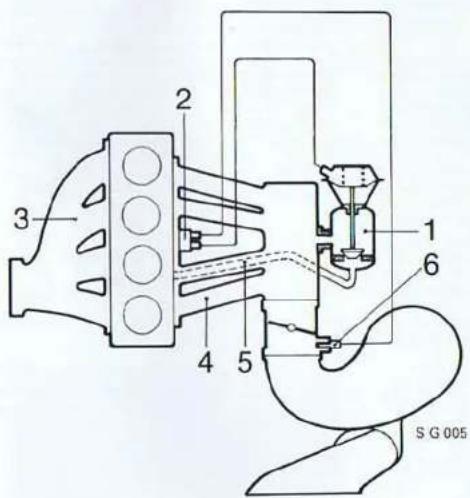
-
EGR Valve
-
Vacuum Signal Thermostatic Valve
-
Exhaust Manifold
-
Inlet Manifold
-
EGR Pipe
-
Two Port Outlet (Single port, 900 Turbo)
TURBOCHARGING SYSTEM (900 TURBO)
The turbocharger is an exhaust driven compressor that increases the flow and pressure of the air entering the cylinders. This allows induction and burning of a larger fuel charge thereby increasing power output over that of a conventional engine.
Being driven by the flow of exhaust gases, the speed of the turbocharger and, therefore, the charging pressure, are proportional to the speed and load of the engine. A charge pressure regulator (wastegate) controls the flow of exhaust gases to the turbine once a preset pressure limit has been reached. The regulator allows boost to develop quickly at relatively low engine speeds, but limiting the maximum pressure to a level which prevents the engine knock when fuel as low as 87 minimum octane is used.
Turbocharged engines are equipped with an engine oil cooler that is located at the lower left of the radiator. The impeller shaft bearing actually floats on a thin film of engine oil circulated through the turbocharger housing by the engine oil pump. Maintaining a clean oil supply is therefore important to the service life of the unit.

58149
- Turbocharger
- Exhaust Turbine
- Compressor Wheel
- Charge Pressure Regulator (wastegate)
- Wastegale actuator
- Overpressure safety switch
- Throttle plate
- Fuel injection system
- Exhaust manifold
- Exhaust pipe
TRANSMISSION
The transmission and differential are located beneath the engine and assembled to form an integral unit with the engine. Part of the transmission case serves as the engine oil sump. The forward part of the transmission comprises a primary gear case which delivers power from the rear of the engine crankshaft via chains.
For suitable grades of oil, refer to the Specifications Section.
Manual Transmission
The dipstick is located on the right-hand side of the engine. The oil level should be between the MAX and MIN marks on the dipstick. To add oil, pour the oil into the dipstick pipe. The clutch fluid is supplied from the brake fluid reservoir.

natural_image
Close-up of mechanical components with hoses and connectors (no visible text or symbols)Automatic Transmission
The dipstick has different markings for hot and cold oil levels.
Check the oil level as follows:
Set the hand brake and run the engine for at least 15 seconds at idling speed with the range selection lever in the D position. Then at least 15 seconds in the R position and 15 seconds in the P position, whereupon the check is performed with the selector lever still in the P position (Engine running). Graduations are provided for cold oil (104^, + 40^) and hot oil (194^, + 90^) . Note that at very low temperatures the oil level can therefore lie considerably under the level for cold oil which has been graded for oil at a temperature of 104^(+40^) . The difference between the minimum and maximum levels is 1 pint (0.5 litres).
natural_image
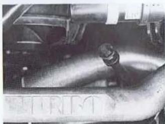
Close-up of a car's engine compartment with visible valve and pipe (no text or symbols)NOTE! Do not confuse the engine and transmission drain plugs. A special wrench is required for the transmission plug.

B. Electrical System
BATTERY
The battery is one of the most important components in the car and must, therefore, be carefully maintained. The electrolyte should be level with the lower edge of the filler pipes. Top up as necessary using distilled water only.
In the case of cars that are equipped with a maintenance-free battery, the electrolyte level does not need checking.
WARNING! The battery contains diluted sulphuric acid which is highly corrosive. Should the acid come into contact with your eyes, skin or clothing, rinse immediately with water. Call a doctor if the acid gets in your eyes. Batteries that are being charged or are fully charged give off flammable hydrogen gas.
The battery charge should be checked at regular intervals. This is especially important during the winter when the capacity drops due to low temperatures.
Never connect the battery cables to the wrong terminals.
BOOSTER CABLE CABLE CONNECTIONS
To start a vehicle with a discharged battery using a booster battery or another vehicle connect booster cables as follows:
Connect one booster cable from the positive (+) terminal of one battery to the positive (+) terminal of the other battery.
B. Connect one end of the second cable to the negative (−) terminal of the charged battery.
C. Connect the other end of the second cable to a solid, stationary metallic point on the engine of the car with the discharged battery (such as lifting ring or cylinder head).
D. Start engine of vehicle with discharged battery.
E. Remove booster cables by reversing the above procedure—Remove last negative (−) connection first.
Do not reverse the battery connections. If the cables are reversed, even momentarily, the alternator will be damaged. The insulated positive cable must be connected to the positive (+) post of the battery and the ground cable to the negative (−) post. The battery must not be disconnected from the car's electrical system while the engine is running.

natural_image
Technical diagram of a vehicle engine bay with mounting brackets and structural components (no text or labels)ALTERNATOR
The alternator is located at the top of the engine near the firewall. It is driven by a V-belt from a pulley on the crankshaft. It is important that the V-belt be properly tensioned. If the belt is too slack, it can be tightened by loosening the screws and pressing the alternator outwards.
The belt should be tightened such that the center of the belt can be moved about one half inch (10-15 mm.)
WINDSHIELD WIPERS
Inspect and clean the rubber blades of the wind-shield at regular intervals. Methyl Alcohol is recommended for cleaning. If the blades show signs of wear, they should be replaced. 400 mm. (16 in.) blades are specified.
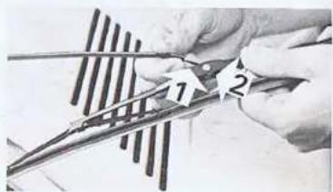
Changing the Windshield Wiper Blades
Lift the wiper arm. Depress the plastic clip (1) and pull off the complete wiper blade (2) (see illustration).
natural_image
Close-up of hands using scissors to cut metal strips (no text or symbols visible)Free the rubber from the retainer (see illustration) by pressing together the two shiny metal pieces and twisting the rubber. The rubber can now be withdrawn through the other retainers. To fit the rubber, slide it through the four retainers and then tighten it so that the retainer at one end engages the recess in the blade rubber.
Washers
The reservoir holds 6.5 U.S. quarts. Fill up with washer fluid and water. The spray nozzles consist of rotatable balls; to adjust the direction of the jet, insert a needle in the hole of the nozzle.

natural_image
Technical line drawing of a structural frame with an inset showing a cross-section detail (no text or symbols)
natural_image
Close-up of a white, cloud-shaped object resting on a dark surface, possibly a container or machine component (no visible text or symbols)HEADLIGHTS, BULB, FUSES
Headlights
The headlights are mounted in cradles and are provided with two adjustment screws which are accessible without removal of the headlight trim. The upper screw is used for vertical adjustment and the side screw for horizontal adjustment.
It is extremely important that the headlights be correctly adjusted to achieve the best possible lighting effect without any risk of blinding on-coming drivers.
All adjustments should be done by an authorized Saab dealer, according to specifications and/or applicable state laws.
Instrument Illumination, Control
Illumination and Indicator Warning Lights
All the bulbs in the instrument assembly are mounted in bayonet fittings and are accessible from the back of the panel. The bulb for head-light switch illumination is located within the switch.

Changing Other Light Bulbs
Loosen the retaining screws and remove the glass. Change the bulb and check that the new one is securely in place and makes good contact. Wipe off the lamp assembly and replace the glass making sure that it fits tightly.
Fuses
The fuses are located in a fuse box with a transparent cover (retained by two thumb screws), located on the left in the engine compartment. Spare fuse holders are provided between the rows of fuses.
When a fuse has blown, the strip of metal running along the length of the fuse will have been burned through. When changing fuses, make sure that the new fuse has the same rating as the old one (see table). Fuses of the same rating have a common color. The rating is also marked on the fuse. Insert the fuse with the metal strip up.
If the same fuse blows repeatedly, take the car to an authorized Saab dealer and have the wiring and other electrical equipment checked.
Rating.
| No. | Function | Amperes |
| 1 | High beam, RH | 8 |
| 2 | High beam, LH | 8 |
| 3 | Low beam, RH | 8 |
| 4 | Low beam, LH | 8 |
| 5 | Radiator fan | 25 |
| 6 | Electric rear window defroster | 16 |
| 7 | Interior lighting | 5 |
| 8 | Fuel pump | 16 |
| 9 | Hazard warning flasher | 8 |
| 10 | Brake lights | 8 |
| 11 | Fan, air conditioning | 8 |
| 12 | Parking and tail light, RH | 5 |
| 13 | Parking and tail light, LH | 5 |
| 14 | Horn (and power windows) | 16 |
| 15 | Elec. side view mirrors | 8 |
| 16 | Electric heating, seat | 16 |
| 17 | Fan, heating and ventilation | 25 |
| 18 | Air conditioning | 16 |
| 19 | Warning lights | 8 |
| 20 | Direction indicators | 8 |
| 21 | Windshield wipers | 8 |
| 22 | Cornering lights | 16 |
WIRING DIAGRAMS
Wiring diagrams are given in the Saab 900 Service Manual, Section 3.
Relays
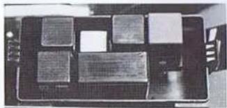
There are two relay panels located on the inner left front fender. Depending on equipment variations they may contain up to 16 relays.
The front panel houses the following relays:
| Position | Name | Part Number |
| A | Blank | |
| B-C | Accel. Enrichment Time relay | 8575151 |
| D | Accel. Enrichment Pulse Relay | 8574618 |
| E | Decel System Relay (Manuals) | 8574899 |
| F | Hot Start Pulse Relay | 8568271 |
| G | Cold/Hot Start Ground Relay | 8533176 |
| H | Engine Speed Relay (Turbo) | 8578346 |
natural_image
Top-down view of a black electronic device with multiple rectangular components (no visible text or symbols)The following relays may be found in the rear panel which also contains electrical system fuses:
| Position | Name | Part Number |
| A-B | Headlight Relay | 8562100 |
| C | Rear Window Def. Relay | 8522310 |
| D | Air conditioning Relay | 8572190 |
| E | Ignition Lock Relay | 8572943 |
| F-G | Fuel Pump/RPM Limiter Relay (Turbo) | 8579484 |
| G | Fuel Pump Relay (except turbo) | 8539728 |
| H | Blank | |
| J | Cooling Fan (AC) Relay | 8522310 |
| K | Horn Relay | 8522310 |

natural_image
Close-up of a mechanical device with multiple vertical slots and a central button (no visible text or symbols)C. Steering and Brakes
BRAKES
The footbrake system is power-assisted, with the result that the force applied to the brake pedal is amplified on braking. However, this additional power is only available when the engine is running. Much greater pressure on the brake pedal will be needed to brake the car when the engine is switched off, for example, when the car is being towed.
There are two warning lights on the instrument panel, one for the handbrake and one for the footbrake. The handbrake warning light will glow when the brake is set. The footbrake warning light will glow when the fluid level in the brake fluid reservoir has dropped below the MIN mark. This may be an indication that there is a leakage in the system. Since the brakes operate on a dual-circuit system, each circuit operating on diagonally opposed wheels, only one circuit will be affected at a given time, and the car can be driven carefully with a reduced braking effect to an authorized Saat dealer.
NOTE! If the brake pedal continues to move down under constant pressure or the car pulls to one side during braking or an abnormally loud or metallic noise is heard during braking see an authorized Saab dealer immediately to have the braking system inspected.
Both the footbrake and the handbrake are self-adjusting. It is therefore impossible to tell by the length of the pedal stroke whether the brake linings are worn out and need to be replaced.
Consequently it is very important to check the thickness of the brake linings regularly as specified in the maintenance schedule.
NOTE! Brake pads should always be changed by an authorized Saab workshop. A special tool is required to turn back the parking brake automatic adjuster before new front brake pads can be installed. Fit only original Saab brake pads. Semi-metallic pads may be installed in the outboard front positions only.
Checking the Brake Fluid
The brake fluid reservoir (container) is transparent to facilitate checking of the fluid level. The level should be between the MAX and MIN marks. Use only recommended brake fluid,

natural_image
Close-up of a white electronic device with a central component and wires, no visible text or symbols.Over a period of time in use, the brake fluid will deteriorate, since it gradually absorbs water and oxidizes. It is therefore important that the fluid be changed as specified in the maintenance schedule. This work should be carried out by an authorized Saab dealer.
STEERING
All Saab 900's have rack and pinion type steering with power assist.
Check the fluid level in the servo reservoir regularly, with the engine off. The dipstick in the reservoir cap is graduated separately for cold and warm fluid. If the car has reached its normal running temperature, the fluid level should be between the marks for warm (A) and cold (B). If the fluid level is checked when the car is cold, the level should be between the cold fluid (B) mark and the tip of the dipstick (C). Top up with fluid labeled "GM Power steering fluid". DO NOT USE AUTOMATIC TRANSMISSION FLUID.


D. Wheels and Tires.
A car's tires and wheels are components vital to motoring safety. The tubeless radial tires and wheels supplied with the Saab 900 have been specially selected for the different models and are major factors contributing to its exceptional roadholding and stability. Consult your Saab dealer before fitting nonstandard wheels or tires. See tire and wheel applications chart, Specifications Section.
Tire Pressures
Check tire pressures regularly.
Adjust tire pressures to suit the load and speed normal for the car. See tire pressure table, Specifications Section. The recommended pressures are for tires when cold. Never reduce the pressure when the tire is warm. If tire pressures are checked when the tires are warm then the pressure should only be increased. Incorrect tires. See tire and wheel applications chart, Specifications Section.
NOTE! Do not forget to adjust the tire pressures if the load or speed is radically altered. Add 1.5 psi to light load value if the car has air conditioning.
Wear Indicators
The tires are fitted with wear indicators—a transverse strip (approx. 12mm, 0.5 in., wide) without a pattern appears when 1.6 mm (0.06 in.) of the tread remains. When this strip is visible the tire should be replaced.
Winter tires
The 185/65 SR15 standard steel-belted radial ply tires, if they have at least half their original tread depth, are also suitable for winter use in moderate climates where snow and ice are not too severe. The 900 Turbo 3-door model is equipped with wide profile tires which have been developed to give the greatest possible roadholding and stability under both wet and dry driving conditions with the result that the tread compounds and designs are not suitable for use on ice and snow. We therefore recommend winter tires or "all weather" tires for this model when driving on snow or ice. (See Winter Driving, Starting and Driving Section.)
Tire Rotation
The front-wheel drive causes the front tires to wear more than the rear tires. If it is desired to have the tires wear evenly, they should be exchanged front to rear after a certain period of driving so that the least worn tires are at the front. By switching the tires in this manner, the service life of all four tires will remain approximately equal. Make sure that the tires are always rotated in the same direction—the left front wheel should thus change place with the left rear wheel. Do not change radial tires side to side.
WHEEL CHANGING
The tool kit, jack and a compact type spare wheel are stored under a cover in the floor of the rear part of the luggage compartment.

natural_image
Close-up of a mechanical component with concentric rings and central slots (no visible text or symbols)To jack up the car, install the jack in one of the jacking points (front or rear) located underneath the sill beams (see illustration).
If a garage jack is used, the lifting heads must be located under the reinforced parts of the underbody.
WARNING! Never crawl under the car when it is jacked up.
-
Apply the handbrake. Slide the jack into the attachment points and crank it down until it touches the ground.
-
To remove the hub cap, insert a screw-driver behind the cap and lever it off
- Back off the wheel nuts half a turn. Check that the jack has located properly against the flange on the sill beam and that the whole of the base is firmly in contact with the ground.
- Jack up the car until the wheel is clear of the ground, then remove the wheel nuts and the wheel.
- Mount the wheel and tighten the wheel nuts loosely. Check that the wheel and nuts are correctly positioned.
- Lower the car. Tighten the wheel nuts in the order shown in the illustration below. Tighten to 65-80 ft, lbs. Never use an impact wrench for final tightening of wheel nuts. Carefully observe the torque limit to avoid wheel damage.
NOTE! The original equipment road wheels are designed to be mounted using nuts with a conical seating surface. These nuts are suitable for mounting the compact spare. Certain accessory wheels available from Saab dealers require special shouldered nuts which do not fit the spare wheel. Purchase four conical nuts for the spare if the car is to be so equipped.
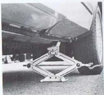
natural_image
Close-up of a car suspension system mounted on a vehicle chassis (no visible text or symbols)
natural_image
Close-up of a car wheel rim with numbered slots (1–4) and mounting holes, no visible text or symbols.
E. Specifications
GENERAL
| Overall length incl bumpers | (4764mm) | 187.6" |
| Overall width | (1690mm) | 66.5" |
| Overall height (empty) | (1420mm) | 55.9" |
| Road clearance (at curb weight) | (150mm) | 6" |
| Track, front wheels | (1430mm) | 56.3" |
| Track, rear wheels | (1440mm) | 56.7" |
| Wheelbase | (2517mm) | 99.1" |
| Turning radius | (5.6m) | 220.5" |
WEIGHT
| Curb weight | 2584-2859 lb. |
| Gross vehicle weight rating | 3600-3810 lb. |
| Weight distribution,at curb weight | 59-62% front |
| at gross vehicle weight rating | 49-51% front |
| Trunk volume (SAE) Hatchback | 14.9 cu. ft. |
| Hatchback, parcel shelf removed | 19.1 cu. ft. |
| Sedan | 14.2 cu. ft. |
| Vehicle capacity weight, fivepersons and 180 lb. luggage | (422 kg) 930 lb |
| Max roof rack load | (100 kg) 220 lb |
| Max trailer weightwith trailer brakes | (900 kg) 2,000 lb |
| without trailer brakes | (450 kg) 1,000 lb |
| Max trailer tongue weight | (90 kg) 198 lb |
*Weight variation depends on model, configuration and options.
ENGINE
| Type | 4 cyl. 4 stroke inline OHC with continuous fuel injection |
| Cylinder Bore | 3.543" |
| Stroke | 3.071" |
| Displacement | 121 cu. in. |
| Order of Firing (Cylinder 1 nearest firewall) | 1-3-4-2 |
Valve Clearance, Cold Engine:
| Intake, all | (0.15-0.30mm) | 0.006"-0.012" |
| Exhaust, Standard | (0.35-0.55mm) | 0.014"-0.020" |
| Exhaust, Turbo | (0.40-0.50mm) | 0.016"-0.020" |
| Ignition Advance Setting 20° BTDC @ 2000 RPM (vac. hose plugged) | ||
| Spark Plug gap | 0.024-0.028" | |
| Engine Idling Speed in Neutral (A.C. off) | 875 ± 50 RPM | |
| Normally | ||
| Aspiration | Turbocharged | Aspirated |
| Engine Family Number | CSA2.0V6FTTX | CSA2.0V6FNT3 |
| Power Rating, SAE Net HP @ RPM | 135 @ 4800 | 110 @ 5250 |
| Max. Torque at 3500 RPM | 160 ft. lbs. | 119 ft. lbs. |
| Compression Ratio | 7.2:1 | 9.25:1 |
| Dashpot Adjustment* (Automatic) | 2200 ± 100 RPM | 2500 ± 100 RPM |
| Decel Fuel Shutoff (Manual) | Activates above 1450 RPM, Throttle Closed; deactivates below 1250 RPM | |
| Oil Capacity Including Filter | 4.5 U.S. gts. | 4 U.S. gts. |
| Recommended Fuel(16.6 U.S. gal capacity) | Unleaded 87(91 RON min.) | Unleaded 87(91 RON min.) |
| Wastegate Setting** | 0.5 ± 0.05 bar | N/A |
*Adjust plunger to contact throttle lever with engine operating at above specification.
(Disconnect EGR on Turbocharged engines.)
**3000 RPM, engine under full load.
OIL VISCOSITY
| Hot weather | SAE 10W40, API Service SE or SF |
| Normal .. (Alternate: SAE 10W30) | SAE 10W40, API Service SE or SF |
| Cold Weather below 0°F | SAE 5W20, API Service SE or SF |
FUEL SYSTEM
| Type | Bosch K-Jetronic (CIS) |
| Fuel Pump | Electric, in fuel tank |
| Fuel Tank: Capacity | 16.6 U.S. gallons |
| Material | HDPE (High density polyethylene) |
COOLING SYSTEM
NOTE! The Radiator air flow must not be blocked off.
Coolant volume incl. heating system .... (10 liters) 10.5 U.S. qts., 8.8 Imperial qts.
Thermostat opens at (88°C) 190°F
Anti-freeze ..... Ethylene glycol, with aluminum corrosion protection properties, 50-70% mixed with water
| DRIVE BELTS | Saab | Gates | Dayco |
| Waterpump-Alternator | 83 84 927 | 8210 | 15390 |
| Power Steering | 93 39 409 | 8216 | 15495 |
| Air Conditioning | 93 44 623 | 8256 | 17470 |
MANUAL TRANSMISSION
Type 5 speed, all synchromesh with final drive and differential
Oil capacity (2.5 liters) 3 U.S. qts.
Oil Specifications SAE 10W30 (Service SE acc. to API)
Hydraulic clutch .... Single dry plate with spring-loaded hub
| Gear ratios total (includes primary and final ratios): | |
| 5-Speed | |
| 1st gear | 13.97 |
| 2nd gear | 7.89 |
| 3rd gear | 5.30 |
| 4th gear | 3.82 |
| 5th gear | 3.08 |
| Reverse | 15.34 |
Recommended Shift Points For Economical Driving
| 5 Speed900, 900S | 5 SpeedTurbo | High AltitudeDriving(All) | |
| Gear Change | Speed | Speed | Speed |
| 1st to 2nd | 12 mph | 15 mph | 18 mph |
| 2nd to 3rd | 22 mph | 25 mph | 28 mph |
| 3rd to 4th | 30 mph | 40 mph | 43 mph |
| 4th to 5th | 40 mph | 45 mph | 48 mph |
AUTOMATIC TRANSMISSION
Type 3-speed with torque converter, final drive and differential
Selector positions P.R.N.D.2-1
Oil volume, automatic transmission ..... 8.5 U.S. qts, 7.2 Imperial qts.
Grade of oil for automatic transmission fluid ..... Type "F" (M2C33F)
Oil Volume, final drive (1.25 liters) 1.3 U.S. qts., 1.1 Imperial Qts.
Grade of oil for final drive .... EP oil SAE 80 in accordance with API-GL-5, or GL-4
Primary gear ratio: Normally aspirated 0.97:1 Turbocharged 0.878:1
Gear ratios (transmission): 2.39:1
1st gear 2.00-1 1.45-1
2nd gear 1:1
3rd gear Reverse gear 2.09:1
Final Drive ratio 3.89:1
BRAKE SYSTEM
Make Girling & A.T.E.
Footbrake Hydraulic disc brakes with power
assist, two circuit system serving
diagonally opposed pairs of wheels.
Brake and clutch fluid DOT 4 Brake fluid
Disc diameter: (860mm) 11.02"
Front (260mm) 11.62 (269.5mm) 10.63"
Rear
Swept areas: (1423cm) 222 in
Front wheels .... (1402m) .... 125 m
Rear wheels (1095cm) 170 m.
Total (2527cm) 392 m.
Handbrake .Mechanical, acting on front discs
Brake pads Use original equipment type
semi-metallics pads are only to be
fitted at the outer front positions.
SUSPENSION
Suspension elements, front and rear .... Coil springs
Total spring compression/elongation:
Front (180mm) 7.1"
Rear (170mm) 6.7"
Shock absorbers:
Type Hydraulic, telescopic
(900S, Turbo—Gas pressure)
Maximum working stroke, fitted to car:
Front (96mm) 3.8"
Rear (158mm) 6.2"
Steering:
Steering gear Rack and pinion
Wheel turns, lock to lock:
Power steering 3.65
Oil specification, Power Steering .... GM Power steering fluid
WHEELS AND TIRES
Wheel sizes:
Saab 900: 5½ J × 15 CH (steel)
Saab 900S and Turbo: 5½ J × 15 H2 (aluminum alloy)
Spare wheel (All): 4 J H1 × 15"
Tire dimensions:
ALL 900 (except Turbo 3-Dr.) 185/65 SR 15
900 Turbo 3-Dt. 195/60 HR 15
Compact Spare T115/70 D15
TIRE PRESSURE (cold tires)
| Tire Size | Recommended Pressure | |
| Light Load Ft./Rear | Max. Load Ft./Rear | |
| 185/65 SR 15 | 27/29 | 30/32 |
| 195/60 HR 15 | 27/29 | 30/32 |
| Compact Spare (All) | 60 PSI | |
Check tire pressure with cold tires.
Front Wheel Alignment:
Toe-in (measured at rims) (2 ± 1mm) 0.08 ± 0.04 in.
Camber 12^±12^
Caster 2° ± ½°
ELECTRICAL SYSTEM
Voltage 12V
Battery capacity 60AH
Starter capacity 1.1 HP
Alternator, max. charging current/voltage 72 Amps/14V
Spark Plugs:
Type NGK-BP6ES; Champion N8Y;
Bosch W175 130,
Thread M14
Thread Length (8mm) 0.7"
Electrode gap (0.6mm-0.7mm) 0.024"-0.028"
Fuses and relays . See Technical Information
Section, Electrical System.
| Light Bulbs: | Power | SAE Trade No. | Quantity | Other lighting: | |||
| Instruments | 3W | 161 | 2 | ||||
| Ignition switch | 2W | 53 | 1 | ||||
| Headlights high/low beam | 65/55W | 6052 | 2 | Heating and ventilation control | 1.2W | ** | 1 |
| Optional halogen headlights | 65/55W | H-6052 | 2 | Cigarette lighter | 1.2W | ** | 1 |
| Front direction indicators/sidemarker | 21/5W | 1157 | 2 | Ashtray | 1.2W | ** | 1 |
| Rear direction indicators | 21/5W | 1157 | 2 | Cartridge bulb | |||
| Cornering lamps/parking lights | 21/5W | 1157 | 2 | ||||
| Rear lights | 5W | 67 | 2 | ||||
| Brake lights | 21W | 1156 | 4 | ||||
| Back-up lights | 21W | 1156 | 2 | ||||
| Side back-up lights | 21W | 1156 | 2 | ||||
| License plate light | 5W | * | 2 | ||||
| Interior lighting: | |||||||
| Dome | 10W | * | 1 | ||||
| Rear-view mirror | 5W | 1 | |||||
| Glove compartment | 5W | 1 | |||||
| Luggage compartment | 10W | * | 1 | ||||
| Switch lighting: | |||||||
| Light switch | 1.2W | ** | 1 | ||||
| Hazard warning flashers | 1.2W | ** | 1 | ||||
| Electrically heated rear window | 1.2W | ** | 1 | ||||
| Control lights: | TOOL KIT | ||||||
| Charging | 2W | ** | 1 | Jack with crank handle | |||
| Oil pressure | 1.2W | ** | 1 | ||||
| Brakes | 1.2W | ** | 1 | Tool kit comprising: | |||
| Direction indicators | 1.2W | ** | 2 | Combination pliers | |||
| Electrically heated rear window | 1.2W | ** | 1 | Phillips screwdriver | |||
| High beam | 1.2W | ** | 1 | Screwdriver | |||
| Handbrake | 1.2W | ** | 1 | Socket wrench for wheel nuts | |||
| Seat belts | 1.2W | ** | 1 | Socket wrench for spark plugs | |||
| Fuel tank | 1.2W | ** | 1 | Socket screw key for removing and installing front passenger seat. | |||

F. Identification Numbers

G. Consumer Information
The following information is provided in accordance with the requirements of the Code of Federal Regulations, Part 575—Consumer Information as it pertains to aaab automobiles. Procedures established by the National Highway Traffic Safety Administration are used in conducting the tests and the information may be used for comparison with other makes.
Vehicle Stopping Distance
This figure indicates braking performance that can be met or exceeded by the vehicles to which it applied under different conditions of loading and with partial failures of the braking system. The information presented represents results obtainable by skilled drivers under controlled road and vehicle conditions, and the information may not be correct under other conditions.
This table applies to all 1982 Saab 900 models.
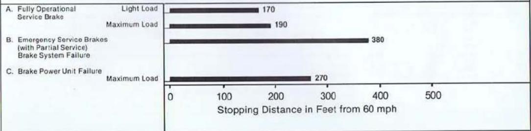
bar
| Category | Limiting Duration (Feet) | |---|---| | Light Load | 170 | | Maximum Load | 190 | | Emergency Service Brakes (with Partial Service) Brake System Failure | 380 | | Brake Power Unit Failure Maximum Load | 270 | The chart displays a single bar representing the stopping distance in feet from 60 mph. The labels above the bars indicate the scenario names. There is no additional data series or trends beyond the specific values.Tire Reserve Load
Refer to the Tire Information Label on the left side vehicle doorpost to determine the tire size that your vehicle is equipped with.
| This table lists the tire size designations recommended by Saab for use on the vehicles to which it applies, with therecommended inflation pressure for maximum loading and the tire reserve load for each of the tires listed. The tire reserveload indicated is met by each vehicle to which this table applies. | ||||
| This table applies to all 1982 Saab 900 models | ||||
| WARNING: Failure to maintain therecommended tire inflation pressure or to increasetire pressure as recommended when operating at maximum loaded vehicle weight, orloading the vehicle beyond the capacitiesspecified on the tire information placard affixed to the vehicle, may result in unsafeoperating conditions due to premature tirefailure, unfavorable handling characteristics, and excessive tire wear. The tire reserveload percentage is a measure of tire capacity, not of vehicle capacity. Loading beyondthe specified vehicle capacity may result infailure of other vehicle components. | RECOMMENDEDTIRE SIZEDESIGNATIONS | RECOMMENDED COLD INFLATION PRESSUREFOR MAXIMUM LOADED VEHICLE WEIGHT | TIRERESERVELOADPERCENTAGE* | |
| FRONT | REAR | |||
| 195/60 HR 15 | 30 | 32 | 18.4% (3-Dr.) | |
| 185/65 SR 15 | 30 | 32 | 19.3% (3-Dr.) | |
| 17.1% (4-Dr.) | ||||
| * The difference, expressed as a percentage of tire load rating, between (a) theload rating of a tire at the vehicle manufacturer's recommended inflation pres-sure at maximum loaded vehicle weight and (b) the load imposed upon the tire bythe vehicle at that condition. | ||||
Tire Quality Grading
Radial tires manufactured after Oct. 1, 1980 must be graded and labeled in accordance with new Federal regulations. Standard tests are conducted to measure performance in the areas of treadwear, traction and temperature resistance. Refer to the tire sidewall for the specific quality grades of the tires provided on your new Saab. Compact spare tires are exempt.
DOT QUALITY GRADES
TREADWEAR
TRACTION ABC
TEMPERATURE ABC
ALL PASSENGER CAR TIRES MUST CONFORM TO FEDERAL
SAFETY REQUIREMENTS IN ADDITION TO THESE GRADES.
TREADWEAR
The treadwear grade is a comparative rating based on the wear rate of the tire when tested under controlled conditions on a specified government test course. For example, a tire graded 150 would wear one and one half (1½) times as well on the government course as a tire graded 100. The relative performance of tires depends upon the actual conditions of their use, however, and may depart significantly from the norm due to variations in driving habits, service practices, and differences in road characteristics and climate.
TRACTION
The traction grades, from highest to lowest, are A, B, C, and they represent the tire's ability to stop on wet pavement as measured under controlled conditions on specified government test surfaces of asphalt and concrete. A tire marked C may have poor traction performance. Warning: The traction grade assigned to this tire is based on braking (straightahead) traction tests and does not include cornering (turning) traction.
TEMPERATURE
The temperature grades are A (the highest), B, and C, representing the tire's resistance to the generation of heat and its ability to dissipate heat when tested under controlled conditions on a specified indoor laboratory test wheel. Sustained high temperature can cause the material of the tire to degenerate and reduce tire life, and excessive temperature can lead to sudden tire failure. The grade C corresponds to a level of performance which all passenger car tires must meet under the Federal Motor Vehicle Safety Standard No. 109. Grades B and A represent higher levels of performance on the laboratory test wheel than the minimum required by law. Warning: The temperature grade for this tire is established for a tire that is properly inflated and not overloaded. Excessive speed, underinflation, or excessive loading, either separately or in combination, can cause heat buildup and possible tire failure.
III. SERVICE AND MAINTENANCE
The 1982 Saab 900 is covered by the following warranties:
- Limited 12 months/Unlimited Mileage Vehicle Warranty.
• 3 Year Corrosion Perforation Warranty - Federal (or California, as applicable) Vehicle Emission Control Warranty.
• Federal Emission Performance Warranty.
Detailed warranty information can be found in the Saab 900 Warranties/Service Record Booklet which accompanies this Owner's Manual. The booklet, if lost or misplaced, may be ordered through a Saab dealer or may be obtained by calling the nearest regional office of Saab-Scania of America, Inc. The September, 1981 edition of the booklet has Saab order No. 0291278.
A. Scheduled Maintenance
MAINTENANCE SCHEDULE
The Maintenance Schedule prescribes a program of instructions to the purchaser/operator of a 1982 Saab for maintenance which is reasonable and necessary to ensure the proper function, durability, and safety of the Saab automobile in normal use. The Schedule is divided into two parts: Emission System Maintenance and Vehicle Maintenance. The Emission System Maintenance instructions specify operations to ensure proper and safe function of Saab emission control systems throughout the useful life of the automobile. Additional maintenance is specified for certain components when operated under certain severe conditions. Maintenance, replacement, or repair of the emission control devices and systems may be performed by any automotive repair establishment or individual using any automotive part which has been certified according to U.S. EPA regulations governing voluntary aftermarket part self-certification. The Vehicle Maintenance Instructions are specified to ensure proper and safe functioning of the Saab automobile and its subsystems.
Note to California Residents Only: The Emission System Maintenance schedule is divided into two parts: Required Maintenance and Recommended Maintenance. This is done in compliance with provisions set forth by the California Emission Control System Warranty Regulations and applies to California purchasers/operators only. However, it is suggested that according to the applicable California regulations, "required maintenance" is that which must be performed to be eligible for coverage under the California Emission Control System Warranty. In not performing "recommended maintenance" California Emission Control System Warranty rights are in no way invalidated. Refer to the written warranty for further information pertaining to specific purchaser/operator rights and obligations.
NOTE! The Maintenance Schedule includes a break-in service at 1,000 miles. This important service will be done by your Saab dealer at no charge except for fluids and oil filter (which are to be paid for by the Saab owner). The car is equipped with a special break-in oil filter which must be changed at the break in service.
SERVICE RECORD RETENTION
Service coupons and record stubs are provided in the Saab 900 Warranties/Service Record booklet*. When scheduled services are performed your dealer will tear out the applicable coupon, check off the operations performed and enter it into the service file at the dealership. The servicing dealer's stamp, along with date and mileage at which the service was performed should be entered on the coupon stub which remains in your booklet. This is your permanent record that recommended maintenance has been performed. Authorized Saab dealers regularly receive up-to-date Service Manuals and bulletins from Saab-Scania of America, Inc., and are able, through their franchise agreement with Saab-Scania of America, Inc., to attend Saab service schools and purchase special tools and original equipment spare parts.
*Supplied when you purchased your new Saab.
IMPORTANT! It is advisable to retain receipts and, if possible, copies of shop work orders for all service and repair work, wherever performed.
| Required | Recommended | Where "miles" or "months" are shown, perform at whichever limit is reached first. | ||||
| A. EMISSION SYSTEM MAINTENANCE | 1,000Mi.Break In Service | Every 7,500 Mi.(5,000-Turbo)or 6 Mos. | Every 15,000Mi. or 12Mos. | Other | ||
| • | Valve Clearance—Check, if necessary adjust to specification (cold engine). Wash and blow clean oil separator in camshaft cover. | X | X—Every 15,000 miles. | |||
| • | Engine Head Bolts and Manifolds—Torque to specifications (including Turbocharger attachment bolts—Turbo). | X | ||||
| • | Spark Plugs—Replace and adjust gap to specification. | X—Every 30,000 miles. (1a. | ||||
| • | Air Cleaner Insert—Replace. | X—Every 30,000 miles. (1b. | ||||
| • | Fuel Filter—Replace. | X—Every 30,000 miles. (1c. | ||||
| • | Evaporative Emission Controlled Fuel System—Check fuel filler cap, vent lines, canister, and connections for wear, deterioration and/or damage which could cause leakage. Tighten any loose connections and/or replace any leaking components. | X—At 60,000 miles or 48 mos. and every 12 mos. thereafter | ||||
- Under the following severe driving conditions, replace every 15,000 miles:
a. Spark Plugs—Extensive idling, stop-and-go driving, towing, high speed driving, driving in cold climates over repeated short trips without sufficient
engine warm-up
b. Air Cleaner—Dusty conditions.
c. Fuel Filter—Dusty conditions or if clogged (accompanied by an increase in fuel pump operating noise level). - These columns refer to provisions of the California Emission Control System Warranty and apply only to residents of California.

| Required | Recommended | Where "miles" or "months" are shown, perform at whichever limit is reached first. | ||||
| A. EMISSION SYSTEM MAINTENANCE (continued) | 1,000Mi.Break in Service | Every 7,500 Mi.(5,000Turbo)or 6 Mos. | Every 15,000Mi. or 12Mos. | Other | ||
| - | Charcoal Canister—Replace. . . . . . . . . . . . . . . . . . . . . . . . . . . . . . . . . . . . . . . . . . . . . . . . . . . . . . . . . . . . . . . . . . . . . . . . . . . . . . . . . . . . . . . . . . . . . . . . . . . . . | . | X—Every 60,000 miles. | |||
| * | Crankcase Ventilation—Check connections and hoses. Tighten or replace as necessary. . . . . . . . . . . . . . . . . . . . . . . . . . . . . . . . . . . . . . . . . . . . . . . . . . . . . . . . . . . . . . . . . . . . . . . . . . . . . . . . . . . . . . . . . . . . . . . . . . . | .. | X—At 60,000 miles or 48 mos. and every 12 mos. thereafter. | |||
| * | Secondary Ignition Wires—Clean and inspect for cuts, burns, or abrasions. Replace any damaged wires. . . . . . . . . . . . . . . . . . . . . . . . . . . . . . . . . . . . . . . . . . . . . . . . . . . . . . . . . . . . . . . . . . . . . . . . . . . . . . . . . . . . . . . . . . . . . . . . . . . .. | . | X—At 30,000 miles. or 24 mos. and every 12 mos. thereafter. | |||
| * | Check resistance of ignition wires and replace, if necessary. . . . . . . . . . . . . . . . . . . . . . . . . . . . . . . . . . . . . . . . . . . . . . . . . . . . . . . . . . . . . . . . . . . . . . . . . . . . . . . . . . . . . . . . . . . . . . . . . . | . | . | X—At 60,000 miles. | ||
| * | Distributor Cap and Rotor—Replace. Check and adjust ignition timing to spec. . . . . . . . . . . . . . . . . . . . . . . . . . . . . . . . . . . . . . . . . . . . . . . . . . . . . . . . . . . . . . . . . . . . . . . . . . . . . . . . . . . . . . . . . . . . . . . . . . . | X—Every 60,000 miles. | ||||
| * | Ignition System—Check spark control system. . . . . . . . . . . . . . . . . . . . . . . . . . . . . . . . . . . . . . . . . . . . . . . . . . . . . . . . . . . . . . . . . . . . . . . . . . . . . . . . . . . . . . . . . . . . . . . . . . . X—Every 60,000 miles | X—Every 60,000 miles | ||||
| * | Oxygen Sensor—Replace sensor [all] and check operation of enrichment microswitch [Turbo only]. (Reset service reminder lamp.) . . . . . . . . . . . . . . . . . . . . . . . . . . . . . . . . . . . . . . X—Every 30,000 miles | X—Every 30,000 miles | ||||
| * | Oil and Oil Filter Change—(NOTE: Standard engine-7500 mi/6 mos.; Turbo—5,000 mi/6 mos.) ... | X | X | (2 | ||
- Under severe operating conditions (dusty conditions, frequent trailer towing or mountain driving, extensive idling, stop-and-go driving, driving in cold climates over repeated short trips without sufficient engine warm-up), change every 5,000 miles or 4 months (Turbos-3750 miles or 4 months), whichever
comes first. 3. These columns refer to provisions of the California Emission Control System Warranty and apply only to residents of California.
| Required | Recommended | Where "miles" or "months" are shown, perform at whichever limit is reached first. | ||||
| A. EMISSION SYSTEM MAINTENANCE (continued) | 1,000Mi.Break In Service | Every 7,500 Mi.(5,000-Turbo)or 6 Mos. | Every 15,000Mi. or 12Mos. | Other | ||
| * | Idle Speed—Check idle speed and adjust to specification, if necessary. | X | X—At 60,000 miles (and whenever the vehicle is relocated for a prolonged period of operation at a different altitude). | |||
| * | Deceleration System—Check operation; adjust to specification, if necessary. | X | X—At 60,000 miles. | |||
| * | EGR System—Clean and inspect EGR valve and inlet pipe. Check the EGR system operation. | X—Every 60,000 miles. | ||||
| * | Charging Pressure—Check; adjust to specification, if necessary. Reseal with anti-tampering wire. [Turbo only] | X | X—Every 15,000 miles. | |||
| * | Overpressure Safety Switch—Check operation.[Turbo only] | X—Every 15,000 miles. | ||||
- These columns refer to provisions of the California Emission Control System Warranty and apply only to residents of California.
| VEHICLE MAINTENANCE PROGRAM | Where "miles" or "months" are shown, perform at whichever limit is reache. first. | |||
| B. VEHICLE MAINTENANCE | 1,000Mi.Break InService | Every7,500 Mi.(5,000-Turbo)or 6 Mos. | Every15,000Mi. or12Mos. | Other |
| ENGINE | ||||
| V-Belts—Check; if necessary adjust tension or replace. | X | X—At 30,000 miles or 24 mos. and every 12 mos. thereafter. | ||
| Cooling System—Check hoses and connections for leaks. Tighten clamps or replace clamps or hoses if necessary. Check coolant level and anti-freeze content. | X | X | ||
| Engine Coolant—Flush system and replace with approved mix. | X—At 30,000 miles or 24 mos. and every 15,000 miles or 12 months thereafter. | |||
| Fuel Injection System Safety Check—Inspect components, electrical cables, fuel hoses, and all connections for wear, damage, and/or deterioration. Tighten any loose connections and/or replace any damaged components. | X | |||
| Exhaust System—Check for leakage and ensure that all fasteners and hangers are secure. Correct as necessary. | X | X | ||
| Where "miles" or "months" are shown, perform at whichever limit is reached first. | ||||
| B. VEHICLE MAINTENANCE (continued) | 1,000Mi.Break In Service | Every 7,500 Mi.(5,000-Turbo)or 6 Mos. | Every 15,000Mi. or 12Mos. | Other |
| MANUAL TRANSMISSION | ||||
| Gearbox Oil Level—Check; add as necessary . . . . . | X | |||
| Gearbox Oil—Change, clean magnetic drain plug.(Be careful not to confuse drain plugs for engine and gearbox) . . . . . . . . . . . . . . . . . . . . . . . . . . . . . . . . . . . . . . . . . . . . . . . . . . . . . . . . . . . . . . . . . . . . . . . . . . . . . . . . . . . . . . . . . . . . . . . . . . . . | X | |||
| AUTOMATIC TRANSMISSION | ||||
| Gearbox Oil Level—Check; add as necessary. . . . . . | X | |||
| Adjust automatic transmission gear selector control cable and retighten cover bolts under gearbox . . . . | X | |||
| Differential Oil Level—Check; add as necessary. . . . | X | |||
| Differential Oil—Change . . . . . . . . . . . . . . . . . . . . . . . . . . . . . . . . . . . . . . . . . . . . . . . . . . . . . . . . . . . . . . . . . . . . . . . . . . . . . . . . . . . . . . . . . . . . . . . . . . . | ||||
| B. VEHICLE MAINTENANCE (continued) | 1,000 MI. Break In Service | Every 7,500 MI. (5,000-Turbo) or 6 Mos. | Every 15,000 MI. or 12 Mos. | Other |
| ELECTRICAL SYSTEM | ||||
| Battery—Check electrolyte level (batteries with fill caps). Tighten cable terminals and coat with petroleum jelly. | X | X | ||
| Functional Check—Headlights, stoplights, directional lights, warning flashers, back-up lights, indicator lights, buzzers, horn, rear defogger, electric mirrors (if equipped), power windows (if equipped), power door locks (if equipped), windshield wipers, heater fan. Correct as necessary. | X | X | ||
| Headlights—Check for proper aiming; if necessary adjust (per State requirements as applicable). | X | |||
| CHASSIS | ||||
| Suspension—Tighten bolts of rear axle crossbar and bolts which hold control arms to body (front) and spring links to body (rear). | X | |||
| Toe-in—Check; if necessary adjust. | X | |||
| Wheel Alignment—Measure, if necessary adjust camber, caster, toe-in. | X | X | ||
| Upper and Lower Ball Joints and Tie-Rod Ends—Check both sides of vehicle for wear. Also check steering gear universal joint. Correct any unsafe condition. | X | |||
| B. VEHICLE MAINTENANCE(continued) | 1,000Mi.Break In Service | Every7,500 Mi.(5,000-Turbo)or 6 Mos. | Every15,000Mi. or12Mos. | Other |
| Shock Absorbers—Check rubber bushings; replace shock absorbers when dampening action is no longer effective. | X | |||
| Tires—Check tire tread depth and replace when wear bars in tread appear. | X | |||
| Power Steering Fluid—Check; add as necessary .. | X | X | ||
| General Inspection—Check all suspension and steering components, exposed fuel lines, and brake components for damage due to road hazards or driving conditions. Replace any damaged components. | X | |||
| Check rubber bellows for inner and outer drive shaft joints, and rubber boots for ball joints and tie-rod ends. Replace any damaged boots. | X | X | ||
| Brake System—Check condition of brake lines and hoses, tightness of master cylinder, calipers, and screw caps. Correct as necessary. | X | X | ||
| Check power brake vacuum servo hose and connections. Correct any vacuum leaks. | X | |||
| Check function of hand brake. | X | X | ||

| Where "miles" or "months" are shown, perform at whichever limit is reached first. | ||||
| B. VEHICLE MAINTENANCE (continued) | 1,000Mi.Break In Service | Every 7,500 Mi.(5,000-Turbo)or 6 Mos. | Every 15,000Mi. or 12Mos. | Other |
| Remove wheels and check brake pad thickness.Replace pads when lining thickness is less than 1⁄8 inch. | X | |||
| Grease sliding surfaces of front brake caliper yokes(special grease required). | X | X—Repeat, if necessary, whenever brake pads are changed. | ||
| Check brake fluid level; if necessary replenish fluid in master cylinders for brake and clutch (manual trans.). | X | X | ||
| Replace brake fluid and bleed system. | X—Every 30,000 miles or 24 months. | |||
| MISCELLANEOUS | ||||
| Change ventilation air filter (except 900 with A/C) . | X | |||
| Lubricate sparingly the door stops and hinges, throttle control, and engine hood lock mechanism. | X | |||
| Test drive vehicle and check overall condition, noting especially the function of brakes and clutch ...... | X | X | ||
| Free corrosion inspection (see terms of Corrosion Perforation Warranty) ...... | 12-14 months and 24-26 months after purchase. | |||
B. General Information
ENGINE TROUBLE SHOOTING
-
Engine will not start—starter cranks engine in normal manner
B. Fuel pump not running—blown fuse, corroded connections, faulty relay or disconnected lead wire.
C. No spark at spark plugs. a. Loose electrical connections. b. Moisture or cracks in distributor cap. D. Engine flooded—spark plugs fouled with gasoline. -
Engine starts—runs rough, misfires, low power. (Note: Misfiring should be corrected immediately to prevent overheating of the catalytic converter.)
A. Spark plugs fouled, worn or in need of adjustment.
B. Spark plug cables not properly plugged into distributor cap or onto spark plugs.
C. Loose or corroded connections—low voltage leads to coil.
D. Engine oil filler cap or dipstick not seated admitting excess air through crankcase vent system.
E. Fuel injection system in need of adjustment. -
Stalling at idle, rough operation during engine warm-up and hesitation or lack of power on acceleration.
A. Unscheduled servicing of the Lambda Control system may be necessary. If so, this should be performed by a Saab dealer.
B. Unscheduled servicing of the EGR system may be necessary. If so this should be performed by a Saab dealer.
C. Decel fuel shut off system may require unscheduled servicing.
-
Improper idle speed—too fast or too slow.
A. Idle speed air bleed adjustment incorrect or lock nut loose.
B. Decel dashpot out of adjustment (fast idle).
C. Idle air/fuel mixture out of specification. D. Throttle stop screw incorrectly set. (Note: Stop screw is for adjusting butterfly rest clearance and is not to be used for making idle speed adjustments.)
E. Decel fuel shut off malfunctioning. F. Idle speed is affected by large changes in altitude (idle increases as elevation increases due to reduced ambient pressure and vice versa). -
Charge indicator lamp fails to light when ignition is switched on.
A. Bulb burned out.
B. Discharged battery or loose battery cable.
C. Improper wiring to voltage regulator causing an open circuit. -
Charge indicator lamp lights up with engine running.
A. Broken or slack alternator drive belt.
B. Malfunction in voltage regulator.
C. Malfunction in alternator.
- Discharged battery
A. Slipping alternator drive belt.
B. Defective or worn out battery.
C. Frequent use of high drain equipment.
such as headlights, combined with short trips.
D. Malfunction in voltage regulator or alternator.
- Oil pressure indicator lamp lights up with engine running.
A. Malfunction in engine lubrication system causing low oil pressure.
B. Oil level in sump extremely low.
- EXH indicator lamp illuminates Illuminates every 30,000 miles as a reminder to perform emission control system maintenance. Must be reset by dealer after service. This lamp does not indicate engine malfunction.
APPEARANCE CARE
Care of paintwork
To keep its gloss and finish, the paintwork needs proper care. If the paintwork is damaged, e.g. by a flying stone, the spot can be cleaned and covered with air-drying touch-up paint. Touch-up in the standard Saab colors can be purchased from your Saab dealer.
Washing
The car should be washed frequently. When it is new, it should be washed by hand using only cold water and a clean, soft brush attached to a hose. Automatic car washes should be avoided during the first few months. After five to six months the paintwork has hardened and to make washing easier, a car shampoo or mild washing-up liquid may be added to the water, which may be warm but not hot. Even the underbody should be washed regularly and special attention should be given to the wheel hous
ings. This is particularly necessary when automatic car washes are used as these do not generally include washing of the underbody.
Never wash the car in strong sunlight, and always wipe it dry with a clean chamois leather if streaks on the paintwork are to be avoided.
Windows are best cleaned with a chamois leather or soft linen cloth moistened in water.
Polishing
The general rule is that synthetic enamel should not be polished until it is absolutely necessary. In any event, it should not be polished until it has aged properly, which takes five or six months. Never use a polish containing abrasive substances on a new car. Only after some years will this be necessary to remove oxide and other deposits. The paintwork must be thoroughly cleaned before being polished as otherwise it may be scratched.
A new car must not be waxed until the paintwork is at least five or six months old.
Maintenance of undercoating
In addition to its rustproofing properties, undercoating has an important soundproofing function. To preserve its effectiveness it should be regularly inspected and touched up if necessary. This applies particularly to the fenders and wheel housings, which are constantly exposed to abrasion by flying gravel, etc. If the composition has worn or flaked off, the steel must be thoroughly cleaned and dried before a fresh coat is applied. The cleaning is best done with a scraper and a steel wire brush, followed by washing with solvent. Apply the new coating thinly, as otherwise it may run off or fall off when dry.
Engine Compartment Cleaning
The engine compartment should be cleaned with an engine detergent and then hosed with hot water. Cover the distributor before washing the engine. If you use a high-pressure hose, avoid directing the jet straight onto the distributor, alternator, starter motor, voltage regulator, or brake master cylinder reservoir.
Care of Carpets
Textile carpets should be cleaned with a brush or sponge using carpet shampoo and then rinsed thoroughly with water. Stubborn grease or oil stains can be removed with a commercial solvent formulated for this purpose.
Should the trunk carpet become soiled or stained it may be more easily cleaned if removed from the car. The carpet is fastened to two plywood panels that make up the forward floor section and the tool compartment cover. To remove, tilt up the tool compartment cover, disconnect the two rubber hinges from their button-like fasteners and remove the cover from the car. Grasp the forward floor section with both hands and pull straight back to disengage the retaining clips. Lift floor out of trunk.
Care of Upholstery
The fabric upholstery may be effectively cleaned with a cloth moistened in soap solution. Use lukewarm water.
Grease and oil stains can be removed with a commercial solvent formulated for this purpose.
Wet stains such as oil or softdrinks should be dried up immediately with an absorbing paper or similar material. Then apply a stain remover. Plastic surfaces can be easily cleaned with lukewarm water and a synthetic detergent. A semistiff brush may be used.
Seat belts
Clean the seat belts with mild soap and lukewarm water.
RUST PREVENTION
What causes rust?
Steel body panels of automobiles are subject to rusting whenever air and moisture manage to penetrate the protective finish, and body panels may rust through if the process is unchecked.
Rusting can occur wherever water is trapped on where the car's panels are continuously damp.
Damage to paint and undercoating by stones, gravel and minor accidents immediately exposes metal to air and moisture.
Road salts used for de-icing will collect on the bottom of the car and promote rusting.
Areas of the country with high humidity have great potential for rust problems, especially where salt is used on roads or there is moist sea air.
Industrial pollution (fall-out) may also damage paint and promote rusting.
Preventive maintenance
The following procedures are necessary to help protect against rusting. Refer also to the terms and conditions of the Corrosion Perforation Warranty described in the warranty booklet.
- Wash the car frequently, and wax at least twice a year.
Under adverse conditions, where there is a rapid build-up of dirt, sand or road salt, wash your car at least once a week. After extreme exposure to salted snow or slush, evidenced by a white film on the car, wash the car immediately.
A. Begin washing by rinsing the entire car with water to loosen and flush off heavy concentrations of dirt (include the underbody).
B. Sponge the car with a solution of either a good quality car soap or mild general purpose (dish washing) detergent and water.
C. Rinse car thoroughly with clean water.
D. After washing, check and clear all drains in doors and body panels.
E. Wipe the car dry, preferably using a chamois.
- Clean the underside of the car during the winter. Use high pressure water to clean the car's underside (floor panels, wheel wells) at least at mid-winter and in the Spring.
- Inspect the car frequently for leaks or damage, and arrange for needed repairs promptly. After washing or after heavy rain, check for leaks. When washing the car inspect body surfaces for paint damage. While checking for leaks, lift the floor mats and check beneath them. Water can collect in these areas and remain for prolonged periods. Dry any wet areas including the floor mats. Have leaks repaired as soon as possible. Use touch-up paint to repair small scratches or minor finish damage. Areas where metal is exposed will rust quickly and MUST be repaired immediately by touch-up or professional repainting. Rust must be removed, the bare metal primed and painted. Major body damage should be repaired immediately and new panels or exposed areas should be undercoated with anti-corrosion material. Repairs of this type are the owner's responsibility and are not covered under warranty.
OWNER ASSISTANCE
Flat towing
The 900 is equipped with towing lugs at the front and rear. Flat towing over long distances is not recommended. Check applicable state and local laws to determine if flat towing is permitted.
Proceed carefully and never exceed the speed limit applicable to vehicles in tow. Try to keep the tow-line taut to prevent sudden jerking. Remember that power-assisted braking does not function when the engine is switched off. Consequently, considerably greater force than usual will have to be applied to the brake pedal. If a car with automatic transmission has to be towed, the following rules must be observed: 1. The selector must be at N.
- The transmission case must be filled with oil to the correct level.
- The maximum safe towing speed for cars with automatic transmission is 25 mph (40 km/h).
- The maximum recommended towing distance is 25-30 miles (50 km). If the car has to be towed any greater distance, the front wheels must be lifted off the ground.
- An engine with automatic transmission cannot be started by towing or pushing.
Towing by Commercial Tow Truck.
Due to potential damage to the vehicle's transmission (manual and automatic), we recommend that this vehicle not be towed from the rear with the front wheels on the ground. If absolutely mandatory to tow the vehicle from the rear use a wheel dolly under the front wheels. Attach J-hooks to the rear axle, clear of the brake lines. Position the tow bar under the trunk floor. Attach safety chains to rear axle.
Proceed as follows to tow the vehicle from the front with a low truck. Attach J-hooks to the lower control arms behind ball joints, placing 4^ × 4^ × 6^ board crossways on the pan of the vehicle using spacer blocks to protect the lower body panel. Attach safety chains to the lower control arm.
WARNING! Never attach J-hooks or tow chains between the branches of the lower control arms or damage will result. Attach at outboard ends only, nearest ball joint.

natural_image
Close-up of a car's front wheel and chain attachment (no visible text or symbols)
Service Information
Service Manuals for Saab vehicles can be ordered through the dealer. The complete 900 Manual is comprised of ten paperbound sections in two ring-type binders. Sections may be ordered individually.
A list of authorized sales and service dealers is available from your local Saab dealer for those planning to travel in the United States and Canada.
Service problem assistance
The Warranties/Service Record booklet which accompanies this manual contains the new car and emission control system warranties and owner assistance information.
There is a Saab Consumer Relations Coordinator at each of Saab-Scania of America, Inc.'s three regional offices in the continental U.S. (Alaska is served by the Western Region. Puerto Rico is handled by an independent importer.)
Eastern Region:
P.O. Box 697
Orange, CT 06477
(203) 795-5671
Central Region:
10415 United Parkway
Schiller Park, IL 60176
(312) 671-4920
Western Region:
1225 East Artesia Blvd.
P.O. Box 6202
Carson, CA 90746
(213) 537-3901

NOTES
11-12-82#6875 miles-Romcove
Pixellis & Install Coutis
3-10-83 ^1 12248 miles - Remote
Cotu#158#I##44/Purells(5473m/s)
ON (2007/15)
11-18-83÷23300 Miles-Fenango
Pirellise Stushall Coavis (17827 miles)
045 P15(1/15)
84/3/31 = 27900 miles - Kewone Caukis
12 Install Parvollis (10,073 miles on Butus)
9/12/5/13 33.500 m/s
(2) 1974.
30/2015 3d-4m 60mm 17g/11.4m
1-Tez (centris 24,328 mm P#ll)
NOTES
NOTES
NOTES
IV. INDEX
Air Cleaner 21
Alternator 30,38
Automatic Transmission ..... 29,37
Air Conditioning 14
Battery 30
Belt Tension, Alternator 30
Brakes 33,37
Brake Fluid 33,37
Break-in 17
Bulbs, changing 31, 39
Carpets, cleaning 54
Clock 10
Continuous Injection System ..... 25
Cooling System 22
Crankcase Emission Control
System 24
Dipstick, Automatic
Transmission 29
Door Locks 2
Drain Cocks, Coolant 22
Electrical System 30
Emission Control Systems ..... 24
Emissions Systems Maintenance
Program 45
Engine 21,36
Engine Oil Capacity 36
Evaporative Emission Control
System 25
Front-Wheel Alignment 38
Fuel Filter 22
Fuel Recommendation 19
Fuel System 36
Fuses 32
Gear Changing, Economy Shift
Points 16,17
Gear Positions 12
Gear Information 53
Handbrake 33
Hazard Warning Switch 11
Headlights Adjustment 31
Heating and Ventilation 14
Hood Lock 3
Identification Numbers 40
Ignition Switch and Gear
Level Lock 11
Ignition Timing 36
Instrument Panel 7
Jacking Vehicle 35
Key 2
Kick-down, Automatic ..... 17
Lambda Control System 26
Light Bulbs 39
Luggage Space 3
Manual Transmission 37
Oil Changing, Engine ..... 21, 36, 46
Oil Changing, Transmission ... 37, 49
Owner Assistance 55
Paintwork, Care of 53
Power Steering 33
Power Steering, Fluid 38
Rear Seat 3
Regular Maintenance Program ... 48
Rust Prevention 54
Relays 32
Seat Belts 5
Seat Adjustment 4
Seat Heating 4
Service and Maintenance ..... 44
Service Record Retention 44
Spark Plugs 38
Specifications 36
Starting and Driving 16
Tire Chains 18
Tire Changing 34
Tire Pressure 38
Towing by Tow Truck 55
Towing a Trailer 18
Troubleshooting Engine 53
Upholstery, Care of 54
Valve Clearances 36
Wheels and Tires 34,38
Windshield Wipers and
Washers 13,30
Winter Driving 18

AN INTRODUCTION TO SAAB-SCANIA
Saab automobiles are designed and manufactured by the Saab Car Division of Saab-Scania AB, one of Sweden's largest and most diversified companies. Saab-Scania's three other operating divisions produce diesel trucks and buses, specialized aircraft and aerospace products, and industrial fluid controls. Serving all of these divisions is Scandinavia's largest research and development organization for advanced technology.
Saab-Scania's automotive origins date back to 1897 when the first Swedish factory-built passenger car was produced by the company which was later to become the current Scania Division. In addition to its present mainstay, truck and bus production, the Scania Division has, since 1972, been responsible for development and manufacture of the modern 2.0 liter OHC four cylinder engine which powers the Saab 900 models. Scania's heavy duty vehicle experience contributed to the introduction of the award winning turbocharged version in 1977.
Manufacture of cars under the Saab name commenced in 1949 with the introduction of the Saab 92, the first in a succession of models renowned for their front wheel drive, innovative engineering and performance character. The main production plant for the current Saab 900 line is in Trollhättan, Sweden (near Gothenburg) where design, development and testing facilities are also located. For certain markets, Saabs are also assembled in Arlöv, Sweden; and Uusikaupunki, Finland. A modern, highly automated central spare parts warehouse serving Saab distributors worldwide is located in Nyköping (near Stockholm).
Importation and distribution of Saab automobiles and spare parts in the United States are handled exclusively by Saab-Scania of America, headquartered in Orange, Connecticut.


- SAAB 900
- OPERATING INSTRUCTIONS
- Entry and Security
- DOORS
- Power Door Locks (4-Door 900S, Turbo)
- REAR LID
- Hatchback
- Sedan
- LUGGAGE AND CARGO SPACE
- HOOD
- To open the hood:
- To close the hood:
- Accommodations and Safety
- SEATS
- Legroom Adjustment
- Backrest Angle Adjustment
- Moving the Backrest Forward (3-Door Models)
- Vertical Adjustment
- Headrest Cushions
- SEAT BELT RESTRAINT SYSTEM
- Driver and Front Seat Passenger
- Rear Seat Passengers
- WARNING!
- Seat Belt Reminder System
- REAR VIEW MIRRORS
- INTERIOR FITTINGS
- Ashtrays
- Cigarette Lighter
- Glove Compartment
- Radio
- Sunroof
- Controls and Instruments
- WARNING AND INDICATOR LIGHTS.
- Indicator Light, Electric Rear Window Defroster
- Charge Warning Light
- High Beam Indicator Light
- PARK BRAKE
- Handbrake Indicator Light
- Oil Pressure Warning Light (engine oil)
- BRAKE FLUID
- Brake Warning Light (footbrake)
- EXH
- Exhaust Emission System Maintenance Light
- COMBINATION INSTRUMENT
- Fuel Gauge
- Low Fuel Warning Light
- Temperature Gauge
- Pressure Gauge, 900 Turbo
- SPEEDOMETER, ODOMETER AND TRIP METER
- TACHOMETER AND CLOCK
- LIGHTING SWITCHES
- Headlight Dimmer, High Beam Flasher, and Direction Indicator Control
- Instrument Panel Lighting
- Hazard Warning
- Interior Illumination
- IGNITION AND GEAR SELECTOR LOCK
- GEAR (SELECTOR) LEVER
- Manual Transmission
- Automatic Transmission
- WIPER AND WASHER CONTROLS
- Windshield Wiper and Washer Care
- SPEED CONTROL (OPTIONAL)
- ELECTRICALLY HEATED REAR WINDOW
- CLIMATE CONTROL SYSTEM Ventilation System
- Fresh Air Filter
- (900 Models without AC)
- Air Conditioning (Optional)
- CONTROL and SETTINGS
- Fan Switch
- Temperature Control
- Air Distribution Selector
- Defrost [AC—Dehumidify]
- Bi-Level
- Floor
- Floor & Vent
- Normal Ventilation [Normal AC]
- Maximum Ventilation [Max AC]
- Starting and Driving
- STARTING THE ENGINE
- General
- Starting injection engines
- GEAR CHANGING
- Cars with Automatic Transmission
- Selecting gears
- Moving Off
- Kick-down
- STEERING CHARACTERISTICS
- BRAKING
- OPTIONAL SPEED CONTROL
- RUNNING IN
- CAUTIONS, CATALYST EQUIPPED CARS
- WINTER DRIVING
- DRIVING WITH A TRAILER
- ECONOMICAL DRIVING
- DRIVING WITH THE LUGGAGE COMPARTMENT LID OPEN
- FUEL AND FLUIDS
- Fuel
- Recommended Fuel:
- Use of unleaded Gasohol: Gasohol
- Engine Oil
- Coolant
- Brake Fluid and Clutch Fluid
- Washer Fluid
- Power Steering Fluid
- ADDITIONAL INFORMATION AND SPECIAL INSTRUCTIONS — TURBO MODELS
- Follow the recommended maintenance schedule. In particular be sure to:
- Observe common sense do's and when driving!
- STARTING
- STOPPING—
- TECHNICAL INFORMATION
- Power Unit
- ENGINE
- Oil Filter
- Air Cleaner
- Fuel Filter
- Ignition System
- COOLING SYSTEM
- Checking the Coolant Level
- Changing Coolant
- Draining
- Filling
- Anti-Freeze Coolant Mixtures
- Engine Families
- CRANKCASE EMISSION CONTROL SYSTEM
- EVAPORATIVE EMISSION CONTROL SYSTEM
- EXHAUST EMISSION CONTROL SYSTEMS
- Continuous Injection System
- Lambda Control System
- Three-Way Catalyst
- Decel Dashpot (Automatic Transmission Only)
- Decel Fuel Shutoff (Manual Transmission Only)
- EGR System
- TURBOCHARGING SYSTEM (900 TURBO)
- TRANSMISSION
- Electrical System
- BATTERY
- BOOSTER CABLE CABLE CONNECTIONS
- ALTERNATOR
- WINDSHIELD WIPERS
- Changing the Windshield Wiper Blades
- Washers
- HEADLIGHTS, BULB, FUSES
- Headlights
- Instrument Illumination, Control
- Illumination and Indicator Warning Lights
- Changing Other Light Bulbs
- Fuses
- WIRING DIAGRAMS
- Relays
- Steering and Brakes
- BRAKES
- Checking the Brake Fluid
- STEERING
- Wheels and Tires.
- Tire Pressures
- Wear Indicators
- Winter tires
- Tire Rotation
- WHEEL CHANGING
- WARNING! Never crawl under the car when it is jacked up.
- Specifications
- BRAKE SYSTEM
- SUSPENSION
- WHEELS AND TIRES
- ELECTRICAL SYSTEM
- Consumer Information
- Vehicle Stopping Distance
- Tire Reserve Load
- Tire Quality Grading
- DOT QUALITY GRADES
- TREADWEAR
- TRACTION
- TEMPERATURE
- SERVICE AND MAINTENANCE
- Scheduled Maintenance
- MAINTENANCE SCHEDULE
- SERVICE RECORD RETENTION
- General Information
- ENGINE TROUBLE SHOOTING
- APPEARANCE CARE
- Care of paintwork
- Washing
- Polishing
- Maintenance of undercoating
- Engine Compartment Cleaning
- Care of Carpets
- Care of Upholstery
- Seat belts
- RUST PREVENTION
- What causes rust?
- Preventive maintenance
- OWNER ASSISTANCE
- Flat towing
- Towing by Commercial Tow Truck.
- Service Information
- Service problem assistance
- Eastern Region:
- Central Region:
- Western Region:
- NOTES
- INDEX
- AN INTRODUCTION TO SAAB-SCANIA
Brand : SAAB
Model : 900 (1982)
Category : Car