
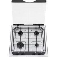
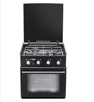
S-656 MK 12 - Cooker THETFORD - Free user manual and instructions
Find the device manual for free S-656 MK 12 THETFORD in PDF.


| Product Type | Gas Cooker |
| Brand | Thetford |
| Model | S-656 MK 12 |
| Number of Burners | 3 |
| Ignition Type | Automatic electronic ignition |
| Gas Type | LPG (butane/propane) |
| Dimensions (W x D x H) | 410 x 360 x 145 mm (approx.) |
| Cut-Out Dimensions | 382 x 332 mm |
| Weight | 6.5 kg (approx.) |
| Power Supply | 12V DC for ignition |
| Gas Connection | 8 mm hose or rigid pipe |
| Burner Output (each) | 1.0 - 2.0 kW |
| Flame Safety Device | Yes (thermocouple) |
| Control Knobs | 3 knobs with push-to-turn safety |
| Material | Stainless steel and enamel |
| Cleaning | Wipe with damp cloth, avoid abrasive cleaners |
| Intended Use | Recreational vehicles (caravans, motorhomes) |
| Certification | CE, UKCA |
| Spare Parts Availability | Through Thetford dealers and online |
Frequently Asked Questions - S-656 MK 12 THETFORD
User questions about S-656 MK 12 THETFORD
0 question about this device. Answer the ones you know or ask your own.
Ask a new question about this device
Download the instructions for your Cooker in PDF format for free! Find your manual S-656 MK 12 - THETFORD and take your electronic device back in hand. On this page are published all the documents necessary for the use of your device. S-656 MK 12 by THETFORD.
USER MANUAL S-656 MK 12 THETFORD
natural_image
Line drawing of a remote control panel with four fans and ventilation slots (no text or symbols)USER AND INSTALLATION INSTRUCTIONS
WARNING
• This appliance must be installed by an authorised person.
• Only use this appliance in a well ventilated area.
- Read the instructions before use.
FOR USE IN
GB NL DE FR ES PT IT SE NO DK SI SK
SPINFLO LIMITED, 19 Oakham Drive, Parkwood Industrial Estate
Rutland Road, Sheffield S3 9QY, ENGLAND.
TEL: +44 (0) 114 273 8157 FAX: +44 (0) 114 275 3094



In your own interest of safety, it is law that all gas appliances be installed by competent persons. CORGI (Confederation for the Registration of Gas Installers) registered installers undertake work to safe and satisfactory standards. Failure to install the appliance correctly could invalidate any warranty or liability claims and lead to prosecution. This appliance shall be installed in accordance with the local and national/European standards in force. Particular attention shall be given to the requirements regarding ventilation. Read the instructions before installing or using this appliance.
Provision of Ventilation
The use of a gas cooking appliance results in a production of heat and moisture in a room in which it is installed. Ensure that the kitchen is well ventilated: keep natural ventilation holes open or install a mechanical ventilation device, (mechanical extractor hood).
Prolonged intensive use of the appliance may call for additional ventilation, for example opening a window, or more effective ventilation, for example increasing the level of mechanical ventilation where present.
The room containing the cooker should have an air supply in accordance with local and national/European standards.
Position
This appliance must be positioned free from draughts, which may affect the combustion, and in a manner that will prevent the accumulation of unburnt gas. When in use ensure that air vents are not inadvertently blocked or shut off.
Important
This appliance is suitable for use with Liquid Petroleum Gas (LPG) and should not be used on any other gas. The following gas pressures should be used:-
CAT I 3 + (28-30/37) CAT I 3 B/P
BUTANE (G30) 28 – 30 mbar BUTANE (G30) 30mbar
PROPANE (G31) 37mbar PROPANE (G31) 30mbar
IMPORTANT
Before using the appliance for the first time, remove any surface protection film, ie plastic coating. Clean all surfaces with hot soapy water to remove any residual protective covering of oil and rinse carefully.
Using the Hob Burners
Each burner is controlled individually and is monitored by a flame failure sensing device. The respective knob positions are shown below:-
OFF
HIGH RATE
LOW RATE

natural_image
Simple circular diagram with a central vertical line and three small dots along the perimeter (no text or symbols)
natural_image
Simple circular diagram with three dots and two curved arrows, no text or symbols present.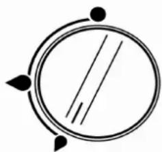
natural_image
Simple circular diagram with two parallel lines and three small dots, no text or symbols present.To light the burner, depress and turn the knob anti-clockwise to the full rate position, apply a light to the burner or press the ignition button if fitted. On models with the flame sensing device it is necessary to hold the knob depressed during ignition and for approximately fifteen seconds after the burner has lit to allow the probe to reach temperature. Should the flame go out when the knob is released, the procedure should be repeated holding the knob depressed for slightly longer. If required the knob can be turned further anticlockwise to the simmer position. To turn the burner off, rotate the knob fully clockwise until the dot on the knob lines up with the dot on the fascia.
The burners on the appliance have fixed aeration and no adjustment is required. The burners should flame as follows:-
Propane - The flames should burn quietly with a blue/green colour with no sign of yellow tips.
Butane - Normally on initial lighting, a small amount of yellow tipping will occur and then slightly increases as the burner heats up.
Using the Grill
Control of the grill burner is identical to that used for the hob burners. Although the grill does heat up quickly, it is recommended that a few minutes preheat be allowed. The grill pan should be left in position to protect the base lining and the grill door MUST be left open while the grill is in use.
A reversible grill pan trivet enables the correct grilling height to be achieved.
Fast Toasting Trivet in high position
Grilling Sausages Trivet in high position
Grilling Steak/Bacon Trivet in high position
Grilling Chops, etc Trivet in low position
Slow Cooking Trivet removed
IMPORTANT SAFETY PRECAUTIONS
- When cooking keep children away from the vicinity. Turn pan handles inwards so they cannot be caught accidentally.
- Never leave fat or oil unattended on the hotplate.
- When finished, check that all controls are in the off position.
- This appliance must not in any circumstances be used as a space heater.
LEAKS
If a smell of gas becomes apparent, the supply should be turned off at the cylinder IMMEDIATELY.
- Extinguish naked lights including cigarettes and pipes.
- Do not operate electrical switches.
- Open all doors and windows to disperse any gas escape.
- Propane gas is heavier than air, any gas escaping will therefore collect at low level. The strong unpleasant smell of gas will enable the general area of the leak to be detected. Check that the gas is not escaping from an unlit appliance.
- Never check for leaks with a naked flame, leak investigation should be carried out using a leak detector spray.
MAINTENANCE
This appliance needs little maintenance other than cleaning. All parts should be cleaned using warm soapy water. Do not use abrasive cleaners, steel wool or cleansing powders. When cleaning the burner ring it is essential to ensure that the holes do not become blocked. The control knobs are a push fit and can be removed for cleaning. They are interchangeable without affecting the sense of operation
On units fitted with battery spark ignition, when the time taken for spark generation becomes extended, the battery should be renewed with a suitable make of long life battery.
THIS APPLIANCE MUST NOT BE MODIFIED OR ADJUSTED UNLESS AUTHORISED AND CARRIED OUT BY THE MANUFACTURER OR HIS REPRESENTATIVE. NO PARTS OTHER THAN THOSE SUPPLIED BY THE MANUFACTURER SHOULD BE USED ON THIS APPLIANCE.
WHO TO CONTACT
For service, please contact your authorised local Service Agent giving full details of the model, serial number and date of purchase.
WARNINGS
- DO NOT store or use gasoline or other flammable vapours, liquids or items in the vicinity of this or any other appliance.
• DO NOT spray aerosols in the vicinity of this appliance while it is in operation. - Where this appliance is installed in marine craft or in caravans, it shall not be used as a space heater.
- NEVER check for leaks with an open flame
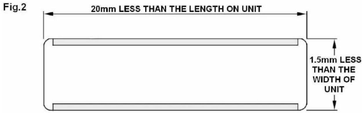
A cut-out should be prepared in the worktop as shown in Fig.2. Heat barriers must be fitted to the front and back edges of the cut-out as shown in Fig.3 - Section B-B. The appliance should be fixed in position using woodscrews fitted through the side flanges as shown.
A direct distance of 200mm must exist between the edge of the appliance burners and any combustible material, unless protected by a layer of non-combutable material. All combustible materials such as curtains and shelves must be kept well clear of the appliance. Any fitments such as a cupboard above the unit must have a minimum clearance of 500mm between the fitment and the top of the Panrest.
In the case of appliances that do not have grills fitted, the underside of the appliance must be shielded. It is recommended that the shield be fabricated from non-combustible material, but if the enclosure is manufactured from combustible material, then a minimum air space of 100mm must exist between the material and the lowest part of the appliance.
Appliances fitted with a grill require that a grill compartment be created below the cut-out as shown in Fig.4. The compartment must be completely lined with a non-combustible material such as aluminium or stainless steel. The grill compartment must have ventilation holes at the compartment floor level and additionally include an escape route to the outside to prevent the accumulation of unburnt gasses. Any cabinets beneath the grill compartment must be sealed to prevent the ingress of unburnt gas.
CONNECTION
Gas Connection
The gas connection is made to a 8mm ∅ inlet pipe, beneath and to the rear of the appliance. Prior to connection remove the plastic protection plug from the fitting. It is recommended that the appliance be connected by copper pipe, rubber tubing MUST NOT be used.
IMPORTANT
• After installation the appliance MUST be tested for soundness
- Test ALL burners on high and low flame for flame stability.
- The gas supply input pressure MUST not rise or fall significantly from nominal when ALL appliances connected to the supply are operated simultaneously. If NOT installed to the manufacturers instructions detailed herein, we the manufacturer can not be held responsible for any problems that occur, or poor performance that is perceived/witnessed.
Hob Burner Gas valve removal/replacement
- Shut off gas supply and disconnect gas supply pipe from the unit.
- Remove the hob from the bench top.
- Remove the appropriate control knob by pulling up.
- Unscrew the gas valve retaining nut.
- From the underside of the hob, unscrew the appropriate thermocouple nut at the gas valve.
- Unscrew the appropriate gas supply pipe nut.
- Remove the appropriate gas valve clamp by unscrewing the two screws.
- Remove the gas valve.
- Replace the tap and gasket. Refit using reverse procedure.
Hob Burner Injector removal/replacement
- Remove the pan support by pulling up to release it from the plastic clips.
- Remove the appropriate burner cap and skirt.
- With a 7mm A/F socket, unscrew injector from the bottom of the burner mixing tube.
- Replace/refit using the reverse procedure.
Thermocouple removal/replacement
- Shut off gas supply and disconnect gas supply pipe from the unit.
- Remove the hob from the bench top.
- Unscrew the appropriate thermocouple nut next to the burner.
- From the underside of the hob, unscrew the appropriate thermocouple nut at the gas valve.
- Remove the thermocouple.
- Replace/refit using reverse procedure.
Grill burner removal/replacement
- Shut off gas supply and disconnect gas supply pipe from the unit.
- Remove the hob from the bench top.
- Unscrew the two screws retaining the grill burner to the hob.
- From the underside of the hob, unscrew the thermocouple nut at the grill burner.
- Lift the grill burner clear of the thermocouple and injector.
- Replace/refit using reverse procedure.
Grill Injector removal/replacement
- Follow procedure to remove grill burner
- With a 7mm A/F socket, unscrew the injector from its holder.
- Replace/refit using reverse procedure.
- USER AND INSTALLATION INSTRUCTIONS
- WARNING
- Provision of Ventilation
- Position
- Important
- Using the Hob Burners
- Using the Grill
- IMPORTANT SAFETY PRECAUTIONS
- LEAKS
- MAINTENANCE
- WHO TO CONTACT
- WARNINGS
- CONNECTION
- Gas Connection
- Hob Burner Gas valve removal/replacement
- Hob Burner Injector removal/replacement
- Thermocouple removal/replacement
- Grill burner removal/replacement
- Grill Injector removal/replacement
Brand : THETFORD
Model : S-656 MK 12
Category : Cooker