
VSR Pro - Bicycle IDEAL - Free user manual and instructions
Find the device manual for free VSR Pro IDEAL in PDF.


| Product Type | Bicycle |
| Brand | Ideal |
| Model | VSR Pro |
| Frame Material | Aluminum alloy |
| Wheel Size | 29 inches |
| Weight | 14.5 kg (32 lbs) |
| Max Rider Weight | 120 kg (265 lbs) |
| Brake Type | Disc brakes (mechanical) |
| Gear System | 21-speed derailleur |
| Recommended Use | Mountain biking, recreational cycling |
| Recommended Height | 170-190 cm (5'7"-6'3") |
| Power Source | Human power |
| Assembly Required | Yes, basic assembly |
| Maintenance | Regular cleaning, lubrication, brake adjustment |
| Safety Features | Reflectors, bell, front/rear lights (optional) |
| Spare Parts Availability | Commonly available at bike shops |
| Warranty | 2 years on frame, 1 year on components |
| Country of Origin | China |
| User Manual Included | Yes, PDF format |
Frequently Asked Questions - VSR Pro IDEAL
User questions about VSR Pro IDEAL
0 question about this device. Answer the ones you know or ask your own.
Ask a new question about this device
Download the instructions for your Bicycle in PDF format for free! Find your manual VSR Pro - IDEAL and take your electronic device back in hand. On this page are published all the documents necessary for the use of your device. VSR Pro by IDEAL.
USER MANUAL VSR Pro IDEAL
natural_image
Side profile of a person riding a bicycle, wearing helmet and athletic attire (no visible text or symbols)natural_image
Close-up of a person's lower body of a bicycle with visible frame and wheel (no text or symbols)natural_image
Three black bicycle side profiles shown from top, front, and back angles (no text or symbols)natural_image
Side view of a black bicycle seat with a double-headed arrow indicating rotation (no text or symbols)natural_image
Side-by-side black-and-white photo showing a bicycle leotard with a hand adjusting the seat, no visible text or symbolsnatural_image
Close-up of a mechanical lever assembly with no visible text or symbols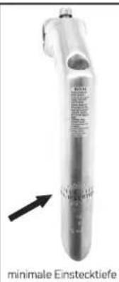
natural_image
Pure mechanical component diagram showing a spring and lever assembly (no text or symbols)natural_image
Mechanical assembly diagram showing a central shaft with flanges and mounting brackets (no text or symbols)natural_image
Close-up of a tree trunk with a black arrow pointing to it, no visible text or symbolsnatural_image
Close-up of a hand adjusting a bicycle tire component (no visible text or symbols)natural_image
Close-up of a bicycle's wheel and spokes assembly (no visible text or symbols)natural_image
Close-up of a bicycle suspension system with visible mechanical components and wiring (no text or symbols)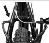
natural_image
Close-up of hands holding a bicycle tire and a bow, no visible text or symbolsnatural_image
Close-up of a bicycle wheel with visible spokes and chains (no text or symbols)natural_image
Close-up of a hand using a tool to adjust or install a bicycle wheel (no text or symbols visible)natural_image
Close-up of a hand using a bicycle to pin the wheel (no text or symbols visible)natural_image
Close-up of a bicycle wheel with a hand adjusting the rim (no visible text or symbols)natural_image
Close-up of a bicycle wheel with a hand adjusting the rim (no text or symbols visible)natural_image
Side-by-side comparison of a bicycle's seatbelt and clamp bracket (no text or symbols visible)natural_image
Close-up of a hand holding a bicycle handle and wrist strap (no text or symbols visible)natural_image
Close-up of a bicycle tire with attached brake calipers and a screwdriver (no visible text or symbols)natural_image
Close-up of a bicycle wheel and barbed wire assembly (no visible text or symbols)natural_image
Close-up of a bicycle's wheel and gear mechanism (no text or symbols visible)natural_image
Pure electrical circuit lines without any symbolsnatural_image
Two views of a mechanical component, one showing a central hub and two close-up views of a textured, textured object (no text or symbols visible)natural_image
Close-up of a bicycle wheel with a threaded connector and three vertical supports (no text or symbols visible)natural_image
Close-up of a mechanical component with a threaded end and striped surface (no visible text or symbols)natural_image
Two black rubber crumbers with hook handles, isolated on white background (no text or symbols)natural_image
Close-up of hands adjusting a bicycle tire (no text or symbols visible)natural_image
Close-up of a hand pressing down on a bicycle tire wheel (no text or symbols visible)natural_image
Anatomical line drawing of a human head and neck region with a needle inserted (no text or labels)| VORBAUTEN | |||
| Modellname | Drehmoment der Schrauben die in Bezug mit dem Lenker stehen | Drehmoment der Schrauben die in Bezug mit dem Schaft stehen | Drehmoment der Winkeleinstellschraube |
| RACE PRO TEAM | 5 Nm | 5 Nm | |
| RACE PRO 29 | |||
| TRAXER | |||
| PRISMA | |||
| BOOMMAX | |||
| TARGET | |||
| HILLMASTER | |||
| ZIGZAG | |||
| TRAXER COMP | |||
| KRITTON | |||
| ZIGZAG 29 | |||
| PRO RIDER 29 | |||
| STROKE | |||
| AXION | |||
| VSR PRO | |||
| VSR COMP | |||
| PRO RIDER | |||
| STROBE | |||
| FREEDER | |||
| MOOVIC | 14 Nm | 14 Nm | |
| TRIAL | |||
| INTEGRATOR | 5 Nm | 5 Nm | |
| ERGOMAX | |||
| FUTOUR | |||
| MULTIGO | |||
| OPTIMUS | |||
| MEGISTO | 10 Nm | 9 Nm | 18-25 Nm |
| TESTEK | |||
| UNIGO | |||
| CITY-LIFE | |||
| TRAVELON | |||
| CROSSMO | 8 Nm | 18-25 Nm | |
| NERGETIC | |||
| EZIGO | |||
| INDIGO | 11-12 Nm | 14-15 Nm | |
| CITY LIFE NEXUS 3 | |||
| STAGE TEAM | 5 Nm | 5 Nm | |
| STAGE | |||
| ON ROAD | |||
| INTEMPO | |||
| STREAMLITE | |||
| CHICANE | |||
| CITYRUN | 11-12 Nm | 14-15 Nm | 18-25 Nm |
| V-TRACK | 14-15 Nm | 14-15 Nm | |
| CITY LIFE 20 | |||
| CITY LIFE 24 | |||
| AXION 24 | 14-15 Nm | 14-15 Nm | |
| STROBE 24 | |||
| STROBE 20 | |||
| DSS 20 | 14 Nm | 14 Nm | |
| DSS 24 | |||
| CONDOR 20 | |||
| X-TEN | 18 Nm | 18 Nm | |
| X-SIX | |||
| FREILAUF | |
| Modellname | Drehmoment |
| CITY LIFE 700C | 30Nm |
| V-TRACK | |
| STROBE 20" ATB | |
| STROBE 20" | |
| STROBE 24" | |
| STROBE 24" MD | |
| STROBE 24" ATB | |
| UNIGO | |
| TRIAL | |
| MOOVIC | |
| CITY LIFE NEXUS 7 | 30-45Nm |
| CITY LIFE NEXUS 3 | |
| STROBE 24" NEXUS | |
| STROBE 20" NEXUS | |
| EZIGO NEXUS 7 | |
| EZIGO NEXUS 3 | |
| TRAVELON NEXUS 8 | |
Modell:
Kaufdatum:
Rahmenmaterial:
Rahmenfarbe:
Rahmengröße:
We strongly encourage you to take the time to read this Manual and familiarise yourself with your new bicycle. If you have purchased it for a child, please take the time to make sure the child understands the information contained in this Owner's Manual. It is essential that the parent/a responsible adultthoroughly reviews this information and reads it to the child. Even if you are an experienced cyclist, please take a moment to read through this Manual before you or your child ride.
We also strongly encourage you to have your IDEAL bicycle completely assembled from your local IDEAL bicycle dealer. This is very important for optimum performance, safety and riding joy. Any adjustments you make of your own are entirely your own risk.
It is important to understand the basics of riding a bicycle. Equally important is to exercise common sense when cycling. Like all sports, bicycling involves risk of injury and damage. By choosing to ride a bicycle, you assume the responsibility for that risk, so you need to know and constantly practice the rules of safe and responsible riding and of proper use and maintenance. Proper use and maintenance of your bicycle reduces risk of injury. But because it is impossible to anticipate every situation or condition which may occur while bicycling, this Manual makes no representation about the safe use of the bicycle under all conditions. There are risks associated with the use of a bicycle which cannot be predicted or avoided, and which are the sole responsibility of the rider.
BICYCLE SAFETY
• Respect all traffic laws.
- Ride defensively, assuming others do not see you. Never race in traffic or hitch a ride by holding on to another vehicle. When riding in traffic, watch out for cars pulling over or for parked cars; doors
may open at any time. Use approved hand signals for turning and stopping. Please note & respect the national laws concerning the use of equipped and non-equipped (e.g. lighting sets & reflectors) bicycles in public traffic.
• Always have front & rear lights on, when bicycling after sunset. Install front, rear & wheel reflectors properly and periodically check their mounting stability and surface cleanness.
• Always wear a helmet. Follow the helmet manufacturer's instructions for fit, use and care of your helmet. In case you carry a child in a baby seat, make sure the child always wears an approved helmet too.
• Always ride wearing bright, visible clothing that is not too loose. Otherwise there is danger of getting tangled with bicycle parts or objects along your trail.
• Always wear shoes that will stay on your feet and offer proper grip with pedals. Do not ride barefoot or wearing sandals. Naked parts of your body must be kept away from chain, crankset & pedals.
• Always wear protective eyewear. Bugs, dirt & dust may cause you to lose control or even hurt you. Eyewear glasses must be tinted when it is sunny and clear when it is not.
- Never ride with headphones. They cover traffic sounds and emergency vehicle sirens and they prevent you from concentrating on riding properly. Their wiring may also mess with moving parts of your bicycle, causing you to lose control.
- Ensure that the bicycle size is right for the rider, that the rider can reach the brake levers properly and that the brakes and the bicycle work absolutely well. In principle IDEAL bicycles are pre-assembled and delivered so that the right brake lever operates the rear brake and the left lever the front brake. In certain countries national laws and regulations may impose the opposite assembly either by IDEAL factory directly or by the specialized IDEAL bicycle dealer. Please check with your dealer for more details, preferably at the time the bicycle is handed over to you.
- Do not ride two people on a bicycle designed for one. In case of baby seats/carriers, make sure they are child-safety certified and properly
installed. Please note that IDEAL models falling into Mountain, All Terrain, Dirt, Full Suspension, Trekking Off-Road, Fitness, Road, Junior & Freestyle categories are not intended for the use of baby seats/carriers. IDEAL will not take any warranty or responsibility when using a baby seat/ carrier on bicycles mentioned above.
- Mount loads securely. Never carry bags, packages or other objects that may interfere with brakes or vision or may obstruct your complete bicycle control. IDEAL will not take any warranty or responsibility when using a baggage or baby carriage trailer that requires special frame and/or bicycle construction.
- Never ride in extreme weather conditions or under the influence of alcohol or drugs or any other substance. Do not perform jumps or stunts. Think very carefully about your skills and physical condition before deciding to take the bigger risks that go along with some special kinds of riding.
- Remember you are sharing the road or the path with other bikers, motorists or pedestrians. Please respect their rights.
in the field, we urge you to exercise care, and to have the fasteners you worked on checked by your dealer as soon as possible.
WARNING: Correct tightening force on fasteners -nuts, bolts, screws- on your bicycle is important. Too little force and the fastener may not hold securely. Too much force and the fastener can strip threads, stretch, deform or break. Either way, incorrect tightening force can result in component failure, which can cause you to loose control and fall.
The tables in pages 100-102 show the recommended torque values for parts which are assembled on all Ideal bicycles. Make sure nothing is loose. Lift the front wheel off the ground by 5-8cm, and then let it bounce on the ground. Anything sound, feel or look loose? Do a visual and tactile inspection of the whole bike. Have you noticed any loose parts or accessories? If so, secure them. If you're not sure, seek advice from a specialized bicycle dealer.
MECHANICAL SAFETY
Routinely check the condition of your bicycle before every ride. Nuts, bolts screws & other fasteners. Because manufacturers use a wide variety of fasteners sizes and shapes made in a variety of materials, often differing by model and component, it is not possible for this Manual to specify correct torque (tightening force) for the fasteners on your bicycle. We can tell you the importance of correct torque, but not the specific torque required for each fastener on your bicycle. To correctly torque a fastener, a torque wrench must be used. A professional bicycle mechanic with a torque wrench should torque the fasteners on your bicycle. If you choose to work on your own bicycle you must get correct tightening torque specifications from the bicycle or component manufacturer or from your specialized IDEAL bicycle dealer. If you need to make an adjustment at home or
BICYCLE FIT
Correct fit is essential for bicycling safety, comfort & performance. Making the proper adjustments to your body and riding conditions requires experience, technical skills and sometimes special tools. Always have your specialized bicycle dealer make these adjustments on your bicycle. If your bicycle does not fit properly, you may lose control and fall. If your new bicycle does not fit properly, ask your specialized IDEAL bicycle dealer to exchange it before you ride it.
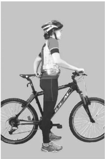
Standover height is the first & most important bike fit element. It is the distance between the ground and the frame, at the point of your crotch when straddling the bike. Standover height clearance is the distance between that frame point and your crotch. A bicycle used on-road needs a minimum standover height clearance of 5cm. A bicycle used off-road requires a minimum clearance of 10cm. Mixed use is better with 7.5cm.
natural_image
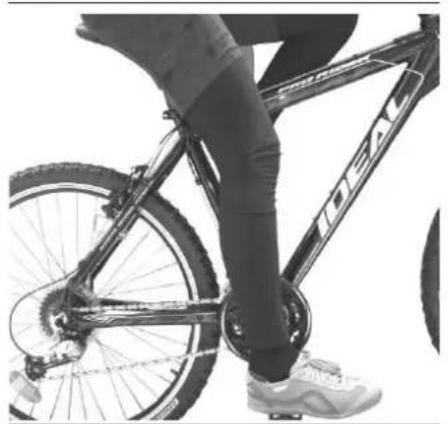
Side profile of a person riding a bicycle, wearing helmet and racing suit (no visible text or symbols)Saddle position is the second important bike fit element. The up-down saddle adjustment requires you to sit on the saddle, place your heel on the pedal, rotate the crank towards the ground until it is parallel to the seat tube, and look at the direction of your foot. If it is pointing down roughly at 30 degrees, your saddle height is correct.
natural_image
Close-up of a person riding a bicycle with visible branding and foot (no text or symbols on the bicycle body)Immediately check whether the "minimum insertion" mark on the seat post is visible.
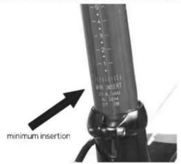
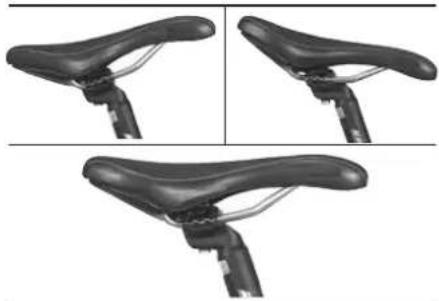
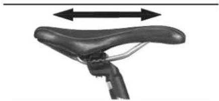
If yes, either you need a longer seat post or the standover height is not ok for your body. There are two more saddle adjustments, the front-back & the angle. Most riders prefer an angle of zero, i.e. a horizontal saddle.
natural_image
Three black bicycle wheel skis shown from top, side, and front views (no text or symbols)Front-back adjustment relates to your upper body dimensions as well as your riding style & preferred comfort.
natural_image
Side view of a black bicycle saddle with motion arrows indicating vertical motion (no text or symbols)Both these adjustments should be done the first time you ride the bicycle, with a specialized bicycle dealer who should also teach you how to do it from now on. Please note that not all seat posts and saddles accept the same adjustment method. If your bicycle
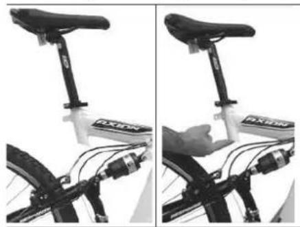
is equipped with suspension seat post, periodically ask a specialized bicycle dealer to check & service it. It is important to fasten properly the saddle on the seat post and the seat post inside the seat tube, by applying correct torque. M5 screws must be tightened with 6Nm, M8 with 20Nm. If your bicycle has an interrupted seat tube, something common
natural_image
Side-by-side black-and-white photo showing front and side views of a bicycle seat with visible branding (no text or symbols)on full suspension bicycles, make sure that your seat post is long enough so that you touch it with your finger by inserting it in the seat tube without exceeding your finger's first knuckle. If the seat post inserted into the upper seat tube is too short, there is a risk of breaking the frame. If on the contrary the seat post is too long and exits the upper seat tube, make sure there is enough clearance from the lower part of the seat tube, taking into consideration the rear shock operation & movement. There is a risk of interference between the seat post & the rear shock that may lead to an accident. If in spite of all the adjustments, your saddle still feels uncomfortable, you probably need a different saddle design. Saddles come in many different shapes, sizes and comfort levels. Please contact & consult your specialized IDEAL bicycle dealer.
Handlebar position is bike fit element number three. It depends on handlebar & stem height & angle, as well as handlebar width. These adjustments must be made by your specialized IDEAL bicycle dealer the first time you test ride the bicycle. There are numerous possibilities in the market, so even if you cannot fit properly in the bicycle cockpit, your specialized bicycle dealer can work out a solution for you. There are two types of stem available, threadless and quill.
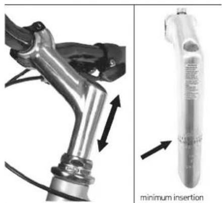
Threadless stems clamp on the outside of the fork steerer tube. The stem height may be adjusted with spacers positioned below or above the stem, along the steerer. Quill stems enter the steerer tube and tighten with an expanding bolt. Height may be adjusted by moving the quill up or down inside the steerer. One must be very careful not to exceed the "minimum insertion/extension" mark of the stem.
natural_image
Mechanical assembly diagram showing a lever mechanism and a test tube with arrows indicating force direction (no text or symbols)This mark must not be visible at any time above the top head parts, otherwise the stem may damage the fork steerer tube causing loss of control. When adjusting the stem height, please note and remember the effect on braking and transmission cables. Cables may over-extend and lock or they may create excess slack. In both cases braking and shifting may become inoperable. Please consult a specialized bicycle dealer on the effect of stem adjustments on bicycle cabling.
The last bike fit step is the position of control components, i.e. shifters and brake levers. Position on the handlebar, angle and distance from rider fingers, are all very important. At all times and riding positions the brake levers must be within reach of the rider. It is of paramount importance that all these parameters are fully adjusted by a specialized IDEAL bicycle dealer before purchasing the bicycle.
A last, separate note needs to be made for IDEAL full suspension bicycles. If your bicycle is equipped with a rear shock, please refer to the instructions of the manufacturer of the rear suspension, enclosed with the rest of documents. Safety, comfort & fun can only be guaranteed through proper adjustment of all suspension elements on your bicycle. Make sure you cooperate with a specialized IDEAL bicycle dealer for this.
OWNER'S MANUAL·81
BICYCLE CHECK
Before you ride your bicycle the first time, you must make sure it is in a safe operating condition. Below are some basic, simple, but important checks:
• Nuts, bolts and parts are tight, not worn, not damaged.
- Cables are securely fixed on the frame, without kinks.
- Brakes are operating effectively.
- Steering is free, i.e. handlebar turns without resistance, but also without excessive play.
- Wheels run true, without any kind of wobbling.
• Wheels are securely fastened to frame and fork.
• Tires are in good condition and under pressure that is within the recommended values mentioned on the tire itself.
• Pedals are securely tightened to cranks.
• Gears are correctly adjusted and shifting is according to expectations.
• Bell and lights are functioning and clean.
- Handlebar grips are tightly fixed and in good condition.
- Front and rear suspension is not loose and does not make any strange noise.
A pretty successful practical test is to lift your bike 5-8cm above the ground and then let it drop. Listen for and try to locate any strange noise. Such noises may be the start of something serious. The above checks before your first ride must be ideally done in the specialized bicycle shop where you purchase your IDEAL bicycle. After you start riding your bicycle on a regular basis, please refer to the necessary checks, maintenance and service in page 57.
BICYCLE TECH
Wheels
Riding your bicycle without properly adjusted wheels may lead the wheels to wobble or even disassemble from the rest of the bicycle, which can cause you to lose control and fall.
Your specialized IDEAL bicycle dealer must help you understand how to remove and install back safely both wheels on your bicycle.
In case your bicycle is equipped with through axle front and/or rear, please read carefully and follow the manufacturer's instructions. If you do not feel comfortable, have your specialized bicycle dealer do the job whenever you need it.
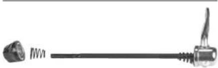
Most bicycles nowadays use quick release (QR) mechanisms.
natural_image
Pure electrical connector diagram without any text, numbers, or symbolsThese are cams that apply pressure and clamp the wheels in place on the fork (front) and the frame (rear). Holding the nut with one hand and turning the lever like a wing nut with the other hand until they both become as tight as you can do, will not be enough. In order for the QR to properly fasten the wheels, the full force of the cam action is necessary.
The wheel hub is clamped in place by the force of the quick release cam pushing against one dropout and pulling the tension adjusting nut, by way of the skewer, against the other dropout. The amount of clamping force is controlled by the tension adjusting nut. Turning the tension adjusting nut clockwise while keeping the cam lever from rotating increases clamping force; turning it counterclockwise while keeping the cam lever from rotating reduces clamping force. Less than half a turn of the tension adjusting nut can make the difference between safe clamping force and unsafe clamping force.
Most bicycles have front forks which utilize a secondary wheel retention device to reduce the risk of the wheel disengaging from the fork if the quick release is incorrectly adjusted. Secondary retention devices are not a substitute for correct quick release adjustment. Secondary retention devices fall into two basic categories: (1) The clip-on type is a part which the manufacturer adds to the front wheel hub or front fork. (2) The integral type is molded, cast or machined into the outer faces of the front fork dropouts. Ask a specialized bicycle dealer to explain
the operation of the particular secondary retention device on your bike. Do not remove or disable the secondary retention device. As its name implies, it serves as a back-up for a critical adjustment. If the quick release is not adjusted correctly, the secondary retention device can reduce the risk of the wheel disengaging from the fork. Removing or disabling the secondary retention device may also void the warranty.
Removing a Quick Release Front Wheel
If your bike has a front disc brake, exercise care when touching it. Discs have sharp edges and can get very hot during use.
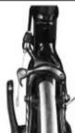
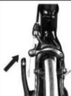
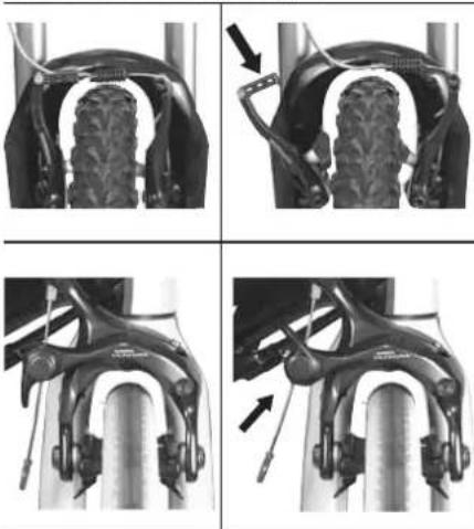
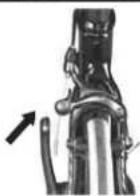
If your bike has rim brakes, disengage the brake's quick-release mechanism to increase the clearance between the rim and the brake pads.
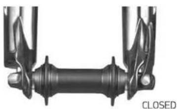
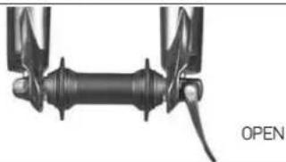
Move the wheel's quick-release lever from the locked or CLOSED position
natural_image
Mechanical assembly diagram showing a central shaft with flanges and housing (no text or symbols)to the OPEN position.
natural_image
Mechanical component diagram showing a shaft and mounting bracket with no visible text or symbolsIf your front fork has a clip-on type secondary retention device, disengage it. If your front fork has an integral secondary retention device, loosen the tension adjusting nut enough to allow removing the wheel. Lift the front wheel a few cm above the ground and tap the top of the wheel with the palm of your hand to release the wheel from the front fork.
Installing a Quick Release Front Wheel
If your bike is equipped with disk brakes, be careful not to damage the disk, caliper or brake pads when re-inserting the disk into the caliper. Never activate a disk brake's control lever unless the disk is correctly inserted in the caliper.
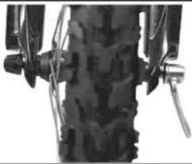
Move the quick-release lever so that it curves away from the wheel.
natural_image
Close-up of a mechanical component with textured surface and mounting brackets (no visible text or symbols)This is the OPEN position. With the steering fork facing forward, insert the wheel between the fork blades so that the axle seats firmly at the top of the slots which are at the tips of the fork blades — the fork dropouts. The quick-release lever should be on the left side of the bicycle.
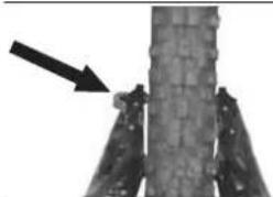
natural_image
Close-up of a tree trunk with a black arrow pointing to it, no visible text or symbolsOWNER'S MANUAL·83
Some front disc brake equipped bicycles present the quick-release lever on the right side, to avoid proximity with the disc brake rotor.
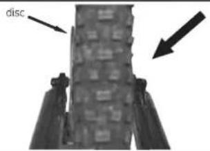
If your bike has a clip-on type secondary retention device, engage it. Holding the quick-release lever in the OPEN position with one hand, tighten the tension adjusting nut with your other hand until it is finger tight against the fork dropout.
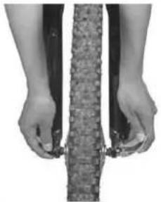
natural_image
Close-up of hands holding a textured cylindrical object, possibly a mechanical or electronic component (no visible text or symbols)While pushing the wheel firmly to the top of the slots in the fork dropouts, and at the same time centering the wheel rim in the fork, move the quick-release lever upwards and swing it into the CLOSED position.
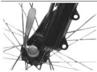
natural_image
Close-up of a mechanical component with intersecting lines and a central knob (no visible text or symbols)CLOSED
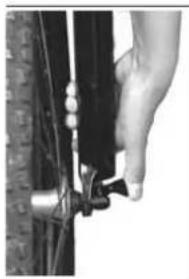
The lever should now be parallel to the fork blade and curved toward the wheel. To apply enough clamping force, you should have to wrap your fingers around the fork blade for leverage, and the lever should leave a clear imprint in the palm of your hand. If this does not happen, open the lever again,
natural_image
Close-up of a hand adjusting a bicycle tire component (no visible text or symbols)turn the tension adjusting nut clockwise a quarter turn and then try again. If the opposite happens, i.e. the lever cannot be pushed all the way parallel and near the fork blade, return to OPEN position, turn the tension adjusting nut counterclockwise a quarter of a turn and try tightening the lever again. If your bike
has rim brakes re-engage the brake quick release mechanism to restore correct brake pad-to-rim clearance, rotate the wheel to check if it is centered in the fork and clears the brake pads, and press the brake levers to make sure front brakes operate efficiently.
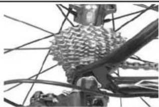
Removing a Quick Release Rear Wheel Shift the rear derailleur to the smallest, outer rear sprocket; this is the high gear position.
natural_image
Close-up of a bicycle's wheel and spokes assembly (no visible text or symbols)If your bike has rim brakes, disengage the brake's quick-release mechanism to increase the clearance between the rim and the brake pads.

natural_image
Close-up of a mechanical assembly with springs and gears (no visible text or symbols)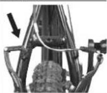
natural_image
Close-up of a mechanical assembly with rods and a gear mechanism (no visible text or symbols)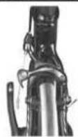
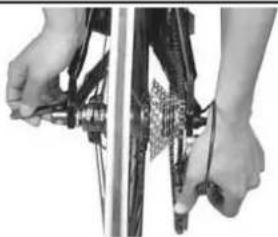
Pull the derailleur body back with one hand and move the wheel's quick-release lever to the OPEN position with the other hand.
natural_image
Close-up of hands holding a bicycle tire with visible mechanical components (no text or symbols)Lift the rear wheel a few cm above the ground and, with the derailleur body pulled back, push the rear wheel forward and down until it comes off the frame rear dropouts.
Installing a Quick Release Rear Wheel If your bike is equipped with disk brakes, be careful not to damage the disk, caliper or brake pads when re-inserting the disk into the caliper. Never activate a disk brake's control lever unless the disk is correctly inserted in the caliper.
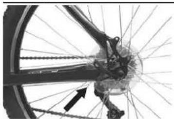
Make sure the rear derailleur is still to the high gear position. Pull the derailleur body back with your right hand and move the wheel's quick-release lever to the OPEN position. The quick release lever must be on the side of the wheel that is opposite to the derailleur and sprockets. However, if your bike is equipped with a rear disc brake the quick release lever must be on the right side. Put the chain on top of the smallest sprocket, insert the wheel into the frame rear dropouts and pull the wheel tight all the back and into the dropouts. Tighten the quick-release adjusting nut until it is finger tight against the frame dropouts, swing the lever toward the front of the bike until it is parallel to the frame's chainstay or seatstay and is curved toward the wheel.
natural_image
Close-up of a bicycle wheel with visible spokes and a gear mechanism, no text or symbols presentTo apply enough clamping force, you should have to wrap your fingers around the chainstay or seatstay for leverage, and the lever should leave a clear imprint in the palm of your hand. If this does not happen, open the lever again, turn the position adjusting nut clockwise a quarter turn and then try again. The rear wheel must be secured to the bicycle frame with sufficient force so that it cannot be pulled forward by the chain, even under the greatest pedaling force. If the wheel moves under pedaling force, the tire can touch the frame, which can cause you to lose control and fall. If the lever cannot be pushed all the way to a position parallel to the chainstay or seatstay tube, return the lever to the OPEN position. Then turn the adjusting nut counterclockwise one-quarter turn and try tightening again. If your bike has rim brakes re-engage the brake quick-release mechanism to restore correct brake pad-to-rim clearance; spin the wheel to make sure that it is centered in the frame and clears the brake pads; then press the brake lever and make sure that the rear brakes are operating correctly.
natural_image
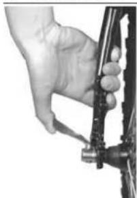
Close-up of a hand using a tool to adjust or install a bicycle wheel (no text or symbols visible)Removing a Bolt-On Front Wheel
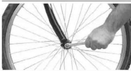
If your bike has rim brakes, disengage the brake's quick-release mechanism to increase the clearance between the rim and the brake pads. Using a correct size wrench, loosen the two axle nuts. If your front fork has a clip-on type secondary retention device, disengage it. If your front fork has an integral secondary retention device, loosen the axle nuts enough to allow wheel removal. Lift the front wheel a few cm above the ground and tap the top of the wheel with the palm of your hand to release the wheel from the front fork.
Installing a Bolt-On Front Wheel
To install back into place a bolt on front wheel, do the following. With the steering fork facing forward, insert the wheel between the fork blades so that the axle seats firmly at the top of the slots which are at the tips of the fork blades. The axle nut washers
OWNER'S MANUAL·85
should be on the outside, between the fork blade and the axle nut. If your bike has a clip-on type secondary retention device, engage it. While pushing the wheel firmly to the top of the slots in the fork dropouts, and at the same time centering the wheel rim in the fork, use the correct size wrench to tighten the axle nuts enough so that the wheel stays in place, then use a wrench on each side to tighten the nuts very tightly.
natural_image
Close-up of a hand adjusting bicycle wheel spokes (no text or symbols visible)Re-engage the brake quick-release mechanism to restore correct brake pad-to-rim clearance; spin the wheel to make sure that it is centered in the frame and clears the brake pads; then pull the brake lever and make sure that the brakes are operating correctly.
Removing a Bolt-On Rear Wheel
If your bike is equipped with an internal gear rear hub, do not attempt to remove the rear wheel. The removal and re-installation of internal gear hubs require special knowledge. Incorrect removal or assembly can result in hub failure, which can cause you to lose control and fall. Furthermore, such hubs are quite expensive to service & replace.
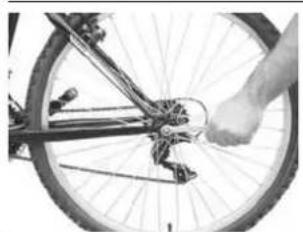
Shift the rear derailleur to the smallest, outer rear sprocket; this is the high gear position. If your bike has rim brakes, disengage the brake's quick-release mechanism to increase the clearance between the rim and the brake pads. Using a correct size wrench, loosen the two axle nuts.
natural_image
Close-up of a bicycle wheel with a hand pressing a foot (no visible text or symbols)Lift the rear wheel a few cm above the ground and, with the derailleur body pulled back, push the rear wheel forward and down until it comes out of the frame rear dropouts.
Installing a Rear Bolt-On Wheel
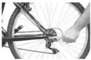
Make sure the rear derailleur is still to the high gear position. Pull the derailleur body back with your right hand and put the chain on top of the smallest sprocket, insert the wheel into the frame rear dropouts and pull the wheel tight all the way back and into the dropouts. The axle nut washers should be on the outside, between the frame and the axle nut. Using the correct size wrench, tighten the axle nuts enough so that the wheel stays in place, then use a wrench on each side to tighten the nuts very tightly.
natural_image
Close-up of a bicycle wheel with a hand pressing a tire (no visible text or symbols)Re-engage the brake quick-release mechanism to restore correct brake pad-to-rim clearance; spin the wheel to make sure that it is centered in the frame and clears the brake pads; then press the brake lever and make sure that the rear brakes are operating correctly.
Seat Post Quick Release
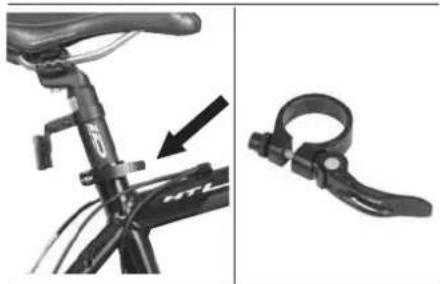
Most bicycles nowadays are equipped with a quick release seat post clamp.
natural_image
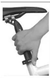
Side-by-side comparison of bicycle frame and clamp mechanism (no text or symbols visible)This works exactly like the wheel quick release and uses a cam action to firmly clamp the seat post inside the frame seat tube. The amount of clamping force is controlled by the tension adjusting nut. Turning the tension adjusting nut clockwise while keeping the cam lever from rotating increases clamping force; turning it counterclockwise while keeping the cam lever from rotating reduces clamping force. Less than half a turn of the tension adjusting nut can make the difference between safe and unsafe clamping force. The full force of the cam action is needed to clamp the seatpost securely. Holding the nut with one hand and turning the lever like a wing nut with the other hand until everything is as tight as you can get it will not clamp the seatpost safely. If you can fully close the quick release without wrapping your fingers around the seat post or a frame tube for leverage.
natural_image
Close-up of a hand holding a black tool, possibly a manual or mechanical device (no visible text or symbols)and the lever does not leave a clear imprint in the palm of your hand, the tension is insufficient. Open the lever: turn the tension adjusting nut clockwise a quarter turn; then try again.
Riding with an improperly tightened seat post can allow the saddle to turn or move and cause you to lose control and fall.
Ask a specialized bicycle dealer to help you make sure you know how to correctly clamp your seat post. Understand and apply the correct technique for clamping your seat post quick release. Before you ride your bicycle, first check that the seatpost is securely clamped.
Brakes
Your IDEAL bicycle is equipped with reliable and well-functioning brakes, provided they are correctly adjusted and maintained. Riding with improperly adjusted brakes or worn brake pads is extremely dangerous and can result in serious injury.
Applying brakes too hard or too suddenly can lock up a wheel, which could cause you to lose control and fall. Sudden or excessive application of the front brake may pitch the rider over the handlebars, which may result in serious injury.
Some bicycle brakes, such as disc brakes and linearpull brakes, are extremely powerful. Take extra care in becoming familiar with these brakes and exercise particular care when using them.
Disc brakes can get extremely hot with extended use. Be careful not to touch a disc brake until it has had plenty of time to cool.
See the brake manufacturer's instructions for operation and care of your brakes. If you do not have the manufacturer's instructions, see a specialized IDEAL bicycle dealer or contact the brake manufacturer.
Brake Controls
Your IDEAL bicycle is pre-assembled and delivered so that the right brake lever operates the rear brake and the left lever the front brake, unless there is a national law or regulation imposing the opposite. It is very important for your safety that you understand and remember which brake lever controls which brake on your bicycle.
Your hands must be able to reach and pull the brake levers comfortably. If this is not the case, check with a specialized bicycle dealer. Most brake levers can adjust their reach position. So either your brake levers need reach adjustment or you need a different brake lever design.
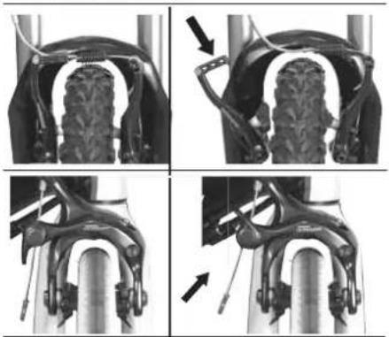
Most rim brakes nowadays have some form of quick release mechanism which clears the brake pads from the wheel rim, so that the wheel can easily be removed or re-installed.
OWNER'S MANUAL·87
When the brake quick release is open, the brakes are inoperative. Make sure a specialized bicycle dealer explains to you how the brake quick release works on your bike. Always make sure both brakes work correctly, before you start your ride.
Brakes Operation
Brakes are first designed to control the speed of vehicles and then to stop them. The maximum braking force occurs right before the wheel locks (e.g. stops rotating) and starts to skid. If and when the wheel skids, the rider has lost most of the stopping power and all of the direction control. It is very useful to practice progressive slowing and stopping of the bicycle, without locking the wheels. This is mostly a matter of experience, but a good rule of thumb is to experiment with the force you apply on the brake levers at different speeds and on different terrains. The moment you feel the wheel locks, release pressure just a little bit to keep the wheels turning. Locking the front wheel is extremely dangerous and can send you flying over the handlebar.
Another equally important parameter is your body weight transfer. When you apply the brakes and the bicycle starts to slow down, your body wishes to keep moving on and most of your weight is transferred to the front wheel. The heavier the wheel the more difficult stops. This is getting worse when your bicycle is equipped with front suspension. The suspension element "dips" under braking and worsens the weight transfer to the front. There is only one solution to this problem, which is again related to experience. You must practice, experiment and eventually learn to shift your body backwards while braking. This is even more important when you ride descents, because there automatically your weight shifts forward, even without braking.
Remember that braking gets weak on loose surfaces and in wet weather. Tire grip is reduced and brake pads get moisture. There is only one way to brake safely in such conditions and this is to ride slower. Always remember that in wet conditions braking distance is approximately 60% longer than dry weather.
Brakes Tech
There are a number of different braking systems available nowadays for bicycles. Hydraulic disc brakes, mechanical/cable disc brakes, linear pull brakes (a.k.a. v-brakes), calliper brakes, cantilever brakes, roller brakes and coaster brakes are the most common.
There is a lot of technology, maintenance and adjustment technique behind each one of these braking systems. Together with your IDEAL bicycle you must have received detailed manufacturer's instructions for your bike brakes. If not, contact your specialized IDEAL bicycle dealer immediately. In principle all adjustments and maintenance should be done by a specialized IDEAL bicycle dealer and service shop. You must only get involved with brakes service, maintenance and adjustment if you feel absolutely confident with your knowledge and practice level and always in cooperation with your specialized bicycle dealer in case of any questions.
Some useful tips in case you do decide to 'work' on your bicycle brakes.
• Disc brakes require 30 to 100 brakings to reach their maximum braking performance.
- Disc brake rotors must be as clean as possible. Never touch them with greasy hands or apply any kind of lubricant on them.
- The clearance between wheel rims and brake pads/shoes must be 1.5 to 2mm for v-brakes and 3 to 4mm for calipers.
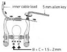
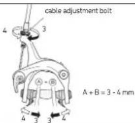
- Brake pads clearance can usually be adjusted with a cable adjustment bolt, right above the brake body.
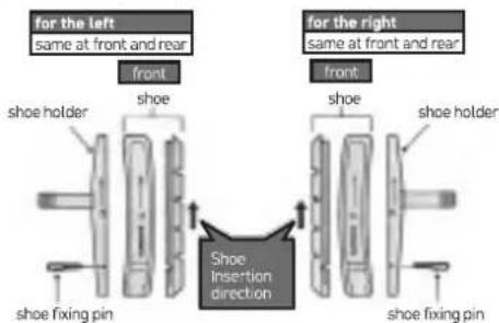
- Beware of the mounting direction arrow on the new brake shoe, whenever you replace worn brake shoes.
• Right and left brakes use different brake shoes and brake holders.
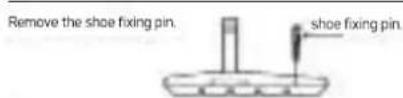
• Good quality brake shoes usually have security fixing pins. Make sure you remove them prior to brake shoe replacement and that you firmly put them back into place.
There are two different types of shoe and shoe holder to be used in the left and right positions respectively. Slide the new shoes into the grooves on the shoe holders while taking note of the correct directions and pin hole positions.
Insertion of shoe fixing pin is very critical to keep shoe properly fixed in place
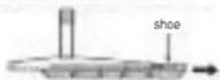
Remove the shoe by sliding it along the groove of the shoe holder.
Brakes & Rims
Linear pull brakes or v-brakes, calliper brakes and cantilever brakes apply braking force on the wheel rim. This friction based braking wears out both the brake pad/shoe and the wheel rim. The rim wear out is quicker when riding in dirty, wet and/or muddy conditions, since the brake pads then carry along various substances that hurt the rim.
All IDEAL bicycles are equipped with rims that warn the rider when they approach the end of their functional life. This is done with the so called wear out indicator. Please ask a specialized bicycle dealer to show ® explain to you this indicator, since different rim producers use different technologies for that. Furthermore, make sure your rims are checked periodically and replaced immediately if necessary. Rim failure may lead to serious accidents.
Transmission Tech
Almost all IDEAL bicycles nowadays are equipped with multiple gears. Gears have been adjusted by IDEAL during production and must be rechecked by the specialized IDEAL bicycle dealer where you purchase your bicycle, before delivery. So no [re]adjustment will be necessary to begin with. Nevertheless, it is advisable to regularly check yourself the proper shifting performance and either readjust yourself or have your bicycle serviced at a specialized bicycle shop. Together with your IDEAL bicycle you must receive detailed manufacturer's instructions for all your bicycle transmission components. If not, contact your specialized IDEAL bicycle dealer immediately to get them.
What follows is a shifting technology briefing that will familiarize you with what you will read in these detailed manufacturer's instruction leaflets. Your multi-speed bicycle will have a derailleur drivetrain, an internal gear hub drivetrain, or, in some special cases, a combination of the two.
natural_image
Mechanical assembly diagrams showing rear and front views of a bicycle gear system (no text or symbols)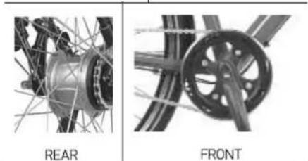
natural_image
Two technical diagrams showing front and rear views of a bicycle wheel assembly (no text or symbols present)OWNER'S MANUAL • 89
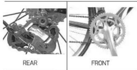
In case of a derailleur drivetrain, transmission will
REAR
natural_image
Mechanical gear assembly with chain links and pulley (no visible text or symbols)FRONT
include a rear cassette or freewheel sprocket, a rear derailleur, a front derailleur (most of the times), one or two shifters, one, two or three front sprockets (a.k.a. chainrings or chainwheels) and a chain.
Shifters may be thumb levers, twist grips, finger operated triggers, combination shift/brake controls and push-buttons. If their operation does not come naturally to you, please ask a specialized bicycle dealer to explain the type of shifting controls that are on your bike, and to show you how they work.
Shifting jargon may be confusing sometimes. A downshift is a shift to a "lower" or "slower" gear, one which is easier to pedal.
An upshift is a shift to a "higher" or "faster", harder to pedal gear.
The confusing part is most often that what's happening at the front derailleur is the opposite of what's happening at the rear derailleur. Most of the times downshifting the chain moves to a bigger sprocket at the rear and/or a smaller sprocket at the front.
The opposite happens when upshifting.
Upshifting at the rear derailleur.
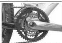
Upshifting at the front derailleur.
Whether down-or-up-shifting, the bicycle derailleur system requires the chain to move forward and be under some tension. Derailleurs shift only if and when you pedal forward. The rear derailleur is
controlled by the right shifter, the front by the left.
Never move the shifter while pedaling backwards and never pedal backwards right after moving the shifter. The chain may jam, damage the bicycle and cause you to lose control and fall off the bicycle.
Never shift a derailleur onto the largest or the smallest sprocket if the derailleur is not shifting smoothly. The derailleur may be out of adjustment and the chain could jam, causing you to lose control and fall.
To avoid excessive wear and damage of the chain, sprockets and chain wheels, we advise against the following combinations:
– Largest chainring (front) – largest sprocket (rear)
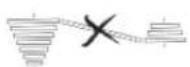
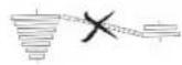
- Smallest chainring (front) - smallest sprocket (rear)
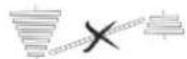
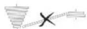
If your bicycle has an internal gear hub drivetrain, the gear changing mechanism will consist of a 3,7 or possibly 8 speed internal gear hub, one or sometimes two shifters, one or two control cables, one front sprocket called chainring or chainwheel, and a chain.
Shifting with an internal gear hub drivetrain is simply a matter of moving the shifter to the indicated position for the desired gear. After you have moved the shifter to the gear position of your choice, ease the pressure on the pedals for one or two seconds, to allow the hub to complete the shift.
Regularly check that your chain is clean and well-lubricated. Have a specialized bicycle dealer check the chain for wear.
Transmission Fit
The numerically lowest gear (1) is suitable for going uphill. The numerically largest gear (3, 5, 6, 7, 8, 9, 10 or 12) is suitable for greater speed.
It is not necessary to shift gears in sequence.
Instead, find the "starting gear" for the conditions — a gear which is hard enough for quick acceleration but easy enough to let you start from a stop without wobbling — and experiment with upshifting and downshifting to get a feel for the different gears. At first, practice shifting where there are no obstacles, hazards or other traffic, until you've built up your confidence. Learn to anticipate the need to shift, and shift to a lower gear before it gets too steep. If you have difficulties with shifting, the problem could be mechanical adjustment. See a specialized bicycle dealer for help.
Pedals
Some bicycles are equipped with pedals that have sharp and potentially dangerous surfaces. These surfaces are actually designed to increase safety by offering more grip to the rider's shoe. If your bicycle has this type of high-performance pedal, you must take extra care to avoid injury from the pedals' sharp surfaces. Based on your riding style or skill level, you may prefer a simpler pedal design. Ask a specialized bicycle dealer for help & recommendations.
Some IDEAL bicycles may be equipped with pedals that have toeclips and straps. These are ways to keep feet correctly positioned and engaged with the pedals. The toeclip positions the ball of the foot over the pedal spindle, thus maximizing pedaling power. The toe strap, when tightened, keeps the foot engaged throughout the rotation cycle of the pedal. Getting into and out of pedals with toeclips and straps requires skill which can only be acquired with practice.
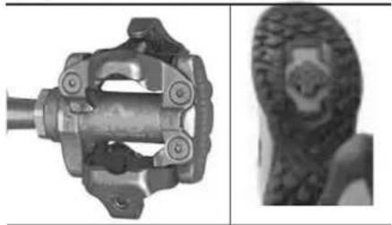
Clipless pedals are another way to keep feet securely in the correct position for maximum pedaling efficiency. They have a plate called "cleat" on the sole of the shoe, which clicks into a mating spring-loaded fixture on the pedal
natural_image
Mechanical component with two views: top shows a mechanical assembly with mounting holes, bottom shows a textured circular object (no text or symbols visible)They only engage or disengage with a very specific
motion which must be practiced until it becomes automatic. Clipless pedals require shoes and cleats which are compatible with the make and model pedal being used. Many clipless pedals are designed to allow the rider to adjust the amount of force needed to engage or disengage the foot. Follow the pedal manufacturer's instructions, or ask a specialized bicycle dealer to show you how to make this adjustment. Use the easiest setting until engaging and disengaging becomes a reflex action, but always make sure that there is sufficient tension to prevent unintended release of your foot from the pedal. Practice is required to learn to engage and disengage the foot safely. Until engaging and disengaging the foot becomes a reflex action, the technique requires concentration which can distract your attention and cause you to lose control and fall. Practice engaging and disengaging clipless pedals in a place where there are no obstacles, hazards or traffic; and be sure to follow the pedal manufacturer's setup and service instructions. If you do not have the manufacturer's instructions, see a specialized IDEAL bicycle dealer or contact the manufacturer.
Toe Overlap occurs when one of the pedals is in the most forward position, you turn the handlebar to steer, and your toe touches the front wheel. This is common on small-size or super-compact-geometry frames, and can be avoided by keeping the inside pedal up and the outside pedal down when making sharp turns. On any bicycle, this technique will also prevent the inside pedal from striking the ground in a turn. Toe Overlap could cause you to lose control and fall. Ask a specialized bicycle dealer to help you determine if the combination of frame size, crank arm length, pedal design and shoes you will use results in pedal overlap. Please note that whether you have overlap or not, you must always keep the inside pedal up and the outside pedal down when making sharp turns.
Bicycle Suspension
Most IDEAL bicycles are equipped with suspension systems. There are many different types of suspension systems. If your bicycle has a suspension system of any kind, be sure to read and follow the suspension manufacturer's setup and service instructions. If you do not have the manufacturer's instructions, see see a specialized IDEAL bicycle dealer or contact the manufacturer. Failure to maintain, check and
OWNER'S MANUAL·91
properly adjust the suspension system may result in suspension malfunction, which may cause you to lose control and fall.
Changing suspension adjustment can change the handling and braking characteristics of your bicycle. Do not change suspension adjustment unless you are thoroughly familiar with the suspension system manufacturer's instructions and recommendations. Always check for changes in the handling and braking characteristics of the bicycle after a suspension adjustment by taking a careful test ride in a hazard-free area.
Suspension can increase control and comfort by allowing the wheels to better follow the terrain. This enhanced capability may allow you to ride faster; but you must not confuse the enhanced capabilities of the bicycle with your own capabilities as a rider. Increasing your skill will take time and practice.
Tires & Tubes
The size and pressure rating are clearly marked on the sidewall of your IDEAL bicycle tires. Tire pressure is the most important piece of information. Never inflate your tires beyond the maximum pressure marked on their sidewall. Exceeding this maximum pressure may blow the tire off the rim. This may cause damage to the bike and injury to you and bystanders. The best way to inflate your tires is with a bicycle pump which has a built-in pressure gauge. Using petrol station air hoses or other air compressors is not recommended for bicycle tires, since they may rapidly increase the tire pressure causing the tube to explode.
Usually tire pressure is given on the tire sidewall as a pressure range. This is because the tire performance on different terrains and weather conditions depends on the tire pressure. Inflating the tire near its maximum pressure minimizes rolling resistance, but only works properly on smooth, dry pavement. Near the minimum allowed pressure the tire behaves very well on smooth, slick terrain like hard-packed clay, or on deep, loose surfaces like sand. But if tire pressure is too low for your weight, the possibility for pinch flats increases. This happens when the tire deforms enough to block the tube between the rim and the riding surface. The tube then punctures. A common, simplified rule of thumb requires higher pressure for heavier riders and smoother tracks, lower pressure for better shock absorption and harder terrains.
Sometimes on the tire sidewall there is another marking showing the rotation direction. This is most common on high end tires whose tread is best designed for unidirectional use, i.e. performs better when rotating in one direction only. Make sure your tires are always mounted according to the rotation direction marked on their sidewall.
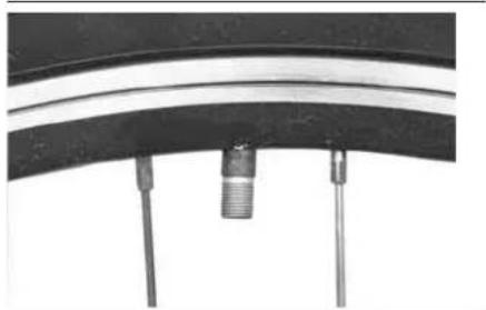
Most bicycles nowadays use two kinds of bicycle tube valves, the Schraeder and the Presta. The Schraeder valve is like the car tire valve.
natural_image
Close-up of a bicycle wheel with a threaded connector and two vertical supports (no text or symbols visible)To inflate it you need to remove the cap and clamp the pump fitting onto the end of the valve stem. To let air out you need to press the pin in the middle of the valve stem with a sharp object.
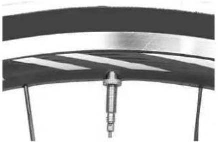
The Presta valve is narrower. To inflate it
natural_image
Close-up of a mechanical component with a curved surface and striped pattern, mounted on a stand (no visible text or symbols)remove the cap, unscrew the valve stem lock-nut counterclockwise and push down on the valve stem to help it move freely. Apply the pump head on the valve head and inflate. To let air out you need to unscrew the lock nut and press the valve stem. If your pump does not have a Presta specific head, you need an adaptor which screws on the Presta valve once
you have released the valve lock nut.
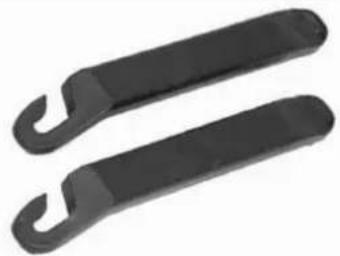
Please remember that tube patching is only an emergency and thus temporary repair. You must replace a patched tube as soon as possible with a new one. A patched tube may fail resulting in tube failure and flat tire, which may cause you to lose control and fall. In case of a flat tire, remove the wheel and deflate it completely. Unhook the tire from the rim and remove it using proper tire levers,
natural_image
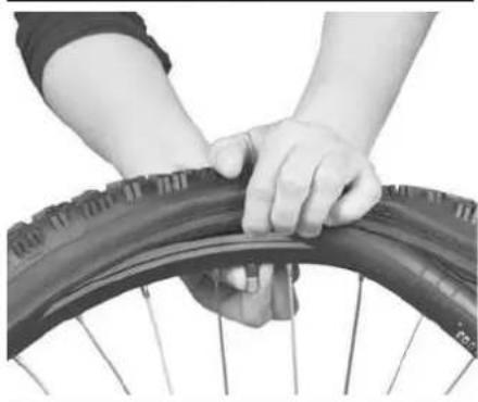
Two black rubber clips with curved handles, isolated on white background (no text or symbols)not screwdrivers or kitchenware. Remove the tube from the tire casing and replace or repair it. Slightly inflate the tube, so that it takes its round shape and put it back into the tire casing. Pass the tube valve through the rim hole and install one side of the tire bead along the rim. Using the same tire levers, preferably two of them, install the other side of the tire bead starting from the valve area and moving with the tools simultaneously to opposite sides, ideally the levers will end their way putting the tire bead back into the rim at the opposite side of the valve. Push the valve back into the tire and pull it outwards to seat on the rim properly.
natural_image
Close-up of hands adjusting a bicycle tire (no text or symbols visible)Make sure the tube does not get pinched under the
tire bead. Inflate the tube to proper pressure and close the valve cap. In case of tires with wire bead, it will be quite hard to reinstall the tire back into the rim. Be careful not to hurt your fingers and/or hands. Install the wheel back onto the frame/fork and remember to properly close the brake quick release mechanism.
In case of tubeless wheels/rims and tires, please read carefully the manufacturer's instructions for air pressure and fixing flats.
BICYCLE SERVICE
Like any mechanical device, a bicycle and its components are subject to wear and stress. Different materials and mechanisms wear or fatigue from stress at different rates and have different life cycles. If a component's life cycle is exceeded, the component can suddenly and catastrophically fail, which can cause the rider to lose control and fall. Scratches, cracks, fraying and discoloration are signs of stress-caused fatigue and indicate that a part is at the end of its useful life and needs to be replaced. While the materials and workmanship of your bicycle or of individual components may be covered by a warranty for a specified period of time by the manufacturer, this is no guarantee that the product will last the term of the warranty. Product life is often related to the kind of riding you do and to the treatment to which you submit the bicycle. The bicycle's warranty is not meant to suggest that the bicycle cannot be broken or will last forever. It only means that the bicycle is covered subject to the terms of the warranty.
Numerous advances over the last 20 years have turned bicycles into complex technological products. Bicycle service thus requires special tools, know-how and a lot of experience. It is not possible for this user Manual to provide all the necessary information and knowledge, to properly repair or even to fully maintain your IDEAL bicycle. This Manual limits itself only to the absolutely necessary things that you need to do on your bicycle for everyday use. For full periodic check & maintenance, as well as for preparation of your bicycle for a more serious event or race, it is of paramount importance that you take it to a specialized IDEAL bicycle dealer. It
OWNER'S MANUAL·93
is also strongly advisable, together with your dealer, to go through the normal maintenance requirements and adapt them to your specific riding style and even your specific geographic location where you typically use your IDEAL bicycle. This way the risk of accidents and possible injuries will be minimized.
Always remember that most bicycle service and repair tasks require special knowledge and tools. Do not begin any adjustments or service on your bicycle until your dealer has exhibited and taught you how to properly complete them. Improper adjustment or service may result in damage to the bicycle or can cause you to lose control and fall. If you want to learn to do major service and repair work on your bike, please talk to our IDEAL bicycle dealer and make sure you understand the skills it takes and the risks it encloses.
For buyingspare parts you are strongly recommended to visit your specialized IDEAL bicycle dealer where you sourced the bicycle and look for genuine, original components, preferably of the same or better level than the ones originally on your bicycle. In case you wish to differentiate, always consult a specialized bicycle dealer. IDEAL will not be responsible for damages caused by using non-original parts or parts not approved by a specialized bicycle dealer.
Original parts are extremely important for your safety when they concern frame and fork, brakes, tires and tubes, handlebar and stem, and transmission. Never use adapters to fix or assemble on your own brakes, seat posts, handlebars and stems.
BICYCLE CARE
The proper function and nice look of your IDEAL bicycle is better guaranteed if you perform some basic periodical bicycle care. This preserves the value of the bicycle and prevents corrosion or other age/time damages. Some useful tips:
- Wash with water, clean with soft brush, wipe with soft towel. Do not use high pressure water, since it may damage bearings, color and decals.
- Do not use aggressive cleaning ingredients &
additives. The nature of effects will be similar to high pressure water, but much worse.
• Repair color damages at once, before corrosion starts acting.
- Grease or oil all metal parts especially during winter use.
- Please look for and use environment-friendly, biodegradable bicycle cleaners and degreasers. Look for them at a specialized bicycle dealer.
BICYCLE MAINTENANCE, CHECK & SERVICE
At least on an annual basis, the following checks ② actions must be taken by a professional bicycle mechanic in a specialist bicycle dealer shop.
- Chain wear and tension, chain cleaning & lubrication. The bicycle chain must not be over greased. Replace if necessary.
- Headset and bottom bracket cartridge for play. Replace if necessary.
- Pedal bearings for play. Replace if necessary.
- Front & rear derailleurs for perfect function. Readjust & clean if necessary.
- Handlebar & stem for visible damages. Replace if necessary. Retighten all bolts following the recommended torque values.
- Complete brake system for perfect function. Replace defective or worn out parts, such as brake shoes, brake pads or brake cables and inner wires. Check for air in hydraulic brake systems. Refill with the proper oil if necessary.
- Complete wheels. Particular attention on rims, tires and tubes wear. Replace if necessary, and true the wheel before letting the bicycle ride again. Check hub axle for play & lubrication.
• Air pressure of the tire tubes and overall condition of the tire sidewalls and treads.
- Complete lighting system. Replace wiring if damaged or bent.
• Bell.
- Handlebar grips for proper fixing on handlebar. Replace if damaged.
- Front suspension for perfect function and play in the bushings.
- Rear suspension for perfect function and proper tightening of all bolts, according to manufacturer's recommended torque values.
- Frame and fork, if rigid, for perfect condition. Replace if something is or seems wrong.
On a monthly basis, do the following checks:
- Clean, lubricate and if necessary adjust the front & rear derailleurs.
- Clean, lubricate and if necessary tighten the head set.
- Check, grease and if necessary replace the brake & gear cables.
It is strongly advised that you have those checks done at a specialized IDEAL bicycle shop. If after the above checks you feel something is wrong or you sense/see/hear something that you do not know or like, please immediately take your bicycle to a specialized IDEAL bicycle shop.
Every 3 to 5 hours of riding, depending how hard riding has been, please perform the following checks:
- Check the frame, especially in the areas around tube weldings, handlebar, stem and seat post for deep scratches, discoloration or cracks. These are signs of stress-caused fatigue and indicate that a part or component is at the end of its useful life. Do not ride the bike until a specialized bicycle dealer replaces it.
- Lift the front wheel off the ground by 5-8 cm and then let it bounce on the ground. If anything sounds, feels or looks loose, try to secure it. If you are not sure, do not ride the bike and visit your nearest specialized bicycle dealer.
- Hold the front wheel firmly between your knees and rock the bicycle forward and back. Everything should feel solid. If you feel a clunk with each movement, you probably have a loose headset. Do not ride the bike. Have your nearest specialized bicycle dealer check the headset.
• Lift the front wheel off the ground and swing it
from side to side. If you feel a roughness on the steering, you probably have an over tight headset. Do not ride the bike. Have your nearest specialized bicycle dealer check the headset.
- Grab each pedal and rock it towards and away from the centerline of the bike, and then upwards and down. If anything feels loose, do not ride your bicycle. Have a specialized bicycle dealer check the pedals, crank arms, front chainwheel and bottom bracket.
- Check tire inflation by putting one hand on the saddle, one on the intersection of the handlebar and stem; bounce your weight on the bike while looking at tire deflection. Compare with how it looks when you know that the tires are inflated properly. Adjust if necessary. See tires sidewall for recommended pressures.
- Rotate each wheel slowly and look for cuts in the tread and sidewall. Replace damaged tires before riding the bike.
- Spin each wheel and check for brake clearance and side-to-side wobble. If the wheel is not true or hits the brake pads, visit a specialized bicycle shop. Do not attempt to true the wheel unless you are absolutely sure that you know what you are doing, and you have the necessary tools to do it correctly.
- Check that the front and rear wheels are straight and properly secured in the dropouts. The wheel nuts must be properly tightened.
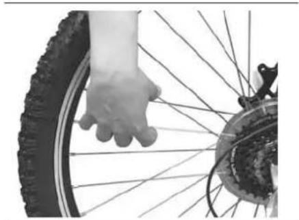
- Squeeze each adjoining pair of spokes on either side of each wheel between your thumb and index finger.
natural_image
Close-up of a hand pressing down on a bicycle wheel (no text or symbols visible)OWNER'S MANUAL·95
All pairs should feel the same, otherwise your specialized bicycle dealer should check the wheels for tension and trueness. Do not ride the bike till then.
- Press the brake levers. The pads must touch the rim within 2cm of brake lever movement. Full braking force must be applied without the brake lever touching the handlebar. If this is not the case, the brakes need adjustment. Do not ride the bike until a qualified bicycle technician adjusts the brakes.
- If your bicycle has a coaster brake make sure that the coaster brake arm is securely fastened on the chain stay. If the arm or its mounting bracket is loose, do not ride the bike unless a qualified bicycle shop properly secures the coaster brake.
- Operate both brakes once or twice. Visually check the brake cables and ensure that brake lever motion is properly transmitted to the brake arms. If not, do not ride the bike until a qualified bicycle technician adjusts the brake cables.
- Check both brake and gear cables and cable housings. If you observe rust, kinks or fraying, have your bicycle dealer replace them.
- Check that the saddle and the handlebar stem are aligned with the top tube tight enough so that you cannot twist them.
- If the handlebar grips are not in a good condition or tight enough, replace them with new ones.
On a bicycle-ride-basis and before you start riding, i.e. hopefully and potentially on a daily basis, please refer to the BICYCLE CHECK chapter on page 44 and perform the simple checks mentioned there; this minimizes the risk of accident and injury.
BICYCLE WARRANTY
For a more efficient service you are kindly requested to fill in IDEAL BICYCLE WARRANTY FORM/CARD on page 67. This warranty covers the replacement of the frame, should a defect in material or workmanship occur. The defect must be verified by a specialized IDEAL bicycle dealer within the warranty period, which starts from the date of original purchase and lasts for:
• Five (5) years for all types of steel frames.
• Five (5) years for alloy hard tail frames.
• Three (3) years for carbon frames.
• Three (3) years for alloy suspension frames.
All other components are guaranteed against faulty workmanship or materials for a period of two (2) years from the date of original purchase.
Claims under this warranty are valid for the original owner only and must be accompanied by dated proof of original purchase. Initially, all claims must be made through the specialized IDEAL bicycle dealer who supplied the bicycle.
The above mentioned warranty periods shall only be granted under the condition that at least once a year a maintenance service has been effected according to maintenance requirements as set forth in this Manual by a specialized IDEAL bicycle dealer.
For this purpose a 5-year maintenance service plan for your IDEAL bicycle can be found in the last part of this Manual, right before the warranty card. The specialized IDEAL bicycle dealer shall confirm the effected annual maintenance service by signature and stamp. In case you keep your IDEAL bicycle for a longer period than five years, please feel free to photocopy and add more unfilled pages to this plan.
Costs for maintenance and service have to be born by the owner of the IDEAL bike. In case of a warranty claim, the decision to repair or to replace the defective part is made by IDEAL upon its sole discretion. Non defective parts will only be replaced at the expense of the bicycle owner.
At the end of this Manual there is a warranty form that needs to be filled in and signed by the customer. A copy of this form must remain with the IDEAL bicycle dealer, upon acceptance and signature of the customer. Showing this form together with the defective part in case of a warranty claim is obligatory, otherwise no warranty is granted.
EXCLUSIONS
Normal wear and tear is not covered by this warranty. Please read the next chapter to learn more about the parts that fall in this category.
The manufacturer of IDEAL bikes shall not be bound to make good any defect where the bicycle and/or its components have been subject to misuse, neglect, accidental damage, abuse, improper assembly and improper maintenance by other than a specialized IDEAL bicycles dealer. The use of parts and/or devices which is not consistent with the use originally intended for the bicycle as sold, as well as damages caused by using non-original parts or parts not approved by a specialized IDEAL bicycles dealer, are not covered by this warranty
This warranty is void if the bicycle is modified from its original condition or the bicycle is used for other than normal activities, including, but not limited to, failing to follow the instructions included in this Owner's Manual, or using the bicycle in competition events, including, but not limited to, bicycle racing, stunt riding, ramp jumping or similar activities.
IDEAL hereby grants a voluntary limited manufacturer's warranty, which is provided under the specific terms and conditions exclusively described in this document. This warranty does not affect any statutory rights of the customer.
WARNING
Like any mechanical device, a bicycle and its components are subject to wear and stress. Different materials and mechanisms wear or fatigue from stress at different rates and have different life cycles. If a component's life cycle is exceeded, it can fail suddenly and catastrophically, causing injury to the rider.
Many bicycle and service tasks require special training, skill, knowledge and tools. Do not begin any adjustments or service on your bicycle, unless you know that you can properly complete them. Improper adjustment or service may result in damage to the bicycle or in an accident which can cause serious injury.
Like all sports, cycling involves risk of injury and damage. By choosing to ride a bicycle, you assume the responsibility for that risk. So you need to know and constantly practice the rules of safe and responsible riding.
ATTENTION
To ensure the safety of riding your bike, it is required that certain parts (such as forks, suspension forks and rear shocks) go through periodical checks and maintenance, according to their manufacturer's guide accompanying each product. For these services please always contact a specialized IDEAL bicycle dealer.
The periodical checking and service of the bicycle according to the instructions of the manufacturer described in this manual are absolutely necessary for a safe and enjoyable riding.
In case that, despite the recommendations and instructions of the manufacturer, the bicycle owner/ user does not perform periodical checking and service of the bicycle, he/ she undertakes the risk of serious accident, for which the manufacturer has no responsibility.
BICYCLE PARTS OF WEAR AND TEAR
Parts of wear and tear are excluded from any warranty.
Normal parts of wear and tear, i.e. parts and components that will wear out by definition because they are being used, include tires, tubes, saddles, brake shoes/pads, brake & gear cables & inner wires, chain, sprockets, chainrings, derailleur pulleys, rims, handlebar grips, reflectors and light systems. The wear out of above parts depends on bicycle maintenance, bicycle care, riding style and riding conditions. The result of these parameters is the time by which above parts will start to function below perfect. It is of paramount importance that those parts are immediately replaced when wear and tear become obvious.
Wear and tear also comes in when your bicycle sustains an impact. In such a case, first of all check yourself for injuries, and take care of them as best you can. Seek medical help if necessary. Next, check your bike for damage. After any crash, take your bike to a specialized bicycle dealer for a thorough check. A crash or other impact can put extraordinary stress
OWNER'S MANUAL·97
on bicycle components, causing them to fatigue prematurely. Components suffering from stress fatigue can fail suddenly and catastrophically, causing loss of control and fall.
Nothing lasts forever, including your IDEAL bicycle. When the useful life of your bike or its components is over, continued use is hazardous. Every bicycle and its component parts have a finite, limited useful life. The length of that life will vary with the construction and materials used in the frame and components; the maintenance and care the frame and components receive over their life; and the type and amount of use to which the frame and components are subjected. Use in competitive events, trick riding, ramp riding, jumping, aggressive riding, riding on severe terrain, riding in severe climates, riding with heavy loads, commercial activities and other types of non-standard use can dramatically shorten the life of the frame and components. Any one or a combination of these conditions may result in an unpredictable failure. All aspects of use being identical, lightweight bicycles and their components will usually have a shorter life than heavier bicycles and their components. In selecting a lightweight bicycle or components you are making a tradeoff, favoring the higher performance that comes with lighter weight over longevity. So, If you choose lightweight, high performance equipment, be sure to have it inspected frequently.
Metals are subject to fatigue. With enough cycles of use, at high enough loads, metals will eventually develop cracks that lead to failure. Fatigue is the term used to describe accumulated damage to a part caused by repeated loading. Fatigue has nothing to do with time or age. A bicycle parked in a garage does not fatigue. Fatigue happens only through use. On a microscopic level, a crack forms in a highly stressed area. As the load is repeatedly applied, the crack grows. At some point the crack becomes visible to the naked eye. Eventually it becomes so large that the part is too weak to carry the load that it could carry without the crack. At that point there can be a complete and immediate failure of the part. A part so strong that its fatigue life is nearly infinite, is possible to be designed and manufactured. But this requires a lot of material and thus weight. Any structure that must be light and strong will have a finite fatigue life. Airplanes, cars, motorcycles they all have parts with finite fatigue lives. If you wanted a bicycle with an infinite fatigue life, it would weigh far more than any bicycle sold today.
A few simple rules about wear, tear, and fatigue follow:
- Once a crack starts, it can grow and it can grow fast. All cracks are potentially dangerous and will only become more dangerous; never less. So if you find crack, replace the part.
- Cracks grow quicker when they are in a corrosive environment. Clean and lubricate your bicycle, protect it from salt and remove any salt as soon as possible. Salt is a slow death for all parts actually; even without cracks, it is very common that salt will get through small surface scratches that have nothing to do with strength & fatigue.
• Stains and discoloration may occur near cracks. So such a staining is a warning sign that a crack exists. Therefore, you must inspect and investigate any staining to see if it is associated with a crack.
- Significant scratches, dents or scoring are starting points for cracks. Such areas facilitate the concentration and amplification of stresses. They must be immediately repaired or the complete part must be replaced.
- Some cracks make a creaking noise while riding. Such noises may thus be a warning signal. A well-maintained bicycle must be quiet and free of creaks and squeaks. Whatever causes noise, must be fixed promptly and permanently.
In most cases a fatigue crack is not a defect. It is a sign that the part has been worn out, a sign the part has reached the end of its useful life. When car tires wear down to the point that the tread bars are contacting the road, those tires are not defective but worn out. When a metal part shows a fatigue crack, it is worn out and the crack says "time for replacement."
Fatigue is not a perfectly predictable science.
Factors that shorten product life:
• Hard, harsh riding style
• "Hits," crashes, jumps, other "shots" to bike
• High mileage
• Higher body weight
• Stronger, more fit, more aggressive rider
• Corrosive environment (wet, salt air, winter road salt, accumulated sweat)
• Presence of abrasive mud, dirt, sand, soil in riding environment
Factors that lengthen product life:
- Smooth, fluid riding style
- No "hits," crashes, jumps to bike
- Low mileage
- Lower body weight
• Less aggressive rider
• Non-corrosive environment (dry, salt-free air)
• Clean riding environment
Do not ride a bicycle or component with any crack, bulge or dent, even a small one. Riding a cracked frame, fork or component could lead to complete failure, with risk of serious injury.
A lot of frames, forks, handlebars, stems, seat posts, bar ends, etc nowadays are made of carbon. Carbon fibers allow the engineers to strengthen structures in pre-determined directions, thus keeping the overall weight very low. Metal structures on the contrary present the same properties in all directions and require bigger dimensions to exhibit the same strength. Carbon fiber components are also much more resistant to corrosion than metals. So carbon parts usually have a better, longer fatigue life than metal ones, provided they are well designed and made of course. But there a couple of big disadvantages. Carbon will not bend, crack or buckle when overloaded. It will simply snap and fail. Carbon is much easier to start a crack from simple contacts and scratches. Delamination is the first indication, i.e. when carbon layers start to 'unfold' and the bonds between successive carbon layers start to break.
RIDER WEIGHT ACCORDING TO EN STANDARDS
The components of IDEAL bicycles fulfill the European standards (safety requirements and bicycle test methods) as follows:
| EUROPEAN STANDARDS | IDEAL BICYCLES | ||
| Standard by category | Total rider and bicycle weight (maximum) | Rider and Load weight (maximum) | Total weight (maximum) |
| EN14765 children bicycles | 30 kg | 30 kg | 40 kg |
| EN14764 city and trekking bicycles | 100 kg | 100 kg | 120 kg |
| EN14766 mountain bicycles (MTB, ATB) | 100 kg | 100 kg | 120 kg |
| EN14781 road racing bicycles | 100 kg | 100 kg | 110 kg |
RECOMMENDED TORQUES
The tables below include the recommended torque values for parts which are assembled on Ideal bicycles (model years 2013). These values ensure safety against application of excessive or inadequate torque during tightening of each bolt.
Make sure that the service section of the specialized bicycle shop you are visiting owns and uses these tables.
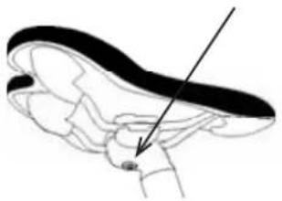
natural_image
Anatomical line drawing of a biological structure with an arrow pointing to a specific region (no text or labels present)| Model Name | Torque for bolts related to hand/bar | Torque for bolts related to steerer | Torque for adjusting bolt |
| RACE PRO TEAM | 5 Nm | 5 Nm | |
| RACE PRO 29 | |||
| TRAXER | |||
| PRISMA | |||
| BODIMMAX | |||
| TARGET | |||
| HILLMASTER | |||
| ZIGZAG | |||
| TRAXER COMP | |||
| KRITTON | |||
| ZIGZAG 29 | |||
| PRO RIDER 29 | |||
| STROKE | |||
| AXION | |||
| VSR PRO | |||
| VSR COMP | |||
| PRO RIDER | |||
| STROBE | |||
| FREEDER | |||
| MOOVIC | 14 Nm | 14 Nm | |
| TRIAL | |||
| INTEGRATOR | 5 Nm | 5 Nm | |
| ERGOMAX | |||
| FUTOUR | |||
| MULTIGO | |||
| OPTIMUS | |||
| MEGISTO | 10 Nm | 9 Nm | 18-25 Nm |
| TESTEK | |||
| UNIGO | |||
| CITY-LIFE | |||
| TRAVELON | |||
| CROSSMO | 8 Nm | 18-25 Nm | |
| NERGETIC | |||
| EZIGO | |||
| INDIGO | 11-12 Nm | 14-15 Nm | |
| CITY LIFE NEXUS 3 | |||
| STAGE TEAM | 5 Nm | 5 Nm | |
| STAGE | |||
| ON ROAD | |||
| INTEMPO | |||
| STREAMLITE | |||
| CHICANE | |||
| CITYRUN | 11-12 Nm | 14-15 Nm | 18-25 Nm |
| V-TRACK | 14-15 Nm | 14-15 Nm | |
| CITYLIFE 20 | |||
| CITYLIFE 24 | |||
| AXION 24 | 14-15 Nm | 14-15 Nm | |
| STROBE 24 | |||
| STROBE 20 | |||
| DSS 20 | 14 Nm | 14 Nm | |
| DSS 24 | |||
| CONDOR 20 | |||
| X-TEN | 18 Nm | 18 Nm | |
| X-SIX |
100 • OWNER'S MANUAL
| SEAT-SEAT POST | |
| Model Name | Torque |
| RACE PRO TEAM | 12 Nm |
| RACE PRO 29 | |
| TRAXER | |
| PRISMA | |
| VSR PRO | |
| INTEGRATOR | |
| STAGE | |
| ON ROAD | |
| TRAXER COMP | 22 Nm |
| BOOMMAX | |
| TARGET | |
| HILLMASTER | |
| ZIGZAG | |
| KRITTON | |
| ZIGZAG 29 | |
| PRO RIDER 29 | |
| VSR COMP | |
| PRO RIDER | |
| STROBE | |
| FREEDER | |
| STROKE | |
| AXION | |
| ERGOMAX | |
| OPTIMUS | |
| MEGISTO | |
| STAGE TEAM | |
| INTEMPO | |
| STREAMLITE | |
| CROSSMO | |
| NERGETIC | |
| CHICANE | |
| CITYRUN | |
| FUTOUR | |
| MULTIGO | |
| EZIGO | |
| INDIGO | |
| TRAVELON | 18-25 Nm |
| TESTEK | 18-20 Nm |
| X-TEN | 36 Nm |
| X-SIX | |
| V-TRACK | |
| UNIGO | 20 Nm |
| TRIAL | |
| MOOVIC | |
| CITYLIFE | |
| CITYLIFE 20 | |
| CITYLIFE 24 | |
| AXION 24 | |
| STROBE 24 | |
| DSS 24 | |
| DSS 20 | |
| STROBE 20 | |
| CONDOR 20 | |
| COBI | |
| SEAT CLAMP | |
| Model Name | Torque |
| RACE PRO TEAM | N/A |
| RACE PRO 29 | |
| TRAXER | |
| PRISMA | |
| VSR PRO | |
| INTEGRATOR | |
| TRAXER COMP | |
| BOOMMAX | |
| TARGET | |
| HILLMASTER | |
| ZIGZAG | |
| KRITTON | |
| ZIGZAG 29 | |
| PRO RIDER 29 | |
| VSR COMP | |
| PRO RIDER | |
| STROBE | |
| FREEDER | |
| TRIAL | |
| STROKE | |
| AXION | |
| ERGOMAX | |
| OPTIMUS | |
| MEGISTO | |
| CITYLIFE | |
| CROSSMO | |
| NERGETIC | |
| MOOVIC | |
| CHICANE | |
| CITYRUN | |
| FUTOUR | |
| MULTIGO | |
| EZIGO | |
| INDIGO | |
| TRAVELON | |
| TESTEK | |
| AXION 24 | |
| STROBE 24 | |
| DSS 24 | |
| DSS 20 | |
| STROBE 20 | |
| CONDOR 20 | |
| COBI | |
| STAGE | 5 Nm |
| STAGE TEAM | |
| INTEMPO | |
| ON ROAD | |
| STREAMLITE | |
| X-TEN | 8-9 Nm |
| X-SIX | |
| V-TRACK | 9-10 Nm |
| UNIGO | |
| CITYLIFE 20 | |
| CITYLIFE 24 | |
HS170N3
OWNER'S MANUAL·101
| PEDAL | |
| Model Name | Torque |
| RACE PRO TEAM | 50 Nm |
| RACE PRO 29 | |
| TRAXER | |
| TRAXER COMP | |
| BOOMMAX | |
| TARGET | |
| HILLMASTER | |
| ZIGZAG | |
| PRISMA | |
| KRITTON | |
| ZIGZAG 29 | |
| PRO RIDER 29 | |
| VSR PRO | |
| VSR COMP | |
| PRO RIDER | |
| STROBE | |
| FREEDER | |
| TRIAL | |
| STROKE | |
| AXION | |
| INTEGRATOR | |
| ERGOMAX | |
| OPTIMUS | |
| MEGISTO | |
| FUTOUR | |
| MULTIGO | |
| TRAVELON | |
| EZIGO | |
| INDIGO | |
| TESTEK | |
| CITYLIFE | |
| UNIGO | |
| CROSSMO | |
| NERGETIC | |
| MOOVIC | |
| CHICANE | |
| CITYRUN | |
| V-TRACK | |
| CITYLIFE 20 | |
| CITYLIFE 24 | |
| AXION 24 | |
| STROBE 24 | |
| DSS 24 | |
| DSS 20 | |
| STROBE 20 | |
| CONDOR 20 | |
| X-TEN | |
| X-SIX | |
| HUB | |
| Model Name | Torque |
| CITY LIFE (w/ hub dynamo) | 30-45Nm |
| STROBE ATB | |
| FREEDER ATB | |
| CROSSMO STREET 700C | |
| TESTEK | |
| EZIGO | |
| TRAVELON | |
| MULTIGO | |
| STROBE 20 ATB | |
| STROBE 24 ATB | |
| V-TRACK | 30Nm |
| CITY LIFE (w/o hub dynamo) | |
| CITY LIFE 24° | |
| MOOVIC | |
| TRIAL | |
| FREEHUB | |
| Model Name | Torque |
| CITY LIFE 700C | 30Nm |
| V-TRACK | |
| STROBE 20" ATB | |
| STROBE 20" | |
| STROBE 24" | |
| STROBE 24" MD | |
| STROBE 24" ATB | |
| UNIGO | |
| TRIAL | |
| MOOVIC | |
| CITY LIFE NEXUS 7 | 30-45Nm |
| CITY LIFE NEXUS 3 | |
| STROBE 24" NEXUS | |
| STROBE 20" NEXUS | |
| EZIGO NEXUS 7 | |
| EZIGO NEXUS 3 | |
| TRAVELON NEXUS 8 | |
Model:
Date of purchase:
Frame material:
Frame color:
Frame size:
IDEAL dealer must check appropriate bullet points:
O Frame
O Rigid or suspension fork
O Rear shock
O Brakes, as per enclosed manufacturer's instructions Manual
O Brake shoes / pads, brake levers, brake cables & inner wires
O Shifters, front & rear derailleur, shifting cables
O Chain, chainwheel, freewheel / cassette sprocket, bottom bracket
O Pedals
O Handlebar, stem, grips and head set
O Complete wheels, stability, truing & rim surface / limit line
O Hubs, spokes, nipples, rim area around nipples
O Air pressure of the tire tubes and overall condition of the tire sidewalls and treads
O Complete lighting system
O Bell
O All screws, nuts & bolts, cable guides & bosses
Dealer comments:
Date of service:
Dealer signature:
Dealer stamp:
Model:
Date of purchase:
Frame material:
Frame color:
Frame size:
IDEAL dealer must check appropriate bullet points:
O Frame
O Rigid or suspension fork
O Rear shock
O Brakes, as per enclosed manufacturer's instructions Manual
O Brake shoes / pads, brake levers, brake cables & inner wires
O Shifters, front Ⓡ rear derailleur, shifting cables
O Chain, chainwheel, freewheel / cassette sprocket, bottom bracket
O Pedals
O Handlebar, stem, grips and head set
O Complete wheels, stability, truing & rim surface / limit line
O Hubs, spokes, nipples, rim area around nipples
O Air pressure of the tire tubes and overall condition of the tire sidewalls and treads
O Complete lighting system
O Bell
O All screws, nuts & bolts, cable guides & bosses
Dealer comments:
Date of service:
Dealer signature:
Dealer stamp:
Model:
Date of purchase:
Frame material:
Frame color:
Frame size:
IDEAL dealer must check appropriate bullet points:
O Frame
O Rigid or suspension fork
O Rear shock
O Brakes, as per enclosed manufacturer's instructions Manual
O Brake shoes / pads, brake levers, brake cables & inner wires
O Shifters, front Ⓡ rear derailleur, shifting cables
O Chain, chainwheel, freewheel / cassette sprocket, bottom bracket
O Pedals
O Handlebar, stem, grips and head set
O Complete wheels, stability, truing & rim surface / limit line
O Hubs, spokes, nipples, rim area around nipples
O Air pressure of the tire tubes and overall condition of the tire sidewalls and treads
O Complete lighting system
O Bell
O All screws, nuts & bolts, cable guides & bosses
Dealer comments:
Date of service:
Dealer signature:
Dealer stamp:
Model:
Date of purchase:
Frame material:
Frame color:
Frame size:
IDEAL dealer must check appropriate bullet points:
O Frame
O Rigid or suspension fork
O Rear shock
O Brakes, as per enclosed manufacturer's instructions Manual
O Brake shoes / pads, brake levers, brake cables & inner wires
O Shifters, front Ⓡ rear derailleur, shifting cables
O Chain, chainwheel, freewheel / cassette sprocket, bottom bracket
O Pedals
O Handlebar, stem, grips and head set
O Complete wheels, stability, truing & rim surface / limit line
O Hubs, spokes, nipples, rim area around nipples
O Air pressure of the tire tubes and overall condition of the tire sidewalls and treads
O Complete lighting system
O Bell
O All screws, nuts & bolts, cable guides & bosses
Dealer comments:
Date of service:
Dealer signature:
Dealer stamp:
IDEAL BICYCLE WARRANTY FORM/CARD
(If you will not keep this Manual, please tear & keep this page)
IDEAL dealer
Name ____
Address ____
Phone / fax / email / website ____
Customer
Name ____
Address
Phone / fax / email / website ____
IDEAL bicycle
Model
Date of purchase / delivery
Frame material / color / size ____
Frame serial number ____
Declaration of proper handing over
• The above IDEAL bicycle was checked in detail by me.
• The delivery was made properly.
- The Owner's Manual was handed over to me and I received proper oral information about its content.
• I am aware that this warranty is limited to faulty products and that there is no warranty for damages of wear and tear caused by use of this bicycle or damages caused by accidents.
- I am aware that this warranty is granted under the specific terms and conditions exclusively described in this Owner's Manual.
Place / Date
Dealer Stamp
Customer Signature
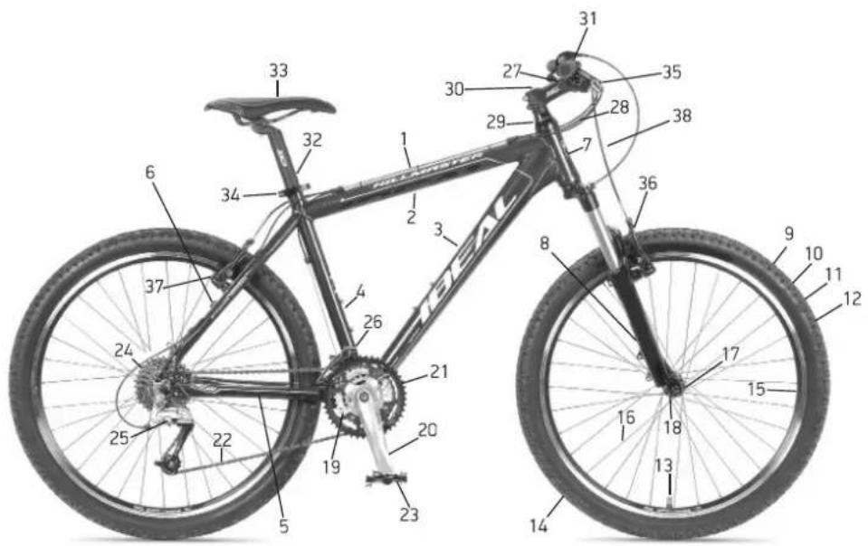
| 1 | frame |
| 2 | top tube |
| 3 | down tube |
| 4 | seat tube |
| 5 | chain stay |
| 6 | seat stay |
| 7 | head tube |
| 8 | fork |
| 9 | wheel |
| 10 | tire |
| 11 | tread |
| 12 | sidewall |
| 13 | valve stem |
| 14 | tube |
| 15 | rim |
| 16 | spokes |
| 17 | hub |
| 18 | quick release |
| 19 | bottom bracket |
| 20 | crank |
| 21 | chainrings |
| 22 | chain |
| 23 | pedal |
| 24 | freewheel/rear cluster/cassette |
| 25 | rear derailleur |
| 26 | front derailleur |
| 27 | shifter |
| 28 | shifter cable |
| 29 | headset |
| 30 | stem |
| 31 | handlebar |
| 32 | seatpost |
| 33 | saddle |
| 34 | seatpost clamp |
| 35 | brake lever |
| 36 | brake |
| 37 | brake pad |
| 38 | brake cable |
| 39 | disc brake caliper |
| 40 | disc brake rotor |
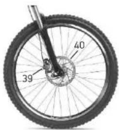
108·OWNER'S MANUAL
DEALER COPY
IDEAL BICYCLE WARRANTY FORM/CARD
(If you will not keep this Manual, please tear & keep this page)
IDEAL dealer
Name ____
Address ____
Phone / fax / email / website ____
Customer
Name ____
Address
Phone / fax / email / website
IDEAL bicycle
Model
Date of purchase / delivery
Frame material / color / size ____
Frame serial number
Declaration of proper handing over
• The above IDEAL bicycle was checked in detail by me.
• The delivery was made properly.
- The Owner's Manual was handed over to me and I received proper oral information about its content.
- I am aware that this warranty is limited to faulty products and that there is no warranty for damages of wear and tear caused by use of this bicycle or damages caused by accidents.
- I am aware that this warranty is granted under the specific terms and conditions exclusively described in this Owner's Manual.
Place / Date
Dealer Stamp
Customer Signature
NOTES
- BICYCLE SAFETY
- MECHANICAL SAFETY
- BICYCLE FIT
- BICYCLE CHECK
- BICYCLE TECH
- Wheels
- Removing a Quick Release Front Wheel
- Installing a Quick Release Front Wheel
- Removing a Quick Release Rear Wheel Shift the rear derailleur to the smallest, outer rear sprocket; this is the high gear position.
- Removing a Bolt-On Front Wheel
- Installing a Bolt-On Front Wheel
- Removing a Bolt-On Rear Wheel
- Installing a Rear Bolt-On Wheel
- Seat Post Quick Release
- Brakes
- Brake Controls
- Brakes Operation
- Brakes Tech
- Brakes & Rims
- Transmission Tech
- Transmission Fit
- Pedals
- Bicycle Suspension
- Tires & Tubes
- BICYCLE SERVICE
- BICYCLE CARE
- BICYCLE MAINTENANCE, CHECK & SERVICE
- BICYCLE WARRANTY
- EXCLUSIONS
- WARNING
- ATTENTION
- BICYCLE PARTS OF WEAR AND TEAR
- RIDER WEIGHT ACCORDING TO EN STANDARDS
- RECOMMENDED TORQUES
- IDEAL BICYCLE WARRANTY FORM/CARD
- IDEAL dealer
- Customer
- IDEAL bicycle
- Declaration of proper handing over
Brand : IDEAL
Model : VSR Pro
Category : Bicycle