
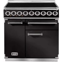
211 EEO Ceramic - Cooker FALCON - Free user manual and instructions
Find the device manual for free 211 EEO Ceramic FALCON in PDF.


| Product Type | Freestanding Electric Cooker |
| Brand | Falcon |
| Model | 211 EEO Ceramic |
| Hob Type | Ceramic |
| Number of Cooking Zones | 4 |
| Oven Type | Electric |
| Oven Capacity | 59 liters |
| Overall Dimensions (H x W x D) | 90 cm x 50 cm x 60 cm |
| Weight | 48 kg |
| Power Supply | 220-240 V, 50 Hz |
| Total Power Consumption | 9.5 kW |
| Oven Functions | Conventional heat, grill, fan-assisted |
| Hob Controls | Knobs |
| Oven Timer | Yes, mechanical |
| Ceramic Hob Cleaning | Use a ceramic hob scraper and cleaner |
| Oven Cleaning | Manual cleaning with mild detergent |
| Child Lock | Yes, on oven door |
| Automatic Shut-Off | Yes, for hob zones |
| Spare Parts Availability | Available from authorized dealers |
| Reparability | Repairable by qualified technician |
| Warranty | 2 years |
| Energy Efficiency Class | A |
Frequently Asked Questions - 211 EEO Ceramic FALCON
User questions about 211 EEO Ceramic FALCON
0 question about this device. Answer the ones you know or ask your own.
Ask a new question about this device
Download the instructions for your Cooker in PDF format for free! Find your manual 211 EEO Ceramic - FALCON and take your electronic device back in hand. On this page are published all the documents necessary for the use of your device. 211 EEO Ceramic by FALCON.
USER MANUAL 211 EEO Ceramic FALCON
& Installation and Servicing Instructions
U1 353 01
Contents
211 GEO Dual Fuel Range 4
Control Panel Layout 4
General Information 5
Warranty & Service 5
Be safe 5
The Hob 6
Oven Operation 8
Oven Fitments 8
Left Hand Oven Cooking Chart 10
Right Hand Fan Oven Cooking Chart 12
Grill Operation 14
The Ambient Drawer 15
Cleaning 16
Troubleshooting 18
General Safety Instructions 20
Optional Extras 22
Splashback Fitting Instructions 22
Utensil Rack Fitting Instillation 22
Flue Spacer Fitting Instructions 23
Installation and Servicing Instructions 24
SECTION 1 - INSTALLATION 24
SECTION 2 - ASSEMBLY and COMMISSIONING 26
SECTION 3 - SERVICING 26
Circuit Diagram Top 30
Circuit Diagram Bottom 31
211 GEO Dual Fuel Range
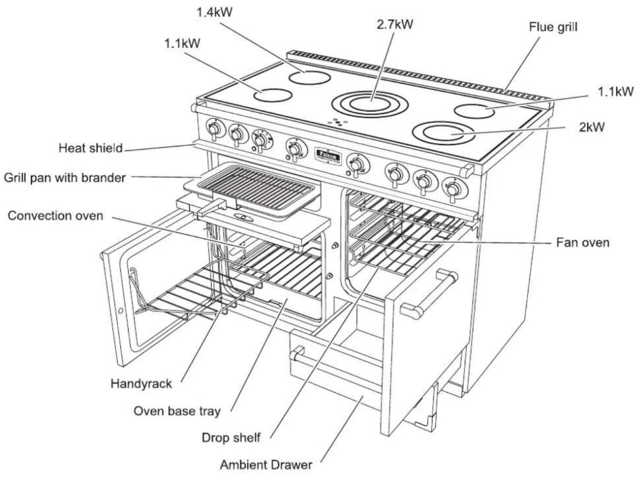
Control Panel Layout

General
Information
These units have been CE-marked on the basis of compliance with the EMC and Low Voltage Directive for the Countries stated on the Data Plate.
The Range must be installed by a competent person, in compliance with the Installation and Servicing Instructions and National Regulations in force at the time. In the UK, particular attention should be paid to the following: -
I.E.E Regulations for Electrical Installations
Health and Safety at Work Act
The User must not adjust parts that have been protected by the manufacturer. Regular servicing by a competent person must be carried out to ensure the continued safe and efficient performance of the appliance.
Warning - THIS APPLIANCE MUST BE EARTHED!
The installer should instruct the User with regard to correct operation and maintenance of the unit before handing over this manual.
Some parts will, by necessity, become very hot and will cause burns if touched accidentally.
CUSTOMER CARE
This cooker has been manufactured in accordance with the safety aspects that European Standards demand.
Please keep this manual close at hand and available to anyone who may use the Range.
By following all the recommendations made in these instructions you will be able to make best possible use of your cooker.
The installer will ensure that the unit is correctly fitted and adjusted. Safe and efficient use requires that it be serviced regularly. Frequency of service is dependent upon usage.
Only competent persons should be allowed to make adjustments. Replacement parts are available from your supplier not direct from Falcon. When ordering, please quote the Serial Number, which can be found on the data plate located externally at the rear of the unit.
We would advise that extra care be taken when using and cleaning the unit.
YOUNG CHILDREN SHOULD NOT BE ALLOWED NEAR THE APPLIANCE.
Cooking produces heat and moisture. Ensure the room is well ventilated. If mechanical extraction is required we recommend the installation of a Falcon Extraction Hood.
Note
The unit will emit a slight odour when used for the first time; this will quickly disappear.
Warranty & Service
For details of the Falcon Warranty and Service arrangements please see the separate 'Customer Care' leaflet.
Be safe
We recommend you read pages 20 - 21 if you have not used an ceramic electric cooker before. We describe some basic guidelines on how to use a cooker safely.
The Hob
When you cook on a ceramic hob its very important to use the right sort of pans...
natural_image
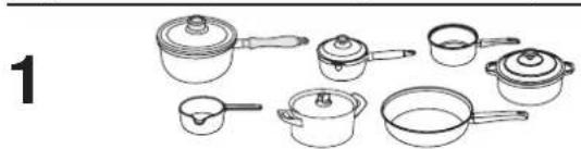
Line drawing of various cooking pots and containers arranged in a row (no text or symbols)Use only pans that are suitable for ceramic hobs.
We recommend stainless steel and enamelled steel pans because pots and pans with copper or aluminium bases leave traces on the hob that are difficult to remove.
Glass-ceramic cookware is not suitable because of its poor conductivity.

Pots and pans should have thick, smooth, flat bottoms. This ensures that there is the maximum heat transfer from the hob to the pan, making cooking quick and energy efficient.
Never use a round bottomed Wok even with a stand.
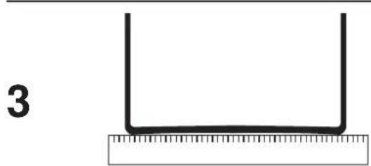
The very best pans have bases that are very slightly curved in when cold. If you hold a ruler across the bottom you will see a small gap in the middle. When they heat up the metal expands and lies flat on the cooking surface.
Make sure that the base of the pan is clean and dry to prevent any residue burning onto the hob panel. This also helps prevent scratches and deposits (such as lime specks).
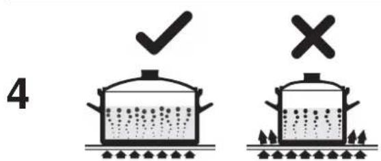
Always use pans that are the same size as (or slightly larger than) the areas marked on the hob top. Using smaller pans wastes heat, and any spillage will be burnt on. Using a lid will help the contents boil more quickly.
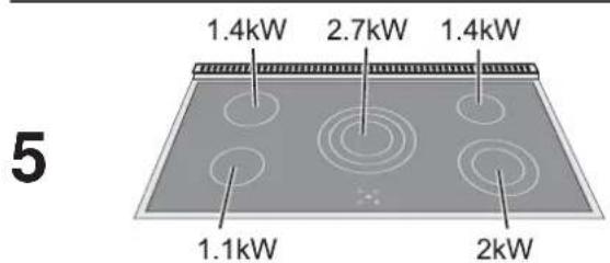
These are the various hob areas
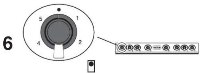
The drawing by each knob indicates which area that knob controls. This one is the left hand rear control.
The setting you need depends on the kind of pan you use and the quantity of food. Higher settings are required for larger quantities of food.

natural_image
Illustration of a cooking pot on a stove with circular patterns (no text or symbols)The areas marked with concentric circles have more than one element.
The centre hob area has 3 elements.

To operate the inner element only, turn the knob clockwise to Settings 1 - 5
(1: lowest / 5: highest).
To use the middle and inner elements, turn the knob to ● before turning anti-clockwise to the setting you need.


To operate ALL the elements, turn the knob
to before turning anti-clockwise to the setting you want.
To return to a previous element combination, turn knob to OFF position and start again.
The right hand front hob area has two elements.

Turn the control knob clockwise to heat the whole area for larger pans - turn it the other way to just heat the inner part for smaller pans.
8
natural_image
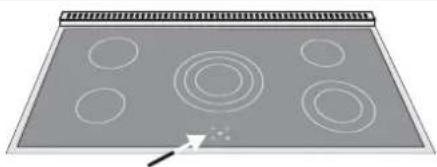
Diagram of a rectangular tray with six circular holes and concentric rings, no text or symbols present.There are indicator lights for each of the cooking areas. These come on when a hob control is turned on and stay lit while the surface cools. Always take care before touching the surface even when it is turned off - it may be hotter than you think.
WARNING
EVEN WHEN INDICATORS GO OUT, THE SURFACE MAY NOT HAVE COOLED COMPLETELY.
9
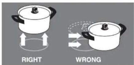
Always lift pans off the hob. Sliding pans may cause marks and scratches. Always turn the control to the off position before removing a pan.
10

natural_image
Illustration of a car with motion lines and circular patterns on a gray background (no text or symbols)Although the ceramic surface is very strong, a heavy or sharp falling object (a salt cellar for example) might cause the surface to crack. If you find a crack in the surface immediately disconnect the appliance from the supply and arrange for its repair.
Care should be taken that no water seeps into the appliance.
11

natural_image
Simple illustration of a fried egg with a cross symbol (no text or labels)Never cook directly on the surface.
The kind of pan you use and the quantity of food affects the setting required. Higher settings are required for larger quantities of food.
Naturally, the surface must be washed after use in order to prevent it from becoming scratched or dirty.
When cooking on the hob you may see the hob area you are using switch off and on. This is caused by a safety device that limits the temperature of the hob. It is quite normal, especially when cooking at high temperatures. If it happens a lot with a particular pan however it may mean the pan is not suitable – perhaps too small or too uneven - for a ceramic hob.
Sugar spillage will permanently damage the hob and therefore must be cleaned off with care immediately. Never let sugar spillage cool before trying to remove it.
If sugar or foods with high sugar content, aluminium foil or plastic items are accidentally allowed to melt on the hob surface remove them immediately from the hot cooking area using a scraper to avoid any possible damage to the surface. See 'Cleaning your cooker'.
Never cut directly on the cooking surface.
Don't cook directly on the hob surface i.e. without a pan or utensil
Don't use the hob as a work surface
Don't drag or slide utensils across the hob surface
Don't place anything between the base of the pan and the hob surface (i.e. asbestos mats, aluminium foil, Wok stand)
Don't leave utensils, foodstuffs or combustible items on the hob when it is not in use. (e.g. tea towels, frying pans containing oil)
Don't place plastic or aluminium foil, or plastic containers on the hob
Don't leave the hob zones switched on unless being used for cooking
Don't place large preserving pans or fish kettles across two heating zones
Don't place utensils partly covering a heating zone. Always place utensils centrally.
Never allow anyone to climb or stand on the hob.
Oven Operation
During use the appliance becomes hot. Care should be taken to avoid the touching heating elements inside the ovens.

The Ovens
This model includes two types of oven. Before using either for the first time, heat to 200°C for 30 minutes to dispel manufacturing odours.
Right Hand Oven - Fan Assisted
The fan draws air from the oven to be heated by the element. The hot air is then forced around the cavity via the top and bottom of the rear panel and circulates this continuously around the food resulting in quicker heat transfer.
Left Hand Oven - Conventional Oven
This oven is fitted with two elements. The top which is visible and the other located below the bottom panel. The Browning Feature is provided by the top element and can be used at the end of any normal cooking cycle to achieve an extra browning effect on au-gratin dishes or as a meat crisper.
Both oven controls are clearly marked on the facia.
To Operate either Oven
a) Check the electricity supply is switched on.
b) Turn the oven knob clockwise to the desired temperature.

c) The neon indicator light will come on until pre-set temperature is reached.
d) The neon will cycle on and off to indicate that the oven temperature is being maintained.
Note
Cooking times may vary from those of your previous unit and temperatures may also require to be increased when other sections of the range are in use.
Using The Browning Element
When the cooking cycle is over, turn the left hand oven thermostat knob to the Browning Position indicated on the facia.
Important Note
The upper and lower elements will switch off automatically and operate the browning element only.
Oven Fitments

Oven Roof (Right Hand Oven only)
Ensure that removable roof is in correct position, pushed firmly to oven cavity rear.
Shelves
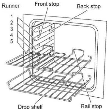
Two shelves are provided with each oven. A drop shelf is also supplied.
The shelves may be used in any of the five positions and should always be pushed firmly to the oven rear.
To remove a shelf, pull forward to the stop position and tilt upward.
Replace in reverse order.
When preparing more than one item per shelf, always leave a fingers width between them so that the air can circulate.
Do not push a dish (or dishes) too far back on shelf as over-browning may occur.
To Fit the Handyrack (Left Hand Oven only)
The Handyrack should only be used with the supplied meat tin, which is designed to fit the Handyrack. Any other vessel could be unstable.

To fit the Handyrack, locate one side of it on the door bracket.

Then spring the other side out to clip it onto the other bracket.

natural_image
Line drawing of a hand holding a tool or bracket (no text or symbols)Note
The Handyrack is designed for use in left hand OVEN ONLY.
The Handyrack can be used instead of a shelf. There are two fitting two positions on the door.
Remove a shelf and locate the other to avoid Handyrack. The shelf must always be located before positioning
Handyrack. Failure to comply with this instruction may damage your appliance.
The maximum weight that can be held by the rack is 5.5kg.
When rack is used in the highest position, other dishes may be cooked on the fifth position. When used in lowest position, another dish may be prepared on the second shelf position.
Roasting Tin with Integral Trivet
The roasting tin will hold an oven ready joint or fowl up to a weight of 5.5kg. The trivet reduces fat splash during open roasting.
To Reduce Fat Splash
Dry meat and vegetables thoroughly before loading oven. Potatoes or other vegetables that require to be roasted around the joint should first be brushed with oil or melted fat before positioning. Use a smaller tin for roasting lesser joints or small amounts of vegetables. Do not use aluminium foil to cover shelves, linings or oven roof.
Foil should only ever be used to cover food. It is important to avoid blocking the oven vent.
Baking Trays
For even browning, the recommended size of tray is 320mm x 305mm. Two such trays are supplied with the unit.
Up to 16 small cakes, biscuits, scones etc. may be prepared per tray.
The tray front trim should be placed level with shelf front edge.
For extra base browning of pastry dishes, pre-heat a tray for 15 minutes before placing dish in tray centre. If small dishes (i.e. less than 140mm diameter) are used, these should be placed on a baking tray.
In circumstances where spillage or boiling over may occur during the cooking process, always place the dish on a suitable baking tray.
Cooking Hints
Cooking high moisture content foods can create a 'steam burst', when the oven door is opened. When opening the oven stand well back and allow any steam to disperse.

natural_image
Illustration of a hand opening a door with a tray and handle (no text or symbols)When the oven is on, don't leave the door open for longer than necessary, otherwise the knobs may get very hot.
The following operations may be performed in either or both ovens:-
- Baking • Roasting • Pot Roasting • Braising
The right hand oven is fan-assisted with six shelf positions and three shelves supplied. The result of even distribution of heat within the cavity means that temperatures and times will be less than those of a natural convection oven.
The left hand oven has five shelf positions. A standard shelf, drop shelf and Handyrack are supplied. This oven relies upon natural convection (zonal heat) for cooking.
The control has been calibrated to achieve a desired setting as a measurement of the centre temperature (Shelf 3). If the oven is found to be hotter or cooler than the specified mark, the thermostat may require to be replaced.
With regard to the left hand oven, the heat will rise regardless of the centre temperature and the cavity top will always be hotter than the lower area.
This situation can be advantageous, i.e.
Shelf I Browning Meringues, Crispy Bacon.
Shelves 2 & 4 Baked items (Scones, etc.)
Shelf 3 Ribs of Beef
When using the left hand oven, it is important to note that because of the heat variation, the food shelf positions require to be changed during the cooking cycle. This is particularly applicable to baked items such as scones, biscuits, etc. Shelf Positions 2 and 4 should be utilised in such instance.
With regard to the cooking charts - in the case of single tray cooking, it is recommended that Positions 2 or 3 be utilised. In the case of two shelf cooking, Positions 2 and 4 should be used. This is also relevant if the digits 2, 3 and 4 appear in the shelf column.
USING A PROBE
A hand held thermometer is an asset to any kitchen and is particularly useful in the preparation of meat, fish and dishes such as paté. A probe is recommended for checking that a joint or piece of poultry is sufficiently cooked by inserting the probe through the thickest part of the meat.
When using a probe it is important to seek the centre of the foodstuff being prepared.
Left Hand Oven Cooking Chart
MEAT and MEAT PRODUCTS Cooking Method °C Shelves Time (mins)
| Topside of Beef (3.6kg) Braised 160 2, 3, 4 (5) 165 | ||||
| Beef Steaks (142g Rump) Braised 190 2, 3, 4 110 | ||||
| Forerib of Beef (3.6kg) | Roast | 190 | 4 (5) | 140 |
| Fillet of Beef (2.3kg) | Roast | 220 | 2, 3, 4 | 85 |
| Leg of Lamb (2.3kg) | Roast | 200 | 2, 3, 4 (5) | 120 |
| Loin of Lamb (1.4kg) | Roast | 220 | 2, 3, 4 | 60 |
| Shoulder of Lamb (2.3kg) | Pot Roast | 200 2, 3, 4 125 | ||
| Leg of Pork (4.1kg) | Roast | 190 | 2, 3, 4 (5) | 170 |
| Loin of Pork (2.3kg) | Roast | 220 | 2, 3, 4 | 110 |
| Gammon (4.1kg) | Bake | 180 | 4 (5) | 170 |
| Savoury Meatballs | Braised | 200 | 2, 3, 4 | 70 |
| Cottage Pie | Bake | 200 2, 3, 4 | 40 | |
| Steak Pie | Bake | 220 2, 3, 4 | 30 | |
| Moussaka | Bake | 200 2, 3, 4 | 35 | |
| Lamb Hot Pot | Bake | 200 | 2, 3, 4 | 50 |
| Lasagne Bolognaise | Bake | 220 2, 3, 4 | 65 | |
| Beef Olives | Braised 180 2, 3, 4 120 | |||
| POULTRY | Cooking Method °C Shelves Time (mins) | ||
| Whole Chicken (1.6kg) | Roast | 200 2, 3, 4 (5) | 80 |
| Chicken Legs | Roast | 200 2, 3, 4 | 35 |
| Chicken Supremes | Baked | 220 2, 3, 4 | 25 |
| Chicken Drumsticks | Roast | 200 2, 3, 4 | 25 |
| Whole Duck (2.3kg) | Roast | 190 2, 3, 4 (5) | 110 |
| Duck Breast | Roast | 190 2, 3, 4 | 35 |
| Whole Turkey (8.2kg) | Roast | 150 5 | 240 |
| Chicken Casserole | Braised 200 2, 3, 4 | 80 | |
| FISH | Cooking Method °C Shelves Time (mins) | |||
| Haddock Fillets (Crumbed) | Baked | 220 2, 3, 4 9 | ||
| Cod Fillets (Crumbed) | Baked | 220 | 2, 3, 4 | 10 |
| Whole Mackerel | Baked | 200 | 2, 3, 4 | 11 |
| Rainbow Trout | Baked | 220 2, 3, 4 | 11 | |
| Herring Fillets (Oatmeal) | Baked | 220 2, 3, 4 9 | ||
| Salmon Steaks | Baked | 200 2, 3, 4 | 12 | |
| Fish Pie (Potato Topped) | Baked | 200 | 2, 3, 4 | 15 |
| Salmon En Croute (Individual) | Baked | 200 | 2, 3, 4 | 30 |
| Fish Cakes (Individual) | Baked | 220 | 2, 3, 4 | 20 |
| FARINACEOUS | Cooking Method °C Shelves Time (mins) | |||
| Rice Pilaff | Braised 220 2, 3, 4 | 20 | ||
| Vegetarian Lasagne | Baked | 200 2, 3, 4 | 55 | |
| Macaroni Au Gratin | Baked | 200 | 2, 3, 4 | 40 |
| POTATOES | Cooking Method °C Shelves Time (mins) | |||
| Roast Potatoes | Roast | 220 | 2, 3, 4 | 30 |
| Fondant Potatoes | Braised 220 2, 3, 4 | 35 | ||
| Dauphinoise Potatoes | Baked | 200 | 2, 3, 4 | 30 |
| Jacket Potatoes | Baked | 200 | 2, 3, 4 | 55 |
| Boulangere Potatoes | Baked | 220 | 2, 3, 4 | 30 |
| Bretonne Potatoes | Baked | 200 | 2, 3, 4 | 40 |
VEGETABLES Cooking Method °C Shelves Time (mins)
| Red Cabbage Braised 200 2, 3, 4 60 | |
| Parsnips Roast 220 2, 3, 4 30 | |
| Stuffed Whole Tomatoes Baked 200 2, 3, 4 12 | |
| Celery | Braised 200 2, 3, 4 60 |
| Stuffed Marrow | Baked 190 2, 3, 4 45 |
| Whole Onions | Roast 220 2, 3, 4 50 |
| Whole Lettuce | Braised 190 2, 3, 4 40 |
| Whole Leeks | Braised 200 2, 3, 4 25 |
| Fennel | Braised 200 2, 3, 4 45 |
| Stuffed Peppers | Baked 220 2, 3, 4 40 |
| MISCELLANEOUS | Cooking Method °C Shelves Time (mins) | |||
| Pizza | Baked 220 2, 3, 4 15 | |||
| Quiche Lorraine | Baked 190 2, 3, 4 30 | |||
| Pastry Shells (Blind) | Baked | 190 | 2, 3, 4 | 10 |
| Yorkshire Pudding (Individual) | Baked 230 2, 3, 4 25 | |||
| Toad In The Hale | Baked 230 2, 3, 4 30 | |||
| BAKERY GOODS | Cooking Method | °C | Shelves | Time (mins) |
| Soda Bread | Baked 220 2, 3, 4 35 | |||
| French Breed | Baked 220 2, 3, 4 25 | |||
| Loaf Bread | Baked 220 2, 3, 4 30 | |||
| Dinner Rolls | Baked 220 2, 3, 4 20 | |||
| Chelsea Buns | Baked 220 2, 3, 4 20 | |||
| Vol-au-vent Cases | Baked 220 2, 3, 4 15 | |||
| Sausage Rails | Baked 220 2, 3, 4 18 | |||
| Croissants | Baked 220 2, 3, 4 20 | |||
| Sultana Scones | Baked 230 | 2, 3,4 | 10 | |
| Meringue Shells | Baked | 90 | 2, 3, 4 | 190 |
| Muffins | Baked 220 2, 3, 4 30 | |||
| Shrewsbury Biscuits | Baked 160 2, 3, 4 25 | |||
| Gingerbread Round | Baked 180 2, 3, 4 35 | |||
| Viennese Rosettes | Baked 160 | 2, 3,4 | 25 | |
| Apple Turnovers | Baked 220 2, 3, 4 30 | |||
| Chocolate Sponge | Baked 180 2, 3, 4 25 | |||
| Victoria Sponge | Baked 180 2, 3, 4 25 | |||
| Banana Loaf | Baked 180 | 2, 3,4 | 50 | |
| Mincemeat Pies | Baked 220 2, 3, 4 20 | |||
| Fruit Slice | Baked 190 2, 3, 4 35 | |||
| Profiteroles | Baked 220 2, 3, 4 22 | |||
| Rich Fruit Cake | Baked | 150 | 4 | 150 |
| Cherry Cake | Baked 160 2, 3, 4 60 | |||
| Shortbread | Baked 160 2, 3, 4 30 |
| SWEETS and DESSERTS | Cooking Method °C | Shelves Time (mins) |
| Eves Pudding | Baked 200 2, 3, 4 50 | |
| Bread and Butter Pudding | Baked 180 2, 3, 4 45 | |
| Apple Tart | Baked 200 2, 3, 4 35 | |
| Bakewell Tart | Baked 190 2, 3, 4 35 | |
| Queen of Puddings | Baked 200 2, 3, 4 20 | |
| Rice Pudding | Baked 180 2, 3, 4 90 | |
| Rhubarb Crumble | Baked 190 2, 3, 4 30 | |
| Stuffed Apples | Baked 200 2, 3, 4 20 | |
| Pavlova | Baked 110 3 & 5 145 | |
| Creme Caramel | Baked 160 2, 3, 4 30 | |
| Jam Roll | Baked 190 2, 3, 4 35 |
Right Hand Fan Oven Cooking Chart
MEAT and MEAT PRODUCTS Cooking Method °C Shelves Time (mins)
| Topside of Beef (2.3kg) Braised 150 3, 6 150 | |||
| Beef Steaks (142g Rump) Braised 180 2, 4, 6 100 | |||
| Forerib of Beef (3.6kg) Roast 180 3, 6 125 | |||
| Fillet of Beef (2.3kg) | Roast 210 2, 4, 6 | 75 | |
| Leg of Lamb (2.3kg) | Roast 180 2, 4, 6 110 | ||
| Loin of Lamb (1.4kg) | Roast 200 2, 4, 6 | 50 | |
| Shoulder of Lamb (2.3kg) | Pot Roast | 190 2, 4, 6 115 | |
| Leg of Pork (4.1kg) | Roast 180 3, 6 160 | ||
| Loin of Pork (2.3kg) | Roast 200 2, 4, 6 100 | ||
| Gammon (4.1kg) | Bake | 170 | 3,6 |
| Savoury Meatballs | Braised | 190 | 2, 4, 6 |
| Cottage Pie | Bake | 190 | 2, 4, 6 |
| Steak Pie | Bake | 200 2, 4, 6 | 30 |
| Moussaka | Bake | 190 2, 4, 6 | 30 |
| Lamb Hot Pot | Bake | 190 | 2, 4, 6 |
| Lasagne Bolognaise | Bake | 200 2, 4, 6 | 60 |
| Beef Olives | Braised 170 2, 4, 6 110 | ||
| POULTRY | Cooking Method °C Shelves Time (mins) | |||
| Whole Chicken (1.6kg) | Roast | 190 | 2, 4, 6 | 75 |
| Chicken Legs | Roast 190 2, 4, 6 | 30 | ||
| Chicken Supremes | Baked | 200 | 2, 4, 6 | 20 |
| Chicken Drumsticks | Roast 190 2, 4, 6 | 20 | ||
| Whole Duck (2.3kg) | Roast 180 2, 4, 6 100 | |||
| Duck Breast | Roast 180 2, 4, 6 | 30 | ||
| Whole Turkey (8.2kg) | Roast 130 5 | 220 | ||
| Chicken Casserole | Braised 190 2, 4, 6 | 70 | ||
| FISH | Cooking Method °C Shelves Time (mins) | |||
| Haddock Fillets (Crumbed) | Baked | 200 | 2, 4, 6 | 8 |
| Cod Fillets (Crumbed) | Baked | 200 | 2, 4, 6 | 9 |
| Whole Mackerel | Baked | 190 | 2, 4, 6 | 10 |
| Rainbow Trout | Baked | 200 | 2, 4, 6 | 10 |
| Herring Fillets (Oatmeal) | Baked | 200 | 2, 4, 6 | 8 |
| Salmon Steaks | Baked | 190 | 2, 4, 6 | 11 |
| Fish Pie (Potato Topped) | Baked | 190 | 2, 4, 6 | 14 |
| Salmon En Croute (Individual) | Baked | 190 | 2, 4, 6 | 25 |
| Fish Cakes (Individual) | Baked | 200 | 2, 4, 6 | 15 |
| FARINACEOUS | Cooking Method °C Shelves Time (mins) | |||
| Rice Pilaff | Braised 200 2, 4, 6 | 18 | ||
| Vegetarian Lasagne | Baked | 190 | 2, 4, 6 | 50 |
| Macaroni Au Gratin | Baked | 190 | 2, 4, 6 | 30 |
| POTATOES | Cooking Method °C Shelves Time (mins) | |||
| Roast Potatoes | Roast 200 2, 4, 6 | 25 | ||
| Fondant Potatoes | Braised 200 2, 4, 6 | 30 | ||
| Dauphinoise Potatoes | Baked | 190 | 2, 4, 6 | 25 |
| Jacket Potatoes | Baked | 190 | 2, 4, 6 | 50 |
| Boulangere Potatoes | Baked | 200 | 2, 4, 6 | 25 |
| Bretonne Potatoes | Baked | 190 | 2, 4, 6 | 35 |
VEGETABLES Cooking Method °C Shelves Time (mins)
| Red Cabbage Braised 190 2, 4, 6 50 | |
| Parsnips Roast 200 2, 4, 6 25 | |
| Stuffed Whole Tomatoes Baked 190 2, 4, 6 10 | |
| Celery | Braised 190 2, 4, 6 50 |
| Stuffed Marrow | Baked 180 2, 4, 6 40 |
| Whole Onions | Roast 200 2, 4, 6 45 |
| Whole Lettuce | Braised 180 2, 4, 6 35 |
| Whole Leeks | Braised 190 2, 4, 6 20 |
| Fennel | Braised 190 2, 4, 6 40 |
| Stuffed Peppers | Baked 200 2, 4, 6 35 |
| MISCELLANEOUS | Cooking Method °C Shelves Time (mins) | ||
| Pizza | Baked 200 2, 4, 6 12 | ||
| Quiche Lorraine | Baked 180 2, 4, 6 25 | ||
| Pastry Shells (Blind) | Baked 180 | 2, 4, 6 | 8 |
| Yorkshire Pudding (Individual) | Baked 220 2, 4, 6 20 | ||
| Toad In The Hole | Baked 220 2, 4, 6 25 | ||
| BAKERY GOODS | Cooking Method | °C | Shelves | Time (mins) |
| Soda Bread | Baked 200 2, 4, 6 25 | |||
| French Bread | Baked 200 2, 4, 6 25 | |||
| Loaf Bread | Baked 200 2, 4, 6 25 | |||
| Dinner Rolls | Baked 200 2, 4, 6 18 | |||
| Chelsea Buns | Baked 200 2, 4, 6 18 | |||
| Vol-au-vent Cases | Baked 200 2, 4, 6 14 | |||
| Sausage Rolls | Baked 200 2, 4, 6 15 | |||
| Croissants | Baked 200 2, 4, 6 18 | |||
| Sultana Scones | Baked 200 2, 4, 6 9 | |||
| Meringue Shells | Baked 100 2, 4, 6 | 180 | ||
| Muffins | Baked 200 2, 4, 6 25 | |||
| Shrewsbury Biscuits | Baked 150 2, 4, 6 20 | |||
| Gingerbread Round | Baked 160 2, 4, 6 30 | |||
| Viennese Rosettes | Baked 150 2, 4, 6 20 | |||
| Apple Turnovers | Baked 200 2, 4, 6 25 | |||
| Chocolate Sponge | Baked 170 2, 4, 6 20 | |||
| Victoria Sponge | Baked 170 2, 4, 6 20 | |||
| Banana Loaf | Baked 170 | 3, 6 45 | ||
| Mincemeat Pies | Baked 200 2, 4, 6 18 | |||
| Fruit Slice | Baked 180 2, 4, 6 30 | |||
| Profiteroles | Baked 210 2, 4, 6 20 | |||
| Rich Fruit Cake | Baked | 140 | 3, 6 | 145 |
| Cherry Cake | Baked 150 | 3, 6 55 | ||
| Shortbread | Baked 150 2, 4, 6 25 |
| SWEETS and DESSERTS | Cooking Method °C | Shelves Time (mins) |
| Eve's Pudding | Baked 190 2, 4, 6 45 | |
| Bread and Butter Pudding | Baked 170 2, 4, 6 40 | |
| Apple Tart | Baked 190 2, 4, 6 30 | |
| Bakewell Tart | Baked 180 2, 4, 6 30 | |
| Queen of Puddings | Baked 190 2, 4, 6 18 | |
| Rice Pudding | Baked 170 2, 4, 6 80 | |
| Rhubarb Crumble | Baked 180 2, 4, 6 25 | |
| Stuffed Apples | Baked 190 2, 4, 6 18 | |
| Pavlova | Baked 100 2, 4, 6 | 125 |
| Creme Caramel | Baked 150 2, 4, 6 25 | |
| Jam Roll | Baked 180 2, 4, 6 30 |
Grill Operation

To Operate Grill
The two element grill allows the entire area to be heated or alternatively for smaller portions, right hand side may be used independently.
For full operation, turn switch knob clockwise to Setting 3.

For half operation, turn switch knob anti-clockwise to Setting 3. This will activate the right hand element only.
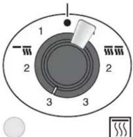
The neon indicator light by the grill control will come on.
Grill Operation
■ 1 - LOW for Melba toast (Setting 1)
■ 2 - MEDIUM for tomatoes, liver, cauliflower au gratin. (Setting 2)
■ 3 - HIGH for rare steak and toast. (Setting 3)
USING THE GRILL
Reversible Toasting Trivet
a) Open door and remove pan from storage position. Rest pan on compartment door.

natural_image
Technical line drawing of a rectangular grater or grater device mounted on a base plate (no text or symbols)b) Select full or half operation and switch to Low, Medium or High as indicated above. Pre-heat the grill for 5 minutes.
c) Load pan and position between the side supports at desired level or upon the base of the compartment. Ensure handle of grill pan does not enter the compartment. The toasting trivet can be turned over to give a further grilling position.
e) Depending on food type and amount being prepared, it may be necessary to turn food during cooking
f) After use, turn control OFF.
g) Allow compartment to cool before returning grill pan to storage position.
ACCESSIBLE PARTS MAY BE HOT WHEN THE GRILL IS IN USE.
IN USE
Grilling is a direct method of cooking where heat radiates down on the food. It is both quick and simple and can be used to prepare a wide and varied list of foods such as:
Whole Foods, Cuts of Meat or Fish, Made-up Dishes, Tomatoes, Herring, Lamb Chops, Salmon Steaks, Kebabs
These may be cooked by placing items on wire trivet or brander plate. In addition to this, the grill can also be used for the following:
Browning (Duchess Potatoes)
Gratinating (Cauliflower au Gratin)
Glazing (Fillets of Fish Bonne Femme)
Toasting (Bread, Tea Cakes, Melba Toast)
The heat is easily controlled and cooking times are dependent upon the following criteria:
Cut(s) of Meat or Fish (as applicable)
Freshness of Produce
Size and Weight of Produce
and perhaps most importantly, Personal Preference
Ultimately, it is experience that determines what type of food merits which setting.
CHEFS TIPS for GRILLING
Always pre-heat the grill prior to use.
Accessible parts may be hot when using the grill. Never turn grill on with the door closed or with the pan in the storage position.
When in use, the grill pan must be pushed to the compartment rear at the required level (compartment bottom or grill pan supports). The handle of the pan should never enter the compartment.
After use, store grill pan on the bottom of the grill compartment.
Grill Cooking Chart
| MEAT | Time (mins) |
| Back Bacon Rashers | 2 |
| Chicken Satay | 6 |
| Fillet Steak (170g) | 10 |
| Sirloin Steak (170g) | 10 |
| Hamburger (113g) | 8 |
| Lamb Chop | 12 |
| Lamb Kidneys | 8-9 |
| Lamb's Liver | 5 |
| Pork Chops | 12 |
| Pork Sausage (57g) | 8 |
| Pork Kebabs | 10 |
| FISH | Time (mins) |
| Cod Fillet | 7 |
| Halibut Steaks | 10-11 |
| Herring Fillets in Oatmeal | 7 |
| Lemon Sole Fillets | 5 |
| Salmon Steaks | 10 |
| Whole Mackerel | 11-12 |
| Whole Trout | 10 |
| MISCELLANEOUS | Time (mins) |
| Mush rooms | 3-4 |
| Toasted Cheese | 2 |
| Whole Tomatoes | 4-5 |
Brander Plate
The combination of heat from the element(s) above with that of the plate directly below the food helps to reduce conventional grilling times.
Seasoning The Brander Plate
a) The brander must be seasoned before use. When food begins to stick, the process needs to be repeated.
b) Pre-heat the oven to 200°C
c) Lightly oil brander and cover surface with cooking salt.
d) Place brander on a suitable baking tray and insert into oven for approximately 30 minutes.
e) Remove brander when salt turns light brown in colour.
f) Allow salt to cool before brushing away.
g) Dress brander surface with oil and burn on in oven for 5 minutes.
The plate is now ready for use.
Using the Brander Plate
a) Open door and remove pan from storage position. Sit branding plate in grill pan and lightly oil.
b) Select full or half operation and switch to Low, Medium or High as indicated above.
c) Insert grill pan within compartment and pre-heat brander for 5 minutes.
d) Load brander and position between the side supports at desired level or upon base of compartment. Ensure handle of grill pan does not enter compartment.
e) Turn food every 2 - 3 minutes to ensure even cooking and to achieve a branded effect.
f) After use, turn control OFF.
g) Allow compartment to cool before returning grill pan to storage position.
ACCESSIBLE PARTS MAY BE HOT WHEN GRILL IS IN USE.
The Ambient Drawer
USING THE AMBIENT DRAWER
Located directly below the right oven, this is not heated.
In normal circumstances, the drawer condition will be ambient temperature. On occasion however, it will absorb heat from the oven(s).
This provides an ideal condition in which to prove yeast goods such as croissants, bread and Chelsea buns.
Alternatively the drawer is ideal for the storage of roasting tins, baking trays and other cooking utensils.
Do not store any flammable material (e.g. pans with wooden handles).
The temperatures to be expected are as follows:
Food Item Condition Core Temp Range °C
| Beef Rare 50-55 | ||
| Beef Medium/Rare 55-60 | ||
| Beef Medium 60-65 | ||
| Beef Medium/Well done 65-75 | ||
| Beef Well done 75-80 | ||
| Lamb Medium 65-70 | ||
| Lamb | Well Done | 70-80 |
| Chicken | Cooked through | 80-85 |
| Duck | Cooked through | 70-75 |
| Fish | Cooked through | 70-75 |
| Gammon | Cooked through | 75-80 |
| Goose | Cooked through | 70-75 |
| Patés and Terrines | Cooked through | 75-80 |
| Pork | Cooked through | 80-85 |
| Turkey | Cooked through | 75-80 |
| Veal | Medium/Well done 65-75 | |
Cleaning
It is necessary to clean the unit regularly to help maintain performance, efficiency, hygiene and safety.
Whenever possible, wipe up spillages as they occur to prevent deposits becoming burnt-on. These can be difficult to remove. Allow unit to cool before commencing to clean it.
NEVER USE PAINT SOLVENTS, WASHING SODA, CAUSTIC CLEANERS, BIOLOGICAL POWDERS, COARSE ABRASIVES OR SALT.
Hob
It's very easy to clean the Hob with a recommended cleaner.
CAUTION — Do not use abrasive cleaners or pads, oven aerosols or pads or stain removers on the surface.
Daily care
First of all, be sure that all heat indicator lights are off and the cooking surface is cool. Apply a small dab, about the size of a 10p piece, of ceramic cooking cleaning cream in the centre of each area to be cleaned. Dampen a clean paper towel and work the cleaning cream on the cooking surface as if you were cleaning a window. As a final step, wipe the cooking surface with a clean, dry paper towel.
Cleaning for spills
For spills and boil-overs that occur while cooking, turn the unit off and wipe the area surrounding the hot zone with a clean paper towel. If a spill (other than a sugary substance) is on the hot zone, do not clean until the unit is completely cooled down and follow the instructions below ("Cleaning for burned-on spills"). If you accidentally melt anything on the cooking or if you spill foods with a high sugar content (preserves, tomato sauce, etc.), REMOVE the spill IMMEDIATELY with a razor scraper, while the unit is still hot. IMPORTANT: Use an oven glove to protect your hand from potential burns. Scrape the major spill or melted ma-
terial from the cooking zone and push into a cold area. Then, turn the unit "OFF" and allow to cool before cleaning further. After the cooking surface cools down and the heat indicator lights go off, use the daily care procedure as outlined above.
Cleaning for burned-on spills
Be sure that the heat indicator lights are off and the hob is cool. Remove excess burned-on substance with a single-edged razor scraper. Hold the scraper at approximately a 30^ angle to the surface and scrape off the burned-on matter as you would scrape paint off of a window.

natural_image
Illustration of a hand using a tool to apply material, no text or symbols presentIMPORTANT: Take care when using a sharp scraper.
When you have removed as much as possible with the scraper clean using the daily care procedure as described above.
To remove metal rub-off
Sliding pans on the hob - especially aluminium or copper pans can leave marks on the surface. These marks often appear like scratches, but can be easily removed using the procedure described above for cleaning spills. If the rub-off marks are especially stubborn, use the cleaning cream together with the razor scraper, using the technique described above.
Grill Pan, Trivet and Brander Plate
Remove stubborn particles from trivet or brander using a stiff brush or scouring pad. Clean in hot soapy water. Having prepared meat or foods that soil, leave to soak for a few minutes immediately after use.
Vitreous Enamelled Surfaces
Only use cleaners approved for use on vitreous enamel.
It is advisable to clean such surfaces daily after use. Wipe clean whilst still warm with a soft cloth soaked in hot, soapy water.
Badly stained areas should be cleaned by applying an approved detergent to hot water and removed using a nylon or Scotch Brite pad.
Oven
Cleaning is easier if carried out whilst oven is still warm. For removal and cleaning of roof, sides and rear linings (these have a special enamel finish) refer to cook and clean linings section which follows.
Cook and Clean Oven Linings
Coated with a special enamel, these effect self cleaning to reduce soil level.
The linings will be more effective if fat splash is kept to a minimum. This may be avoided by:
Covering meat with foil or a roasting bag.
Drying meat before placing in roasting tin
Lightly brush potatoes with fat before placing around meat
Lining stains are removed by means of oxidation when oven is heated. These will not always disappear if oven is only used at low temperatures.
If heavy splashing occurs, wipe linings with a lint free cloth and hot soapy water.
Dry linings thoroughly and replace before heating at 200^ C for approximately one hour.
Removing shelves may cause a metallic rubbing on linings; this is normal. Do not use abrasives, scrapers, knives, scourers, paste, bleach, steel wool, aerosol or proprietary pads on the linings.
It is not our claim that residue marks will not appear on these parts, only that they require the minimum of attention.
Removing the Oven Linings
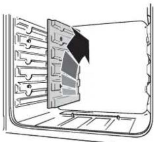
Some of the lining panels can be removed for cleaning and for cleaning behind. Remove the shelves first.
The right hand fanned oven has a removable oven roof - slide the roof liner forward and remove.

natural_image
Line drawing of a table with 'FRONT' label on the tray (no other text or symbols)The side panels of either oven can be removed.
Each side of the oven is fixed with four fixing screws.

natural_image
Technical line drawing of a mechanical component with internal channels and a triangular cutout (no text or symbols)Hanging Screws
You don't have to remove the screws to remove the oven linings. Lift each side panel upwards and they will slide off the screws. Then pull them forwards.
natural_image
Diagram of a door panel with a black arrow pointing to the interior panel (no text or symbols)Once the linings are removed, the oven enamel interior can be cleaned.
When replacing the linings fit the side linings first.
Make sure you fit the oven roof with the slot at the front.
Cleaning Brass Components
Uncoated natural brass is used as part of the authentic unit finish and may tarnish with age.
To regain a polished finish, these areas should be cleaned using a proprietary cleaner such as Brasso.
Troubleshooting
A crack has appeared in the Hob surface
Disconnect the cooker immediately from the power supply and arrange for its repair. Don't use the cooker until after the repair. See the Customer care leaflet for how to contact a service person.
My Hob is scratched
Have you used the correct cleaning methods?
Pots and pans with rough bottoms, or coarse particles (salt or sand) between the pan and the surface of the hob may cause scratches.
Use the recommended cleaning methods. Make sure pan bottoms are smooth and clean. Tiny scratches are not removable but will become less visible in time as a result of cleaning.
Metal markings on the Hob
Do not slide aluminium or copper pans across the surface. Marks from aluminium and copper pans as well as mineral deposits from water or food can be removed with the cleaning cream.
Steam is coming from the oven
When cooking foods with a high water content (e.g. oven chips) there may be some steam visible at the rear grille. Take care when opening the oven door as there may be a momentary puff of steam when the oven door is opened. Stand well back and allow any steam to disperse.
The oven fan is noisy
The note of the oven fan may change as the oven heats up - this is perfectly normal.
What cleaning materials are recommended for the cooker?
See the ‘Cleaning’ section of the Easy Guide for a full list of recommended cleaning materials. We do not recommend Mr. Muscle, as it contains chemicals that may damage the surfaces of your cooker.
The knobs get hot when I use the oven or the grill, can I avoid this?
Yes, this is caused by heat rising from the oven or the grill, and heating them up. Don't leave the oven door open. Make sure that the grill pan is pushed right back to the 'back stop' when grilling.
If there is an installation problem and I don't get my original installer to come back to fix it who pays?
You do. Service organisations will charge for their call outs if they are correcting work carried out by your original installer. It's in your interest to track down your original installer.
Current Operated Earth Leakage Breakers
Where the cooker installation is protected by a 30 milliamp sensitivity residual current device (RCD), the combined use of your cooker and other domestic appliances may occasionally cause nuisance tripping. In these instances the cooker circuit may need to be protected by fitting 100mA device. This work should be carried out by a qualified electrician.
Food is cooking too slowly, too quickly, or burning
Cooking times may differ from your previous oven. Check that you are using the recommended temperatures and shelf positions. See page 15. The oven control settings and cooking times are intended to be used only as a guide. Individual tastes may require the temperature to be altered either way, to get the results you want. Try cooking at a higher temperature setting. Is the oven roof in?
The oven is not cooking evenly
Do not use a tin or tray larger than 320mm x 305mm.
If you are cooking a large item, be prepared to turn it round during cooking.
If two shelves are used, check that space has been left for the heat to circulate. When a baking tray is put into the oven, make sure it is placed centrally on the shelf.
Check that the door seal is not damaged and that the door catch is adjusted so that the door is held firmly against the seal.
A dish of water when placed on the shelf should be the same depth all over. (For example, if it is deeper at the back, then the back of the cooker should be raised up or the front lowered). If the cooker is not level arrange for your supplier to level it for you.
Oven not coming on when turned on manually
Is the power on? Is the clock illuminated? If not there may be something wrong with the power supply. Is the cooker supply on at the isolator switch? Is the clock flashing 0.00? If so set it to the correct time of day. Has the Timer been set to AUTO by mistake? If AUTO is showing on the clock display, press the 'cook period' button and reduce any set cooking time showing to 0.00, with the (+) and (-) buttons.
Press the 📄 button twice. If this does not solve the problem contact a service person.
Oven not coming on when automatic cooking
Timer set correctly but oven knob left OFF by mistake?
Oven temperature getting hotter as the cooker gets older
If turning the knob down has not worked or only worked for a short time then you may need a new thermostat. This should be fitted by a service person.
Grill not cooking properly
Are you using the pan and trivet supplied with the cooker? Is the pan being used on the runners, not the floor of the compartment? Is the grill tray pushed fully back to stop?
The oven light is not working
The bulb has probably blown. You can buy a replacement bulb (which is not covered under the guarantee) from a good electrical shop. Ask for an Edison screw fitting 15w 240v lamp, FOR OVENS. It must be a special bulb, heat resistant to 300°C. See the Customer Care leaflet for spares by mail order.
Open the oven door and remove the Handyrack (if fitted) and oven shelves.
Turn off the power supply.
Unscrew the bulb cover by turning anticlockwise. Unscrew the old bulb. Screw in the new bulb, screw back the bulb cover. Turn on the electricity supply and check that the bulb now lights.
General Safety Instructions
The cooker must be installed by a qualified electrician in accordance with the installation instructions. It should be serviced by a qualified service engineer and only approved spare parts used. Have the installer show you the location of the cooker control switch. Mark it for easy reference. Always allow the cooker to cool and then switch off at the mains and before cleaning or carrying out any maintenance work, unless specified otherwise in this guide.
All parts of the cooker become hot with use and will retain heat even after you have stopped cooking.
Take care when touching the hob especially the marked cooking areas. The glass surface of the hob will retain heat after the controls have been turned off. To minimize the possibility of burns, always be certain that the hob controls are in the OFF position and that the entire glass surface is cool before attempting to clean the hob.
Use dry oven gloves when applicable - using damp gloves might result in steam burns when you touch a hot surface. Never operate the cooker with wet hands.
Do not use a towel or other bulky cloth in place of a glove. They might catch fire if they touch a hot surface.
Always turn the surface unit controls off before removing the pans.
Don't place utensils on the hob surface when it is in use. They may become hot and could cause burns.
Clean the hob with caution. If a wet sponge or cloth is used to wipe spills on a hot surface unit, be careful to avoid steam burns. Some cleansers can produce noxious fumes if applied to a hot surface.
Do not use unstable saucepans and position the handles away from the edge of the hotplate.
Babies, toddlers and young children should not be allowed near the cooker at any time. They should never be allowed to sit or stand on any part of the appliance. Teach them not to play with controls or any other part of the cooker.
Never store anything of interest to children in cabinets above a cooker - children climbing on the cooker to reach them could be seriously injured.
Clean only parts listed in this guide.
In the interests of hygiene and safety the cooker should be kept clean at all times as a build up in fats and other food stuff could result in a fire.
We recommend that you avoid wiping any surface unit areas until they have cooled and the indicator light has gone off. Sugar spills are the exception to this. Please see 'Cleaning your cooker'. When the hob is cool, use only the recommended cleaning cream to clean the hob.
To avoid possible damage to the cooking surface, do not apply the cleaning cream to the glass surface when it is hot. Read and follow all instructions and warnings on the cleaning cream labels. After cleaning, use a dry cloth or paper towel to remove any cleaning cream residue.
Avoid heating an empty pan. Doing so may damage the hob and the pan. Always keep combustible wall coverings or curtains etc. a safe distance away from your cooker.
Do not place or store items on top of the glass hob surface when it is not in use.
Do not spray aerosols in the vicinity of the cooker while it is in on.
Do not store or use combustible materials, or flammable liquids in the vicinity of this appliance.
Do not use water on grease fires. Never pick up a flaming pan. Turn the controls off. Smother a flaming pan on a surface unit by covering the pan completely with a well fitting lid or baking tray. If available use a multipurpose dry chemical or foam-type fire extinguisher.
Never leave the hob unattended at high heat settings. Pans boiling over can cause smoking and greasy spills may catch on fire.
Never wear loose-fitting or hanging clothes while using the appliance. Be careful when reaching for items stored in cabinets over the hob. Flammable material could be ignited if brought in contact with a hot surface unit and may cause severe burns.
Take great care when heating fats and oils, as they will ignite if they get too hot.
Use a deep fat thermometer whenever possible to prevent overheating fat beyond the smoking point.
Never leave a chip pan unattended. Always heat fat slowly, and watch as it heats. Deep fry pans should be only one third full of fat. Filling the pan too full of fat can cause spill over when food is added. If you use a combination of oils or fats in frying, stir them to-
gether before heating, or as the fats melt.
Foods for frying should be as dry as possible. Frost on frozen foods or moisture on fresh foods can cause hot fat to bubble up and over the sides of the pan. Carefully watch for spills or overheating of foods when frying at high or medium high temperatures. Never try to move a pan of hot fat, especially a deep fat fryer. Wait until the fat is cool.
When the grill is on, do not use the top of the flue (the slot along the back of the cooker) for warming plates, dishes, drying tea towels or softening butter.
When using an electrical appliance near the hob, be sure that the cord of the appliance does not come into contact with the surface area.
If you find a crack in the hob surface immediately disconnect the appliance from the supply and arrange for its repair.
Take care that no water seeps into the appliance
Only certain types of glass, glass-ceramic, earthenware or other glazed containers are suitable for hob cooking; others may break because of the sudden change in temperature.
Use proper pan size-select pans having flat bottoms large enough to cover the surface unit's heating area. The use of undersized pans will expose a portion of the surface unit to direct contact and may result in ignition of clothing. Proper relationship of pans to surface unit will also improve efficiency.
Do not allow anyone to climb, stand or hang on any part of the cooker.
Do not use aluminium foil to cover shelves, linings or the oven roof.
Make sure that your kitchen is well ventilated at all times. Use extractor fans or hoods when fitted.
Never heat unopened food containers. Pressure build up may make container burst and cause injury.
The cooker is designed for cooking foods only and must not be used for any other purpose.
The oven should NOT be used for heating the kitchen, not only does this waste fuel but the control knobs may become overheated.
When the oven is on DO NOT leave the oven door open for longer than necessary.
The specification of this cooker should not be altered.
This appliance is heavy, take care when moving it.
When the cooker is not in use ensure that the control knobs are in the off position.
Do not slide pans across the hob because this can scratch the glass - the glass is scratch resistant, not scratch proof. Sharp instruments, rings or other jewellery and rivets on clothing could scratch the hob surface.
Do not use the surface as a cutting board.
Don't store heavy items above the hob. If they drop on the hob, they could cause damage.
Optional Extras
Splashback Fitting Instructions

The splashback should be positioned on the wall in line with the unit bottom edge, 75mm below hob level. 4 x ∅ 5mm holes require to be drilled 7.5mm from the splashback edge at top and bottom.
Position panel against wall. Mark fixing locations through existing holes.
Drill ∅ 6mm holes in the wall and push the raw|plugs provided fully home into these holes.
Position splashback and secure to wall using the fixings provided.
Utensil Rack Fitting Instillation
UTENSIL RACK KIT CONTENTS
Item Description No. Off
| A Brass Backing Plate 2 |
| B Brass Rail End 2 |
| C Countersunk Screw (M5) 4 |
| D Stainless Steel Rail I |
| E Rawlplug 4 |
| F Brass Countersunk Screw 4 |
Important Note
It is not advisable to install the utensil rack directly above the appliance flue.

I. Secure the backing plates (A) to the rail ends (B) using the fixings (C).
2. Slide both ends on to the rail.
3. Hold the assembled rack in the required position against the wall and mark the location points through the fixing holes.
4. If using the rawplugs (E) provided, drill 4 x ∅ 6mm holes and push the plugs fully home into these.
5. Secure the rack to the wall using the brass fixings (F)
Flue Spacer Fitting Instructions

- Working from the unit rear, remove the fixings that secure the flue capper to the hob. The centre fixing should be removed last. When this has been removed, the flue clamp plate will loosen. Allow the plate to rest on the two flue boxes.
- Remove the flue capper.
- Position the flue spacer on the hob and align the fixing holes.
- Starting with the centre fixing, secure the flue spacer to the hob and tighten. Ensure that the flue clamp plate has been repositioned.
Installation and Servicing Instructions
This appliance must be installed and serviced by a competent person.
IMPORTANT
The unit shall be installed in accordance with the regulations in force at the time. Read the instructions thoroughly before installation and subsequent use.
In the UK, regulations and standards are as follows -
BS 6891 :1988
Health And Safety At Work etc. Act
BS 7671 I.E.E. Regulations for Electrical Installations
Local and National Building Regulations
Electricity at Work Regulations
Fire Precautions Act
The appliance has been CE-marked on the basis of compliance with the Low
Voltage and EMC directives for the voltage stated on the data plate.
WARNING - ALL APPLIANCES MUST BE EARTHED
On completion of the installation, this manual should be left with the Engineer-in-Charge for reference during servicing. Further to this, The Users Manual should be handed over to the Owner, having had a demonstration of the operation and cleaning of the unit.
IT IS IMPORTANT THAT THESE INSTRUCTIONS BE CONSULTED PRIOR TO INSTALLING AND COMMISSIONING THIS APPLIANCE.
FAILURE TO COMPLY WITH THE SPECIFIED PROCEDURES MAY RESULT IN DAMAGE OR THE NEED FOR A SERVICE CALL.
SECTION 1 - INSTALLATION
UNLESS OTHERWISE STATED, PARTS WHICH HAVE BEEN PROTECTED BY THE MANUFACTURER ARE NOT TO BE ADJUSTED BY THE INSTALLER.
1.1 MODEL NUMBERS, NETT WEIGHTS AND DIMENSIONS
Model Width Depth Height Weight
211-EEO 1100mm 600mm 935mm 140kg
1.2 SITING
1.2.1 Positioning the Appliance (see Figure 1)

Figure 1
The unit is supplied with two rear and one centre front roller for movement purposes.
To position the range, first remove the kicking strip from the bottom front of the unit. Pull open the drawer to the furthest point and lift and pull it forward to remove. The screw that lowers the front roller is positioned at the LH side of the drawer opening on the centre support beam.
Place the flat end of the spanner over the square drive peg and turn this clockwise until the front beam and feet are clear of the floor. Use the hex end of the spanner to turn the two adjusting nuts, positioned at either bottom front corner. Six complete turns clockwise will lower the back rollers and raise the unit rear.
The unit may now be pushed into position.
THE APPLIANCE MUST NOT BE PUSHED, PULLED OR LIFTED BY THE TOWEL RAIL OR DOOR HANDLES.
WARNING - SERVICING TO BE CARRIED OUT ONLY BY AN AUTHORISED PERSON Disconnect from electricity supply before servicing. Check appliance is safe when you have finished.
Note
Ensure that the floor covering below the range is firmly fixed or removed to prevent disturbance whilst positioning the appliance.

natural_image
Technical line drawing of a mechanical assembly with rotating components and directional arrows (no text or symbols)Figure 2
1.2.2 Levelling
The unit must be levelled following placement. The height at the back is adjusted by using the hex end of the spanner on the rear rollers. The front is levelled by initially turning the adjusting screw of the near roller clockwise until the desired height is achieved. Following this, position the levelling feet by screwing them down. When the unit is level, turn the front roller adjuster anti-clockwise until the weight is transferred from the roller to the feet.
1.2.3 APPLIANCE LOCATION
The unit may be installed in a kitchen/kitchen diner but not in a room that contains a bath or shower.
1.2.4 Position of Appliance
The space required above the hotplate is indicated in Figure 1.
A width of 1115mm is required up to hotplate level to accommodate the additional width required when the doors are opened fully.
A minimum overhead distance of 800mm is required above the hob.
Curtains must not be fitted immediately behind the appliance.
Any extraction hood should be installed in accordance with the manufacturer's instructions.
1.3 ELECTRICAL SUPPLY
1.3.1 ELECTRICAL CONNECTION
This appliance must be installed by a qualified electrician to comply with the relevant Institute of Electrical Engineers (I.E.E.) regulations and also local electricity supply company requirements.
WARNING - THIS APPLIANCE MUST BE EARTHED!
Note: The unit must be connected to the correct electrical supply as stated on the data label. A suitable control unit which incorporates a double pole switch with contact separation of at least 3mm in all poles must be fitted. This type of unit should NEVER be connected to a regular power socket.
With diversity taken into consideration, we recommend the use of a 40 - 45 amp cooker point.
Access to mains terminal is gained by removing electrical terminal cover box on back panel. Connect mains cable to terminals as indicated below.

Fig. 4
The unit is Type X with regard to protection against the over-heating of surrounding surfaces.
Current Operated Earth Leakage Breakers
In the event of an installation being protected by a 30mA sensitivity residual current device (RCD), the combined use of the unit and other domestic appliances may occasionally cause nuisance tripping. In such instances, the cooker circuit may require to be protected by fitting a 100mA device. Such work should be carried out by a qualified electrician.
1.4 ELECTRICAL RATINGS
1.4.1 Hob Element Ratings (230V - 50hz)
Hob Element Rating
| Front Left 1.1kW |
| Rear Left 1.4kW |
| Rear Right 1.1kW |
| Front Right 1.1kW |
| Centre 2.7kW |
1.4.2 ADDITIONAL ELECTRICAL RATINGS (230V - 50HZ)
LH Oven - 2.0kW Browning Element 1.05kW
| RH Oven - 2.3kW | Grill Element | 2.1kW |
SECTION 2 - ASSEMBLY and COMMISSIONING
2.1 ASSEMBLY
After unpacking unit, check following parts -
Part No. Off
Oven Shelves 4
Grill Pan and Grid I
Ceramic Hob Scraper 1
Roasting Tin with Trivet 2
Cake Rack 2
Handy Rack 1
User's Manual 1
2.2 CONNECTION TO THE ELECTRICITY SUPPLY
Refer to Section 1.3 of this manual.
2.4 PRE-COMMISSIONING CHECK
Check hob elements in turn. Turn control knob to full on position and leave hob for a few seconds before checking that heat is radiating from the element.
When check is complete, turn control off and repeat this procedure for the remaining elements. Check also that the residual heat indicator remains lit until the corresponding element cools.
SECTION 3 - SERVICING
3.1 SERVICING
Disconnect from electricity supply before commencing servicing, particularly before removing any of the following:- control panel, side panels, ceramic hob or any electrical components or covers.
Before restoring power, make connection checks as detailed in Section 1.3. Note - References to LH and RH oven apply as viewed from the front.
3.2 TO REMOVE CONTROL PANEL
Disconnect appliance from electricity supply.
a) Remove control knobs from all taps.
b) Open grill and RH oven doors. Remove 3 fixings on top front and 3 fixings on control panel underside.
c) Pull control panel forward. Remove connections from rear of three neons. Disconnect earth lead and lift panel clear of unit.
d) Replace all parts in reverse order.
e) When replacing any electrical connections refer to the wiring diagram on Pages 16 and 17.
3.3 TO REMOVE CERAMIC HOB
Disconnect appliance from electricity supply. Pull unit forward to gain access.
The ceramic hob material is much more sensitive to scratches on the underside than the top.
Take care not to touch or scratch the underside of the ceramic as this will weaken the material and cause the top to shatter.
a) Remove control panel as detailed in Section 3.2.
b) Remove fixing screws on hob underside (2 - front, 4 - rear).
c) Lift rear and slide ceramic hob forward.
d) Lift ceramic hob clear of appliance taking care not to damage elements.
e) Replace in reverse order.
3.4 TO REMOVE AN OUTER SIDE PANEL
Disconnect the appliance from the electricity supply.
a) Remove control panel as detailed in Section 3.2.
b) Remove retaining screw on upper front edge and two fixings on rear of the side panel. Undo lower retaining screw situated below the edge at panel front corner.
c) Remove panel by pulling it away from unit. If this is difficult, it may be necessary to slacken the two closest hob fixing screws
d) Replace parts in reverse order.
3.5 TO REMOVE A RESIDUAL HEAT INDICATOR
Disconnect appliance from electricity supply.
a) Remove control panel as detailed in Section 3.2.
b) Remove ceramic hob as detailed in Section 3.3.
c) Disconnect the indicator leads.
d) Remove indicator from bracket.
c) Replace all parts in reverse order.
Ensure replacement indicator functions correctly.
3.6 TO REMOVE OVEN/GRILL NEON
Disconnect appliance from electricity supply.
a) Remove control panel as detailed in Section 3.2.
b) Remove relevant connection and undo nut securing neon to control panel.
c) Replace parts in reverse order. Ensure replacement functions correctly.
3.7 TO REMOVE A THERMOSTAT
Disconnect appliance from electricity supply.
a) Remove control panel as detailed in Section 3.2.
b) Remove ceramic hob as detailed in Section 3.3.
c) Open appropriate oven door and remove shelves and linings. For RH oven, slide roof liner away and remove fixings securing thermostat phial cover.
d) Unclip thermostat phial from clips in oven back panel.
e) For LH oven, pull unit forward to access cover box at rear. Remove cover fixings and lift clear.
f) Feed thermostat capillary clear of oven.
g) Disconnect wires from thermostat and undo fixings that secure control to mounting plate.
h) Fit replacement and re-assemble in reverse order. Ensure phial is clipped to oven rear and positioned centrally between the clips. Check thermostat functions correctly.
3.8 TO REPLACE A GRILL CONTROLLER
Disconnect appliance from electricity supply.
a) Remove control panel as detailed in Section 3.2.
b) Remove ceramic hob as detailed in Section 3.3.
c) Disconnect leads and undo fixings which secure device to mounting plate.
d) Fit replacement and re-assemble in reverse order. Check replacement functions correctly.
3.9 TO REMOVE AN OVEN CUT-OFF THERMOSTAT
Disconnect appliance from electricity supply.
a) Pull unit forward to gain access to cover box. Undo cover screws and lift clear.
b) Control is located on earth plate beside oven element connections.
c) Disconnect thermostat wiring. Undo fixings that secure thermostat to earth plate and remove.
d) Fit replacement control and re-assemble parts in reverse order.
3.10 TO REMOVE A HOB ELEMENT ENERGY REGULATOR
Disconnect appliance from electricity supply.
a) Remove control panel as detailed in Section 3.2.
b) Remove ceramic hob as detailed in Section 3.3.
c) Disconnect regulator wiring and undo fixings that secure device to mounting panel.
d) Fit replacement and re-assemble parts in reverse order. Check replacement functions correctly
3.11 TO REMOVE A HOB ELEMENT
Disconnect appliance from electricity supply.
a) Remove ceramic hob as detailed in Section 3.3.
b) Disconnect element wiring.
c) Remove element spring from locating bracket by undo-
ing nut below bracket and lifting element directly upward.
d) Undo screws that secure spring to element.
e) Fit spring to new element using existing fixing holes.
f) Re-assemble parts in reverse order. Check replacement functions correctly.
3.12 TO REMOVE OVEN DOOR
a) Open oven door and remove Handyrack (where fitted) by removing one locating spar from bracket on the door. Slide other spar free.
b) Support door and remove fixings that secure upper hinge to unit front frame.
c) Remove door from lower hinge by lifting slightly and moving it outward.
d) Re-assemble in reverse order.
3.13 TO REMOVE GRILL DOOR
a) Remove control panel as detailed in Section 3.2.
b) Remove ceramic hob as detailed in Section 3.3.
c) Remove LH side panel as detailed in Section 3.4.
d) Remove kick plate (4 screws).
e) Remove central vertical cover situated between ovens. (5 screws).
f) Remove 2 countersunk screws (1 per side) which secure hinge arms to front of grill chamber.
Note
The door hinge arms are spring tensioned. Carefully remove grill door and retain the gaskets.
g) Re-assemble in reverse order. Ensure gasket is fitted between hinge arm and front of grill chamber. Check door operation.
3.14 TO REMOVE OVEN OUTER DOOR PANEL
a) Open the oven door.
b) Remove two screws 'A' and two screws 'B' from the door.
c) Remove the outer door panel.
d) Undo the nuts that secure the handle to the door panel. Fit the handle to the replacement door panel.
e) Fit the replacement panel to the oven inner door.
f) Re-assemble in reverse order.
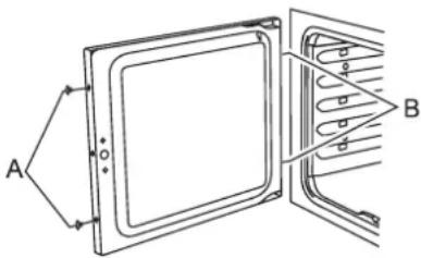
3.15 TO REMOVE DOOR LATCH
a) Remove oven outer door panel as detailed in Section 3.14.
b) Remove fixings which secure latch assembly to inner door panel. (See Figure 4).
c) Fit replacement catch and re-assemble in reverse order.
d) Check correct operation of door.
3.16 TO REMOVE OVEN DOOR SEAL

natural_image
Illustration of a hand holding a metal bracket with an arrow pointing to a detail (no text or symbols present)a) Remove outer door panel as detailed in Section 3.14.
b) Remove door bedding strip by sliding from clips on rear face of inner door panel see Figure 5).
c) Fit replacement door seal and re-assemble in reverse order.
3.17 TO ADJUST OVEN DOOR CATCH KEEPER
a) Open oven door and slacken locknut at keeper base.
b) Adjust keeper in or out as required, until desired door operation is obtained.
c) Re-tighten locknut.
3.18 TO REMOVE OVEN LININGS
a) Open oven doors and remove shelves.
b) Slide oven roof lining forward to remove it. (RH oven only)
c) Slide oven base forward and remove.
d) Lift oven side linings away from hanging screws and remove lining.
e) Replace all linings in reverse order.
3.19 TO REMOVE RH OVEN INNER BACK
a) Open RH oven door and remove fixings that secure inner back to oven rear.
b) Lift removable panel away.
c) Re-assemble in reverse order. Ensure retaining fixings are fully tightened.
3.20 TO REPLACE RH OVEN FAN
Disconnect appliance from electricity supply.
a) Pull unit forward to access cover boxes at appliance rear. Remove fixings that secure cover and lift it clear.
b) Remove fan wiring, noting connection positions.
c) Remove inner back as detailed in Section 3.19.
d) Hold fan blades and undo centre nut (LH thread), brass washers, fan blade and circlip.
e) Undo fixings that retain fan and remove it from the cavity rear.
f) Fit replacement and re-assemble parts in reverse order. Check oven operates satisfactorily.
3.21 TO REMOVE RH OVEN ELEMENT
Disconnect appliance from electricity supply.
a) Pull unit forward to access cover boxes at unit rear. Remove fixings that secure cover and lift it clear.
b) Undo terminal connections, noting their positions.
c) Remove inner back as detailed in Section 3.19.
d) Remove fixings that secure element within oven and lift element away carefully.
e) Fit the replacement element and re-assemble parts in reverse order.
f) Check oven operates correctly.
3.22 TO REMOVE LH OVEN ELEMENTS
Disconnect appliance from electricity supply.
3.22.1 Bottom Element
a) Pull unit forward to access cover boxes at unit rear. Remove fixings that secure cover and lift it clear.
b) Undo terminal connections, noting their positions.
c) Remove fixings that secure bottom element cover.
d) Undo terminal connections, noting their positions.
e) Remove the lower element support fixings.
f) Remove element bracket fixings and withdraw element.
g) Replace element and re-assemble parts in reverse order.
3.22.2 Top Element
a) Open LH oven door and undo fixings that secure heat shield.
b) Remove top element bracket fixings and withdraw element.
c) Replace element and re-assemble parts in reverse order. Check oven operates satisfactorily.
3.23 TO REMOVE GRILL ELEMENT
Disconnect appliance from electricity supply.
a) Pull unit forward to access the cover boxes at the appliance rear. Remove fixings that secure cover and lift it clear.
b) Undo terminal connections, noting their positions.
c) Remove grill pan.
d) Remove fixings that secure element front support from within chamber.
e) Remove fixing from each element and withdraw elements from chamber.
f) Fit replacement element(s) and re-assemble parts in reverse order. Check grill operation.
WARNING - SERVICING TO BE CARRIED OUT ONLY BY AN AUTHORISED PERSON Disconnect from electricity supply before servicing. Check appliance is safe when you have finished.
Circuit Diagram Top

Circuit Diagram Bottom

AGA FOODSERVICE GROUP
Clarence Street, Royal Leamington Spa,
Warwickshire, CV31 2AD, England.
Tel: +44 (0) 1926 457400 Fax: +44 (0) 1926 450526
E-mail: consumers@rangemaster.co.uk


- Contents
- GEO Dual Fuel Range
- Control Panel Layout
- General
- Information
- I.E.E Regulations for Electrical Installations
- Health and Safety at Work Act
- Warning - THIS APPLIANCE MUST BE EARTHED!
- CUSTOMER CARE
- YOUNG CHILDREN SHOULD NOT BE ALLOWED NEAR THE APPLIANCE.
- Note
- Warranty & Service
- Be safe
- The Hob
- The centre hob area has 3 elements.
- The right hand front hob area has two elements.
- 8
- WARNING
- 9
- 10
- 11
- Oven Operation
- The Ovens
- Right Hand Oven - Fan Assisted
- Left Hand Oven - Conventional Oven
- To Operate either Oven
- Using The Browning Element
- Important Note
- Oven Fitments
- Oven Roof (Right Hand Oven only)
- Shelves
- To Fit the Handyrack (Left Hand Oven only)
- Roasting Tin with Integral Trivet
- To Reduce Fat Splash
- Baking Trays
- Cooking Hints
- Shelf 3 Ribs of Beef
- USING A PROBE
- Left Hand Oven Cooking Chart
- Right Hand Fan Oven Cooking Chart
- Grill Operation
- To Operate Grill
- USING THE GRILL
- Reversible Toasting Trivet
- IN USE
- CHEFS TIPS for GRILLING
- Brander Plate
- Seasoning The Brander Plate
- The plate is now ready for use.
- Using the Brander Plate
- The Ambient Drawer
- Cleaning
- Hob
- Daily care
- Cleaning for spills
- Cleaning for burned-on spills
- To remove metal rub-off
- Grill Pan, Trivet and Brander Plate
- Vitreous Enamelled Surfaces
- Oven
- Cook and Clean Oven Linings
- Removing the Oven Linings
- Cleaning Brass Components
- Troubleshooting
- A crack has appeared in the Hob surface
- My Hob is scratched
- Metal markings on the Hob
- Steam is coming from the oven
- The oven fan is noisy
- What cleaning materials are recommended for the cooker?
- The knobs get hot when I use the oven or the grill, can I avoid this?
- If there is an installation problem and I don't get my original installer to come back to fix it who pays?
- Current Operated Earth Leakage Breakers
- Food is cooking too slowly, too quickly, or burning
- The oven is not cooking evenly
- Oven not coming on when turned on manually
- Oven not coming on when automatic cooking
- Oven temperature getting hotter as the cooker gets older
- Grill not cooking properly
- The oven light is not working
- General Safety Instructions
- Optional Extras
- Splashback Fitting Instructions
- Utensil Rack Fitting Instillation
- UTENSIL RACK KIT CONTENTS
- Flue Spacer Fitting Instructions
- Installation and Servicing Instructions
- IMPORTANT
- WARNING - ALL APPLIANCES MUST BE EARTHED
- SECTION 1 - INSTALLATION
- MODEL NUMBERS, NETT WEIGHTS AND DIMENSIONS
- SITING
- WARNING - SERVICING TO BE CARRIED OUT ONLY BY AN AUTHORISED PERSON Disconnect from electricity supply before servicing. Check appliance is safe when you have finished.
- Levelling
- APPLIANCE LOCATION
- Position of Appliance
- ELECTRICAL SUPPLY
- ELECTRICAL CONNECTION
- ELECTRICAL RATINGS
- Hob Element Ratings (230V - 50hz)
- ADDITIONAL ELECTRICAL RATINGS (230V - 50HZ)
- SECTION 2 - ASSEMBLY and COMMISSIONING
- ASSEMBLY
- CONNECTION TO THE ELECTRICITY SUPPLY
- PRE-COMMISSIONING CHECK
- SECTION 3 - SERVICING
- SERVICING
- TO REMOVE CONTROL PANEL
- TO REMOVE CERAMIC HOB
- TO REMOVE AN OUTER SIDE PANEL
- TO REMOVE A RESIDUAL HEAT INDICATOR
- TO REMOVE OVEN/GRILL NEON
- TO REMOVE A THERMOSTAT
- TO REPLACE A GRILL CONTROLLER
- TO REMOVE AN OVEN CUT-OFF THERMOSTAT
- TO REMOVE A HOB ELEMENT ENERGY REGULATOR
- TO REMOVE A HOB ELEMENT
- TO REMOVE OVEN DOOR
- TO REMOVE GRILL DOOR
- TO REMOVE OVEN OUTER DOOR PANEL
- TO REMOVE DOOR LATCH
- TO REMOVE OVEN DOOR SEAL
- TO ADJUST OVEN DOOR CATCH KEEPER
- TO REMOVE OVEN LININGS
- TO REMOVE RH OVEN INNER BACK
- TO REPLACE RH OVEN FAN
- TO REMOVE RH OVEN ELEMENT
- TO REMOVE LH OVEN ELEMENTS
- Bottom Element
- Top Element
- TO REMOVE GRILL ELEMENT
- AGA FOODSERVICE GROUP
Brand : FALCON
Model : 211 EEO Ceramic
Category : Cooker