
GF 3 - Heating JOTUL - Free user manual and instructions
Find the device manual for free GF 3 JOTUL in PDF.


| Product Type | Gas Fireplace |
| Brand | Jøtul |
| Model | GF 3 |
| Category | Heating |
| Dimensions (H x W x D) | 600 mm x 700 mm x 400 mm |
| Weight | 80 kg |
| Power Supply | 230 V AC, 50 Hz |
| Ignition Type | Electronic ignition |
| Fuel Type | Natural gas or propane |
| Heat Output | 5 - 15 kW |
| Efficiency | Up to 85% |
| Control Type | Remote control and manual override |
| Flame Adjustment | Variable flame height |
| Thermostat | Integrated programmable thermostat |
| Glass Type | Ceramic safety glass |
| Safety Features | Overheat protection, flame failure device, child lock |
| Maintenance | Clean glass with non-abrasive cleaner; annual professional inspection |
| Spare Parts Available | Burner assembly, glass pane, control board, igniter |
| Installation | Must be installed by a qualified professional |
| Warranty | 2 years standard |
Frequently Asked Questions - GF 3 JOTUL
User questions about GF 3 JOTUL
0 question about this device. Answer the ones you know or ask your own.
Ask a new question about this device
Download the instructions for your Heating in PDF format for free! Find your manual GF 3 - JOTUL and take your electronic device back in hand. On this page are published all the documents necessary for the use of your device. GF 3 by JOTUL.
USER MANUAL GF 3 JOTUL
Conventional Fluid Gas Stove
Joftul GF 3 CF 2

natural_image
Architectural line drawing of a Gothic-style cabinet with arched windows and legs (no text or symbols)Installation and Operation Instructions

WARNING: If the information in these instructions is not followed exactly, a fire or explosion may result causing property damage, personal injury or death.
- Do not store or use gasoline or other flammable vapors and liquids in the vicinity of this or any other appliance.
- WHAT TO DO IF YOU SMELL GAS
- Do not try to light any appliance.
- Do not touch any electrical switch; do not use any phone in your building.
- Immediately call your gas supplier from a neighbor's phone. Follow the gas supplier's instruction.
- If you cannot reach your gas supplier, call the fire department.
- Installation and service must be performed by a qualified installer, service agency or the gas supplier.
Jøtul GF 3 CF 2
INSTALLATION SIGNATURE FORM
With proper usage and maintenance, this appliance will serve its owner adequately for many years. Please contact your Jøtul dealer for assistance if any problems should arise with your Jøtul appliance. Save this user manual and make sure it is available for service personnel.
Model Name: Jøtul GF 3 CF 2
Serial No.:
Purchase Date:
Name of Installer:
Fuel Type:
Was the appliance converted?
Notes:
Annual service - year 1 Sign.:
Company: Date:
Service details:
Annual service - year 2 Sign.:
Company: Date:
Service details:
Annual service - year 3 Sign.:
Company: Date:
Service details:
Annual service - year 4 Sign.:
Company: Date:
Service details:
Annual service - year 5 Sign.:
Company: Date:
Service details:
Annual service - year 6 Sign.:
Company: Date:
Service details:
Annual service - year 7 Sign.:
Company: Date:
Service details:
Annual service - year 8 Sign.:
Company: Date:
Service details:
Annual service - year 9 Sign.:
Company: Date:
Service details:
Annual service - year 10 Sign.:
Company: Date:
Service details:
Annual service - year 11 Sign.:
Company: Date:
Service details:
Annual service - year 12 Sign.:
Company: Date:
Service details:
Annual service - year 13 Sign.:
Company: Date:
Service details:
Annual service - year 14 Sign.:
Company: Date:
Service details:
Annual service - year 15 Sign.:
Company: Date:
Service details:
Annual service - year 16 Sign.:
Company: Date:
Service details:
Annual service - year 17 Sign.:
Company: Date:
Service details:
Annual service - year 18 Sign.:
Company: Date:
Service details:
THIS OWNER'S MANUAL PROVIDES INFORMATION TO ENSURE SAFE INSTALLATION AND EFFICIENT, DEPENDABLE OPERATION OF YOUR STOVE. PLEASE READ THESE INSTRUCTIONS IN THEIR ENTIRETY AND MAKE THEM AVAILABLE TO ANYONE USING OR SERVICING THIS GAS STOVE.
Table of Contents
- Technical Information .... 4
- General Information 5
- Safety Information .... 5
- Installer Information ......6
- User Information ......12
- Troubleshooting...... 14
Jøtul GF 3 CF 2 Technical Information
Material: Cast iron/steel
Finish: Blue Black enamel or Matte Black paint
Flue outlet: Top or Rear
Vent system: BV-standard system
Weight: Approx. 71 kg (product)
PIN: 0063BS5908
Product dimensions: See fig. 1.
| Countries of Destination | GB, IE | |
| Appliance Category II | _2H_3P | |
| Gas Types NG LPG | (G_20)^1 | (G_31)^2 |
| State of Adjustment I | _2H | I_3P |
| Supply Pressure (mbar) | 20 | 37 |
| Nominal Heat Input (Nett, kW) | 6.3 | 6.8 |
| Maximum Gas Consumption at Full Rate: ( m^3/h at 15°C 1013.25mbar) | 0.666 | 0.278 |
| Maximum Gas Consumption at Full Rate: (kg/h at 15°C 1013.25mbar) | - | 0.528 |
| Burner Pressure at Full Rate – Hot (mbar): | 9.10 | 26.9 |
| Efficiency:Rear Flue (Nett, %)Top Flue (Nett, %) | 80.679.9 | 80.979.5 |
| Efficiency Class | 2 2 | |
| NOx Class | 5 5 | |
| Main Burner Injector Marking | 235 | 140 |
| Pilot Injector Marking | 51 | 30 |
| Notes:The appliance is supplied at the default factory settings for Natural Gas (G20 at 20mbar)The appliance will have this setting following conversion to LPG (G31 at 37mbar) | ||
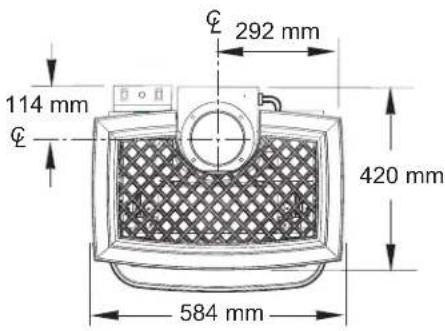
Figure 1. Top view dimensions.

Figure 2. Front view dimensions.

Figure 3. Side view dimensions.
General Information
This product has been approved to the European Standard EN 613:2000 and is in accordance with EC Gas Appliances Directive (90/396/EEC).
The Flue must be checked for soundness and swept prior to installation it should only be used if clean and in good order.
Before installation, ensure that the local distribution conditions and the adjustment of the appliance are compatible.
This appliance incorporates a spillage monitoring device (TTB) this device will shutdown the appliance in the event of interruption to the evacuation of combustion products. I.e. Flue Blockage.
If the appliance spillage monitoring device (TTB) should operate and close down the appliance, a minimum period of 3 minutes should be observed before following the lighting instructions detailed in the USER section of this manual.
If the appliance spillage monitoring device (TTB) shuts down the appliance repeatedly the appliance should not be used and a qualified service engineer should be called for service.
This product, the Jøtul GF 3 CF2, may only be used with Natural Gas G20 or be converted for the use of Propane G31.
Assembly, installation and maintenance must be performed by a qualified person in accordance with the instructions for assembly, Installation and use enclosed with the product. The installation may only be operated after it has been inspected by a qualified person and a certificate of completion has been issued.
The Installation should be carried out in accordance with the Building Regulations which include the following standards for installation and maintenance of flues, ventilation and installation of Gas Fires. For UK BS5440:1, BS5440:2, BS5871 for Republic of Ireland IS813, ICP3, IS327
The appliance is designed as a freestanding unit and no additional fixing methods need apply.
This appliance is intended for use on a gas installation with a governed gas supply.
Safety Precautions
This appliance must be installed in accordance with the rules in force. Consult instructions before installation and use of this appliance.
The appliance is designed as a heating device and all components will become hot (excluding control knob, control cover and control switch) care should be taken not to touch unit when it is in operation.
■ Warning! If you detect an odour of gas:
- Do not light the Stove or any other appliance.
- Do not use electrical switches or the telephone.
- Contact your gas supplier's emergency number.
The appliance must only be installed and repaired by qualified personnel. Always turn off the gas supply before service.
The appliance must be inspected following installation and at least once a year by qualified personnel.
The appliance must only use gas of the correct type and pressure. See technical data for more details.
If Propane G31 is to be used, the appliance must be converted using the conversion instructions and kit supplied by Jøtul. This is only to be installed by qualified personnel.
It is permitted to install the appliance against a wall made of combustible material with the clearances specified in figs. 5-6.
The minimum clearance to combustible material in front of the appliance is 600 mm.
■ Curtains may not be placed within 600mm above the appliance.
■ Never store combustible gas or liquid in the same room with the appliance.
■ Never light the appliance without the front glass in place or if the glass is cracked. Replacement of the glass should be done by a licensed or qualified service person. Only remove glass for routine service. Always handle glass carefully.
■ Do not burn solid fuel in the appliance.
- Do not place combustible material on or near the appliance, as the appliance becomes hot.
This appliance becomes hot in use so it advisable to keep young children, the aged or infirm and animals at a safe distance using a fireguard conforming to BS6539 or BS6778 to provide extra protection.
Installer Information
The Flue must be checked for soundness and swept prior to installation it should only be used if clean and in good order.
Before installation, check that the local distribution conditions, nature of the gas and pressure, and the adjustment of the appliance are compatible.
Assembly, installation, maintenance and gas conversion (if required) must be performed by a qualified person in accordance with the instructions for assembly, Installation and use enclosed with the product. The installation may only be operated after it has been inspected by a qualified person and a certificate of completion has been issued.
The Installation should be carried out in accordance with the Building Regulations which include the following standards for installation and maintenance of flues, ventilation and installation of Gas Fires. For UK BS5440:1, BS5440:2, BS5871 for Republic of Ireland IS813, ICP3, IS327
The appliance is designed as a heating device and all components will become hot (excluding control knob, control cover and control switch) care should be taken not to touch unit when it is in operation.
This appliance incorporates a spillage monitoring device (TTB) this device will shutdown the appliance in the event of interruption to the evacuation of combustion products. I.e. Flue Blockage.
WARNING:
The TTB shall not be adjusted by the installer.
The TTB shall not be put out of operation by the installer.
When the TTB is exchanged; only original manufacturer's parts shall be used.
Installation Guide for Qualified Personnel
Important: The appliance is factory pre-set for Natural Gas G20. If Propane G31 is to be used, the appliance must be converted with a conversion kit. The instructions are enclosed with the conversion kit. The kit is only to be installed by qualified personnel.
Fixing
The GF3 CF2 is designed as a freestanding appliance and as such does not require additional fixing.
Requirements for Floor Plate
The appliance may stand on a wooden floor. A floor plate of non-combustible material is required if the appliance is to be placed on carpet, vinyl, linoleum or other combustible material. Minimum dimensions of the floor plate: 580 x 435 mm as in fig. 4.

Figure 4. Minimum Hearth Protection.
Firewall Requirements
The appliance may be placed directly against a wall made of combustible material with the clearances specified in fig. 5. Make sure there is adequate space for the vent system behind the appliance and for the full height/length of the pipe.
Position of Appliance
Minimum clearances are as follows:
Clearance from wall to rear of appliance, (see figs. 5).
Clearance from wall to side of appliance (see fig.5).
Minimum clearance from top of appliance to register plate, (see fig. 6).
Minimum clearance from top of appliance to combustible shelf, (see fig.7).

Figure 5. Parallel Installation Clearances.

Figure 6. Clearance for glass panel removal.

Figure 7. Clearance to a combustible shelf.
Flue System Installation
Flue outlet (spigot) dimensions:
Internally = 128 mm
Externally = approx. 131 mm
When installing the vent, it is important to adhere to national and local regulations that apply. Only one appliance may be connected to the vent system.
The vent system must terminate above the roof.
The vent system and the flue pipe components must be fastened to the stove with screws.
Minimum height of the chimney is approx. 2,15 m (7') and maximum height should not be more than approx. 10,7 m (35'). (When installation is at or above a height of approx. 610 m (2000'), the chimney's height must be at least approx. 3,7 m (12'.) measured from the flue outlet. If the chimney has to move through a horizontal distance, make sure to use 45° or 90° bends.
Max. number of 45^ bends = 4
Max. number of 90^ bends = 3
It is permitted to move the chimney a total of approx. 1,2 m (4') horizontally.
An exhaust hood (terminal, cowl or rain cap) must be mounted at the chimney's termination point. After fitting of the vent system and installation of the appliance, carry out a smoke test on the flue as described in the relevant section. If the appliance shuts off in operation for no apparent reason (especially during windy or stormy conditions) and will not relight, it is possible that the flue system safety switch has operated. Allow the appliance to cool down and relight. Any obstruction to the flow of exhaust gases up the flue can cause this switch to operate thereby making the situation safe. If the appliance cuts out repeatedly, do not continue to use the appliance and seek flue checking and service from qualified personnel before re-using the appliance.

Figure 8. Vent height requirements.
Closure Plate Installation
It is permissible to install this appliance using a closure plate installation similar to traditional outset gas fires. See diagrams (1 E-F) on page 28. The British Standards detailing this type of installation are BS5871 pt1 and BS5440 pt1. The appliance and flue must be sound and if used with solid fuel or oil appliances it must be swept prior to installation. There must be no other openings other than the exit from the top of the flue and the opening into which the appliance is being installed. All cracks, holes, underfloor air vents etc must be removed and sealed fully before installation continues. A proprietary metal flue box complying with BS715 is a suitable appliance opening.

Figure 9. Closure plate requirements.
All brick flues or any flue previously used with solid fuel or gas appliances must be left with the appropriate debris collection volume below the flue spigot of the stove of 12 litres minimum, 12 litres depth of 250mm minimum below the spigot as shown in fig. 9.. Block, clay, cement or steel lined (connected to the top of the appliance opening) flues either new or previously used with GAS appliances may have the smaller debris collection volume of 2 litres minimum and depth of 275mm minimum below the flue spigot.
Make sure that there will be at least 50mm clearance between the end of the spigot and knee of the fireback for flue gases. Also make sure that the spigot will pass through the closure plate by a minimum of 15 mm. It can be extended by up to 150 mm (6") to ensure this requirement is met using a purpose-made extension or suitable piece of flue pipe. Cut a closure plate from sheet aluminum or steel to just cover the appliance opening to be used. It is also possible to use other fireproof materials providing they are properly supported and sealed and can be removed annually for inspection and clearing of the flue. Cut a spigot hole as shown in the fig. 9. Fix the closure plate to the wall or appliance and seal it correctly to the wall. The plate must be sealed correctly to the wall using adhesive sealant, screws and/or tape able to withstand at least 3 degrees CaTheast 3 appliance will not work correctly and may cut out repeatedly if the sealing of the appliance and flue is not correct.
Remember, if the closure plate extends beyond the sides or top of the stove, a non-combustible decorative panel can be fitted to cover the area. The closure plate can then be fitted to this. Marble in-fill panels are a common example. Install the appliance and connect to the gas supply and carry out a smoke test on the flue as described in the relevant section of this manual.
Assembly Prior To Installation
The product is delivered in 1 package. In the firebox you will find the propane fuel conversion kit, four decorative pipe brackets, and a log set that includes a bag of textured embers.
- Remove the Top Plate of the stove by simply lifting it straight off of the stove body.
imTwo and thethebox, disengage the two Glass Frame Latches located on top of the firebox. Pull each handle forward to clear the latch from the notch in the frame.See fig. 10. - Remove the parts wrapped in packaging. Use gloves to handle the ceramic logs, as they can cause skin irritation.
- Familiarize yourself with the installation requirements specified in this manual, before beginning the installation. If the product is going to be used with Propane G31 rather than G20 natural gas, it should be converted now. See the instructions supplied with the conversion kit.
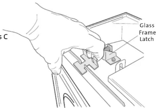
Figure 10. Pull spring latch to disengage from glass frame.
Minimum Clearances from Combustible Material to the Vent System
All pipe components must be installed according to approval and the instructions of the manufacturer. Adhere to the instructions of the manufacturer as regards clearance from to the vent system to combustible material.
When moving the chimney the clearance from combustible material to the upper side of horizontal pipe must be minimum 100 mm. The clearance from the bottom of the vent pipe to combustible material must be minimum 75 mm.
Logset Installation
Brick Kit Note: Bridda Kth Nopeional Antique Brick Kit 155370 before installing the log set. See instructions supplied with that kit. The GF 3 CF2 log set must be installed before operating the burner. The log set includes four log pieces, packaged inside the firebox, and a quantity of ceramic embers.
To install the log set, remove the packaging and place the parts inside the firebox as illustrated in the diagrams below. Do not handle the log set with your bare hands. Always wear gloves to prevent skin irritation from the ceramic fibres.
THE CERAMIC FIBRE LOGS AND EMBERS CAN IRRITATE YOUR SKIN. GENTLY WASH YOUR HANDS WITH WARM SOAPY WATER AFTER HANDLING THE LOGS OR EMBERS.
The embers realistically simulate glowing coals when the burner is operating. These should be spread evenly over the burner plate and around the logs.
- Engage the holes in the underside of the rear log with the two pegs in the burner skirt as in fig. 11.
- Locate the right log to overlap the rear log and engage with the peg as in fig. 12.
- Place the left log on the pegs as in fig. 13.
- Install middle log on the appropriate pegs shown in fig. 14.
- Position embers loosely and maintain 6mm clearance from the burner skirt edges. DO NOT OBSTRUCT THE PILOT ASSEMBLY OPENING and do not pile the embers in front of the burner skirt edges. See fig. 15.
- Lower the glass frame with the glass back into place and engage the latches.

Figure 11. Install rear log.

Figure 12. Install right log
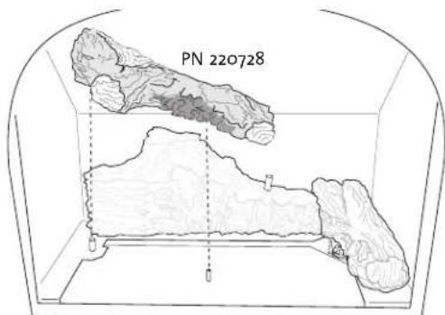
Figure 13. Install left log

Figure 14. Install middle log

Figure 15. Spread ember stones over the burner plate.
Gas Installation
Gas installation must only be performed by qualified personnel. It is important to adhere to national and local regulations that apply. In the UK these include BS5440 Pt 1&2 and BS5871 in Ireland.
The LPG gas container must be stored/installed according to national regulations. The gas container must have a pressure regulator that reduces the pressure to the required level. See technical data on page 4 for gas type and pressures before connecting to the appliance. The appliance must not be exposed to pressure above 55 mbar (5,5 kPa) during pressure testing.
Gas tubes must be made of steel (DIN 2448/1629, DIN 2458/1626, DIN 2440, DIN 2441) or copper (DIN 2110).
For practical reasons, the vent system should be installed before the appliance is connected to the gas supply.
The stove is supplied with a 3/8" to 8mm compression union. The gas valve has a 3/8" NPT threaded connection. All tube connections must be approved and the gas pipeline must have an approved shutoff valve. Only use approved sealing agent (tape) at all the pipe connections. When the pipe sections have been assembled and connected to the appliance, open the gas supply and light the appliance (see lighting instructions). Perform a tightness test on all the pipe connections.
Commissioning
Testing the Flue System
Once the appliance is fitted, gas leak and pressure tested, and the flue system complete, the flue must be checked for correct operation. This is best achieved after 10 minutes of burning by holding a smoke match just inside the downdraught diverter hood on the rear of the appliance, accessible through a cutout in the rear heatshield. The smoke should be drawn into the flue and no smoke should spill into the room. If the smoke does issue into the room, leave for another 5 minutes and retest.
The appliance is fitted with a TTB (flue sensing safety switch). If the fire does cut out automatically during flue testing, or if smoke persists to come into the room when tested, a problem is indicated within the flue system which must be thoroughly measured, checked and rectified before allowing use of the appliance.
Testing Gas Pressure
Correct gas pressure is important for the safe use of gas in the appliance. It is important that the correct gas pressure is set during the installation of the appliance. The gas valve is equipped with outlets for the testing of gas pressure. The outlets are located at the front of the valve below the ON/OFF/Pilot knob. The outlets are marked as shown in fig.16.
Outlet D: For gas pressure to the valve (volume of gas to the valve) See technical data.
Outlet E: For gas pressure from the valve (volume of gas coming out of the valve to the burner).
C: Regulator - Always test the gas pressure with the valve regulator knob on High (Hi).
Loosen the screw in the outlet and attach the tube from the manometer to the outlet. Remember to tighten the screw when the testing is completed and test for leaks at the outlets with test fluid.
Required gas pressure from the vent (Outlet E) is displayed in the table below.
GAS TYPE
MAX. / High SettingGAS TYPE
Natural gas
9.10 mbar
Propane
26.9 mbar

Figure 16. Valve pressure tap locations.
Regulating the Pilot Flame
The pilot flame should have three flames as shown in fig. 17. The two thermo-element sticks should be surrounded by two of the flames as shown in fig. 18.
The flames should be stable and the colour mainly blue. If you detect a deviation from this, turn off the pilot flame and call for service.
Adjusting the Burner
Burner adjustments must only be performed by qualified personnel. To adjust the air supply, regulate the air opening in the burner tube right above the connection of the gas supply. See fig. 19. Loosen the wingnut under the stove and adjust the air opening by pulling the air shutter to the correct opening. See fig. 20.
For Natural Gas: 9.6 mm (this dimension is preset at the factory)
For Propane: 12.6 mm (this dimension is with shutter fully open)
Note! To avoid burns, do not adjust the air shutter until the burner has cooled down.
Safety Switch
Jøtul GF 3 CF2 is equipped with a safety switch. See fig. 16, page 10. This switch stops the gas supply to the appliance if there is a blockage in the vent system. Look for obstructions in the vent system (such as bird's nests, or branches from bushes and trees). If necessary, call for service.
Annual Service
Annual service of the appliance includes the following check points.
■ Lighting the pilot flame
■ Cleaning the glass.
■ The gasket around the glass must be inspected annually for wear and replaced if necessary.
■ Check if the textured embers need to be replaced.
■ Look for soot. It could be a result of the ceramic logs not being centered in the oven and completely pushed onto the metal plate, or the air regulator has been adjusted incorrectly. (see section: Adjusting the burner)
■ Check the gas pressure if other gas equipment is connected to the gas supply.
■ Look for signs of corrosion on the appliance and the vent system.
- Look for obstructions in the vent system (such as bird's nests, or branches from bushes and trees).
Figure 17.
Proper pilot flame / carry-over port alignment.

natural_image
Simple line drawing of a robot inside a vehicle, enclosed in a circular frame (no text or symbols)Figure 18.
The thermocouple and thermopile should be fully engulfed by the pilot flames.
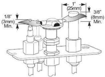

Figure 19. Air Shutter Adjustment.

Figure 20. Loosen wingnut to adjust air shutter..
User Information
General
Assembly, installation, maintenance and gas conversion (if required) must be performed by a qualified person in accordance with the instructions for assembly, Installation and use enclosed with the product. The installation may only be operated after it has been inspected by a qualified person and a certificate of completion has been issued.
The Installation should be carried out in accordance with the Building Regulations which include the following standards for installation and maintenance of flues, ventilation and installation of Gas Fires. For UK BS5440:1, BS5440:2, BS5871 for Republic of Ireland IS813, ICP3, IS327
This appliance incorporates a spillage monitoring device (TTB) this device will shutdown the appliance in the event of interruption to the evacuation of combustion products. I.e. Flue blockage.
If the appliance spillage monitoring device (TTB) shuts down the appliance repeatedly the appliance should not be used and a qualified service engineer should be called for service.
The ceramic fuel effect should only be arranged by qualified service engineer and under no circumstances should extra elements be added to the fuel effect. I.e. Extra logs or Coals
The appliance should be serviced annually by a qualified service engineer and should include attention to the appliance, installation pipe work and the inspection and cleaning if required of the flue system.
The minimum clearance to combustible material in front of the appliance is 600 mm.
Curtains may not be placed within 600mm above the appliance.
A combustible shelf may not be placed over the appliance if it is within 520mm
This appliance becomes hot in use so it advisable to keep young children, the aged or infirm and animals at a safe distance using a fireguard conforming to BS6539 or BS6778 to provide extra protection.
Operating Instructions
Lighting
Note! Odors when using the stove:
When used for the first time, the appliance may emit an irritating gas that may smell a little. The gas is not toxic, but the room should be thoroughly aired out. During first time use, it may take a little while before the gas tube is cleared of air, but subsequently the appliance should function as described in the lighting instruction. The appliance operates with the aid of a pilot flame, which is lit manually according to the lighting instruction.
Prior to lighting:
Check the area around the appliance for possible gas leaks/odors. Especially check near the floor, since propane is heavier than air and would gather close to the floor in the event of a leakage. (Note: Natural gas is lighter than air and will gather under the ceiling). If you detect an odor of gas, see warning under: Safety precautions.
Only use your hands to operate the control knobs; do not use tools. If you are unable to turn or push in the control knob, do not use force. Call for service.
Do not use the appliance if any part of it has been submerged in water. Call for service to replace the parts that have been in water.
Lighting Instructions
Lighting the Pilot Flame
The valve control knobs are located on the front of the appliance behind the control cover plate. See fig. 21. The Burner ON/OFF switch is located on the rear on the left towards the top of the appliance. See fig. 22. This switch has three settings ON/OFF/STAT the STAT position is for use of a remote control thermostat, not available at present, and this setting should not be used.
- Place the ON/OFF switch to "OFF" position. Make sure the gas valve on the pipeline to the appliance is open.
- Push in the gas control knob on the front of the valve ("B", fig. 21) a little, and turn clockwise to "OFF". Note: It is impossible to turn the gas control knob unless it is pushed in a little. Do not use force.
- Push in the gas control knob (B) a little and turn counter-clockwise to "PILOT".

Figure 21. Valve Controls.
-
Push in the gas control knob (B) as far as possible and hold it in. Simultaneously, push in the ignition knob (A) until the spark ignites the pilot flame located to the right rear corner of the burner..
-
Continue to hold in the gas control knob for approx. 20 seconds after the pilot flame has been lit. Then let go of the knob. It should pop back out and the pilot flame should remain lit.
If the pilot flame goes out, repeat Steps 1-5.
If the pilot light goes out intentionally or unintentionally, it should not be relit within 3 minutes.
*NOTE of the gas control knob does not pop out when released, call for service.
**NOTENIO the pilot flame does not remain lit after several attempts, turn the gas control knob to OFF and call for service.
Lighting the Main Burner
-
Turn the gas control knob clockwise to "ON".
-
Push the ON/OFF switch at the rear of the appliance to "ON".
NOTE: When the appliance is used for the first time, condensation may form in the firebox. Some smoke may also appear from the appliance during the initial hours, due to the burning off of paint and lubrication used in the production process. See section Odors when using the stove for the first time.
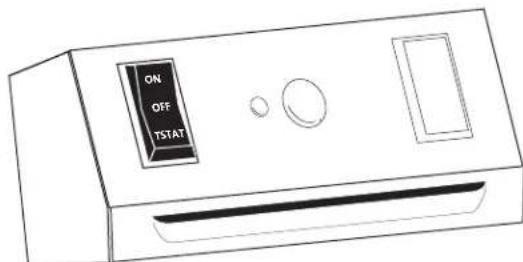
Figure 22. Burner Controls.
Adjusting the Heat Setting
Heat and flame size can be adjusted by turning the regulator knob (C) marked "HI, LOW", which is located next to the gas control knob (see fig.21). Maximum flame size provides maximum heat. Make sure the appliance has been operating for at least 30 minutes before adjusting the flame.
Turning Off the Appliance
Push the ON/OFF switch at the rear of the appliance to "OFF". The pilot flame will continue to burn. In order to fully extinguish the appliance, push in the gas control knob (C) (fig. 21) a little and turn clockwise to "OFF". Do not use force.
Maintenance
The complete installation, which includes the gas supply, the actual appliance and the vent system, must be inspected annually. The inspection must be carried out by qualified service engineer.
External Maintenance
Painted products may change color after some years of usage. The surface should be cleaned and brushed free of any loose particles before new stove paint is applied. Enameled products must only be cleaned with a dry cloth.
Do not use water or soap. Enamel surfaces stain easily when hot. Use only a soft damp cloth and only on cold surfaces.
Troubleshooting
When No Spark is Generated at the Pilot Head
It is uncommon for the Piezo spark ignitor (fig 23-A) to fail, unless it has mechanical damage. If the spark is not conducted forward, it could be the result of a break in the electrical circuit leading up to the pilot head. The spark is small or weak if there is too much resistance from a bent wire (E), or if corrosion appears at the electrode (G) or the pilot head (H). This could result in insufficient heat to light the gas. Inspect the pilot burner by looking for damage to the individual parts. Check for damaged wires or wires crushed between plate sections of the appliance and check for loose connections.
Follow the trouble-shooting procedure below when no spark is generated at the pilot head electrode:
- Make sure the spark gap between electrode (G) and pilot head (H) is smaller than or equal to 3.2 mm. If not: check if the electrode is loose or damaged
- Make sure the spark ignitor (A) is securely mounted and the ground connection is in contact with the bracket. If not: turn the spark igniter until the ground connection is in contact with the bracket and tighten the nut at the back of the spark igniter.
- Make sure the insulated wire (E) is intact and without cracks and properly connected between spark igniter (A) and electrode (G). If not: properly fasten the insulated wire to establish a connection between the spark igniter and the electrode. Replace the electrode if the wire is damaged or cracked.
- Make sure the ceramic insulation (F) is intact and without cracks If not: replace the electrode.
- Make sure a spark is generated when you dismantle the Piezo spark igniter and put the ground connector against a metal piece, and the control knob (red mark) on the spark igniter is finally pushed to the bottom (B). If not: replace the Piezo spark ignitor.

Figure 23. Pilot ignition components.
Fuel Gas
Correct gas pressure is important; see the section about gas pressure under Gas Installation, page 10. The gas pressure before the valve and the gas pressure from the valve to the main burner and pilot burner, are equally important. These parameters may be the cause of various performance problems.
If the gas pressure is too low, it can cause low pilot flame, insufficient production of electricity at thermopile and thermocouple, and poor flame pattern.
If the gas pressure is too high it can cause valve damage if the pressure rises above 60 mbar. This is usually the result of faulty installation or lack of a gas regulator on the gas tank or cylinder. High gas pressure may also cause an abnormally large pilot flame which can overheat the thermopile and thermocouple, and further cause a shutoff of the valve due to insufficient millivolt production. Problems involving high flames and soot indicate that the air volume is too small in relation to the gas volume. It is wrong to correct the problem by adjusting the air regulator, if the cause is that the gas pressure is too high. Checking the gas pressure before the valve will uncover faults in the gas supply at the valve or from the tank/cylinder.
If the gas pressure to the valve is correct, the fault must be found after the valve. A measurement performed with a manometer will help you to swiftly uncover and eliminate sources of errors. As mentioned above, blocked or poor gas supply may lead to faulty combustion. Make sure all gas tubes are dirt-free, as a small dust particle can obstruct the pilot orifice. Components must remain free of dirt during installation of the gas supply and connection to the appliance, and when the valve is being replaced.
When There is No Gas Flow To The Pilot Head
This is the trouble-shooting procedure for the gas supply: Check if all gas connections are sealed by using strong soapy water (avoid synthetic soaps). Be certain all valves from the gas tank/cylinder are fully open.
When the pilot is to be lit for the first time with a new installation, after a scheduled disconnection or after the propane tank has been refilled, there will often be air in the gas tube leading up to the appliance. The tube system must be cleared of air before the pilot burner can be lit. The recommended method for clearing air out of the tube system, is to push in the gas control knob and turn anti-clockwise to "PILOT". Then push in the gas control knob for 5 seconds and push the control knob on the spark igniter to the bottom several times. Repeat the procedure until the pilot is lit.
If the pilot does not light after attempts to clear the tube system of air, it indicates a problem with the gas tank/cylinder or a leak in the gas tube. Check the gas pressure as instructed in the section Gas Installation on page 10 and determine if the fault/leak is before or after the valve on the appliance. If the gas pressure at outlet D (fig. 21) is too low or there is no gas pressure at all, the fault or leak must be located before the valve on the appliance. If the gas pressure is OK at outlet (D), but too low at outlet (E), then the fault or leak must be located after the valve.
Note! SIT valves are always equipped with a fine filter at the inlet to avoid dirt from entering into the valve. Consequently, dirt in the valve is not a common occurrence. If gas tubes are dismantled, all gas tubes must be reinstalled and checked for gas leaks prior to operating the appliance.
When the Pilot Goes Out - Problems With the Gas Supply
This is the trouble-shooting procedure for the gas supply: Remember to push in the gas control knob for at least 30 seconds. Make sure the flame is centred at the thermocouple. Make sure the thermocouple is enveloped by the flame up to at least 3 mm (1/8") from the tip (fig. 18).
If the flame is abnormally large or small, check the gas pressure first. See section about gas pressure, page 10. Then check for errors, dirt or corrosion on the pilot burner (fig.18), the pilot orifice and the gas supply to the pilot burner.
Note! There could be a leak after the valve even if the pressure is OK at outlet E. You should therefore always check for leakage.
Thermocouple (Fig.24) and Thermopile (Fig. 25)
A thermocouple is in principle a thermal generator and consists of a copper wire (copper-nickel alloy) and an iron wire twisted together. These wires will create friction and generate 25 millivolt when exposed to a temperature difference of 200^ C. This voltage is sufficient to make the gas valve function. In order to produce higher voltage a thermopile is used, which is based on the same principle as the thermocouple, but with more copper and iron wires.
The thermopile produces approx. 500-700 millivolts. This only amounts to 1/3 of the voltage in a flashlight battery. It is important to understand that even minor resistance (ohm) will have great impact on such a small voltage. If resistance is too great, the gas valve may not receive enough voltage to operate. If there is too much resistance, the cause may be that the copper wire conducting the voltage is too long, or there are too many connections. If the copper wire comes in contact with metal, it may increase resistance and consequently reduce the voltage.
When the Pilot Goes Out, But the Gas Supply is OK.
This is the trouble-shooting procedure for the thermocouple, fig. 24,B: Check the copper wire (F) of the thermocouple for cracks or damage.
Check the gasket (C) at the valve by loosening the nut that holds the copper wire. Look for signs of damage, if the nut has been tightened too hard. A damaged gasket results in resistance at contact with metal and consequently the voltage to the valve will be too small.
Make sure the flame is centred at the thermocouple. Make sure the thermocouple is enveloped by the flame up to at least 3 mm from the tip (see fig.21). Check the voltage generated by the thermocouple. Connect the multimeter (fig.24-E) with plus to the ball point (D) at the end of the copper wire. Connect minus to the copper wire. Light the pilot (A) and hold in the control knob to prevent the flame on the pilot burner from going out. At this point the multimeter should show 14-28 mV. the thermocouple. Note that there are 2 threaded holes that can be used when installing a new thermocouple. Make sure the blue wire (A) is fastened at the same threaded hole. The nut on the thermocouple must not be tightened too much, just a 1/2 turn. If the gas pressure is correct and the possible faults above have been checked, the pilot flame can be adjusted with the adjusting screw. The gas volume is increased when the screw is turned anti-clockwise.
When There is No Gas Supply to the Burner.
This is the trouble-shooting procedure for the electrical components:
- Make sure the control knob on the valve is set to "ON". Check the position on the "ON/OFF/Thermostat" switch at the back of the appliance. It should be set to the ON position.
- Make sure the wire from the valve to the "ON/OFF/STAT" switch is connected correctly.
This is the trouble-shooting procedure for the thermopile (fig. 25):
- Make sure the gas pressure is correct (see section about gas pressure, page 10).
- Make sure the pilot burner has 3 flames.
- Make sure the flame is centred on the thermocouple.
- Make sure the thermocouple is enveloped by the flame up to at least 10mm (3/8") from the tip (fig 19).
- Check the wires to the thermopile for cracks or damage.
- Dismantle the wires from the vent.
- Dismantle optional equipment, such as thermostat or remote control.
- Check the voltage generated by the thermopile (see fig 25). Connect the multimeter with plus to one cable clip (D). Connect minus to the other cable clip. Light the pilot and make sure the control knob remains on "PILOT" (fig. 21-B). At this point the multimeter should show 500-700mV.
- Reconnect the wires to the valve and make sure only the ON/OFF/STAT switch is connected.
- Turn the control knob on the valve to "ON" and turn the ON/OFF/STAT switch to "ON". At this point the multimeter should show more than 300 mV.
- If a thermostat or remote control is to be connected, it can be done now. At this point the multimeter should show more than 175 mV.

Figure 24. Thermocouple system check.

Figure 25. Thermopile system check.
Problems With the Flame Pattern
Tall, narrow, yellow flames
These flames can soot the vent system and may be the result of insufficient oxygen supply. Check for correct air volume by measuring the opening (fig.19) at the air shutter.
Correct opening dimensions are normally:
For Propane - Open 12.6 mm (fully open)
For Natural Gas - Open 9.6 mm
Warning! To avoid burns, do not adjust the air opening until the burner has cooled down. Blocked orifice: Make sure the main orifice (fig.26) is dirt-free and that the orifice has the appropriate size. See technical data.
Poor draught in the vent system may be due to improper installation or because the vent has no climb towards the chimney.
Tall, blue flames
The cause may be too much oxygen. Check for correct air volume by measuring the opening (fig. 19) at the air shutter. The cause may also be that the gas pressure is too high. Check the gas pressure as described in the section about gas pressure on page 10.
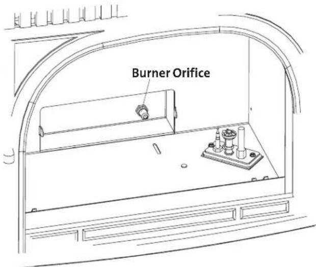
Figure 26. Check main burner orifice for debris blockage. Burner pan is removed.

Jøtul GF 3 CF 2 Parts List
| Cast Iron Parts | Matte Black | Blue Black Enamel | Ivory Enamel | Brown Majolica Enamel | Blue Majolica Enamel | |
| 1. | Side Plate | 10203292 | 102033 | 10203229 | 10203247 | 10203248 |
| 2. | Base Plate | 10390092 | 10390027 | 10390029 | 10390047 | 10390048 |
| 3. | Legs, (4) | 10192592 | 101966 | 102251 | 10192547 | 10192548 |
| 4. | Front Panel | 10390192 | 110390127 | 10390129 | 10390147 | 10390148 |
| 5. | Right Door | 10390492 | 10390427 | 10390429 | 10390447 | 10390448 |
| 6. | Top Plate | 10390292 | 10390227 | 10390229 | 10390247 | 10390248 |
| 7. | Left Door | 10390392 | 10390327 | 10390329 | 10390347 | 10390348 |
- Side Clip 128401
- Bolt, M6 x 12 mm (Side to Base).... 117130
- Bolt, M6 x 25 mm (Side to Front) 128401
- Rating Data Plate, CE 222522
- Lanyard, Rating Plate 129159
- Rivet, 1/8" 117946
- Spill Switch 220916
- Screw, 7 x 1/2" phillips (2) 118015
- Switch Box 220765
- Screw, #8 x 1/2" slotted hex 117917
- Rocker Switch, On / Off / Stat 129156
- Bolt, M6 x 20 (Front to Base) 117117
- Nut, M6 Flange 117968
- Bolt, M6 x 20 mm (Leg to Base, 4) 117117
- Washer, M6 Fender 120004
- Ignitor 3902573
- Screw, M4 x 8 phillips 117920
- Ignitor Bracket 3902576
- Gas Valve, NG - 50% TD 220520
- Nut, M6 Flange 117968
- Screw, 10-32 x 3/8 phillips (4) 117911
- Valve Bracket (2) 220721
- Screw, M4 x 12 phillips (2) 117921
- Terminal Block, 3 Pole 118028
- Terminal Block Bracket 220983
- Nut, M4 117922
- Screw, 10-32 x 3/8" phillips (2) 117911
- 8mm x 3/8" Adaptor 220168
- Compression Sleeve (2) 129463
- Compression Nut (2) 129464
- Main Gas Flex Tube, 5/16" 129462
- Jam Nut 129152
- Orifice Holder 220643
- Burner Orifice, NG G20 -2.35 129801
Burner Orifice, LP G31 - 1.40 129804 - Wing Nut, M6 117975
- Washer, 2 1/4" O.D. 118023
- Gasket, 2 1/4" O.D. 220734
- Air Shutter 220791
- Bolt, M6 x 20 (Tube Holder to Burner) ..... 117117
- Tube Holder, Cast Iron 103992
- Venturi Tube 220631
- Burner Base, Cast Iron 103991
- Burner Gasket 220633
Burner Asby, Complete 155336 - Burner Plate, Stainless Steel 220545
- Burner Skirt 220766
- Pilot Gasket 129670
- Pilot Spacer 220546
- Pilot Assembly, NG 129471
Thermopile 3094527
Thermocouple 129766
Ignitor 3902573 - Screw, #8 x 3/4" sheet metal (2) 117986
- Glass, Ceramic 220576
-
Bolt, M6 x 10 mm, Flange 9962
-
Door Clip 122009
- Door Hinge Pin (4) 125960
- Glass Frame 22252492
- Glass Gasket, Tadpole 129124
Replacement Glass Kit 155599 - Firebox, Heat Exchanger 221192
- Screw, #8 x 1/2" Blk 117917
- Nut, M6 Flange (2) 117968
- Exhaust Baffle 220763
- Inner Draft Hood 220914
- Screw, #8 x 1/2" Blk (4) 117917
- Upper Draft Hood 222519
- Draft Hood Cover Plate 222520
- Starter Collar, 5" dia. 222514
- Screw, #8 1/2" Blk (4) 117917
- Glass Frame Latch 129135
- Screw, #8 1/2" Blk (4) 117917
- Heat Exchanger Fins, (2) 155653
- Nut, M6 Flange (2) 117968
- Controls Heat Shield, (2) 220918
- Rear Shroud 220764
- Right Log 220729
- Middle Log 220730
- Rear Log 220727
- Left Log 220728
- Screw, #8 x 1/2" Blk (4) 117917
- Control Door 221187
- Air Deflector, Lower Rear 220979
- Wire Harness Assembly 155604
- Air Deflector, Top 220978
- Hinge Bolt, M6 x 130 mm Hex Hd ..... 118033
- Fender Washer .250 x 1.500dia. 118029
- Spacer, .375 o.d. x 3.172 118040
- Spacer, .375 o.d x .172 118039
- Ember Stones, 4 oz. * (included in Logset)...... 220702
- *Orifice Retainer 221367
*not illustrated
Accessories
Antique Brick Panel Kit 155648
Fuel Conversion Kit to Propane / G31 156472
Fuel Conversion Kit to Natural Gas / G20 ..... 155473
Screen 129174
This appliance must be installed in conformance with local and national building regulations. Before beginning the installation, it is important that the these instructions be carefully read and understood. Jøtul maintains a policy of continual product development. Consequently, products may differ in specification, color or type of accessories from those illustrated or described in various publications.
Unit 1, The IO Centre, Nash Road
Park Farm North, Redditch,
Worestershire, UK B98 7AS
Tel:01527 501610 Fax:01257 528181
www.jotuluk.com
- Installation and Operation Instructions
- Jøtul GF 3 CF 2
- INSTALLATION SIGNATURE FORM
- Table of Contents
- Jøtul GF 3 CF 2 Technical Information
- General Information
- Safety Precautions
- Installer Information
- WARNING:
- Installation Guide for Qualified Personnel
- Fixing
- Requirements for Floor Plate
- Firewall Requirements
- Position of Appliance
- Flue System Installation
- Closure Plate Installation
- Assembly Prior To Installation
- Minimum Clearances from Combustible Material to the Vent System
- Logset Installation
- Gas Installation
- Commissioning
- Testing the Flue System
- Testing Gas Pressure
- Regulating the Pilot Flame
- Adjusting the Burner
- Safety Switch
- Annual Service
- User Information
- General
- Operating Instructions
- Lighting
- Note! Odors when using the stove:
- Prior to lighting:
- Lighting Instructions
- Lighting the Pilot Flame
- Lighting the Main Burner
- Adjusting the Heat Setting
- Turning Off the Appliance
- Maintenance
- External Maintenance
- Troubleshooting
- When No Spark is Generated at the Pilot Head
- Fuel Gas
- When There is No Gas Flow To The Pilot Head
- When the Pilot Goes Out - Problems With the Gas Supply
- Thermocouple (Fig.24) and Thermopile (Fig. 25)
- When the Pilot Goes Out, But the Gas Supply is OK.
- When There is No Gas Supply to the Burner.
- Problems With the Flame Pattern
- Tall, narrow, yellow flames
- Tall, blue flames
- Accessories
Brand : JOTUL
Model : GF 3
Category : Heating