
DiVA A70 - Receiver ARCAM - Free user manual and instructions
Find the device manual for free DiVA A70 ARCAM in PDF.


| Product Type | Stereo Integrated Amplifier / Receiver |
| Brand | Arcam |
| Model | DiVA A70 |
| Power Output | 60 watts per channel into 8 ohms |
| Dimensions (W x H x D) | 430 x 105 x 375 mm (16.9 x 4.1 x 14.8 in) |
| Weight | 11 kg (24.3 lbs) |
| Power Consumption | 250 W (max), <0.5 W standby |
| Inputs | 6 line-level (RCA), 1 phono (MM), 1 tape loop, 1 power amp input |
| Outputs | 2 preamp outputs, 1 tape record, 1 subwoofer, speaker terminals (A/B) |
| Frequency Response | 20 Hz – 20 kHz ±0.1 dB |
| Total Harmonic Distortion | <0.005% at 1 kHz, 60W 8 ohms |
| Signal-to-Noise Ratio | >100 dB (line input, A-weighted) |
| Input Sensitivity | 250 mV (line), 2.5 mV (phono MM) |
| Damping Factor | >200 |
| Remote Control | CR-80 or compatible learning remote |
| Headphone Output | 6.35 mm jack, suitable for 32-600 ohm headphones |
| Speaker Impedance | 4 – 16 ohms (4 ohms with care) |
| Protection | Overload, short circuit, DC offset, thermal protection |
| Power Supply | AC 220-240V, 50/60 Hz (adjustable via internal voltage selector) |
| Cleaning | Use a soft, dry cloth. Do not use solvents or abrasive cleaners. |
| Maintenance | Only qualified personnel should service internal components. No user-serviceable parts inside. |
| Repairability | Replaceable input selectors, protection relay, and fuse. Consult a certified technician for repairs. |
Frequently Asked Questions - DiVA A70 ARCAM
User questions about DiVA A70 ARCAM
0 question about this device. Answer the ones you know or ask your own.
Ask a new question about this device
Download the instructions for your Receiver in PDF format for free! Find your manual DiVA A70 - ARCAM and take your electronic device back in hand. On this page are published all the documents necessary for the use of your device. DiVA A70 by ARCAM.
USER MANUAL DiVA A70 ARCAM
CAUTION: To reduce the risk of electric shock, do not remove cover (or back). No user serviceable parts inside. Refer servicing to qualified service personnel.
WARNING: To reduce the risk of fire or electric shock, do not expose this apparatus to rain or moisture.
The lightning flash with an arrowhead symbol within an equilateral triangle, is intended to alert the user to the presence of uninsulated 'dangerous voltage' within the product's enclosure that may be of sufficient magnitude to constitute a risk of electric shock to persons. The exclamation point within an equilateral triangle is intended to alert the user to the presence of important operating and maintenance (servicing) instructions in the literature accompanying the product.
CAUTION: In Canada and the USA, to prevent electric shock, match the wide blade of the plug to the wide slot in the socket and insert the plug fully into the socket.
Important safety instructions
This product is designed and manufactured to meet strict quality and safety standards. However, you should be aware of the following installation and operation precautions:
1. Take heed of warnings and instructions
You should read all the safety and operating instructions before operating this appliance. Retain this handbook for future reference and adhere to all warnings in the handbook or on the appliance.
2. Water and moisture
The presence of electricity near water can be dangerous. Do not use the appliance near water – for example next to a bathtub, washbowl, kitchen sink, in a wet basement or near a swimming pool, etc.
3. Object or liquid entry
Take care that objects do not fall and liquids are not spilled into the enclosure through any openings. Liquid filled objects such as vases should not be placed on the equipment.
4. Ventilation
Do not place the equipment on a bed, sofa, rug or similar soft surface, or in an enclosed bookcase or cabinet, since ventilation may be impeded. The unit should be installed in a well-ventilated area.
5. Heat
Locate the appliance away from naked flames or heat producing equipment such as radiators, stoves or other appliances (including other amplifiers) that produce heat.
6. Climate
The appliance has been designed for use in moderate climates.
7. Racks and stands
Only use a rack or stand that is recommended for use with audio equipment. If the equipment is on a portable rack it should be moved with great care, to avoid overturning the combination.
8. Cleaning
Unplug the unit from the mains supply before cleaning.
The case should normally only require a wipe with a soft, damp, lint-free cloth. Do not use paint thinners or other chemical solvents for cleaning.
We do not advise the use of furniture cleaning sprays or polishes as they can cause indelible white marks if the unit is subsequently wiped with a damp cloth.
9. Power sources
Only connect the appliance to a power supply of the type described in the operating instructions or as marked on the appliance.
Warning: This is a Class I device and must be earthed.
Warning: The mains plug is used as the disconnect device from the mains supply and shall remain readily operable.
10. Power-cord protection
Power supply cords should be routed so that they are not likely to be walked on or pinched by items placed upon or against them, paying particular attention to cords and plugs, and the point where they exit from the appliance.
11. Grounding
Ensure that the grounding means of the appliance is not defeated.
12. Power lines
Locate any outdoor antenna/aerial away from power lines.
13. Non-use periods
If the unit has a stand-by function, a small amount of current will continue to flow into the equipment in this mode. Unplug the power cord of the appliance from the outlet if left unused for a long period of time.
14. Abnormal smell
If an abnormal smell or smoke is detected from the appliance, turn the power off immediately and unplug the unit from the wall outlet. Contact your dealer immediately.
15. Servicing
You should not attempt to service the appliance beyond that described in this handbook. All other servicing should be referred to qualified service personnel.
16. Damage requiring service
The appliance should be serviced by qualified service personnel when:
A. the power-supply cord or the plug has been damaged, or
B. objects have fallen, or liquid has spilled into the appliance, or
C. the appliance has been exposed to rain, or
D. the appliance does not appear to operate normally or exhibits a marked change in performance, or
E. the appliance has been dropped or the enclosure damaged.
17. Speaker connections
Any speakers must be connected to the A70 using Class 2 wire (i.e., no connection to earth should be made). Failure to observe this precaution may cause the unit to be damaged.
Safety compliance
This product has been designed to meet the IEC 60065 international electrical safety standard.
Using this handbook
This handbook has been designed to give you all the information you need to install, connect, set up and use the Arcam A70 amplifier. The CR-389 remote control handset supplied with the A70 amplifier is also described.
Your amplifier may have been installed and set up by an authorised Arcam dealer. In this case, you may wish to go directly to the sections describing the use of this equipment.
Safety
Safety guidelines are set out on the inside front cover of this handbook.
Many of these items are common sense precautions, but for your own safety, and to ensure that you do not damage the unit, we strongly recommend that you read them.
Contents
Safety guidelines ......E-2
Important safety instructions ....E-2
Safety compliance....E-2
Using this handbook ....E-3
Safety E-3
Installation ......E-4
Positioning the unit ......E-4
Connecting to loudspeakers .....E-4
Connecting to a power supply ......E-4
Connecting to other equipment ....E-5
Using your A70 amplifier ....E-6
Front panel controls ......E-6
Recording ......E-7
Setting up your A70 amplifier ....E-8
Using the remote control ......E-9
CR-389 Remote Control E-9
Bi-wiring and bi-amping loudspeakers ....E-10
Before you start E-10
Bi-wiring your loudspeakers E-10
Bi-amping your system E-10
Service information ......E-11
Sound cuts out unexpectedly E-11
Technical specifications ....E-11
Remote-control codes ......E-12
Guarantee ......E-12
Worldwide Guarantee E-12
On-line registration E-12
Installation
Positioning the unit
Place your amplifier on a level, firm surface. Avoid placing the unit in direct sunlight or near sources of heat or damp.
Ensure adequate ventilation. Do not place the unit in an enclosed space such as a bookcase or cabinet as both of these will impede air flow through the ventilation slots.
Connecting to loudspeakers
You can connect one or two pairs of loudspeakers to your amplifier, provided each pair is rated between 8–16Ω. If one or both pairs have an impedance of less than 8Ω, the combined load on the amplifier falls below 4Ω and could cause an overload. If so, the overload protection circuit may engage and the amplifier will not work.
To connect one pair of loudspeakers, use the SP1 terminals.
Caution: Do not over tighten the loudspeaker terminals or use a wrench, pliers, etc., as this could cause damage to the terminals which will not be covered under warranty.
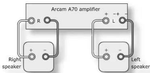
Wiring your loudspeakers
SP1 and SP2 terminals 4
Both sets of loudspeaker terminals can be muted by pressing the MUTE button on the remote control. To switch SP1 and SP2 independently, use the front panel switches (see page 6,②) or the remote control (see page 9).
Your amplifier is fitted with industry standard loudspeaker terminals. The terminal accepts spade terminals or bare wires.
To connect a spade terminal or bare wire, unscrew the red (or black) part of the loudspeaker terminal first. Insert the wire or spade terminal and screw it back up.
Connect the right speaker to the terminals on the back of your amplifier marked R and the left speaker to the terminals marked L.
Connect your loudspeakers so that the red (positive/+) terminal on each loudspeaker is connected to the red (positive/+) terminal on the amplifier. Your loudspeaker cables may be marked to show polarity (negative/- and positive/+), if not, then the positive terminal can usually be identified by a ridge or coloured marking.
Now connect your loudspeakers' black (negative/−) terminals to the black (negative/−) terminals on the amplifier. Ensure that no stray strands of inner wires are allowed to touch another cable or the amplifier's casing. This can cause a short circuit and damage your amplifier!
Connecting to a power supply
Mains lead
The appliance is normally supplied with a moulded mains plug already fitted to the lead. If for any reason the plug needs to be removed, it must be disposed of immediately and securely, as it is a potential shock hazard when inserted into the mains socket. Should you require a new mains lead, contact your Arcam dealer.
Wrong plug?
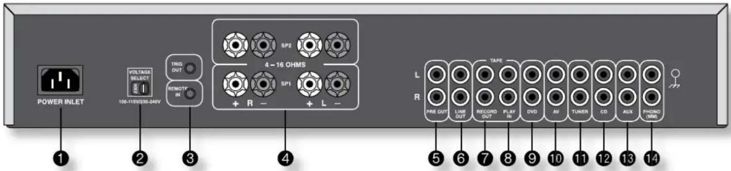
Check that the plug supplied with the unit fits your supply and that your mains supply voltage agrees with the voltage setting (115V or 230V) indicated on the rear panel of the unit ② before plugging in.
If your mains supply voltage or mains plug is different, consult your Arcam dealer or Arcam Customer Support on +44 (0)1223 203200.
The product must be earthed.
Plugging in
Push the plug (IEC line socket) of the power cable supplied with the unit into the socket (POWER INLET) ① in the back of the unit. Make sure it is pushed in firmly.
Put the plug on the other end of the cable into your power supply socket and switch the socket on.
Standby power
For remote standby operation, the amplifier's control power supply is kept powered up all the time the unit is connected to the mains supply. The front panel power switch powers down all other circuitry. Power consumption in this mode is less than 2.5W.
This means that even though the power switch is off, it may be possible to hear a slight hum coming from the mains transformer inside the amplifier. This is perfectly normal. If the unit is to be left unused for an extended period, we recommend that it is disconnected from the mains supply by switching it off at the wall socket, or by disconnecting the power lead.
Connecting to other equipment
The use of high quality interconnect cables to and from your amplifier is recommended to ensure the best sound quality. Sockets marked L (and R) on your amplifier should only be connected to sockets marked L (and R) on other equipment. All the line inputs have the same sensitivity and may be used with equipment other than that labelled, if needed.
LINE OUT ⑥ – Connect this output to the audio inputs of any unit with a line-level input, e.g., tape deck, etc.
TAPE/ RECORD OUT ⑦ – Connect these output sockets to the input sockets of your cassette deck (usually labelled RECORD).
TAPE/ PLAY IN ⑧ – Connect these input sockets to the output sockets of your cassette deck (usually labelled PLAY). If you do not have a cassette deck you can use this input for other (line level) equipment, such as a CD player, tuner, VCR, etc., but not a turntable.
DVD ⑨ – Connect this input to the audio outputs of a DVD player.
AV 10 - Connect this input to the audio outputs of audiovisual equipment such as a VCR, laserdisc player, satellite or Nicam tuner.
TUNER 11 - Connect this input to the audio outputs of your radio tuner.
CD 12 - Connect this input to the audio outputs of your CD player or DAC (digital to analogue converter).
AUX 13 - Connect this input to the audio outputs of any unit with a line level output, e.g. tape deck, tuner, etc.
PHONO 14 - Connect this input to the output of your record player. This input provides RIAA equalization and is compatible with most high output moving magnet (MM) cartridges.
Phono earth terminal – For connecting your turntable earth lead (if fitted). Note that this terminal must not be used as a safety earth.
TRIG OUT and REMOTE IN ③ (12V in and out) – Each socket accepts a 3.5mm Mono Jack, with Tip=signal, Sleeve=ground. The connections are intended for use in multi-room installations.
TRIG OUT – This output provides a 12V signal whenever the unit is switched on (i.e., not off or in standby). This signal can be used to switch on automatically power amplifiers (or other equipment) connected to the A70, as they will come on when the A70 is activated. This is useful if the power amplifier is remote from the A70, or otherwise difficult to access. If you are bi-amping with a power amplifier and wish to power both units on or off simultaneously, see page 10.
REMOTE IN – This allows remote control signals to be received by the A70 if the remote sensor is covered (or otherwise not 'visible' to the remote control). An external sensor is used to receive the signals from the remote control, which are then fed to the A70 (into this input) using a suitable cable. Remote control signals acceptable to the A70 must be in modulated RC5 format, with a voltage level of between 5V and 15V.
Note that in normal use there is no need to make any connections to these sockets. If you would like to make use of these features, please contact your dealer for more advice on how to make the connections and on what type of cable to use.
Pre/ power amplifier connections
If you wish to use your A70 as a power amplifier, please consult your Arcam dealer.
PRE OUT ⑤ – To use your amplifier as a pre-amplifier, connect the PRE OUT sockets to the input sockets of your power amplifier. With a power amplifier of the correct gain (e.g. an Arcam P90 power amplifier) you can bi-amplify ('bi-amp') suitable loudspeakers, giving significant improvements in sound quality (see page 10).
The different output types
The distinction between PRE OUT, LINE OUT and RECORD OUT output types is subtle but important.
PRE OUT: This is the output that should be connected to your power amplifier. The output level varies with the volume control.
LINE OUT: This output is taken before the volume control, i.e., the source being listened to is routed directly to this output. If you wish, this output may be connected to a recording device, such as a cassette recorder. Under no circumstances should this output be connected to a power amplifier.
RECORD OUT: The output from the RECORD OUT connectors is dependent on the configuration of the amplifier. Full instructions for this output are given on page 7; briefly, if the amplifier is configured to 'REC SOURCE', then this output will carry the same signal as the LINE OUT connection. If the amplifier is configured so that you are recording a different source than the one you are listening to, then the RECORD OUT connections will carry the source being recorded.
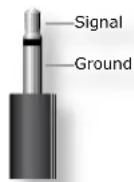
3.5mm Mono Jack
Using your A70 amplifier
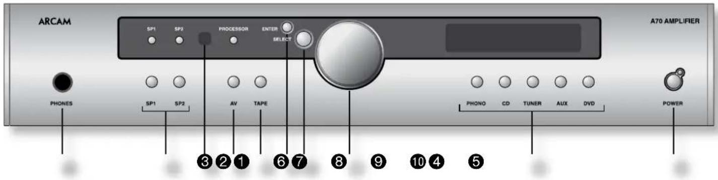
Front panel controls
This section describes how to operate your amplifier.
If you are installing the amplifier yourself, you should first read the 'Installation' section on page 4.
POWER (and power indicator light) 10
Switches the unit on and off. (You can also switch the amplifier into standby mode with the remote control handset.)
The light indicates the status of the amplifier. A red light means the amplifier is in standby mode (press the POWER/ STANDBY button on the remote control, or the POWER button on the front panel, to switch between standby and powered-up modes).
When you switch your amplifier on, the light glows amber for a few seconds, during which time the speakers are disconnected. The light changes to green when the amplifier is ready for use.
The light may flash if a fault has occurred – the fault type is shown on the display. You should unplug the amplifier and leave it for a few minutes before reconnecting. If the fault cannot be cleared, unplug your amplifier and contact your Arcam dealer.
Source selectors ⑨
These buttons select the source connected to the corresponding input. The input currently selected is indicated by text on the display.
AV 4
This input is similar to the other line level inputs on the amplifier and may be used with a VCR or a second recording unit (e.g. cassette deck).
Control knob, SELECT and ENTER ⑧⑦⑥
The control knob has two functions:
as a volume control, to adjust the output of loudspeakers and headphones connected to the amplifier, and of the pre-amp output (PRE OUT).
■ when used in conjunction with the SELECT and ENTER buttons, to customise amplifier settings (see page 8).
Volume control settings
It is important to realise that the position of the Control knob is not an accurate indication of the power delivered to your loudspeakers. The amplifier often delivers its full power before the volume control reaches its maximum position, particularly when listening to heavily recorded compact discs. However the amplifier also has to be capable of giving full power output from much lower level sources, such as tuners and cassette decks. Using these sources, the volume control setting may be much higher before distortion (audible overload) sets in. To compensate for this, the input levels of each source may be individually adjusted to avoid accidental overload (see page 8).
SP1 and SP2 ②
These buttons allow you to select and deselect the main (SP1) and secondary (SP2) set of speakers attached to your amplifier.
The light above each button glows if the corresponding speakers are currently selected. If both lights are out the amplifier will appear not to work, as all speakers are switched off!
PHONES 1
This socket accepts headphones with an impedance rating between 8Ω and 2kΩ, fitted with a 1/4-inch stereo jack plug. If you wish to listen on headphones only, use the SP1 and SP2 buttons (if necessary) to mute the speakers. The headphone socket is always active.
Remote control receiver ③
The remote control's infrared receiver is positioned between the SP1/SP2 and PROCESSOR indicator lights on the left-hand side of the front panel window. Ensure the receiver is in a clear line of sight from the remote control to allow signals to be received.
Recording
With the Arcam A70 it is possible to listen and to record from one source, or to listen to one source while recording another.
The record signal is sent to the TAPE output sockets. These sockets are suitable for use with almost any type of recorder (cassette, CDR, MD, VCR, reel-to-reel, etc.).
To record the currently selected source, press the SELECT button to enter the menu system. Rotate the Control knob clockwise until the display shows REC OUTPUT. Press SELECT, REC is displayed, followed by the current setting. Rotate the Control knob counter-clockwise until REC SOURCE is displayed. After a few seconds, the display reverts to showing the volume level and you are ready to record.
To listen to one source whilst recording another, press the SELECT button to enter the menu system. Rotate the Control knob clockwise until the display shows 'REC OUTPUT'. Press SELECT. 'REC' is displayed, followed by the current setting (for example, 'REC TUNER'). Rotate the Control knob until the desired source is displayed. After a few seconds the display reverts to showing the volume level and you are ready to record.
The unit now sends the selected source ('Tuner' in the example above) to the TAPE OUT sockets while you listen to the same or an alternative source.
TAPE button operation ⑤
To play back the recording from a cassette deck attached to the TAPE input, press TAPE. ^TP- followed by a two-letter abbreviation of the record out source is shown on the display (e.g. ^TP-CD ). Selecting this input overrides the other source selectors.
If the current record out is set to REC SOURCE then the previous selected source is shown on the display. Pressing different source buttons on the front panel only changes the record output.
Tape mode can be exited by pressing TAPE again.
It is also possible to monitor a recording while it is being made, provided your cassette deck is a 3-head type. To do this, press TAPE. Switching this button in/out allows an A/B comparison between the source signal and the recorded signal.
Setting up your A70 amplifier
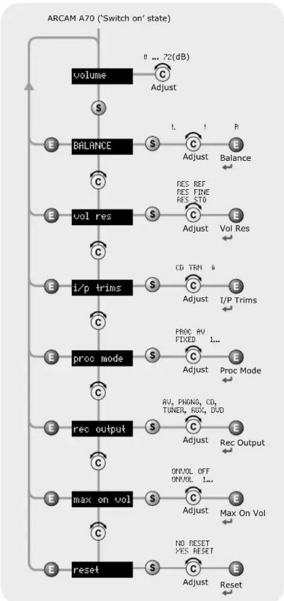
The A70 allows you to adjust listening settings to suit your taste, and to customise various features of the amplifier to fit your system. Use this diagram to help you navigate through the settings available. The ENTER and SELECT buttons are represented in the diagram by the symbols E and S respectively. The Control knob is shown as C.
Adjusting listening settings
The default display mode is VOLUME, where the Control knob is used to adjust sound level. Press SELECT to enter edit mode and cycle through the other settings: BALANCE, VOL RES, I/P trims, etc. When a setting is selected, press SELECT again and adjust it with the control knob. Press ENTER to fix the change you have made and return to idle (volume) mode.
flowchart
graph TD
    A["volume"] --> B["S"]
    B --> C["Balance"]
    C --> D["E"]
    D --> E["vol res"]
    E --> F["i/p trims"]
    F --> G["proc mode"]
    G --> H["rec output"]
    H --> I["max on vol"]
    I --> J["reset"]

    subgraph Stage1
        K["Adjust"] --> L["L"]
        M["Adjust"] --> N["I"]
        O["Adjust"] --> P["P"]
        Q["Adjust"] --> R["E"]
        S["Adjust"] --> T["E"]
        U["Adjust"] --> V["E"]
        W["Adjust"] --> X["E"]
        Y["Adjust"] --> Z["E"]
    end

    subgraph Stage2
        AA["Adjust"] --> AB["L"]
        AC["Adjust"] --> AD["I"]
        AE["Adjust"] --> AF["P"]
        AG["Adjust"] --> AH["E"]
        AI["Adjust"] --> AJ["E"]
        AK["Adjust"] --> AL["E"]
        AM["Adjust"] --> AN["E"]
        AO["Adjust"] --> AP["E"]
        AQ["Adjust"] --> AR["E"]
        AS["Adjust"] --> AT["E"]
        AU["Adjust"] --> AV["E"]
        AW["Adjust"] --> AX["E"]
        AY["Adjust"] --> AZ["E"]
        BA["Adjust"] --> BB["E"]
        BC["Adjust"] --> BD["E"]
        BE["Adjust"] --> BF["E"]
        BG["Adjust"] --> BH["E"]
        BI["Adjust"] --> BJ["E"]
        BK["Adjust"] --> BL["E"]
    end

    subgraph Stage3
        BM["Adjust"] --> BN["L"]
        BO["Adjust"] --> BP["I"]
        BQ["Adjust"] --> BR["P"]
        BS["Adjust"] --> BT["E"]
        BU["Adjust"] --> BV["E"]
        BW["Adjust"] --> BX["E"]
        BY["Adjust"] --> BZ["E"]
        CA["Adjust"] --> CB["E"]
        CC["Adjust"] --> CD["E"]
        DD["Adjust"] --> DE["E"]
        DF["Adjust"] --> DG["E"]
        DH["Adjust"] --> DI["E"]
        DJ["Adjust"] --> DK["E"]
        DL["Adjust"] --> DN["E"]
        DO["Adjust"] --> DOB["E"]
        DQ["Adjust"] --> DQB["E"]
        DQB --> DQB
    end

    subgraph Stage4
        DO["Adjust"] --> DQ["CD TRN 0"]
        DQ --> DQB["1/P Trims"]
        DQB --> DQB
    end

    subgraph Stage5
        DQB --> DQB
    end

    note1["O ... 72(dB)"]
    note2["Balance"]
    note3["vol res"]
    note4["i/p trims"]
    note5["proc mode"]
    note6["rec output"]
    note7["max on vol"]
    note8["reset"]
    note9["AV, PHONO, CD, TUNER, AUX, DVD"]
    note10["ONVOL OFF ONVOL 1..."]
    note11["NO RESET YES RESET"]
    note12["Max On Vol"]
    note13["Reset"]
Balance – Once selected, use the Control knob to shift the balance between Left and Right channels.
Volume Resolution – RES REF, RES FINE or RES STD. 'Fine' and 'Standard' represent different levels of volume control sensitivity. The 'Reference' setting gives absolute increments in 0.5dB steps.
Input Trims – use the source select buttons and Control knob to set input trims for each source. Input trims are used to compensate for variations in output levels of different source equipment.
Processor Mode – This mode enables you to adjust the gain of the amplifier. The amplifier can then be used to drive the front left and right speakers in a surround sound system when fed from a separate processor. You can then control the volume of the entire system using the processor, feeding the sound into the TAPE input. Set the gain to match the amplifiers that drive your other loudspeakers.
Recording Output – This allows you to select the source signal for recording: AU, PHONO, CD, TUNER, AUX or DUD.
Maximum 'On' Volume - Use the Control knob to adjust the volume setting at switch-on. ONVOL OFF indicates that the feature is not activated. ONVOL 1 (or higher) sets the volume at start-up (in dB).
Reset – this restores all amplifier settings, including input trims, to their factory defaults.
Using the remote control
CR-389 Remote Control
The CR-389 remote control gives access to all functions available on the front panel of the A70. It also has controls to operate Arcam CD players, AM/FM tuners and DAB tuners. The remote control transmits Philips RC-5 type codes.
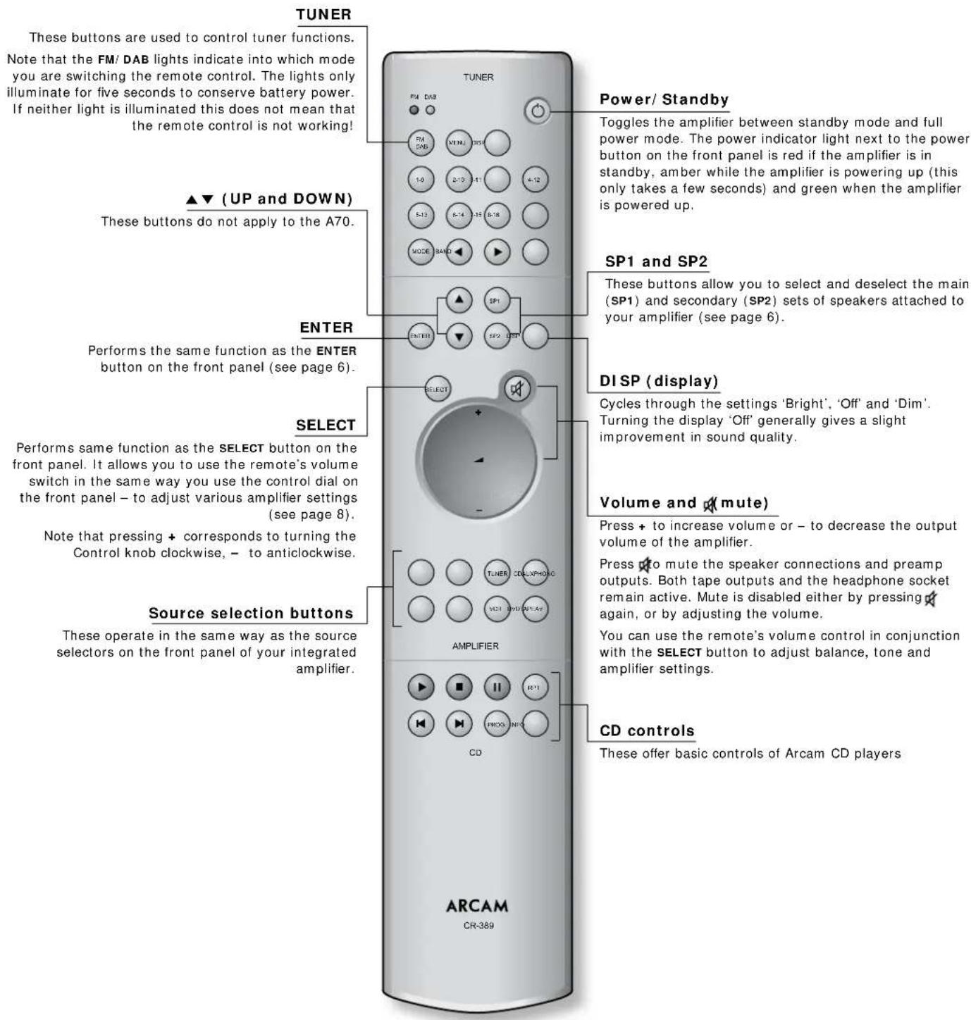
NOTE: Remember to install the two supplied AAA batteries before trying to use your remote control! Do not place anything in front of the IR receiver on the left of the A70, or the remote control may not work.
Bi-wiring and bi-amping loudspeakers
Before you start
WARNING: Do not make any connections to your amplifier while it is switched on or connected to the mains supply.
Before switching on please check all connections thoroughly, making sure bare wires or cables are not touching the amplifier chassis (which could cause short circuits) and you have connected positive (+) to positive and negative (-) to negative.
Always ensure that the volume control on your amplifier is set to minimum before starting these procedures.
Bi-wiring your loudspeakers
Bi-wiring improves the sound of your system because it divides the high and low frequency signal currents into separate speaker cables. This avoids signal distortions arising from the high and low frequency currents interacting with one another within a single cable, as in conventionally wired systems.
You will need:
Speakers – with four input terminals each: these will be marked HF (High Frequency) and LF (Low Frequency).
Loudspeaker cables – two pairs of cables per loudspeaker (which may be joined at the amplifier end if your amplifier has only one pair of output terminals per channel), or a suitably terminated cable set (a loom, probably prepared by your dealer and capable of being used for bi-amping in one length).
How to bi-wire loudspeakers
- Remove the terminal links on the rear of your loudspeakers
WARNING: This step is essential or damage to your amplifier may result which is not covered under warranty.
- Connect the cables as shown in the diagram below, ensuring correct polarity at all times.
Bi-amping your system
The performance of your system can be further enhanced over that achieved with bi-wiring, by extending the principle one stage further to include separate amplification for the low and high frequency drive units in each loudspeaker enclosure.
Connect the integrated amplifier to the high frequency (HF) terminals and connect the power amplifier to the low frequency (LF) terminals.
You will need:
Speakers – with four input terminals each (as with bi-wiring): these will be marked HF (High Frequency) and LF (Low Frequency).
Two amplifiers – one of these would be the A70 and the other an Arcam power amplifier (e.g. P90).
Loudspeaker cables – two pairs of cables per loudspeaker or a suitably terminated cable set (a loom, probably prepared by your dealer and capable of being used for bi-amping in one length).
Interconnect cables – one pair of high quality interconnect cables.
How to set up a bi-amped system
- Remove the terminal links on the rear of your loudspeakers.
WARNING: This step is essential or damage to your amplifier may result which is not covered under warranty.
-
Connect the cables as shown in the diagram below, ensuring correct polarity at all times.
-
Use the interconnect cables to connect the PRE OUT sockets of the A70 to the corresponding AUDIO IN sockets of the power amplifier.
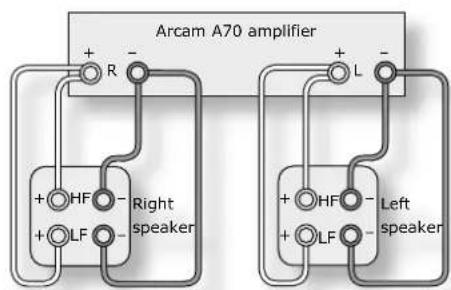
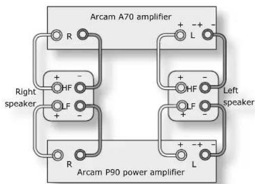
Bi-wiring using one set of connections on amplifier Recommended bi-amping configuration
Service information
Sound cuts out unexpectedly
Before returning an amplifier for repair, please check the following:
Heatsink protection
If the temperature of the internal heatsink rises above a safe level, a thermal cutout inside the amplifier operates, the power indicator on the front panel flashes and the protection system temporarily removes power to the speakers. The system resets after the heatsink has cooled down. Note that because of the high output voltage from a CD player, it is possible to drive the A70 at full power even though the volume is not set at maximum.
Transformer protection
The transformer is separately protected against thermal overload damage which may occur in exceptional circumstances. If the unit shuts down in this way, there is no indicator warning on the front panel: we recommend you disconnect the power supply and wait 30 minutes for the amplifier to completely cool. Power on in the normal way and the A70 will work normally.
Amplifier does not switch back on
The A70 and P90 amplifiers have a protection mechanism which is activated if you switch the unit on immediately after turning it off. If this mechanism activates, wait 30 seconds before switching back on again.
Technical specifications
| Continuous power output, per channel | |
| Both channels, 8Ω, 20Hz–20kHz 50W | |
| Distortion, 8Ω, 80% power, 1kHz 0.005% | |
| Inputs | |
| Phono cartridge input sensitivity, MM 2.7mV | |
| Line and tape inputs: | |
| Nominal sensitivity | 250mV |
| Input impedance | 22kΩ |
| Signal/noise ratio (CCIR) | 98dB |
| Preamplifier outputs | |
| Nominal output level 545mV | |
| Output impedance <50Ω | |
| General | |
| Power consumption (maximum) 450VA | |
| Dimensions W x D x H (including feet) 430 x 330 x 85mm | |
| Weight (net) 7.5kg | |
| Weight (packed) | 9.5kg |
| Supplied accessories | mains leadCR-389 remote control2 x AAA batteries |
| E&OE | |
Continual improvement policy
Arcam has a policy of continual improvement for its products. This means that designs and specifications are subject to change without notice.
NOTE: All specification values are typical unless otherwise stated.
Remote-control codes
The following table gives the IR-commands accepted by the A70.
Power commands
| Command Decimal Code | |
| Power toggle 16-12 | |
| Power-on 16-123 | |
| Power-off 16-124 |
Source selection commands
| Command Decimal Code | |
| PHONO select 16-1 | |
| AV select 16-2 | |
| Tuner select 16-3 | |
| DVD select 16-4 | |
| tape select 16-5 | |
| VCR select 16-6 | |
| CD select 16-7 | |
| Aux select 16-8 |
Volume control commands
| Command Decimal Code | |
| Mute 16-13 | |
| Volume up 16-16 | |
| Volume down 16-17 |
Menu navigation commands
| Command Decimal Code | |
| Select | 16-37 |
| Enter | 16-87 |
Speaker control commands
| Command Decimal Code | |
| Speaker 1 toggle | 16-35 |
| Speaker 2 toggle | 16-39 |
| Speaker 1 on | 16-43 |
| Speaker 1 off 16-44 | |
| Speaker 2 on | 16-45 |
| Speaker 2 off 16-46 |
Display control commands
| Command Decimal Code | |
| Display | 16-59 |
Note that the A70 also responds to code 20–53 (the PLAY command for an Arcam CD player). The A70 switches automatically to CD input on receiving this command.
Guarantee
Worldwide Guarantee
This entitles you to have the unit repaired free of charge, during the first two years after purchase, at any authorised Arcam distributor provided that it was originally purchased from an authorised Arcam dealer or distributor. The manufacturer can take no responsibility for defects arising from accident, misuse, abuse, wear and tear, neglect or through unauthorised adjustment and/or repair, neither can they accept responsibility for damage or loss occurring during transit to or from the person claiming under the guarantee.
The warranty covers:
Parts and labour costs for two years from the purchase date. After two years you must pay for both parts and labour costs. The warranty does not cover transportation costs at any time.
Claims under guarantee
This equipment should be packed in the original packing and returned to the dealer from whom it was purchased, or failing this, directly to the Arcam distributor in the country of residence.
It should be sent carriage prepaid by a reputable carrier – NOT by post. No responsibility can be accepted for the unit whilst in transit to the dealer or distributor and customers are therefore advised to insure the unit against loss or damage whilst in transit.
For further details contact Arcam at:
Arcam Customer Support Department,
Pembroke Avenue, Waterbeach, CAMBRIDGE,
CB5 9QR, England.
Telephone: +44 (0)1223 203200
Fax: +44 (0)1223 863384
Email: support@arcam.co.uk
Problems?
Contact your dealer in the first instance as they are there to help you. If your dealer is unable to answer any query regarding this or any other Arcam product please contact Arcam Customer Support on +44 (0)1223 203200 or write to us at the above address and we will do our best to help you.
On-line registration
You can register your Arcam product on line at: www.arcam.co.uk
- Important safety instructions
- Take heed of warnings and instructions
- Water and moisture
- Object or liquid entry
- Ventilation
- Heat
- Climate
- Racks and stands
- Cleaning
- Power sources
- Power-cord protection
- Grounding
- Power lines
- Non-use periods
- Abnormal smell
- Servicing
- Damage requiring service
- Speaker connections
- Safety compliance
- Using this handbook
- Safety
- Contents
- Installation
- Positioning the unit
- Connecting to loudspeakers
- SP1 and SP2 terminals 4
- Connecting to a power supply
- Mains lead
- Wrong plug?
- Plugging in
- Standby power
- Connecting to other equipment
- Pre/ power amplifier connections
- Using your A70 amplifier
- Front panel controls
- POWER (and power indicator light) 10
- Source selectors ⑨
- AV 4
- Control knob, SELECT and ENTER ⑧⑦⑥
- Volume control settings
- SP1 and SP2 ②
- PHONES 1
- Remote control receiver ③
- Recording
- TAPE button operation ⑤
- Setting up your A70 amplifier
- Adjusting listening settings
- Using the remote control
- CR-389 Remote Control
- Bi-wiring and bi-amping loudspeakers
- Before you start
- Bi-wiring your loudspeakers
- You will need:
- How to bi-wire loudspeakers
- Bi-amping your system
- How to set up a bi-amped system
- Service information
- Sound cuts out unexpectedly
- Heatsink protection
- Transformer protection
- Amplifier does not switch back on
- Technical specifications
- Continual improvement policy
- Remote-control codes
- Guarantee
- Worldwide Guarantee
- The warranty covers:
- Claims under guarantee
- For further details contact Arcam at:
- Problems?
- On-line registration
Brand : ARCAM
Model : DiVA A70
Category : Receiver